JP4946751B2 - Container holder, liquid consumption apparatus, and liquid container - Google Patents
Container holder, liquid consumption apparatus, and liquid container Download PDFInfo
- Publication number
- JP4946751B2 JP4946751B2 JP2007240195A JP2007240195A JP4946751B2 JP 4946751 B2 JP4946751 B2 JP 4946751B2 JP 2007240195 A JP2007240195 A JP 2007240195A JP 2007240195 A JP2007240195 A JP 2007240195A JP 4946751 B2 JP4946751 B2 JP 4946751B2
- Authority
- JP
- Japan
- Prior art keywords
- liquid
- container
- ink
- cartridge
- pair
- Prior art date
- Legal status (The legal status is an assumption and is not a legal conclusion. Google has not performed a legal analysis and makes no representation as to the accuracy of the status listed.)
- Expired - Fee Related
Links
- 239000007788 liquid Substances 0.000 title claims description 216
- 238000003860 storage Methods 0.000 claims description 62
- 239000012530 fluid Substances 0.000 claims description 19
- 238000005192 partition Methods 0.000 claims description 15
- 239000000758 substrate Substances 0.000 claims description 13
- 238000003780 insertion Methods 0.000 description 24
- 230000037431 insertion Effects 0.000 description 24
- 238000004891 communication Methods 0.000 description 13
- 238000001514 detection method Methods 0.000 description 13
- 230000003068 static effect Effects 0.000 description 9
- 239000011347 resin Substances 0.000 description 7
- 229920005989 resin Polymers 0.000 description 7
- 230000006870 function Effects 0.000 description 6
- 238000004519 manufacturing process Methods 0.000 description 5
- 230000004308 accommodation Effects 0.000 description 4
- 238000009434 installation Methods 0.000 description 4
- 238000003825 pressing Methods 0.000 description 4
- 238000007639 printing Methods 0.000 description 4
- 238000000638 solvent extraction Methods 0.000 description 4
- 125000006850 spacer group Chemical group 0.000 description 4
- 239000000463 material Substances 0.000 description 3
- 238000011144 upstream manufacturing Methods 0.000 description 3
- 229910052782 aluminium Inorganic materials 0.000 description 2
- XAGFODPZIPBFFR-UHFFFAOYSA-N aluminium Chemical compound [Al] XAGFODPZIPBFFR-UHFFFAOYSA-N 0.000 description 2
- 239000003086 colorant Substances 0.000 description 2
- 230000006866 deterioration Effects 0.000 description 2
- 238000010586 diagram Methods 0.000 description 2
- 238000000018 DNA microarray Methods 0.000 description 1
- 238000013459 approach Methods 0.000 description 1
- 230000015572 biosynthetic process Effects 0.000 description 1
- 238000004140 cleaning Methods 0.000 description 1
- 230000002950 deficient Effects 0.000 description 1
- 230000002542 deteriorative effect Effects 0.000 description 1
- 238000006073 displacement reaction Methods 0.000 description 1
- 239000007772 electrode material Substances 0.000 description 1
- 239000004973 liquid crystal related substance Substances 0.000 description 1
- 238000012423 maintenance Methods 0.000 description 1
- 229910052751 metal Inorganic materials 0.000 description 1
- 239000002184 metal Substances 0.000 description 1
- 239000007769 metal material Substances 0.000 description 1
- 238000000034 method Methods 0.000 description 1
- 238000000465 moulding Methods 0.000 description 1
- 239000005416 organic matter Substances 0.000 description 1
- 230000002265 prevention Effects 0.000 description 1
- 238000007789 sealing Methods 0.000 description 1
- 238000000926 separation method Methods 0.000 description 1
- 230000000087 stabilizing effect Effects 0.000 description 1
Images


Classifications
-
- B—PERFORMING OPERATIONS; TRANSPORTING
- B41—PRINTING; LINING MACHINES; TYPEWRITERS; STAMPS
- B41J—TYPEWRITERS; SELECTIVE PRINTING MECHANISMS, i.e. MECHANISMS PRINTING OTHERWISE THAN FROM A FORME; CORRECTION OF TYPOGRAPHICAL ERRORS
- B41J29/00—Details of, or accessories for, typewriters or selective printing mechanisms not otherwise provided for
- B41J29/02—Framework
-
- B—PERFORMING OPERATIONS; TRANSPORTING
- B41—PRINTING; LINING MACHINES; TYPEWRITERS; STAMPS
- B41J—TYPEWRITERS; SELECTIVE PRINTING MECHANISMS, i.e. MECHANISMS PRINTING OTHERWISE THAN FROM A FORME; CORRECTION OF TYPOGRAPHICAL ERRORS
- B41J2/00—Typewriters or selective printing mechanisms characterised by the printing or marking process for which they are designed
- B41J2/005—Typewriters or selective printing mechanisms characterised by the printing or marking process for which they are designed characterised by bringing liquid or particles selectively into contact with a printing material
- B41J2/01—Ink jet
- B41J2/17—Ink jet characterised by ink handling
- B41J2/175—Ink supply systems ; Circuit parts therefor
- B41J2/17503—Ink cartridges
- B41J2/17506—Refilling of the cartridge
- B41J2/17509—Whilst mounted in the printer
-
- B—PERFORMING OPERATIONS; TRANSPORTING
- B41—PRINTING; LINING MACHINES; TYPEWRITERS; STAMPS
- B41J—TYPEWRITERS; SELECTIVE PRINTING MECHANISMS, i.e. MECHANISMS PRINTING OTHERWISE THAN FROM A FORME; CORRECTION OF TYPOGRAPHICAL ERRORS
- B41J2/00—Typewriters or selective printing mechanisms characterised by the printing or marking process for which they are designed
- B41J2/005—Typewriters or selective printing mechanisms characterised by the printing or marking process for which they are designed characterised by bringing liquid or particles selectively into contact with a printing material
- B41J2/01—Ink jet
- B41J2/17—Ink jet characterised by ink handling
- B41J2/175—Ink supply systems ; Circuit parts therefor
- B41J2/17503—Ink cartridges
- B41J2/17513—Inner structure
-
- B—PERFORMING OPERATIONS; TRANSPORTING
- B41—PRINTING; LINING MACHINES; TYPEWRITERS; STAMPS
- B41J—TYPEWRITERS; SELECTIVE PRINTING MECHANISMS, i.e. MECHANISMS PRINTING OTHERWISE THAN FROM A FORME; CORRECTION OF TYPOGRAPHICAL ERRORS
- B41J2/00—Typewriters or selective printing mechanisms characterised by the printing or marking process for which they are designed
- B41J2/005—Typewriters or selective printing mechanisms characterised by the printing or marking process for which they are designed characterised by bringing liquid or particles selectively into contact with a printing material
- B41J2/01—Ink jet
- B41J2/17—Ink jet characterised by ink handling
- B41J2/175—Ink supply systems ; Circuit parts therefor
- B41J2/17503—Ink cartridges
- B41J2/1752—Mounting within the printer
-
- B—PERFORMING OPERATIONS; TRANSPORTING
- B41—PRINTING; LINING MACHINES; TYPEWRITERS; STAMPS
- B41J—TYPEWRITERS; SELECTIVE PRINTING MECHANISMS, i.e. MECHANISMS PRINTING OTHERWISE THAN FROM A FORME; CORRECTION OF TYPOGRAPHICAL ERRORS
- B41J2/00—Typewriters or selective printing mechanisms characterised by the printing or marking process for which they are designed
- B41J2/005—Typewriters or selective printing mechanisms characterised by the printing or marking process for which they are designed characterised by bringing liquid or particles selectively into contact with a printing material
- B41J2/01—Ink jet
- B41J2/17—Ink jet characterised by ink handling
- B41J2/175—Ink supply systems ; Circuit parts therefor
- B41J2/17503—Ink cartridges
- B41J2/17553—Outer structure
Landscapes
- Ink Jet (AREA)
Description
本発明は、加圧流体が導入される加圧室と、液体が収容された液体収容室と、を備えた液体収容容器が着脱自在に装着される液体消費装置の容器ホルダに関する。 The present invention relates to a container holder of a liquid consuming apparatus in which a liquid storage container including a pressurization chamber into which a pressurized fluid is introduced and a liquid storage chamber in which a liquid is stored is detachably mounted.
液体噴射ヘッドから液滴を噴射する液体消費装置の代表例としては、画像記録用のインクジェット式記録ヘッドを備えたインクジェット式記録装置、液晶ディスプレー等のカラーフィルタ製造に用いられる色材噴射ヘッドを備えた装置、有機ELディスプレー、面発光ディスプレー(FED)等の電極形成に用いられる電極材(導電ペースト)噴射ヘッドを備えた装置、バイオチップ製造に用いられる生体有機物噴射ヘッドを備えた装置、精密ピペットとしての試料噴射ヘッドを備えた装置等が挙げられる。 As a typical example of a liquid consuming apparatus for ejecting liquid droplets from a liquid ejecting head, an ink jet recording apparatus having an ink jet recording head for image recording, and a color material ejecting head used for manufacturing a color filter such as a liquid crystal display are provided. Device, device with electrode material (conductive paste) jet head used for electrode formation such as organic EL display, surface emitting display (FED), etc., device with bio organic matter jet head used for biochip manufacturing, precision pipette And a device equipped with a sample jet head as the above.
この中でも特にインクジェット式記録装置は、印刷時の騒音が比較的小さく、しかも小さなドットを高い密度で形成できるので、昨今においてはカラー印刷を含めた多くの印刷に使用されている。インクジェット式記録装置に対する液体の供給方式としては、液体を貯留した液体収容容器から液体消費装置に液体を供給する所謂カートリッジ方式がある。このカートリッジ方式では、液体収容容器内の液体が消費された時点でユーザーが液体収容容器を交換できるようにするために、液体消費装置に対して液体収容容器が簡単に着脱できるよう構成される。 Among these, in particular, the ink jet recording apparatus has a relatively low noise during printing and can form small dots with a high density, and is used in many printing including color printing in recent years. As a liquid supply system for the ink jet recording apparatus, there is a so-called cartridge system in which liquid is supplied from a liquid storage container storing liquid to a liquid consumption apparatus. This cartridge system is configured such that the liquid container can be easily attached to and detached from the liquid consuming device so that the user can replace the liquid container when the liquid in the liquid container is consumed.
また、この種の液体収容容器には、インクの種類、残量等の情報を記憶させる記憶素子(IC)を実装した回路基板を外面に設けたものがある。この場合、液体収容容器を収容する液体消費装置の容器ホルダには、回路基板の接点に接続される液体消費装置の装置側端子が設けられる。このような回路基板を備えた液体収容容器を容器ホルダに装着する際には、回路基板の接点と液体消費装置の装置側端子とを確実に接続する必要がある。つまり、装置側端子と回路基板側接点とのズレを導通可能な範囲内に抑える必要がある。 In addition, this type of liquid container includes an outer surface provided with a circuit board on which a storage element (IC) for storing information such as ink type and remaining amount is stored. In this case, the container holder of the liquid consuming device that stores the liquid container is provided with a device-side terminal of the liquid consuming device connected to the contact of the circuit board. When mounting the liquid container having such a circuit board on the container holder, it is necessary to securely connect the contact of the circuit board and the device side terminal of the liquid consuming device. That is, it is necessary to suppress the deviation between the device-side terminal and the circuit board-side contact within a range where conduction is possible.
従来の液体収容容器及び容器ホルダにおいては、液体収容容器を容器ホルダの所定の位置に確実に固定するための機構として、例えば、容器ホルダに設けられた装置側固定構造と協働して、容器の引抜き方向における移動を解除可能に規制する容器側固定構造を備えたものがある(例えば特許文献1参照)。 In the conventional liquid storage container and container holder, as a mechanism for securely fixing the liquid storage container to a predetermined position of the container holder, for example, in cooperation with the apparatus side fixing structure provided in the container holder, the container Some have a container-side fixing structure that restricts movement in the pulling direction of the container (see, for example, Patent Document 1).
この容器側固定構造は、挿入方向と反対の方向への付勢力に抗して容器が容器装着部に装着された状態において、容器装着部に設けられた装置側固定構造の係止ピン(被係止部材)と協働して容器の挿入方向と反対方向への移動を解除可能に規制する案内溝を有している。 This container-side fixing structure is a locking pin (covered) of the device-side fixing structure provided in the container mounting portion in a state where the container is mounted on the container mounting portion against the urging force in the direction opposite to the insertion direction. And a guide groove for restricting the movement in the direction opposite to the insertion direction of the container in cooperation with the locking member).
そこで、液体収容容器を容器ホルダに固定する際には、容器装着部に容器を挿入し、スライダー部材による挿入方向と反対の方向への付勢力に抗して容器を更に押し込んだ後に押圧力を解除すると、装置側固定構造の係止ピンが案内溝の係止位置に移動して液体収容容器が固定される。
そして、液体収容容器を容器ホルダから取り外す際には、容器を容器装着部に押し込むことにより係止ピンが案内溝の非係止位置へ移動されるので、押圧力を解除すると容器はスライダー部材により挿入方向と反対の方向へ付勢され、排出される。
Therefore, when fixing the liquid storage container to the container holder, the container is inserted into the container mounting portion, and the pressing force is applied after further pressing the container against the urging force in the direction opposite to the insertion direction by the slider member. When released, the locking pin of the device-side fixing structure moves to the locking position of the guide groove, and the liquid container is fixed.
When removing the liquid storage container from the container holder, the locking pin is moved to the non-locking position of the guide groove by pushing the container into the container mounting portion. Therefore, when the pressing force is released, the container is moved by the slider member. It is urged in the direction opposite to the insertion direction and discharged.
特許文献1に記載された従来の液体収容容器は、回路基板を容器側固定構造の近傍に配置することで、回路基板の接点と液体消費装置側の接点との確実な接続を実現しようとしていた。具体的には、扁平な略直方体形状の容器を、平行な一対の最大面が鉛直面と垂直となる向きで、かつ、この最大面を上下(鉛直線方向)に重ね合わせない(以下、「平置き」と称す。)で並べて収容した際、側面に回路基板を設け、その近傍となる下面に、容器側固定構造を配設していた。つまり、回路基板と容器側固定構造とは、容器外面の隣接する直交2面に設けられていた。
ところが、近年、記録品質の向上のために液体収容容器の数が多くなるのに伴い、高密度な収容が可能となる液体収容容器の縦置きが想定されるようになってきた。
The conventional liquid storage container described in Patent Document 1 has attempted to realize a reliable connection between the contact of the circuit board and the contact on the liquid consumption device side by arranging the circuit board in the vicinity of the container-side fixing structure. . Specifically, a flat, substantially rectangular parallelepiped container is placed in a direction in which a pair of parallel maximum surfaces are perpendicular to a vertical surface, and the maximum surfaces are not superimposed vertically (in the vertical line direction) (hereinafter, “ When they are stored side by side, a circuit board is provided on the side surface, and a container side fixing structure is disposed on the lower surface in the vicinity thereof. That is, the circuit board and the container-side fixing structure are provided on two adjacent orthogonal surfaces on the outer surface of the container.
However, in recent years, as the number of liquid storage containers has increased in order to improve recording quality, it has been assumed that the liquid storage containers that can be stored at a high density are placed vertically.
しかしながら、従来の液体収容容器は、容器外面の直交2面に、回路基板と容器側固定構造とを配設していたため、例えばこの構造のまま液体収容容器を縦置きすれば、隣接する液体収容容器同士の間に、装置側固定構造を確保するための離間スペースを介在させなければならず、容器収容密度を高める要請に応えることができなくなった。
一方で、単に装置側固定構造を移設すれば、回路基板接点の位置決め精度が低下し、装置側端子と回路基板接点が離反し易くなり、良好な電気接続状態が得られなくなる虞があった。
However, since the conventional liquid storage container has the circuit board and the container-side fixing structure arranged on the two orthogonal surfaces of the outer surface of the container, for example, if the liquid storage container is placed vertically with this structure, the adjacent liquid storage container A space for securing the device-side fixing structure must be interposed between the containers, and it has become impossible to meet the demand for increasing the container accommodation density.
On the other hand, if the device-side fixing structure is simply moved, the positioning accuracy of the circuit board contact is lowered, the device-side terminal and the circuit board contact are easily separated, and a good electrical connection state may not be obtained.
更に、特許文献1に記載された液体収容容器は、密閉型の液体収容容器である。この密閉型の液体収容容器は、液体収容室を密閉構造の可撓性袋体等で形成して、大気との接触による液体の劣化を抑止するようにしたもので、貯留しているインクの品質を長期に渡って安定維持できるため、大容量の液体収容容器に適する。 Furthermore, the liquid container described in Patent Document 1 is a sealed liquid container. In this sealed liquid container, the liquid storage chamber is formed of a flexible bag body or the like having a sealed structure so as to suppress the deterioration of the liquid due to contact with the atmosphere. Since the quality can be maintained stably over a long period of time, it is suitable for large-capacity liquid containers.
ところが、液体収容室である可撓性袋体を外部から加圧するため、加圧室に加圧流体が導入されると、液体収容容器の主に平行な一対の最大面が膨張変形する。
上述したように、容器の側面には回路基板が設けられているため、容器が膨張変形すると、回路基板接点に対する装置側端子の圧接位置にずれが生じて接点不良を起こす可能性がある。また、容器の膨張変形により、容器ホルダの各スロットに対する各液体収容容器の固定位置にもずれが生じる可能性がある。
However, in order to pressurize the flexible bag body, which is a liquid storage chamber, from the outside, when a pressurized fluid is introduced into the pressurization chamber, a pair of maximum surfaces that are mainly parallel to the liquid storage chamber expand and deform.
As described above, since the circuit board is provided on the side surface of the container, when the container is inflated and deformed, there is a possibility that the contact position of the device-side terminal with respect to the circuit board contact is displaced, resulting in contact failure. Further, due to the expansion and deformation of the container, there is a possibility that a deviation occurs in the fixing position of each liquid storage container with respect to each slot of the container holder.
この結果、装置側固定構造と容器側固定構造の係合部や、各スロットの隔壁等に負荷が加わり、例えば係止ピンや案内溝、各スロットの隔壁等に変形を招く虞もあるので、より強固な固定機構が必要となって、製造コストを上昇させる問題もあった。
従って、本発明は上記状況に鑑みてなされたもので、装置側端子と回路基板の接点同士の電気接続性を低下させることなく、液体収容容器同士を高密度収容できる良好な容器ホルダ、液体消費装置及び液体収容容器を提供することを目的とする。
As a result, a load is applied to the engaging portion of the apparatus side fixing structure and the container side fixing structure, the partition walls of each slot, etc., for example, there is a possibility of causing deformation to the locking pins, guide grooves, partition walls of each slot, etc. There is also a problem that a more rigid fixing mechanism is required and the manufacturing cost is increased.
Accordingly, the present invention has been made in view of the above situation, and a good container holder capable of storing liquid containers at high density without reducing the electrical connectivity between the contacts on the device side and the circuit board, and liquid consumption An object is to provide a device and a liquid container.
本発明に係る上記目的の少なくとも一部は、第1の短辺、第2の短辺、第1の長辺、および第2の長辺を有する略長方形の先端面と、前記第1の短辺において前記先端面と交わる第1の側面と、前記第2の短辺において前記先端面と交わる第2の側面と、前記第1の長辺において前記先端面と交わる第3の側面と、前記第2の長辺において前記先端面と交わる第4の側面と、前記先端面と対向する後端面と、前記第1の側面に設けられた回路基板と、前記第2の側面に設けられた容器側固定構造と、前記第1乃至第4の側面のうち少なくとも2つが互いに交わる辺に対応する角部に沿って形成された切欠き部と、液体が収容された液体収容室と、加圧流体が導入されることで前記液体収容室を加圧するための加圧室と、前記液体を液体噴射ヘッドに供給する液体供給口と、を備え、前記第3の側面と前記第4の側面が最大面として構成された扁平な略直方体形状の液体収容容器が、互いの前記最大面を対向させて平行に複数個並べた状態でそれぞれ着脱自在に装着される液体消費装置の容器ホルダであって、
前記液体収容容器の前記第1の側面と前記第2の側面の何れかを支持する支持台と、
前記支持台上において前記液体収容容器の着脱方向に沿って延設され、各々が前記切欠き部に対応する形状を有する複数のガイドレールと、
前記液体収容容器の着脱時に通過する開口を備え、前記複数のガイドレールによって仕切られた複数の容器装着部と、
前記回路基板上の電極と接触して前記電極と電気的に導通する装置側端子と、
前記容器側固定構造と協働して、前記液体収容容器が装着される方向と反対方向への移動を解除可能に規制する装置側固定構造と、
前記容器装着部に装着された複数の前記液体収容容器のうち、両外側の液体収容容器の前記最大面のうち、他の液体収容容器の前記最大面と対向しない最大面とそれぞれ対向する一対の支持側壁と、
を備えることを特徴とする容器ホルダにより達成される。
At least a part of the object according to the present invention, a first short side, a second short side, a first long side, and a distal end face of the substantially rectangular having a second long side, before Symbol first a first side intersecting the distal surface at the short sides, front SL and a second side intersecting the distal surface at the second short side, a third side surface of the prior SL first long side intersecting the distal surface When a fourth side before Symbol second long side intersects with the front end surface, a rear surface facing the front end face, and a circuit board provided in the first aspect, the second side A container-side fixing structure provided; a notch formed along a corner corresponding to a side where at least two of the first to fourth side surfaces cross each other; and a liquid storage chamber in which a liquid is stored A pressurized chamber for pressurizing the liquid storage chamber by introducing a pressurized fluid; Comprising a liquid supply port for supplying the de, the liquid container of the third aspect and the substantially flat rectangular parallelepiped shape fourth side is configured as the maximum surface, so as to face the largest surface of one another A container holder of a liquid consuming apparatus that is detachably mounted in a state where a plurality of parallel arrangements are arranged ,
A support for supporting either the first side surface or the second side surface of the liquid container;
A plurality of guide rails extending along the attachment / detachment direction of the liquid container on the support base, each having a shape corresponding to the notch,
A plurality of container mounting portions provided with openings through which the liquid container is attached and detached, and partitioned by the plurality of guide rails ;
A device-side terminals that conduct to the electrode and the electrical contact with the electrodes before Kikai path substrate,
In cooperation with the front Kiyo-side fixing structure, a device-side fixing structure said liquid container is releasably restricting the movement in the direction opposite to the direction to be attached,
Among a plurality of the liquid storage containers mounted on the container mounting portion, a pair of facing each of the maximum surfaces of the outermost liquid storage containers that do not face the maximum surfaces of the other liquid storage containers. A supporting side wall;
It is achieved by the container holder characterized by comprising.
このような構成の容器ホルダによれば、液体収容容器が容器装着部に装着された際に、隣接する容器同士の間の上部又は下部の少なくとも一方に、切欠き部による空間が形成される。そして、この空間に、案内突起が配置される。
各液体収容容器は、案内突起により、挿入方向に案内され及び容器装着部内において位置決めされる。つまり、隣接する液体収容容器同士の間には、容器装着部同士を仕切る隔壁が存在しない。
従って、複数の容器を、隔壁や案内突起の分、離間して配置する必要がない。つまり、複数の液体収容容器を近接させて(高密度に)収納することが可能となる。よって、容器の厚み方向の収容総幅寸法が小さくコンパクトな容器ホルダを形成することができる。
According to the container holder having such a configuration, when the liquid storage container is mounted on the container mounting portion, a space by the notch is formed in at least one of the upper part or the lower part between adjacent containers. And guide protrusion is arrange | positioned in this space.
Each liquid storage container is guided in the insertion direction by the guide protrusion and positioned in the container mounting portion. That is, there is no partition partitioning the container mounting portions between the adjacent liquid storage containers.
Therefore, it is not necessary to arrange a plurality of containers apart from each other by the partition walls and the guide protrusions. That is, it becomes possible to store a plurality of liquid storage containers close to each other (with high density). Therefore, it is possible to form a compact container holder with a small accommodation total width dimension in the thickness direction of the container.
また、本発明において、液体収容容器の加圧室に加圧流体を導入すると、各液体収容容器の主に平行な一対の最大面が膨張変形する。そして、隔壁がない容器ホルダ内で、隣接する容器の最大面同士の少なくとも一部が接触して圧接し合う。また、両外端の各容器の最大面のうち、他の容器の最大面と対向しない最大面の少なくとも一部は、それぞれホルダの支持側壁と接触して圧接し合う。 In the present invention, when a pressurized fluid is introduced into the pressurizing chamber of the liquid container, a pair of maximum surfaces that are mainly parallel to each liquid container expand and deform. And in the container holder without a partition, at least one part of the largest surfaces of an adjacent container contacts and press-contacts. In addition, at least a part of the maximum surface of each container at both outer ends that does not oppose the maximum surface of the other container is in contact with and in pressure contact with the support side wall of the holder.
即ち、ホルダに装着された各容器に加圧流体を導入すると、容器は、それら自体の膨張力により一対の支持側壁間で緊締状態となる。そして、膨張変形を規制された複数の容器が強固に一体的に容器装着部に固定される。
一方、加圧室の加圧が解除され、膨張していた容器が元の形状に戻ると、隣接する容器同士や容器と支持側壁との間の圧接が無くなるので、各液体収容容器の脱着はスムーズに行うことができる。
That is, when a pressurized fluid is introduced into each container attached to the holder, the containers are tightened between the pair of supporting side walls by their own expansion force. And the some container by which expansion deformation was controlled is firmly fixed to the container mounting part integrally.
On the other hand, when the pressurization of the pressurizing chamber is released and the expanded container returns to the original shape, there is no pressure contact between adjacent containers or between the container and the supporting side wall, It can be done smoothly.
このように、本発明によれば、液体収容容器を加圧した際に各容器の膨張変形が規制されるので、装置側端子と回路基板の接点とのずれを防ぐことができ、これらの電気的接続性の低下を防止できる。また、装置側固定構造と容器側固定構造の係合部に加わる負荷も低減できる。また、複数の容器がそれら自体の膨張力により強固に一体的に容器装着部に固定されるので、ホルダに容器装着部同士を仕切る隔壁を設ける必要がなくなり、ホルダを簡素化かつ小型化することが可能となる。 As described above, according to the present invention, when the liquid storage container is pressurized, the expansion and deformation of each container is restricted. Therefore, it is possible to prevent a deviation between the device-side terminal and the contact of the circuit board. Can be prevented from being degraded. Moreover, the load added to the engaging part of an apparatus side fixing structure and a container side fixing structure can also be reduced. In addition, since the plurality of containers are firmly and integrally fixed to the container mounting portion by their own expansion force, it is not necessary to provide a partition for separating the container mounting portions on the holder, and the holder can be simplified and miniaturized. Is possible.
また、回路基板の電極の接点と容器側固定構造とが、容器の第1の側面と第2の側面にそれぞれ配設されることで、隣接する容器の最大面(第3または第4の側面)同士の間に、装置側端子及び装置側固定構造を配設する必要がなくなるため、複数の容器を高密度に収容することが可能である。
すなわち、本発明によれば、装置側端子と回路基板の接点との電気的接続性を低下させることなく、複数の容器を高密度収容できる、簡素な且つ小型のホルダを得ることが可能となる。
Further, the contact points of the electrodes of the circuit board and the container side fixing structure are disposed on the first side surface and the second side surface of the container, respectively, so that the maximum surface (third or fourth side surface) of the adjacent container is disposed. ) Since there is no need to dispose the device side terminal and the device side fixing structure between each other, it is possible to accommodate a plurality of containers with high density.
That is, according to the present invention, it is possible to obtain a simple and small holder that can accommodate a plurality of containers at a high density without deteriorating the electrical connectivity between the device-side terminal and the contact of the circuit board. .
上記構成の容器ホルダにおいて、前記液体収容容器の最大面が前記支持台に対して垂直となるように前記容器装着部に装着されることが望ましい。 A container holder having the above structure, that the maximum surface before Symbol liquid container is mounted on the container mounting portion so as to be perpendicular against the support base desirable.
このような構成の容器ホルダによれば、容器を容器装着部に装着した際に、隣接する液体収容容器の間の下部に、案内突起が配置される。
つまり、液体収容容器を容器装着部に対して着脱する際に、各容器の下部が案内される。よって、液体収容容器の着脱操作が容易となる。また、容器装着部内において、液体収容容器がより確実に位置決めされる。
According to the container holder having such a configuration, when the container is mounted on the container mounting portion, the guide protrusion is disposed at the lower portion between the adjacent liquid storage containers.
That is, when the liquid container is attached to or detached from the container mounting portion, the lower part of each container is guided. Therefore, the attachment / detachment operation of the liquid container is facilitated. In addition, the liquid container is more reliably positioned in the container mounting portion.
また、上記構成の容器ホルダにおいて、複数の案内突起が、前記容器装着部の少なくとも前記開口付近において各々前記複数のガイドレールに対向するように突設されることが望ましい。 Further, in the container holder having the above structure, a plurality of guide protrusions, to be protruded to face the Oite each said plurality of guide rails in the vicinity of at least the opening of the container mounting portion desirable.
このような構成の容器ホルダによれば、容器を容器装着部に対して着脱する際、容器の上部も第2の案内突起によって案内されるので、液体収容容器の着脱操作が更に容易となる。 According to the container holder having such a configuration, when the container is attached to and detached from the container mounting portion, the upper part of the container is also guided by the second guide protrusion, so that the operation for attaching and detaching the liquid container is further facilitated.
また、本発明に係る上記目的の少なくとも一部は、液体を噴射する液体噴射ヘッドと、 第1の短辺、第2の短辺、第1の長辺、および第2の長辺を有する略長方形の先端面と、前記第1の短辺において前記先端面と交わる第1の側面と、前記第2の短辺において前記先端面と交わる第2の側面と、前記第1の長辺において前記先端面と交わる第3の側面と、前記第2の長辺において前記先端面と交わる第4の側面と、前記先端面と対向する後端面と、前記第1の側面に設けられた回路基板と、前記第2の側面に設けられた容器側固定構造と、前記第1乃至第4の側面のうち少なくとも2つが互いに交わる辺に対応する角部に沿って形成された切欠き部と、液体が収容された液体収容室と、加圧流体が導入されることで前記液体収容室を加圧するための加圧室と、前記液体を前記液体噴射ヘッドに供給する液体供給口と、を備え、前記第3の側面と前記第4の側面が最大面として構成された扁平な略直方体形状の複数の液体収容容器と、
前記液体収容容器に前記加圧流体を導入する加圧流体供給機構と、
前記液体収容容器から供給された前記液体を前記液体噴射ヘッドに供給する液体供給機構と、
前記液体収容容器が互いの前記最大面を対向させて平行に複数個並べた状態でそれぞれ着脱可能に装着される上記構成の容器ホルダと、
を備えることを特徴とする液体消費装置により達成される。
In addition, at least a part of the object according to the present invention is a liquid ejecting head that ejects liquid , and an abbreviation having a first short side, a second short side, a first long side, and a second long side. and rectangular front end surface, a first side in the previous SL first short side intersect the distal end surface, before Symbol second short side and a second side intersecting the distal surface, a first long before Symbol a third side surface intersecting the distal surface at the side, a fourth side before Symbol second long side intersects with the front end surface, a rear surface facing the front end face, provided on the first side surface A circuit board, a container-side fixing structure provided on the second side surface, and a notch formed along a corner corresponding to a side where at least two of the first to fourth side surfaces cross each other. If, male and liquid chamber the liquid is accommodated, the liquid chamber by pressurized fluid is introduced pressurized And a plurality of flat, substantially rectangular parallelepiped shapes, wherein the third side surface and the fourth side surface are configured as maximum surfaces, and a pressurizing chamber for supplying the liquid to the liquid jet head. A liquid container of
A pressurized fluid supply mechanism for introducing the pressurized fluid into the liquid container;
A liquid supply mechanism for supplying the liquid supplied from the liquid container to the liquid ejecting head;
A container holder configured as described above, wherein the liquid storage containers are detachably mounted in a state where a plurality of the liquid storage containers are arranged in parallel with each other facing the maximum surface ;
It is achieved by liquid consuming apparatus comprising: a.
上記構成の液体消費装置によれば、装置側端子と回路基板の接点との電気的接続性を低下させることなく、複数の容器を高密度収容できる、簡素な且つ小型のホルダを利用しているため、装置全体をコンパクトにできる。 According to the liquid consuming apparatus having the above-described configuration, a simple and small-sized holder that can accommodate a plurality of containers at a high density without reducing the electrical connectivity between the apparatus-side terminal and the contact of the circuit board is used. Therefore, the entire apparatus can be made compact.
また、本発明に係る上記目的の少なくとも一部は、液体消費装置の容器装着部に着脱可能に装着される液体収容容器であって、第1の短辺、第2の短辺、第1の長辺、および第2の長辺を有する略長方形の先端面と、前記第1の短辺において前記先端面と交わる第1の側面と、前記第2の短辺において前記先端面と交わる第2の側面と、前記第1の長辺において前記先端面と交わる第3の側面と、前記第2の長辺において前記先端面と交わる第4の側面と、前記先端面と対向する後端面と、液体が収容された液体収容室と、加圧流体が導入されることで前記液体収容室を加圧するための加圧室と、前記液体を液体消費装置の液体噴射ヘッドに供給する液体供給口と、を備え、前記第3の側面と前記第4の側面が最大面として構成された扁平な略直方体形状を有し、
前記第1の側面に設けられ、前記液体消費装置に設けられた装置側端子と接触して電気的に導通する少なくとも1つの電極を有する回路基板を備え、
前記第2の側面に設けられ、前記液体消費装置に設けられた装置側固定構造と協働して、前記液体消費装置に装着される方向と反対方向への移動を解除可能に規制する容器側固定構造を備え、
前記第1乃至第4の側面のうち少なくとも2つが互いに交わる辺に対応する角部に沿って形成された切欠き部を備え、
前記切欠き部は、前記容器装着部を仕切るように前記液体収容容器の着脱方向に沿って延設されたガイドレールに対応する形状を有することを特徴とする液体収容容器により達成される。
In addition, at least a part of the above object according to the present invention is a liquid storage container that is detachably mounted on a container mounting portion of a liquid consuming device, and includes a first short side, a second short side, and a first side. It intersects the front end surface of the substantially rectangular, and the first side in the previous SL first short side intersect the distal end surface, a front Symbol the front end surface in the second short side with a long side and a second long side and a second side, a third side before Symbol first long side intersects with the distal end surface, and a fourth side of the front Stories second long side intersects with the distal end surface, facing the front end face A rear end surface, a liquid storage chamber in which a liquid is stored, a pressurization chamber for pressurizing the liquid storage chamber by introducing a pressurized fluid, and supplying the liquid to a liquid ejecting head of a liquid consuming device A liquid supply port, and a flat surface in which the third side surface and the fourth side surface are configured as maximum surfaces. It has a rectangular parallelepiped shape,
Wherein provided in the first aspect, comprising a circuit board having at least one electrode electrically conductive contact with the apparatus-side terminal provided in the liquid consuming apparatus,
Wherein provided on the second side, said in cooperation with apparatus-side fixing structure provided in the liquid consuming apparatus, releasably regulations container side movement in the direction opposite to the direction to be attached to the liquid consuming device With a fixed structure,
Before SL includes a notch at least two are formed along the corner portion corresponding to the side intersecting each other among the first to fourth aspects,
The notch is achieved by a liquid container, characterized in Rukoto to have a shape corresponding to the guide rail the extended along the attachment and detachment direction of the liquid container to partition the container mounting portion .
上記構成の液体収容容器によれば、これらを上述したような容器ホルダに装着することにより、装置側端子と回路基板の接点との電気的接続性を低下させることなく、複数の容器を高密度収容できる、簡素な且つ小型のホルダを得ることが可能となる。また、このような容器ホルダを利用した液体消費装置をコンパクトにすることが可能となる。 According to the liquid container having the above-described configuration, by attaching these to the container holder as described above, a plurality of containers can be formed at a high density without reducing the electrical connectivity between the device-side terminal and the contact of the circuit board. A simple and small holder that can be accommodated can be obtained. Moreover, it becomes possible to make the liquid consumption apparatus using such a container holder compact.
本発明において、前記液体収容容器の前記加圧室は、一面を開放面とした箱形の袋体収容部と、前記袋体収容部の開放面を封止するシートフィルムとにより区画形成され、
前記液体収容室は、収容された液体を外部に導出する液体導出部を有する可撓性袋体により形成されることが望ましい。
In the present invention, the pressurizing chamber of the liquid container is partitioned and formed by a box-shaped bag body housing portion having one surface as an open surface, and a sheet film that seals the open surface of the bag body housing portion,
The liquid storage chamber is preferably formed of a flexible bag having a liquid outlet portion for leading out the stored liquid to the outside.
液体収容容器をこのように構成することにより、加圧室及び液体収容室の密閉構造を容易に構成することができ、製造コストの低減が可能となる。 By configuring the liquid storage container in this manner, the sealed structure of the pressurizing chamber and the liquid storage chamber can be easily configured, and the manufacturing cost can be reduced.
また、本発明において、前記液体収容容器の前記先端面には一対の位置決め穴が設けられ、前記一対の位置決め穴が液体消費装置に設けられた一対の位置決めピンと嵌合することによって、前記先端面に沿う方向の移動が規制されることが望ましい。 Further, in the present invention, a pair of positioning holes are provided in the tip surface of the liquid container, and the tip surface is obtained by fitting the pair of positioning holes with a pair of positioning pins provided in the liquid consuming device. It is desirable that the movement in the direction along the
このような構成によれば、容器が容器装着部に挿入されると、一対の位置決めピンが、容器の挿入方向先端面に設けられた一対の位置決め穴に嵌入される。その後、更に容器を挿入していくと、容器は位置決めピンを基準に移動する。容器が完全に装着されると、位置決め穴が位置決めピンと嵌合することにより、容器の先端面に沿う方向の位置が決められて、挿入方向先端面に沿う方向の容器の移動が規制される。つまり、容器を正確な傾きで容器装着部に装着することができるため、装着の操作が容易となる。また、容器が誤った傾きで着脱されることで、回路基板、装置側端子、容器側固定構造、または装置側固定構造を壊してしまうのを防ぐことができる。また、容器が容器装着部に装着されている時に、回路基板と装置側端子との間の導通や、容器側固定構造と装置側固定構造との間の固定状態を良好な状態で維持することが可能となる。 According to such a configuration, when the container is inserted into the container mounting portion, the pair of positioning pins are fitted into the pair of positioning holes provided on the distal end surface of the container in the insertion direction. Thereafter, as the container is further inserted, the container moves with reference to the positioning pin. When the container is completely attached, the positioning hole is fitted with the positioning pin, whereby the position in the direction along the distal end surface of the container is determined, and the movement of the container in the direction along the distal end surface in the insertion direction is restricted. That is, since the container can be mounted on the container mounting portion with an accurate inclination, the mounting operation is facilitated. Moreover, it is possible to prevent the circuit board, the device-side terminal, the container-side fixing structure, or the device-side fixing structure from being broken by attaching and detaching the container with an incorrect inclination. Also, when the container is mounted on the container mounting part, the electrical connection between the circuit board and the device side terminal and the fixed state between the container side fixing structure and the device side fixing structure should be maintained in a good state. Is possible.
本発明において、前記液体収容容器の前記一対の前記位置決め穴と、前記回路基板と、前記容器側固定構造とが、同一縦断面上に配置されることが望ましい。 In the present invention, and the pair of the positioning hole of the liquid container, and the circuit board, and the container-side fixing structure, it is desirable that arranged on the same longitudinal section.
このような構成によれば、容器が容器装着部に挿入され、容器装着部に設けられた一対の位置決めピンが、容器の先端面に設けられた一対の位置決め穴に嵌入されると、容器が先端面に沿う方向(すなわち、縦断面と平行な方向)で位置決めされ、この縦断面上の一方に位置する回路基板の接点と装置側端子、及び他方に位置する固定構造同士のそれぞれが接近・離反方向で高精度に位置決めされる。 According to such a configuration, when the container is inserted into the container mounting portion, and the pair of positioning pins provided in the container mounting portion are fitted into the pair of positioning holes provided in the distal end surface of the container, the container is Positioned in the direction along the front end surface (ie, parallel to the longitudinal section), the circuit board contacts and device-side terminals located on one side of the longitudinal section and the fixing structures located on the other side approach each other. Positioned with high accuracy in the direction of separation.
以下、添付図面に基づいて本発明の一実施形態に係る液体収容容器、容器ホルダ及び液体消費装置を詳細に説明する。 Hereinafter, a liquid container, a container holder, and a liquid consumption device according to an embodiment of the present invention will be described in detail with reference to the accompanying drawings.
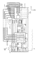
図1は本発明の一実施形態に係る液体消費装置の概略構成図である。本実施形態に係る液体消費装置としてのインクジェット式記録装置211は、図1に示すように、略矩形箱状をなす本体ケース212を備える。本体ケース212内の前方下部には、プラテン213が主走査方向となる本体ケース212の長手方向(図1において左右方向)に沿うように配設されている。プラテン213は、ターゲットとしての記録用紙Pを支持する支持台である。プラテン213上には、図示しない紙送り機構により記録用紙Pが主走査方向と直交する副走査方向に沿って給送されるようになっている。
FIG. 1 is a schematic configuration diagram of a liquid consuming apparatus according to an embodiment of the present invention. As shown in FIG. 1, an ink
本体ケース212内においてプラテン213の後部上方には、主走査方向に沿って棒状のガイド軸214が架設されている。このガイド軸214にはキャリッジ215がガイド軸214に沿って移動自在に支持されている。
また、本体ケース212内の後方側面においてガイド軸214の両端部と対応する位置には、駆動プーリ216及び従動プーリ217が回転自在に支持されている。駆動プーリ216にはキャリッジモータ218が連結されるとともに、一対のプーリ216,217間にはキャリッジ215を支持した無端状のタイミングベルト219が掛装されている。したがって、キャリッジ215は、キャリッジモータ218の駆動により、ガイド軸214に沿って主走査方向に往復移動可能となっている。
A rod-shaped guide shaft 214 is installed in the
A driving
本体ケース212内の一端側(図1では右端側)には、箱形状をなす容器ホルダとしてのカートリッジホルダ200が設けられている。カートリッジホルダ200は、その前壁及び上壁前部にあたる部分が開閉可能な蓋部221として構成されている。ユーザーは、この蓋部221を開放状態とすることで、液体収容容器としてのインクカートリッジ100を着脱交換することができる。すなわち、カートリッジホルダ200には、液体としてのインクの色毎に用意された複数個(本実施形態においては5個)のインクカートリッジ100が、蓋部221を開放状態としたもとで、前後方向への挿脱動作を伴って着脱されるようになっている。
A
各インクカートリッジ100は、カートリッジホルダ200に装着された場合、それぞれ対応する各インク供給路223の上流端に接続されるようになっている。また、各インク供給路223の下流端は、キャリッジ215上に搭載されたバルブユニット224の上流側とそれぞれ接続される。バルブユニット224の下流側は、キャリッジ215の下面側に設けられた液体噴射ヘッドとしての記録ヘッド225に接続されている。そして、インク供給路223及びバルブユニット224は、インクカートリッジ100から供給された液体を記録ヘッド225に供給する液体供給機構を構成している。
Each
カートリッジホルダ200とプラテン213との間には、記録ヘッド225の退避位置となるホームポジションHPが設けられている。そして、印刷の開始前などには、このホームポジションHPにおいて記録ヘッド225に対するクリーニング等、各種メンテナンス処理が実行される。
Between the
本体ケース212の内部において、カートリッジホルダ200の上方となる位置には、加圧ポンプ226が配置されている。加圧ポンプ226は、加圧空気(加圧流体)の供給源であり、加圧空気供給路227の上流端に接続されている。加圧空気供給路227は、加圧ポンプ226の下流側に配設された分配器228を境にインクカートリッジ100の個数と同数に分岐されている。分岐された加圧空気供給路227の下流端は、それぞれ対応するインクカートリッジ100に接続されている。そして、加圧ポンプ226、加圧空気供給路227、及び分配器228は、インクカートリッジ100に加圧流体を供給する加圧流体供給機構を構成している。なお、本実施形態では、加圧流体として空気を用いているが、空気と異なる気体や液体等を用いても良い。
A pressurizing
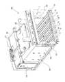
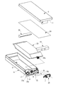
図2は液体収容容器を装着する容器ホルダの斜め上方からの斜視図、図3は図2に示した容器ホルダの斜め下方からの斜視図、図4は図2に示した容器ホルダの正面図、図5は図2に示した容器ホルダの分解斜視図である。
カートリッジホルダ200は、図2乃至図5に示すように、側面視略L字状をなすホルダ本体240と、断面コ字状をなす枠体260とで構成されている。
枠体260は、図5及び図7に示すように、一対の支持側壁262,262と、これら支持側壁262,262の上端縁を連結する天壁263とを備えている。枠体260は、金属板により一体にプレス成形されている。
2 is a perspective view of the container holder to which the liquid storage container is mounted from obliquely above, FIG. 3 is a perspective view of the container holder shown in FIG. 2 from obliquely below, and FIG. 4 is a front view of the container holder shown in FIG. FIG. 5 is an exploded perspective view of the container holder shown in FIG.
As shown in FIGS. 2 to 5, the
As shown in FIGS. 5 and 7, the
ホルダ本体240は、図5に示すように、樹脂材料または金属材料で平面視矩形状をなすように成形された基板241と、基板241の後方の上面に取り付けられた壁体244とを有している。
基板241は、インクカートリッジ100がカートリッジホルダ200に装着された場合に、各インクカートリッジ100を並列配置態様にして載置するための支持台である。基板241上には、第1の案内突起としての複数のガイドレール33が前後方向に沿って延びるように列設されている。ガイドレール33は、インクカートリッジ100をホルダ200に着脱する際に、インクカートリッジ100を案内するためのものである。カートリッジホルダ200の内部は、ガイドレール33によって、5つのカートリッジスロット7A、7B、7C、7D、7Eに区画される。カートリッジスロット7A〜7Eは、それぞれ各色のインクカートリッジ100を個別に収容する容器装着部として機能する。
As shown in FIG. 5, the holder
The
壁体244は、平面視コ字状をなす成形物である。壁体244は、前方側に開口を向けるようにして、基板241上に取り付けられている。壁体244の上端には、矩形状に成形された天板245が取り付けられている。壁体244の上面には、矩形状に成型された天板245が取り付けられている。
The
壁体244は、図示しない後方の面を有している。また、壁体244は、壁体244の後方の面と略平行に設けられた面246bを備えたスライダー部材246を有している。スライダー部材246は、図示しない付勢手段によって、前方、すなわちインクカートリッジ100の挿入方向とは反対の方向に付勢されている。スライダー部材246の面246bは、カートリッジスロット7A〜7Eの奥端面をなす。スライダー部材246は、インクカートリッジ100がカートリッジスロット7A〜7Eに装着されていない時は、付勢手段の力によって、前方側に位置している。
インクカートリッジ100をカートリッジスロット7A〜7Eに挿入すると、スライダー部材246は、インクカートリッジ100の先端面11(図9、図11、図12参照)に押されながら、後方に移動する。
インクカートリッジ100をカートリッジスロット7A〜7Eに完全に装着すると、スライダー部材246は、所定の位置で停止する。スライダー部材246は、インクカートリッジ100をカートリッジスロット7A〜7Eに装着されている時も、付勢手段の力によって、装着されたインクカートリッジ100に対して、その挿入方向とは反対の方向への付勢力を常時付与している。この付勢力は、インクカートリッジ100をカートリッジスロット7A〜7Eから取り外すときに、インクカートリッジを前方へ押し出すように作用する。
The
When the
When the
スライダー部材246には、壁体244の後方の面に設けられた一対の位置決めピン247,247、エア連絡口248、インク供給ピン249、識別部材251a〜251eを、壁体244の後方の面から前方へ露出させるための開口部246aが設けられている。
壁体244の後方の面、すなわちカートリッジスロット7A〜7Eそれぞれの奥端面には、一対の位置決めピン247,247、エア連絡口248、インク供給ピン249、識別部材251a〜251eが、スライダー部材246の開口部246aを介して前方へ突出するように設けられている。
The
A pair of positioning pins 247 and 247, an
一対の位置決めピン247,247、エア連絡口248、インク供給ピン249、識別部材251a〜251eは、いずれもまた、容器装着部1の奥端面であるスライダー部材246の前面において基板241上の各カートリッジスロット7A、7B、7C、7D、7Eに各インクカートリッジ100が装着された場合に機能するものである。
一対の位置決めピン247,247は、インクカートリッジ100を位置決めするためのものである。一対の位置決めピン247,247は、カートリッジスロット7A〜7Eそれぞれの奥端面の上下に一対ずつ設けられている。
エア連絡口248は、それら各インクカートリッジ100の位置決め穴21,23に挿入される上下一対の位置決めピン247,247インクカートリッジ100に空気を供給するためのものである。エア連絡口248は、カートリッジスロット7A〜7Eそれぞれの奥端面の下側に設けられている。また、エア連絡口248は、一対の位置決めピン247、247に挟まれた位置、かつ下側の位置決めピン247に近い位置に設けられている。
インク供給ピン249は、インクカートリッジ100からのインクを、インク供給路223(図1参照)を介して記録ヘッド225(図1参照)に供給するためのものである。インク供給ピン249は、カートリッジスロット7A〜7Eの奥端面の上側に設けられている。また、インク供給ピン249は、一対の位置決めピン247には挟まれない位置、かつ上下方向の位置が上側の位置決めピンに近い位置に設けられている。
The pair of positioning pins 247 and 247, the
The pair of positioning pins 247 and 247 are for positioning the
The
The
識別部材251a〜251eは、インクカートリッジ100の誤装着を防止するためのものである。識別部材251a〜251eは、カートリッジスロット7A〜7Eそれぞれの奥端面の下側に設けられている。また、識別部材251a〜251eは、一対の位置決めピン247、247に挟まれた位置、かつエア連絡口248のすぐ上側となる位置に設けられている。つまり、識別部材251a〜251eは、上側の位置決めピン247と、エア連絡口248に挟まれた位置、かつエア連絡口248に近い位置に設けられている。
The
そして、各エア連絡口248のすぐ上側となる位置からは、複数(本実施形態では5つ)の識別部材251a,251b,251c,251d,251eが遮蔽板246に下側から切欠き形成された切欠き部246aを介して先端部を前方へ突出するようにして設けられている。
これら識別部材251a〜251eは、基端となる後端面が開口して前後方向へ延びる中空柱状体である。各識別部材251a〜251eの先端には、凹凸嵌合部が形成されている。一方、インクカートリッジ100の挿入方向先端面には、各識別部材251a〜251eの凹凸嵌合部の形状に対応する識別部22(図9参照)が形成されている。識別部22の形状は、詳細な図示を省略しているが、インクカートリッジ100の種類によって異なっている。
A plurality (five in the present embodiment) of
These
また、各識別部材251a〜251eの凹凸嵌合部は、それぞれ一種類のインクカートリッジ100の識別部22とのみ嵌合することができ、他の種類のインクカートリッジ100の識別部22とは嵌合できない形状となっている。このように、本実施形態のインクジェット式記録装置は、インクカートリッジの識別部22と各識別部材251a〜251eの凹凸嵌合部との組み合わせによって、インクカートリッジ100の誤装着を防止できるように構成されている。
Further, the concave and convex fitting portions of the
図3及び図4に示したように、壁体244の天板245の対向面、すなわちカートリッジスロット7A〜7Eの上面の、手前側には、第2の案内突起としての断面三角形の案内突起265が、奥側には装置側端子250が設けられる。
As shown in FIGS. 3 and 4, a
案内突起265は、ガイドレール33に対向して配置されている。第2の案内突起250は、ガイドレール33と同様、インクカートリッジ100をホルダ200のカートリッジスロット7A〜7Eに着脱する際に、インクカートリッジ100を案内するためのものである。
The
また、装置側端子250は、インクカートリッジ100がカートリッジスロット7A〜7Eに装着された時に、インクカートリッジ100に設けられた回路基板17(図9参照)の電極の接点17a(図9参照)と接触して、この電極と電気的に導通接続する。
Further, the device-
カートリッジスロット7A〜7Eの下側かつ奥側(後方)には、装置側固定構造50が設けられている。図6(a)は、装置側固定構造50を構成するレバー部材45とバネ44とをカートリッジ100側から示す斜視図である。図6(b)は、装置側固定構造50をカートリッジ100とは反対の側から示す斜視図である。図6(c)は、装置側固定構造50周辺の断面図である。
A device-
図6(c)に示すように、装置側固定構造50は、基板241、すなわちカートリッジスロット7A〜7E(図3参照)の下面とほぼ平行に伸びるレバー部材45を備えている。
レバー部材45は、弾性を有する細長のレバー本体47と、レバー本体47の基端部に設けられた軸穴36と、レバー本体47の先端部の上側面(カートリッジ100側の面)に突設された略円柱状の係止ピン37(被係止部材)とを備えている。壁体244の底面243と基板241との間には隙間が設けられており、レバー部材45は、この隙間を利用して配置されている。
As shown in FIG. 6C, the apparatus-
The
壁体244の底面243には突部242が設けられている。レバー部材45の軸穴36は突部242に挿入される。レバー部材45は、突部242を中心に回動可能な状態で軸支される。つまり、突部242は、レバー部材45の回動軸としての役割を持つ。また、突部242の周囲は、キャップ38と、このキャップの溝に収容されたコイルバネ60によって支えられている。このバネ60は、レバー部材45を基板241に対して回動可能な状態で支持する機能と、レバー部材45を上方に付勢することによってレバー部材45の動きを安定させる機能とを備えている。
A
また、装置側固定構造50は、図6(a)及び(b)に示すように、レバー本体47に回転方向(−R方向)の付勢力を付与するバネ44を備えている。バネ44の一端は、レバー本体47の軸穴36の位置から係止ピン37へ向かう方向とは異なる方向へ偏倚した位置に設けられた係止部46に係止される。バネ44の他端は、壁体244の下面に設けられた係止部244bに係止される。レバー部材45にバネ44の付勢力に抗する力が付与されると、レバー部材45は図6(a)及び(b)中の矢印+R方向に回動する。
Further, as shown in FIGS. 6A and 6B, the device-
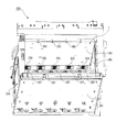
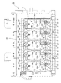
図7は液体収容容器を装着した容器ホルダの正面図、図8は一部の液体収容容器が脱着された容器ホルダの正面図である。そして、本実施形態によるインクカートリッジ100は、図7及び図8に示すように、液体消費装置である商業用のインクジェット式記録装置211(図1参照)のカートリッジホルダ200のカートリッジスロット7A〜7Eに着脱可能に装着されて、記録装置の記録ヘッド225にインクを供給する。
FIG. 7 is a front view of a container holder equipped with a liquid storage container, and FIG. 8 is a front view of the container holder with some liquid storage containers removed. As shown in FIGS. 7 and 8, the
図9は液体収容容器を一方の側面側から見た斜視図、図10は図9に示した液体収容容器の分解斜視図、図11は図8のA−A矢視図、図12は液体収容容器を他方の側面側から見た斜視図である。
このインクカートリッジ100は、図9に示したように、扁平な略直方体形状を有するケース5を備えている。ケース5の内部には、図10に示すように、袋体収容部3が区画形成されている。袋体収容部3には、液体収容室としてのインクパック20が設けられている。また、インクカートリッジ100は、液体残量検出ユニット30と、インク供給口7(液体供給口)を備えている。液体残量検出ユニット30は、ケース5に対して着脱可能である。また、インク供給口7は、液体残量検出ユニット30に設けられている。
9 is a perspective view of the liquid container as viewed from one side, FIG. 10 is an exploded perspective view of the liquid container shown in FIG. 9, FIG. 11 is a view taken along the line AA in FIG. 8, and FIG. It is the perspective view which looked at the storage container from the other side surface side.
As shown in FIG. 9, the
ケース5は、樹脂成形によって形成された筐体である。ケース5は、上部を開放した略箱形の袋体収容部3と、この袋体収容部3の前面側に位置する検出ユニット収容部4とを備えている。袋体収容部3には、インクパック20と樹脂製のスペーサ26が収容される。インクパック20は、樹脂フィルム層の上にアルミニウム層が積層形成されたアルミラミネート複層フィルムにより形成された可撓性袋体である。樹脂製のスペーサ26は、インクパック20の前後の傾斜部の上に装着される。また、検出ユニット収容部4には、液体残量検出ユニット30が収容される。
袋体収容部3の開放面は、インクパック20と樹脂製のスペーサ26を収容した後に、シートフィルム24によって封止される。袋体収容部3とシートフィルム24によって、ケース5内に加圧室が区画形成される。
The
The open surface of the
そして、スペーサ26は、袋体収容部3の上面がシートフィルム24によって覆われて、袋体収容部3が密封室となると、該密封室内でインクパック20がガタつくことを防止すると同時に、密封室内の余分な空き空間を埋めて、袋体収容部3内を加圧空気により加圧する際の加圧効率を高める。
袋体収容部3及び検出ユニット収容部4の開放面を封止したシートフィルム24の上には、樹脂製のカバー6が装着される。
Then, when the upper surface of the
A
本実施形態において、インクカートリッジ100は、5種類ある。5種類のインクカートリッジ100の、インクパック20内には、それぞれ異なる5色のインクが貯留されている。これら5種類のインクカートリッジ100は、インクパック20の内部に貯留されているインクの種類と、先に説明したように識別部22の詳細な形状が異なるだけで、他の構成は一致している。
In the present embodiment, there are five types of
図9及び図11に示すように、インクカートリッジ100は、略長方形の先端面11と、これと対向する後端面12とを有している。先端面11、後端面12は、インクカートリッジ100をカートリッジスロット7A〜7Eに装着する際に、それぞれ挿入方向の先端、後端となる面である。また、図7〜図9、図11、及び図12に示すように、インクカートリッジ100は、略長方形の先端面11の第1の短辺13aにおいて先端面11と交わる第1の側面15、略長方形の先端面11の第2の短辺13bにおいて先端面11と交わる第2の側面25、略長方形の先端面11の第1の長辺14aにおいて先端面11と交わる第3の側面35a、略長方形の先端面11の第2の長辺14bにおいて先端面11と交わる第4の側面35bを有している。
As shown in FIGS. 9 and 11, the
図7、図8、及び図11に示すように、インクカートリッジ100は、縦置きでカートリッジスロット7A〜7Eに装着される。
インクカートリッジ100は、第1の側面15が上側、第2の側面25が下側となるように、カートリッジスロット7A〜7Eに装着される。また、インクカートリッジ100は、第3の側面35a及び第4の側面35bを、鉛直面と平行となる向きに対向させて、平行に、複数並べて基板241上に載置される。図7に示すように、カートリッジホルダ200の一対の支持側壁262のうち一方は、両外端のインクカートリッジ100のうち、一方の第3の側面35aと対向する。また、他方の支持側壁262は、両外端のインクカートリッジ100のうち、他方の第4の側面35aと対向する。
As shown in FIGS. 7, 8, and 11, the
The
図9および図15に示すように、先端面11には、インク供給口7と、エア流入口9とが設けられている。インク供給口7はインクパック20(図10参照)のインク吐出口20aと接続されている。インク吐出口20aは、インクパック20の先端面の中央付近に位置している。つまり、インクカートリッジ100がカートリッジスロット7A〜7Eに装着された状態において、インク供給口7はインクパックの高さ方向(上下方向)の中央よりも上側にずれて配置されている。そして、インク供給口7とインク吐出口20aとの間には、これらを繋ぐ流路19が設けられている。
インクカートリッジ100がカートリッジスロット7A〜7Eに装着されていない時、インク供給口7は弁やシールによって閉塞されている。このとき、インク供給口7には、インクパック20に充填されたインクがインク供給口7から外に出ようとする圧力(静圧)が働く。この静圧は、インクパック20内のインクの量が多いほど高いので、インクが十分充填された初期状態の静圧(初期静圧)が高いことになる。そして、このインクパック内の静圧が比較的高い状態でインク供給口7を開放すると、インク供給口7からインクが漏れ出してしまう可能性がある。
しかし、本実施形態のように、インク供給口7がインクパック20の高さ方向(上下方向)の中央よりも上側に位置するようにすれば、インク供給口7に位置におけるインクパック20内のインクの静圧は低くなり、さらにインク供給口7とインク吐出口20aを接続する流路19によってもたらされる流路抵抗などの作用により、インク供給口7に働く静圧を低減することが可能である。つまり、本実施形態によれば、インクカートリッジ100をカートリッジスロット7A〜7Eに装着した場合でも、インク供給口7へインク供給ピン249が挿入される際に、インク供給口7からインクが漏れにくい。
As shown in FIGS. 9 and 15, the
When the
However, if the
ここで、図1、図4、図5、図9〜図12に基づいて、インクパック20から記録ヘッド225へのインクの供給について説明する。
インクカートリッジ100をカートリッジスロット7A〜Eに装着すると、インク供給口7に、先に説明したインク供給ピン249が挿入される。インク供給ピン249は、インク供給路223とバルブユニット224とを介して記録ヘッド225に接続されている。
Here, the ink supply from the
When the
また、インクカートリッジ100をカートリッジスロット7A〜Eに装着すると、エア流入口9が、先に説明したエア連絡口248に挿入される。エア連絡口248は、加圧空気供給路227を介して加圧ポンプ226に接続されている。加圧ポンプ226が、加圧空気供給路227、エア連絡口248、エア流入口9を介して、袋体収容部3に加圧空気を供給することで、インクパック20を加圧することができる。インクパック20がこのようにして加圧されるにより、インクパック20の吐出口20aから流出するインクが、インク供給口7を介してインクジェット式記録装置211の記録ヘッド225へと供給される。
Further, when the
図9及び図12に示すように、インクカートリッジ100の先端面11には、互いに離間して一対の位置決め穴21,23が設けられている。図4、図5、図9、図11に基づいて、位置決め穴21,23と先に説明した一対の位置決めピン247,247の機能を説明する。
As shown in FIGS. 9 and 12, the
インクカートリッジ100をカートリッジスロット7A〜7Eに挿入すると、位置決めピン247,247の先端が、位置決め穴21,23に嵌入される。その後、更にインクカートリッジ100をカートリッジスロット7A〜7Eの奥側へ挿入していくと、インクカートリッジ100は、位置決めピン247を基準に移動する。
When the
インクカートリッジ100がカートリッジスロット7A〜7Eに完全に装着されると、位置決め穴21,23が、一対の位置決めピン247,247と嵌合することにより、インクカートリッジ100の先端面11に沿う方向の位置が決められて、先端面11に沿う方向のカートリッジ100の移動が規制される。
なお、図11に示すように、一対の位置決め穴21,23と、後述する回路基板17及び容器側固定構造40は、略同一縦断面A−A(図8参照)上に配置されている。
When the
As shown in FIG. 11, the pair of positioning holes 21 and 23, the
図9及び図12からわかるように、本実施の形態において、一方の位置決め穴21は、位置決めピン247の軸方向と垂直な断面形状にほぼ対応する形状である丸孔に設定され、他方の位置決め穴23はケース5の高さ方向(図9と図12の矢印H方向、すなわち上下方向)に細長い長穴に設定されている。このように、一方の位置決め穴23を長穴に形成しておくことで、位置決め精度を保つ一方で寸法公差等の許容が容易になる。
As can be seen from FIGS. 9 and 12, in the present embodiment, one
つまり、カートリッジ100をカートリッジスロット7A〜7Eに装着した時、カートリッジスロット7A〜7E内におけるカートリッジ100の位置決めの精度は、上側の位置決め穴21で保たれ、寸法公差等による位置決め穴23と位置決めピン247(図4参照)との相対的な位置ずれについては、下側の位置決め穴23によって吸収される。そして、インク導出口7は、位置決め精度を保つ上側の位置決め穴21の近傍に設けられている。よって、インク導出口7とインク供給ピン249(図4参照)とが精度良く位置決めされる。
That is, when the
図9に示すように、インクカートリッジ100の第1の側面15には、回路基板17が設けられている。回路基板17は、後端面12よりも先端面11に近い位置、特に、先端面11と隣接するような位置に設けられている。回路基板17には、インク残量やカートリッジの使用履歴等の情報を記録するための図示しないメモリ素子が搭載される。
As shown in FIG. 9, a
また、液体残量検出ユニット30には、図示しない残量検出センサ(圧電素子を用いたセンサ)が設けられている。残量検出センサは、インクカートリッジ内のインクの残量を検出するためのセンサである。回路基板17上には、この残量検出センサと電気的に同通接続する少なくとも1つの電極が設けられている。
The liquid remaining
一方、図11に示すように、回路基板17の上側には、装置側端子250が設けられている。そして、回路基板17の電極の接点17aは、先に説明したように、インクカートリッジ100がカートリッジスロット7A〜7E(図3、図7、図8参照)に装着された時に、装置側端子250(図3、図7、図8参照)の接点250aと接触する。これによって、当該電極と装置側端子250とが、電気的に導通する。
なお、回路基板17が先端面11の近傍に設けられ、位置決め精度を保つ上側の位置決め穴23が第1の側面15の近傍に設けられていることで、回路基板17の電極の接点17aと装置側端子250の接点250aとが精度良く位置決めされる。
On the other hand, as shown in FIG. 11, device-
The
インクカートリッジ100が記録装置211(図1参照)のカートリッジホルダ200に装着されて、回路基板17の電極の接点17aが容器装着部1の装置側端子250の接点250aに接触すると、この回路基板17を介して、メモリ素子や残量検出センサが記録装置211(図1参照)側の制御回路に電気的に接続され、これらのメモリ素子や残量検出センサの動作を記録装置211(図1参照)側から制御することが可能となっている。
When the
図7〜図9及び図12に示すように、インクカートリッジ100の第1の側面15と第4の側面35bとが互いに交わる辺に対応する角部27aと、第2の側面25と第4の側面35bとが互いに交わる辺に対応する角部27bは、それぞれインクカートリッジ100の挿入方向(図9の矢印X方向)に沿って切り欠かれた形状となっている。すなわち、角部27a,27bには、一対のC面29a,29bが設けられている。また、図2〜図5、図7、図8に示すように、カートリッジホルダ200の内部にカートリッジ100間を仕切る壁は設けられていない。
As shown in FIGS. 7 to 9 and 12, the
したがって、図7に示すように、扁平な略直方体形状のインクカートリッジ100が縦置き、すなわち第1の側面15を上に、第2の側面を下にした状態で平行に並べられて収容されると、インクカートリッジ100は、第3の側面35aと第4の側面35bとが、隣接する複数のインクカートリッジ100間で互いに対向するように、並列に配置される。そして、隣接するインクカートリッジ100同士の間において一方のインクカートリッジ100のC面29a,29bによって、断面三角形の空間31a,31bが、インクカートリッジ100の挿入方向に延在して形成される。
Accordingly, as shown in FIG. 7, flat, substantially rectangular
一方、カートリッジホルダ200には、図2、図5、図6、及び図7に示したように、C面29が形成された角部27の切欠き形状(空間31)に対応した断面三角形の案内突起であるガイドレール33が、インクカートリッジ100の挿入方向に沿って設けられている。
また、図5に示したように、上側のC面29aによって形成された上側の空間31aに対応した断面三角形の案内突起265が、カートリッジスロット7A〜7Eの上面の手前側に設けられている。従って、断面三角形の空間31a,31bのうち、下側の空間31bがガイドレール33の設置空間となり、上側の空間31aは案内突起265の設置空間となる。
On the other hand, the
Further, as shown in FIG. 5, a
また、図3に及び図4に示すように、カートリッジスロット7A〜7Eの少なくとも着脱用開口の付近には、上側のC面29aによって形成された上側の空間31aに対応した断面三角形の案内突起265が突設されている。案内突起265は、支持台241に設けたガイドレール33に対向して、天井部に配置されている。従って、断面三角形の空間31a,31bのうち、下側の空間31bがガイドレール33の設置空間となり、上側の空間31aは案内突起265の設置空間となる。
As shown in FIGS. 3 and 4, at least in the vicinity of the opening for attaching / detaching the
そして、C面29bに対応した断面三角形のガイドレール33が、インクカートリッジ100の挿入方向に沿って設けられた構造では、扁平な略直方体形状のインクカートリッジ100を縦置きで平行に複数個並べてカートリッジホルダ200に収容する場合、隣接するインクカートリッジ100同士の間の下部に形成された断面三角形の空間31bに、略同一の断面三角形のガイドレール33を、インクカートリッジ100の挿入方向に配置できる。
各インクカートリッジ100は、ガイドレール33により、カートリッジホルダ200内で挿入方向へ案内及び位置決めされる。よって、隣接するインクカートリッジ100同士の間には、カートリッジホルダ200の各カートリッジスロット(スロット)7A、7B、7C、7D、7Eを仕切る隔壁が必要なくなる。
In the structure in which the guide rails 33 having a triangular cross section corresponding to the
Each
そして、インクをインクジェット式記録装置211に供給する為、袋体収容部3に加圧空気を導入してインクパック20を外部から加圧すると、図8に想像線で図示したように各インクカートリッジ100のケース5は主に平行な一対の最大面(第3及び第4の側面)35a,35bが膨張変形する。膨張変形の量は、カートリッジ100の大きさやケース5の材質、袋対収容部3に導入される加圧空気の圧力等、様々な条件によって変化するが、例えば加圧空気の圧力が12〜18kPaの場合、最大片側5〜10mm程度になることがある。
Then, in order to supply ink to the ink
本実施形態では、カートリッジホルダ200内に隔壁が存在しないため、袋体収容部3に加圧空気を導入すると、隣接するケース5の最大面35a,35b同士が膨張変形する。そして、隔壁がないカートリッジスロット7A〜7E内で、隣接するインクカートリッジ100の最大面35a,35b同士の少なくとも一部が接触して圧接し合う。また、両外側端のインクカートリッジ100の最大面35a,35bのうち、他の容器の最大面35b,35aと対向しない最大面35a,35bの少なくとも一部は、図7に示すように、それぞれ対向する枠体260の支持側壁262と接触して圧接し合う。
In this embodiment, since there is no partition in the
即ち、図7に示したように、カートリッジスロット7A〜7Eに装着された各インクカートリッジ100に加圧流体を導入すると、カートリッジ100は、それら自体の膨張力により一対の支持側壁262,262間で緊締状態となる。そして、膨張変形を規制された複数のインクカートリッジ100が強固かつ一体的にカートリッジスロット7A〜7Eに固定される。
一方、加圧室の加圧が解除され、膨張していたインクカートリッジ100が元の形状に戻ると、隣接するインクカートリッジ100同士や、カートリッジ100と支持側壁262との間の圧接が無くなるので、各インクカートリッジ100の着脱はスムーズに行うことができる。
That is, as shown in FIG. 7, when the pressurized fluid is introduced into each of the
On the other hand, when the pressurization of the pressurizing chamber is released and the expanded
図13は図12のB部拡大図、図14は図13に示した案内溝の拡大平面図である。
図12及び図13に示すように、第2の側面25には、挿入方向と反対の方向への付勢力に抗してインクカートリッジ100がカートリッジスロット7A〜7Eに装着された状態において、カートリッジスロット7A〜7Eに設けられた装置側固定構造50と協働して、インクカートリッジ100の挿入方向と反対方向への移動を解除可能に規制する容器側固定構造40が設けられている。装置側固定構造40は、後端面12よりも先端面11に近い位置、特に、先端面11と隣接するような位置に設けられている。また、第2の側面25の、容器側固定構造40よりも先端面11から遠い位置には、凹部43が配設されている。凹部43は、先端面と隣接してはいないものの、後端面12よりも先端面11に近い位置に設けられている。
13 is an enlarged view of a portion B in FIG. 12, and FIG. 14 is an enlarged plan view of the guide groove shown in FIG.
As shown in FIGS. 12 and 13, the
容器側固定構造40は、図13に示すように、装置側固定構造50(図3参照)の係止ピン37が挿入され、カートリッジスロット7A〜7Eへのインクカートリッジ100の着脱操作に際して被係止部材としての係止ピン37を係止位置又は非係止位置へ案内する案内溝39を有する。また、容器側固定構造40は、インクカートリッジ100がカートリッジスロット7A〜7Eに装着された状態において、係止ピン37が係合されてインクカートリッジ100の引抜き方向への移動を規制する係止部49を有する。
As shown in FIG. 13, the container
図13に示すように、案内溝39は、インクカートリッジ100がカートリッジスロット7A〜7Eに挿入される際に、係止ピン37を案内する入口側案内部51と、カートリッジスロット7A〜7Eに挿入されたインクカートリッジ100が引抜き方向へ押し返される際に係止ピン37を係止部49に導く中間案内部53と、カートリッジスロット7A〜7Eからインクカートリッジ100を取り外す際に、インクカートリッジ100を挿入方向へ押し込むことにより係止部49から外れた係止ピン37を、案内溝39の出口に案内する出口側案内部55と、を備えている。
As shown in FIG. 13, the
案内溝39の出口部57は入口部59に接続されており、これにより案内溝39は全体としてループを成している。入口部59と出口部57との接続部においては、出口部57の溝の深さが入口部59の溝の深さよりも浅く、これにより接続部において段差65が形成されている。この段差65は、インクカートリッジ100がカートリッジスロット7A〜7Eに挿入される際に、係止ピン37が出口部57に進入するのを防止する。
The
一方、図9に示すように、容器側固定構造40の下側には、装置側固定構造50が設けられている。装置側固定構造50は、先に説明したように、図6(b)に示すレバー部材45とバネ44とを備えている。
On the other hand, as shown in FIG. 9, an apparatus
レバー部材45は、バネ44によって一定の回転方向に付勢されている。この方向は、図6(b)では矢印−R方向であり、図13では反時計回り方向である。インクカートリッジ100をカートリッジスロット7A〜7Eに着脱する際、係止ピン37は案内溝39に挿入されて案内され、レバー部材45は案内溝39の形状に従って±R方向へ回動する。
The
レバー部材45の先端部に設けられた係止ピン37は、図11に示すように、インクカートリッジ100の第2の側面25と交わる方向に設けられている。係止ピン37が案内溝39に挿入されている時、係止ピン37は、レバー部材45を構成するレバー本体47の弾性力によって、案内溝39の底面を上側に押圧する
The locking
次に、図14を主に参照して、インクカートリッジ100の着脱操作時における案内溝39内での係止ピン37の動作について説明する。
カートリッジスロット7A〜7Eにインクカートリッジ100を挿入し、スライダー部材244(図4及び図5参照)の付勢力に抗してインクカートリッジ100を挿入方向にさらに押し込むと、係止ピン37が案内溝39の入口部59に挿入される。
Next, the operation of the locking
When the
係止ピン37は、レバー部材45(図6参照)のレバー本体47(図6参照)が弾性的に変形することで、案内溝39の底面の方向に向けて付勢される。係止ピン37が、入口側案内部51の終端部を越えると、バネ44(図6参照)の付勢力によって図14の反時計方向に移動する。
そして、係止ピン37は暫定停止用側壁部61に衝突して止まり、このときにクリック音が生じる。このクリック音によりユーザーは、インクカートリッジ100が十分に深く挿入されたことを確認することができる。
The locking
Then, the locking
次に、ユーザーによる挿入方向への押圧が解除されると、スライダー部材246(図4及び図5参照)の付勢力によって、インクカートリッジ100が引抜き方向に僅かに押し返される。これにより、暫定停止用側壁部61における係止ピン37の係合が解除され、係止ピン37は、バネ44の付勢力によって、反時計回り方向に移動する。
そして、係止ピン37は係止部49に設けられた最終停止用側壁部63に衝突して係止位置で止まり、このときにクリック音が生じる。このクリック音によりユーザーは、インクカートリッジ100がカートリッジスロット7A〜7E(図2、図4、図5、図7及び図8参照)に固定されたことを確認することができる。なお、インクカートリッジ100がカートリッジスロット7A〜7Eに装着された状態においても、係止ピン37は、レバー本体47の弾性力によって案内溝39の底面を押圧している。
Next, when the pressing in the insertion direction by the user is released, the
Then, the locking
そして、カートリッジ脱着時には、係止状態のインクカートリッジ100が押し込まれることにより、最終停止用側壁部63における係止ピン37の係合が解除され、バネ44によってレバー部材45に付与される付勢力によって、係止ピン37が出口側案内部55に沿って非係止位置へと相対移動する。すると、カートリッジ100は、スライダー部材246(図3参照)の付勢力によって、前方へ押し出される。この時のカートリッジ100の動きに伴って、係止ピン37は出口部57へと向かう。そして、最終的に出口部57から係止ピン37が抜けることで、カートリッジスロット7A〜7Eからインクカートリッジ100を取り外すことができるようになる。
なお、図12及び図13に示すように、インクカートリッジ100の第2の側面25に凹部43が配設されているが、この凹部43に特段の機能は持たせていない。
Then, when the cartridge is detached, the locked
As shown in FIGS. 12 and 13, the
次に、図11を主に参照して、インクカートリッジ100を装着した状態、つまり、係止ピン37が係止部49に係止された状態における、装置側端子250と係止ピン37の位置の関係について説明する。
装置側端子250は、インクカートリッジ100の第1の側面15に設けられた回路基板17の電極の接点17aと接触する接点250aを有する。接点250aは、係止部49に係止された係止ピン37の位置よりも、インクカートリッジ100の先端面11に寸法Sだけ近い位置で、接点17aに接触している。
Next, referring mainly to FIG. 11, the positions of the apparatus-
The device-
以上述べたように、本実施形態によれば、図7に示したように、インクカートリッジ100がカートリッジスロット7A〜7Eに装着された際に、隣接するカートリッジ100同士の間に、C面29によって空間31bが形成される。そして、空間31bに、案内突起33が配置される。
各カートリッジ100は、案内突起33により、挿入方向に案内され及びカートリッジスロット7A〜7E内において位置決めされる。つまり、隣接するカートリッジ100同士の間には、カートリッジスロット7A〜7Eを仕切る隔壁が存在しない。
従って、複数のインクカートリッジ100を、隔壁や案内突起33の分、離間して配置する必要がない。つまり、複数のインクカートリッジ100を近接させて(高密度に)収納することが可能となる。よって、容器の厚み方向の収容総幅寸法が小さいコンパクトなカートリッジホルダ200を形成することができる。また、インクジェット式記録装置211全体をコンパクトにできる。
As described above, according to the present embodiment, as shown in FIG. 7, when the
Each
Therefore, it is not necessary to dispose the plurality of
また、本発明によれば、先に説明したように、インクカートリッジ100を加圧した際に、各容器の膨張変形が規制されるので、装置側端子250と回路基板17の接点17aとのずれを防ぐことができ、これらの電気的接続性の低下を防止できる。また、後述する装置側固定構造50と容器側固定構造40の係合部に加わる負荷も低減できる。また、複数のインクカートリッジ100がそれら自体の膨張力により強固に一体的にカートリッジスロット7A〜7Eに固定されるので、ホルダ200にカートリッジスロット7A〜7E同士を仕切る隔壁を設ける必要がなくなり、ホルダ200を簡素化かつ小型化することが可能となる。
Further, according to the present invention, as described above, when the
また、回路基板17の電極の接点17aと容器側固定構造40とが、インクカートリッジ100の第1の側面15と第2の側面25にそれぞれ配置されることで、隣接するカートリッジ100の第3の側面35aまたは第4の側面35b同士の間に、装置側端子250や装置側固定構造50を配設する必要がなくなるため、複数のインクカートリッジ100を高密度に収容することが可能となる。
すなわち、本実施形態によれば、装置側端子250と回路基板17の接点17aとの電気的接続性を低下させることなく、複数のインクカートリッジ100を高密度に収容することが可能となる。
Further, the
That is, according to the present embodiment, a plurality of
また、図2及び図5に示すように、本実施形態において、ガイドレール33は、インクカートリッジ100の第3の側面35aまたは第4の側面35bを鉛直面と平行となる向きに対向させて、平行に、複数個並べて載置する基板241上に設けられている。
よって、インクカートリッジ100をカートリッジスロット7A〜7Eに装着した際に、隣接するインクカートリッジ100の間の下部に、案内突起33が配置される。
つまり、インクカートリッジ100をカートリッジスロット7A〜7Eに対して着脱する際に、各カートリッジ100の下部が案内される。よって、カートリッジ100の着脱操作が容易となる。また、カートリッジスロット7A〜7E内において、カートリッジ100がより確実に位置決めされる。
As shown in FIGS. 2 and 5, in this embodiment, the
Therefore, when the
That is, when the
また、図3、図4、及び図7に示すように、本実施形態では、ガイドレール33に対向して案内突起265が設けられている。よって、インクカートリッジ100を着脱する際、インクカートリッジ100の下面側がガイドレール33によって案内されるだけでなく、上面側も案内突起265によって案内されるので、インクカートリッジ100の脱着が更に容易となる。
なお、ガイドレール33や案内突起265(図4参照)の断面形状は、インクカートリッジ100を挿入案内可能であれば三角形に限らず、種々の断面形状を採りうることは勿論である。また、ガイドレール33や案内突起265の断面形状に応じて、C面の形状を適宜変更することも可能である。
さらに、案内突起265(図4参照)は省略しても良く、この場合は案内突起265に対応するC面29aを省略しても良い。さらにまた、案内突起265(図4参照)やガイドレール33の形状や位置に応じて、C面29aあるいはC面29bを、第3の側面35aと第1の側面15とが互いに交わる辺に対応する角部27c(図9及び図12参照)や、第3の側面35aと第2の側面25とが互いに交わる辺に対応する角部27d(図9及び図12参照)に設けたりすることも可能である。つまり、C面は、第1乃至第4の側面15,25,35a,35bのうち2つが互いに交わる辺に対応する4つの角部27a〜27dのうち、少なくとも1つに設けられていれば良い。
In addition, as shown in FIGS. 3, 4, and 7, in this embodiment, a
It should be noted that the cross-sectional shapes of the
Furthermore, the guide protrusion 265 (see FIG. 4) may be omitted. In this case, the
また、図10に示すように、本実施形態において、インクカートリッジ100の加圧室は、一面を開放面とした箱型の袋体収容部3と、当該開放面を封止するシートフィルム24によって区画形成される。従って、袋体収容部3及びインクパック20の密閉構造が容易に構成することができ、製造コストの低減が可能となる。
Further, as shown in FIG. 10, in the present embodiment, the pressurizing chamber of the
本実施形態では、図9、図11、及び図12に示すように、インクカートリッジ100に一対の位置決め穴21,23が設けられている。また、図4及び図5に示すように、カートリッジスロット7A〜7Eには、一対の位置決め穴21,23と嵌合する一対の位置決めピン247,247が設けられている。これらによって、インクカートリッジ100を正確な傾きでカートリッジスロット7A〜7Eに装着することができるため、インクカートリッジ100をカートリッジスロット7A〜7Eに装着する操作が容易となる。また、インクカートリッジ100が誤った傾きで着脱されることで、回路基板17、装置側端子250、容器側固定構造40、装置側固定構造50等を壊してしまうのを防ぐことができる。また、インクカートリッジ100がカートリッジスロット7A〜7Eに装着されている時に、回路基板17と装置側端子250との間の導通や、容器側固定構造40と装置側固定構造50との間の固定状態を良好な状態で維持することが可能となる。
In the present embodiment, as shown in FIGS. 9, 11, and 12, the
また、本実施形態では、図11に示すように、一対の位置決め穴21,23と、回路基板17と、容器側固定構造40とが、略同一の縦断面A−A(図8参照)上に配置されている。このように構成することで、インクカートリッジ100がカートリッジスロット7A〜7Eに挿入され、一対の位置決めピン247,247が一対の位置決め穴21,23に嵌入されると、カートリッジ100が先端面11に沿う方向(すなわち、縦断面と平行な方向)で位置決めされ、この縦断面上の一方に位置する回路基板17の接点17aと装置側端子250の接点250a、及び他方に位置する容器側固定構造40と装置側固定構造50同士のそれぞれが、接近・離反方向で高精度に位置決めされる。
Moreover, in this embodiment, as shown in FIG. 11, a pair of positioning holes 21 and 23, the
なお、本実施形態では、図7に示したように、扁平な略直方体形状のインクカートリッジ100が縦置きで平行に並べられているが、このインクカートリッジを上下方向に積み重ねるように並べても良い。つまり、インクカートリッジ100の第3の側面35aまたは第4の側面35bを鉛直面と垂直となる向きに対向させて配置しても良い。
しかしながら、本実施形態のように縦置きで平行に並べた方が、特に、回路基板17が設けられた第1の側面15及び装置側端子250が上側、容器側固定構造40が設けられた第2の側面25及び装置側固定構造50が下側となるように配置した方が、インク供給口7とインク供給ピン249の間からインクが漏れてしまった場合に、漏れ出したインクによって回路基板17が電気的に不良となってしまうのを防ぐことができる点で、有利である。
In this embodiment, as shown in FIG. 7, the flat, substantially rectangular
However, in the present embodiment, the
また、本実施形態では、回路基板17、位置決め穴21、インク供給口7が、すべて上側に集積されている。先に説明したとおり、これらが近接して配置されることにより、回路基板17と装置側端子250の位置精度、インク供給口17とインク供給ピン249の位置精度を高めることができる。そして、インク供給口7が上側に設けられることで、インクパック20の吐出口20aをこれよりも下側に配置することが可能となり、初期静圧を低減することが可能となる。すなわち、本実施形態のように、第1の側面15が上側、第2の側面25が下側となるように配置すれば、回路基板17と装置側端子250の位置精度、インク供給口17とインク供給ピン249の位置精度を向上させつつ、初期静圧をも低減できるような構成を実現しやすい。
In the present embodiment, the
また、本実施形態では、図11に示すように、回路基板17と容器側固定構造40は、後端面12よりも先端面11に近い位置に配置されている。そして、インクカートリッジ100がカートリッジスロット7A〜7Eに挿入されると、装置側固定構造50の付勢手段は、係止ピン37が容器側固定構造40の案内溝39の底面を上側に押圧するように係止ピン37を付勢する。つまり、インクカートリッジ100の下面となる第2の側面25が、係止ピン37によって、上面となる第1の側面15に向かって押圧される。従って、インクカートリッジ100の第1の側面15に設けられた回路基板17の接点17aが、インクジェット式記録装置211の装置側端子250へと押し付けられる(接点17a,25a同士を接近させる)構成となり、回路基板17の電極と装置側端子250とが確実に接続される。
In the present embodiment, as shown in FIG. 11, the
特に、本実施形態では、図11に示すように、インクカートリッジ100を装着した状態、つまり、係止ピン37が係止部49に係止された状態において、接点250aは、係止部49に係止された係止ピン37の位置よりも、インクカートリッジ100の先端面11に寸法Sだけ近い位置で、接点17aに接触している。この状態で、容器側固定構造40の案内溝39の底面を装置側固定構造50の係止ピン37が上方へ押圧するので、インクカートリッジ100の先端面11側が、後端面12側の支持部70を中心に上方に向かって回動される。
In particular, in the present embodiment, as shown in FIG. 11, the
そして、第1の側面15に設けられた回路基板17の電極の接点17aは、装置側端子250へと押し付けられるが、接点17aは、係止ピン37による容器側固定構造40の案内溝39の底面の移動量よりも大きく装置側端子250側へ移動する。これにより、接点17aがより強く装置側端子250へと押し付けられる構成となり、回路基板17の電極と装置側端子250がより確実に接続される。
The
5…ケース、7…インク供給口(液体供給口)、11…先端面、15…第1の側面、17…回路基板、17a…接点、21,23…位置決め穴、25…第2の側面、27a,27b…角部、29a,29b…C面、33…ガイドレール(第1の案内突起)、35a,35b…第3,第4の側面(最大面)、37…係止ピン、39…案内溝、40…容器側固定構造、50…装置側固定構造、52…装置側飛び出し防止構造、100…インクカートリッジ(液体収容容器)、200…カートリッジホルダ(容器ホルダ)、211…インクジェット式記録装置(液体消費装置)、225…記録ヘッド(液体噴射ヘッド)、250…装置側端子、260…枠体、262…支持側壁、263…天壁、X…挿入方向。
DESCRIPTION OF
Claims (11)
前記液体収容容器の前記第1の側面と前記第2の側面の何れかを支持する支持台と、
前記支持台上において前記液体収容容器の着脱方向に沿って延設され、各々が前記切欠き部に対応する形状を有する複数のガイドレールと、
前記液体収容容器の着脱時に通過する開口を備え、前記複数のガイドレールによって仕切られた複数の容器装着部と、
前記回路基板上の電極と接触して前記電極と電気的に導通する装置側端子と、
前記容器側固定構造と協働して、前記液体収容容器が装着される方向と反対方向への移動を解除可能に規制する装置側固定構造と、
前記容器装着部に装着された複数の前記液体収容容器のうち両外端の液体収容容器の前記最大面のうち、他の液体収容容器の前記最大面と対向しない最大面とそれぞれ対向する一対の支持側壁と、
を備えることを特徴とする容器ホルダ。 First short side, a second short side, a first long side, and a substantially rectangular front end surface having a second long side, the first side surface intersecting the front end face in the previous SL first short side When the tip before SL and a second side intersecting the distal surface at the second short side, a third side before Symbol first long side intersects with the distal end surface, previous SL second long side A fourth side surface intersecting the surface, a rear end surface facing the front end surface, a circuit board provided on the first side surface, a container side fixing structure provided on the second side surface, and the first Thru | or the 4th side, the notch part formed along the corner | angular part corresponding to the edge | side where two mutually cross | intersect, the liquid storage chamber in which the liquid was accommodated, and said liquid by introducing pressurized fluid A pressurizing chamber for pressurizing the storage chamber, and a liquid supply port for supplying the liquid to the liquid ejecting head, Liquid container configured substantially flat rectangular parallelepiped wherein the third aspect fourth sides as the maximum surface, are detachably mounted respectively in a state arranged in parallel with a plurality is opposed to the largest surface of one another A container holder for a liquid consuming device,
A support for supporting either the first side surface or the second side surface of the liquid container;
A plurality of guide rails extending along the attachment / detachment direction of the liquid container on the support base, each having a shape corresponding to the notch,
A plurality of container mounting portions provided with openings through which the liquid container is attached and detached, and partitioned by the plurality of guide rails ;
A device-side terminals that conduct to the electrode and the electrical contact with the electrodes before Kikai path substrate,
In cooperation with the front Kiyo-side fixing structure, a device-side fixing structure said liquid container is releasably restricting the movement in the direction opposite to the direction to be attached,
Of the plurality of liquid storage containers mounted on the container mounting portion, a pair of surfaces facing each of the maximum surfaces of the liquid storage containers at both outer ends that do not face the maximum surfaces of the other liquid storage containers. A supporting side wall;
A container holder comprising:
第1の短辺、第2の短辺、第1の長辺、および第2の長辺を有する略長方形の先端面と、前記第1の短辺において前記先端面と交わる第1の側面と、前記第2の短辺において前記先端面と交わる第2の側面と、前記第1の長辺において前記先端面と交わる第3の側面と、前記第2の長辺において前記先端面と交わる第4の側面と、前記先端面と対向する後端面と、前記第1の側面に設けられた回路基板と、前記第2の側面に設けられた容器側固定構造と、前記第1乃至第4の側面のうち少なくとも2つが互いに交わる辺に対応する角部に沿って形成された切欠き部と、液体が収容された液体収容室と、加圧流体が導入されることで前記液体収容室を加圧するための加圧室と、前記液体を前記液体噴射ヘッドに供給する液体供給口と、を備え、前記第3の側面と前記第4の側面が最大面として構成された扁平な略直方体形状の複数の液体収容容器と、
前記液体収容容器に前記加圧流体を導入する加圧流体供給機構と、
前記液体収容容器から供給された前記液体を前記液体噴射ヘッドに供給する液体供給機構と、
前記液体収容容器が互いの前記最大面を対向させて平行に複数個並べた状態でそれぞれ着脱可能に装着される請求項1乃至3の何れか1項に記載の容器ホルダと、
を備えることを特徴とする液体消費装置。 A liquid ejecting head for ejecting liquid;
First short side, a second short side, a first long side, and a substantially rectangular front end surface having a second long side, the first side surface intersecting the front end face in the previous SL first short side When the tip before SL and a second side intersecting the distal surface at the second short side, a third side before Symbol first long side intersects with the distal end surface, previous SL second long side A fourth side surface intersecting the surface, a rear end surface facing the front end surface, a circuit board provided on the first side surface, a container side fixing structure provided on the second side surface, and the first Thru | or the 4th side, the notch part formed along the corner | angular part corresponding to the edge | side where two mutually cross | intersect, the liquid storage chamber in which the liquid was accommodated, and said liquid by introducing pressurized fluid A pressurizing chamber for pressurizing the storage chamber, and a liquid supply port for supplying the liquid to the liquid ejecting head, Serial a plurality of liquid containers of the third aspect and the substantially flat rectangular parallelepiped shape fourth side is configured as the maximum surface,
A pressurized fluid supply mechanism for introducing the pressurized fluid into the liquid container;
A liquid supply mechanism for supplying the liquid supplied from the liquid container to the liquid ejecting head;
The container holder according to any one of claims 1 to 3, wherein the liquid storage containers are detachably mounted in a state where a plurality of the liquid storage containers are arranged in parallel with the maximum surfaces facing each other .
Liquid consuming apparatus comprising: a.
前記液体収容容器の前記液体収容室は、収容された液体を外部に導出する液体導出部を有する可撓性袋体により形成されることを特徴とする請求項4に記載の液体消費装置。 The pressurizing chamber of the liquid storage container is partitioned and formed by a box-shaped bag body housing portion having one surface as an open surface, and a sheet film that seals the open surface of the bag body housing portion,
The liquid consuming apparatus according to claim 4, wherein the liquid storage chamber of the liquid storage container is formed of a flexible bag body having a liquid outlet portion for leading the stored liquid to the outside.
前記容器装着部には、前記一対の位置決め穴と嵌合可能な一対の位置決めピンが設けられ、
前記一対の位置決め穴が、前記一対の位置決めピンと嵌合することによって、前記液体収容容器の前記先端面に沿う方向の移動が規制されることを特徴とする請求項4又は5に記載の液体消費装置。 A pair of positioning holes are provided in the tip surface of the liquid container,
The container mounting portion is provided with a pair of positioning pins that can be fitted into the pair of positioning holes,
6. The liquid consumption according to claim 4, wherein movement of the liquid container in a direction along the tip surface is restricted by fitting the pair of positioning holes with the pair of positioning pins. apparatus.
第1の短辺、第2の短辺、第1の長辺、および第2の長辺を有する略長方形の先端面と、
前記第1の短辺において前記先端面と交わる第1の側面と、
前記第2の短辺において前記先端面と交わる第2の側面と、
前記第1の長辺において前記先端面と交わる第3の側面と、
前記第2の長辺において前記先端面と交わる第4の側面と、
前記先端面と対向する後端面と、
液体が収容された液体収容室と、
加圧流体が導入されることで前記液体収容室を加圧するための加圧室と、
前記液体を液体消費装置の液体噴射ヘッドに供給する液体供給口と、
を備え、
前記第3の側面と前記第4の側面が最大面として構成された扁平な略直方体形状を有し、
前記第1の側面に設けられ、前記液体消費装置に設けられた装置側端子と接触して電気的に導通する少なくとも1つの電極を有する回路基板を備え、
前記第2の側面に設けられ、前記液体消費装置に設けられた装置側固定構造と協働して、前記液体消費装置に装着される方向と反対方向への移動を解除可能に規制する容器側固定構造を備え、
前記第1乃至第4の側面のうち少なくとも2つが互いに交わる辺に対応する角部に沿って形成された切欠き部を備え、
前記切欠き部は、前記容器装着部を仕切るように前記液体収容容器の着脱方向に沿って延設されたガイドレールに対応する形状を有することを特徴とする液体収容容器。 A liquid storage container that is detachably mounted on a container mounting portion of a liquid consumption device,
A substantially rectangular front end surface having a first short side, a second short side, a first long side, and a second long side ;
A first side intersecting the distal surface before Symbol first short side,
And a second side intersecting the distal surface before Symbol second short side,
A third side surface intersecting the front end face in the previous SL first long side,
A fourth side intersecting the distal surface before Symbol second long side,
A rear end surface facing the front end surface;
A liquid storage chamber in which liquid is stored;
A pressurizing chamber for pressurizing the liquid storage chamber by introducing a pressurized fluid;
A liquid supply port for supplying the liquid to a liquid jet head of a liquid consuming apparatus;
With
The third side surface and the fourth side surface have a flat, substantially rectangular parallelepiped shape configured as a maximum surface,
Wherein provided in the first aspect, comprising a circuit board having at least one electrode electrically conductive contact with the apparatus-side terminal provided in the liquid consuming apparatus,
Wherein provided on the second side, said in cooperation with apparatus-side fixing structure provided in the liquid consuming apparatus, releasably regulations container side movement in the direction opposite to the direction to be attached to the liquid consuming device With a fixed structure,
Before SL includes a notch at least two are formed along the corner portion corresponding to the side intersecting each other among the first to fourth aspects,
The notch portion is liquid container, characterized in Rukoto to have a shape corresponding to the along the detachment direction of the liquid container is extended guide rail so as to partition the container mounting portion.
前記液体収容室は、収容された液体を外部に導出する液体導出部を有する可撓性袋体により形成されることを特徴とする請求項8に記載の液体収容容器。 The pressurizing chamber is partitioned and formed by a box-shaped bag body accommodating portion having one surface as an open surface, and a sheet film that seals the open surface of the bag body accommodating portion,
The liquid storage container according to claim 8, wherein the liquid storage chamber is formed of a flexible bag body having a liquid outlet portion for leading the stored liquid to the outside.
前記一対の位置決め穴が、液体消費装置に設けられた一対の位置決めピンと嵌合することによって、前記先端面に沿う方向の移動が規制されることを特徴とする請求項8又は9に記載の液体収容容器。 The tip surface is provided with a pair of positioning holes,
10. The liquid according to claim 8, wherein movement of the pair of positioning holes along the tip surface is restricted by fitting the pair of positioning holes with a pair of positioning pins provided in the liquid consuming device. Containment container.
Priority Applications (15)
| Application Number | Priority Date | Filing Date | Title |
|---|---|---|---|
| JP2007240195A JP4946751B2 (en) | 2006-11-06 | 2007-09-14 | Container holder, liquid consumption apparatus, and liquid container |
| EP10187444.4A EP2298557B1 (en) | 2006-11-06 | 2007-11-06 | Liquid container |
| TW096141914A TW200902331A (en) | 2006-11-06 | 2007-11-06 | Liquid container |
| US11/935,987 US7954931B2 (en) | 2006-11-06 | 2007-11-06 | Container holder, liquid consuming apparatus, and liquid container |
| BRPI0718250-3A BRPI0718250A2 (en) | 2006-11-06 | 2007-11-06 | CONTAINER FOR LIQUID |
| KR1020097009039A KR101104475B1 (en) | 2006-11-06 | 2007-11-06 | Liquid container |
| ES10187444.4T ES2456872T3 (en) | 2006-11-06 | 2007-11-06 | Liquid reservoir |
| DE602007011798T DE602007011798D1 (en) | 2006-11-06 | 2007-11-06 | LIQUID CONTAINER |
| EP07831303A EP2080621B1 (en) | 2006-11-06 | 2007-11-06 | Liquid container |
| US11/935,647 US8141998B2 (en) | 2006-11-06 | 2007-11-06 | Liquid container |
| AT07831303T ATE494148T1 (en) | 2006-11-06 | 2007-11-06 | LIQUID CONTAINER |
| CA2669757A CA2669757C (en) | 2006-11-06 | 2007-11-06 | Liquid container |
| AU2007318573A AU2007318573B2 (en) | 2006-11-06 | 2007-11-06 | Liquid container |
| PCT/JP2007/071571 WO2008056674A1 (en) | 2006-11-06 | 2007-11-06 | Liquid container |
| CN2007800411793A CN101535054B (en) | 2006-11-06 | 2007-11-06 | Liquid container |
Applications Claiming Priority (3)
| Application Number | Priority Date | Filing Date | Title |
|---|---|---|---|
| JP2006300935 | 2006-11-06 | ||
| JP2006300935 | 2006-11-06 | ||
| JP2007240195A JP4946751B2 (en) | 2006-11-06 | 2007-09-14 | Container holder, liquid consumption apparatus, and liquid container |
Publications (3)
| Publication Number | Publication Date |
|---|---|
| JP2008137376A JP2008137376A (en) | 2008-06-19 |
| JP2008137376A5 JP2008137376A5 (en) | 2010-11-04 |
| JP4946751B2 true JP4946751B2 (en) | 2012-06-06 |
Family
ID=39359365
Family Applications (1)
| Application Number | Title | Priority Date | Filing Date |
|---|---|---|---|
| JP2007240195A Expired - Fee Related JP4946751B2 (en) | 2006-11-06 | 2007-09-14 | Container holder, liquid consumption apparatus, and liquid container |
Country Status (2)
| Country | Link |
|---|---|
| US (1) | US7954931B2 (en) |
| JP (1) | JP4946751B2 (en) |
Families Citing this family (22)
| Publication number | Priority date | Publication date | Assignee | Title |
|---|---|---|---|---|
| JP5729945B2 (en) * | 2010-08-26 | 2015-06-03 | キヤノン株式会社 | Liquid discharge head and liquid discharge apparatus |
| RU2520941C1 (en) | 2010-12-22 | 2014-06-27 | Сейко Эпсон Корпорейшн | Cartridge |
| US8480220B2 (en) | 2010-12-28 | 2013-07-09 | Brother Kogyo Kabushiki Kaisha | Ink cartridge |
| US8591014B2 (en) * | 2011-02-12 | 2013-11-26 | Hewlett-Packard Development Company, L.P. | Fluidic interface |
| US8632160B2 (en) * | 2011-09-15 | 2014-01-21 | Ricoh Company, Ltd. | Image forming apparatus including recording head for ejecting liquid droplets |
| US9440755B2 (en) | 2012-01-13 | 2016-09-13 | Seiko Epson Corporation | Liquid container and liquid consumption apparatus |
| MY185140A (en) * | 2012-01-13 | 2021-04-30 | Seiko Epson Corp | Cartridge, printing material supply system, printing apparatus, liquid accomodation container, a printing system, and a terminal connection structure |
| JP6136247B2 (en) | 2012-12-25 | 2017-05-31 | セイコーエプソン株式会社 | Liquid container holding device and liquid ejecting device |
| JP6111748B2 (en) * | 2013-03-07 | 2017-04-12 | セイコーエプソン株式会社 | Liquid container container, liquid supply device, and liquid ejection device |
| JP6476551B2 (en) | 2013-05-15 | 2019-03-06 | セイコーエプソン株式会社 | Cartridge and printing material supply system |
| JP6237026B2 (en) * | 2013-09-17 | 2017-11-29 | セイコーエプソン株式会社 | Liquid container |
| CN108724956B (en) | 2013-09-18 | 2020-01-24 | 佳能株式会社 | Ink cartridge and ink jet printer |
| EP3047975B1 (en) | 2013-09-18 | 2020-02-26 | Canon Kabushiki Kaisha | Ink cartridge, and inkjet printer |
| CN106457836B (en) | 2014-03-14 | 2018-11-02 | 精工爱普生株式会社 | Liquid containing body, liquid consuming device and electrical connector |
| MX2018014319A (en) | 2016-05-27 | 2019-03-14 | Seiko Epson Corp | Liquid-accommodating body, and liquid jet system. |
| JP2018138333A (en) * | 2017-02-24 | 2018-09-06 | セイコーエプソン株式会社 | Liquid jet device |
| CN112368151B (en) * | 2018-07-13 | 2022-09-06 | 惠普发展公司,有限责任合伙企业 | Fluid supply device |
| JP7215020B2 (en) | 2018-08-31 | 2023-01-31 | ブラザー工業株式会社 | Liquid cartridges and systems |
| JP7242231B2 (en) | 2018-09-28 | 2023-03-20 | キヤノン株式会社 | Member having pad electrode, recording device |
| JP7224830B2 (en) | 2018-09-28 | 2023-02-20 | キヤノン株式会社 | MEMBER HAVING PAD ELECTRODE, INK CARTRIDGE, RECORDING DEVICE |
| JP1665249S (en) * | 2020-01-10 | 2020-08-03 | ||
| USD960970S1 (en) * | 2020-03-18 | 2022-08-16 | Hewlett-Packard Development Company, L.P. | Ink cartridge |
Family Cites Families (110)
| Publication number | Priority date | Publication date | Assignee | Title |
|---|---|---|---|---|
| GB1164260A (en) | 1968-08-30 | 1969-09-17 | Electronic Components Ltd | Improvements in or relating to Push Button Mechanisms. |
| DE2812562C2 (en) | 1978-03-22 | 1983-09-08 | Siemens AG, 1000 Berlin und 8000 München | Device for optionally shutting off the flow of ink in ink typing devices of office, data or teletyping machines |
| SE427225B (en) | 1980-02-15 | 1983-03-14 | Ericsson Telefon Ab L M | BUTTON MECHANISM |
| JPS5860822U (en) | 1981-10-19 | 1983-04-23 | 株式会社東海理化電機製作所 | Selectable lockable push switch |
| JPS60133071U (en) | 1984-02-16 | 1985-09-05 | 株式会社東芝 | Sliding holding device |
| JPH0234050Y2 (en) | 1984-09-25 | 1990-09-12 | ||
| US4661667A (en) | 1984-11-21 | 1987-04-28 | Hosiden Electronics Co., Ltd. | Two-stage locking push switch |
| JPS61243619A (en) | 1985-04-19 | 1986-10-29 | アルプス電気株式会社 | Heart cam |
| JPH07101443B2 (en) | 1987-04-30 | 1995-11-01 | ミツミ電機株式会社 | IC card insertion drive device |
| JP2639947B2 (en) | 1987-11-30 | 1997-08-13 | キヤノン株式会社 | Ink cartridge holding device |
| JPH0288248A (en) * | 1988-09-26 | 1990-03-28 | Seiko Epson Corp | inkjet recording device |
| JP2750449B2 (en) | 1989-06-08 | 1998-05-13 | 大成建設株式会社 | Open caisson laying method and equipment |
| ATE311985T1 (en) | 1989-08-05 | 2005-12-15 | Canon Kk | INKJET RECORDING APPARATUS AND INK CARTRIDGE THEREOF |
| DE69027651T2 (en) | 1989-10-27 | 1996-11-28 | Canon Kk | Paper feed device |
| JP3222454B2 (en) | 1990-02-02 | 2001-10-29 | キヤノン株式会社 | Ink tank cartridge |
| DE29924866U1 (en) | 1990-02-14 | 2006-06-08 | Seiko Epson Corp. | Ink-jet recorder and ink cartridge |
| JP3582592B2 (en) * | 2001-04-03 | 2004-10-27 | セイコーエプソン株式会社 | Ink cartridge and inkjet recording device |
| KR920010963B1 (en) | 1990-11-29 | 1992-12-26 | 현대전자산업 주식회사 | Method of automotizing hard disc format |
| EP0494693B1 (en) | 1991-01-11 | 1998-04-01 | Canon Kabushiki Kaisha | Ink jet recording apparatus |
| US5500664A (en) | 1991-01-25 | 1996-03-19 | Canon Kabushiki Kaisha | Ink jet recording apparatus and detachably mountable ink jet cartridge |
| EP0496642B1 (en) | 1991-01-25 | 1997-08-06 | Canon Kabushiki Kaisha | Ink jet recording apparatus und detachably mountable ink jet cartridge |
| JP2525873Y2 (en) | 1991-04-03 | 1997-02-12 | 株式会社ニフコ | Reciprocating movable device of movable member |
| US6264314B1 (en) | 1991-05-27 | 2001-07-24 | Seiko Epson Corporation | Ink cartridge for ink jet recording apparatus |
| US6003985A (en) | 1991-12-11 | 1999-12-21 | Canon Kabushiki Kaisha | Ink jet recording apparatus |
| US5221740A (en) | 1992-01-16 | 1993-06-22 | American Home Products Corporation | Oxepane isomers of rapamycin useful as immunosuppressive agents |
| US5392063A (en) | 1993-04-30 | 1995-02-21 | Hewlett-Packard Company | Spring cartridge clamp for inkjet printer carriage |
| US5745139A (en) | 1994-12-12 | 1998-04-28 | Brother Kogyo Kabushiki Kaisha | Ink feed connecting member |
| US6203147B1 (en) | 1994-12-22 | 2001-03-20 | Hewlett-Packard Company | Electrical and fluidic interface for an ink supply |
| US5699091A (en) | 1994-12-22 | 1997-12-16 | Hewlett-Packard Company | Replaceable part with integral memory for usage, calibration and other data |
| JP3232203B2 (en) | 1994-12-27 | 2001-11-26 | ブラザー工業株式会社 | Ink jet device |
| JP3158915B2 (en) | 1994-12-27 | 2001-04-23 | ブラザー工業株式会社 | Mobile ink ejection device |
| US6130695A (en) | 1995-04-27 | 2000-10-10 | Hewlett-Packard Company | Ink delivery system adapter |
| US5880764A (en) | 1995-12-04 | 1999-03-09 | Hewlett-Packard Company | Adaptive ink supply for an ink-jet printer |
| CA2209866C (en) | 1996-07-05 | 2003-12-09 | Seiko Epson Corporation | Ink cartridge and loading mechanism for the ink cartridge |
| US6074042A (en) | 1997-06-04 | 2000-06-13 | Hewlett-Packard Company | Ink container having a guide feature for insuring reliable fluid, air and electrical connections to a printing system |
| JP3295339B2 (en) | 1996-08-30 | 2002-06-24 | キヤノン株式会社 | Ink tank, holder, inkjet cartridge and cap |
| US5949459A (en) | 1997-06-04 | 1999-09-07 | Hewlett-Packard Company | Method and apparatus for securing an ink container |
| US6679584B2 (en) | 1997-07-15 | 2004-01-20 | Silverbrook Research Pty Ltd. | High volume pagewidth printing |
| US6158837A (en) * | 1997-09-19 | 2000-12-12 | Xerox Corporation | Printer having print mode for non-qualified marking material |
| US6390601B1 (en) | 1998-10-27 | 2002-05-21 | Canon Kabushiki Kaisha | Ink tank, ink jet head cartridge, and ink jet recording apparatus |
| JP3586153B2 (en) | 1998-12-21 | 2004-11-10 | キヤノン株式会社 | Ink tank and method of manufacturing the ink tank |
| JP3804737B2 (en) | 1999-01-27 | 2006-08-02 | 東芝テック株式会社 | Inkjet printer |
| US6290332B1 (en) | 1999-02-18 | 2001-09-18 | Macdermid Acumen, Inc. | Carriage assembly for a large format ink jet print engine |
| JP2000263806A (en) | 1999-03-18 | 2000-09-26 | Copyer Co Ltd | Image forming apparatus |
| US6443567B1 (en) | 1999-04-27 | 2002-09-03 | Canon Kabushiki Kaisha | Liquid ejecting cartridge and recording device using same |
| JP2000309107A (en) | 1999-04-27 | 2000-11-07 | Canon Inc | Ink tank, ink jet head cartridge and ink jet recording apparatus |
| JP2001058417A (en) * | 1999-08-24 | 2001-03-06 | Canon Inc | Ink tank, recording head cartridge, and ink jet recording apparatus |
| JP2001150691A (en) * | 1999-11-26 | 2001-06-05 | Minolta Co Ltd | Ink-recording apparatus |
| US6499826B1 (en) | 2000-01-05 | 2002-12-31 | Hewlett-Packard Company | Horizontally loadable carriage for an ink-jet printer |
| JP2002192738A (en) * | 2000-12-22 | 2002-07-10 | Seiko Epson Corp | Ink cartridge, connection structure thereof, and ink jet recording apparatus using the same |
| ES2263517T3 (en) | 2000-01-21 | 2006-12-16 | Seiko Epson Corporation | AN INK CARTRIDGE FOR USE WITH AN INJECTION INJECTION RECORDING DEVICE. |
| JP2002019135A (en) | 2000-07-04 | 2002-01-23 | Seiko Epson Corp | Ink cartridge for recording device and ink jet recording device |
| CN101386230B (en) | 2000-01-21 | 2011-04-13 | 精工爱普生株式会社 | Ink cartridge, and ink-jet recording apparatus using the same |
| TW541247B (en) | 2000-01-31 | 2003-07-11 | Hewlett Packard Co | Latch and handle arrangement for a replaceable ink container |
| US6431697B1 (en) | 2000-01-31 | 2002-08-13 | Hewlett-Packard Company | Replaceable ink container having a separately attachable latch and method for assembling the container |
| US6302535B1 (en) | 2000-04-19 | 2001-10-16 | Hewlett-Packard Company | Ink container configured to establish reliable electrical connection with a receiving station |
| JP2001260373A (en) * | 2000-03-15 | 2001-09-25 | Mutoh Ind Ltd | Inkjet printer |
| JP3383917B2 (en) | 2000-03-16 | 2003-03-10 | 日本航空電子工業株式会社 | Push-push card connector |
| US6742872B2 (en) | 2000-03-31 | 2004-06-01 | Canon Kabushiki Kaisha | Ink jet recording apparatus and ink tank mounted on such ink jet recording apparatus |
| JP4623617B2 (en) | 2000-03-31 | 2011-02-02 | キヤノン株式会社 | Inkjet recording device |
| JP3387890B2 (en) | 2000-03-31 | 2003-03-17 | キヤノン株式会社 | Liquid container and recording device |
| US6281912B1 (en) | 2000-05-23 | 2001-08-28 | Silverbrook Research Pty Ltd | Air supply arrangement for a printer |
| JP4062390B2 (en) | 2000-07-12 | 2008-03-19 | セイコーエプソン株式会社 | Recording device |
| JP2002044828A (en) | 2000-07-24 | 2002-02-08 | Canon Inc | Code guide |
| JP4789315B2 (en) | 2000-10-04 | 2011-10-12 | キヤノン株式会社 | Ink tank module and inkjet recording apparatus |
| PT1481807E (en) | 2000-10-20 | 2007-02-28 | Seiko Epson Corp | Ink jet recording device and ink cartridge |
| DE60125251T3 (en) | 2000-10-20 | 2011-05-19 | Seiko Epson Corp. | Ink jet recording device and ink cartridge |
| JP2002127546A (en) | 2000-10-26 | 2002-05-08 | Konica Corp | Ink jet printer |
| JP4023145B2 (en) | 2000-12-05 | 2007-12-19 | セイコーエプソン株式会社 | Printing device, ink cartridge |
| JP2002254673A (en) | 2000-12-25 | 2002-09-11 | Seiko Epson Corp | Ink cartridge for inkjet recording device |
| JP4560699B2 (en) | 2001-02-15 | 2010-10-13 | ソニー株式会社 | printer |
| KR100857408B1 (en) | 2001-01-23 | 2008-09-08 | 소니 가부시끼 가이샤 | Printer |
| US6481835B2 (en) | 2001-01-29 | 2002-11-19 | Eastman Kodak Company | Continuous ink-jet printhead having serrated gutter |
| CA2371040A1 (en) | 2001-02-09 | 2002-08-09 | Nobuyuki Hatasa | Liquid container and recording apparatus |
| CA2379725C (en) | 2001-04-03 | 2007-06-12 | Seiko Epson Corporation | Ink cartridge |
| US6454381B1 (en) | 2001-04-27 | 2002-09-24 | Hewlett-Packard Company | Method and apparatus for providing ink container extraction characteristics to a printing system |
| US6471333B1 (en) | 2001-04-30 | 2002-10-29 | Hewlett-Packard Company | Method and apparatus for keying ink supply containers |
| US6467869B1 (en) | 2001-07-13 | 2002-10-22 | Xerox Corporation | Economical ink cartridge identification |
| US6554402B2 (en) | 2001-08-16 | 2003-04-29 | Eastman Kodak Company | Ink cartridge with color discrimination structure |
| US6536888B2 (en) | 2001-08-16 | 2003-03-25 | Eastman Kodak Company | Ink cartridge with internal ink bag and method of filling |
| US6749292B2 (en) | 2001-10-18 | 2004-06-15 | Hewlett-Packard Development Company, L.P. | Replaceable ink container for an inkjet printing system |
| JP3901626B2 (en) | 2001-10-29 | 2007-04-04 | セイコーエプソン株式会社 | Ink cartridge and ink jet recording apparatus using the same |
| CN1253321C (en) | 2001-12-10 | 2006-04-26 | 兄弟工业株式会社 | Inkjet Printers |
| JP2003175589A (en) | 2001-12-10 | 2003-06-24 | Brother Ind Ltd | Inkjet printer |
| MXPA03002490A (en) | 2002-03-20 | 2004-10-15 | Seiko Epson Corp | Ink cartridge and ink cartridge holder. |
| JP2003341100A (en) * | 2002-03-20 | 2003-12-03 | Seiko Epson Corp | Ink cartridge and ink cartridge holder |
| US6886928B2 (en) | 2002-03-28 | 2005-05-03 | Brother Kogyo Kabushiki Kaisha | Ink cartridge and method of production thereof |
| DE60336028D1 (en) | 2002-04-16 | 2011-03-24 | Seiko Epson Corp | ink cartridge |
| JP4631253B2 (en) | 2002-06-17 | 2011-02-16 | セイコーエプソン株式会社 | Ink jet recording apparatus and ink cartridge |
| JP4432025B2 (en) | 2003-08-08 | 2010-03-17 | セイコーエプソン株式会社 | Liquid container |
| US7438401B2 (en) | 2002-06-17 | 2008-10-21 | Seiko Epson Corporation | Inkjet recording apparatus and ink cartridge |
| JP3891150B2 (en) | 2002-07-09 | 2007-03-14 | セイコーエプソン株式会社 | Liquid cartridge and liquid container |
| EP1386739B1 (en) | 2002-07-30 | 2009-12-02 | FUJIFILM Corporation | Electrostatic ejection type ink jet head |
| JP3807358B2 (en) * | 2002-10-22 | 2006-08-09 | セイコーエプソン株式会社 | Liquid container and liquid ejecting apparatus |
| JP2004167685A (en) * | 2002-11-15 | 2004-06-17 | Brother Ind Ltd | Ink jet recording device and ink package |
| FR2848144B1 (en) * | 2002-11-26 | 2007-07-13 | Seiko Epson Corp | INK CARTRIDGE AND RECORDING APPARATUS |
| JP3919734B2 (en) * | 2002-12-06 | 2007-05-30 | 株式会社リコー | Ink cartridge, casing thereof, and image forming apparatus |
| US6773100B2 (en) | 2002-12-19 | 2004-08-10 | Pitney Bowes Inc. | Insertion/extraction mechanism for an ink cartridge |
| JP4356335B2 (en) | 2003-03-11 | 2009-11-04 | ブラザー工業株式会社 | Liquid supply device |
| JP2004322488A (en) | 2003-04-25 | 2004-11-18 | Fuji Photo Film Co Ltd | Process for manufacturing liquid ejection head |
| WO2004098895A1 (en) | 2003-05-09 | 2004-11-18 | Seiko Epson Corporation | Liquid-jetting device |
| EP2052865A1 (en) | 2003-08-08 | 2009-04-29 | Seiko Epson Corporation | Liquid ejecting apparatus and liquid container holder thereof |
| AR049674A1 (en) | 2003-08-08 | 2006-08-30 | Seiko Epson Corp | LIQUID CONTAINER CONTAINER TO SUPPLY A LIQUID SUCH CONSUMPTION APPLIANCE |
| JP4529125B2 (en) | 2003-08-08 | 2010-08-25 | セイコーエプソン株式会社 | Liquid container |
| JP4469686B2 (en) * | 2003-08-29 | 2010-05-26 | セイコーエプソン株式会社 | Liquid ejector |
| JP4058436B2 (en) * | 2003-12-26 | 2008-03-12 | キヤノン株式会社 | Ink storage container |
| US7448734B2 (en) | 2004-01-21 | 2008-11-11 | Silverbrook Research Pty Ltd | Inkjet printer cartridge with pagewidth printhead |
| JP2006272642A (en) * | 2005-03-28 | 2006-10-12 | Seiko Epson Corp | Liquid container |
| US7566105B2 (en) * | 2005-05-06 | 2009-07-28 | Whirlpool Corporation | Movable divider for a refrigerated drawer |
| CN101817261B (en) * | 2006-03-24 | 2013-01-23 | 精工爱普生株式会社 | ink container |
-
2007
- 2007-09-14 JP JP2007240195A patent/JP4946751B2/en not_active Expired - Fee Related
- 2007-11-06 US US11/935,987 patent/US7954931B2/en active Active
Also Published As
| Publication number | Publication date |
|---|---|
| US20080106575A1 (en) | 2008-05-08 |
| US7954931B2 (en) | 2011-06-07 |
| JP2008137376A (en) | 2008-06-19 |
Similar Documents
| Publication | Publication Date | Title |
|---|---|---|
| JP4946751B2 (en) | Container holder, liquid consumption apparatus, and liquid container | |
| JP4962498B2 (en) | Liquid container, container holder, and liquid consuming device | |
| JP2010208038A (en) | Liquid ejector and liquid container | |
| US9682566B2 (en) | Liquid supply unit | |
| CN104442001B (en) | liquid container | |
| US8192003B2 (en) | Liquid container and liquid consuming apparatus | |
| JP7651980B2 (en) | Cartridge and printing system | |
| CN104442003A (en) | Liquid containing vessel | |
| CN101151162B (en) | Liquid cartridges, liquid cartridge loading/unloading equipment, recording devices, and liquid ejection devices | |
| CN104442002A (en) | Liquid container | |
| JP4442240B2 (en) | Liquid ejector | |
| CN107867078A (en) | Liquid injection apparatus | |
| AU2017221788B2 (en) | Cartridge, printing material supply system, printing apparatus, liquid accommodation container, a printing system, and a terminal connection structure | |
| JP2008049546A (en) | Position displacement prevention device for connector contact, recording device, and liquid ejecting device | |
| JP2003039698A (en) | Ink jet recording device |
Legal Events
| Date | Code | Title | Description |
|---|---|---|---|
| RD04 | Notification of resignation of power of attorney |
Free format text: JAPANESE INTERMEDIATE CODE: A7424 Effective date: 20080331 |
|
| A521 | Request for written amendment filed |
Free format text: JAPANESE INTERMEDIATE CODE: A523 Effective date: 20100914 |
|
| A621 | Written request for application examination |
Free format text: JAPANESE INTERMEDIATE CODE: A621 Effective date: 20100914 |
|
| A131 | Notification of reasons for refusal |
Free format text: JAPANESE INTERMEDIATE CODE: A131 Effective date: 20110208 |
|
| A521 | Request for written amendment filed |
Free format text: JAPANESE INTERMEDIATE CODE: A523 Effective date: 20110411 |
|
| TRDD | Decision of grant or rejection written | ||
| A01 | Written decision to grant a patent or to grant a registration (utility model) |
Free format text: JAPANESE INTERMEDIATE CODE: A01 Effective date: 20120207 |
|
| A01 | Written decision to grant a patent or to grant a registration (utility model) |
Free format text: JAPANESE INTERMEDIATE CODE: A01 |
|
| A61 | First payment of annual fees (during grant procedure) |
Free format text: JAPANESE INTERMEDIATE CODE: A61 Effective date: 20120220 |
|
| FPAY | Renewal fee payment (event date is renewal date of database) |
Free format text: PAYMENT UNTIL: 20150316 Year of fee payment: 3 |
|
| R150 | Certificate of patent or registration of utility model |
Ref document number: 4946751 Country of ref document: JP Free format text: JAPANESE INTERMEDIATE CODE: R150 Free format text: JAPANESE INTERMEDIATE CODE: R150 |
|
| S531 | Written request for registration of change of domicile |
Free format text: JAPANESE INTERMEDIATE CODE: R313531 |
|
| R350 | Written notification of registration of transfer |
Free format text: JAPANESE INTERMEDIATE CODE: R350 |
|
| LAPS | Cancellation because of no payment of annual fees |