JP4944597B2 - Solid oxide fuel cell power generation system and operation control method thereof - Google Patents
Solid oxide fuel cell power generation system and operation control method thereof Download PDFInfo
- Publication number
- JP4944597B2 JP4944597B2 JP2006349432A JP2006349432A JP4944597B2 JP 4944597 B2 JP4944597 B2 JP 4944597B2 JP 2006349432 A JP2006349432 A JP 2006349432A JP 2006349432 A JP2006349432 A JP 2006349432A JP 4944597 B2 JP4944597 B2 JP 4944597B2
- Authority
- JP
- Japan
- Prior art keywords
- flow rate
- fuel
- combustion chamber
- chamber temperature
- correction
- Prior art date
- Legal status (The legal status is an assumption and is not a legal conclusion. Google has not performed a legal analysis and makes no representation as to the accuracy of the status listed.)
- Expired - Fee Related
Links
Images


Classifications
-
- Y—GENERAL TAGGING OF NEW TECHNOLOGICAL DEVELOPMENTS; GENERAL TAGGING OF CROSS-SECTIONAL TECHNOLOGIES SPANNING OVER SEVERAL SECTIONS OF THE IPC; TECHNICAL SUBJECTS COVERED BY FORMER USPC CROSS-REFERENCE ART COLLECTIONS [XRACs] AND DIGESTS
- Y02—TECHNOLOGIES OR APPLICATIONS FOR MITIGATION OR ADAPTATION AGAINST CLIMATE CHANGE
- Y02E—REDUCTION OF GREENHOUSE GAS [GHG] EMISSIONS, RELATED TO ENERGY GENERATION, TRANSMISSION OR DISTRIBUTION
- Y02E60/00—Enabling technologies; Technologies with a potential or indirect contribution to GHG emissions mitigation
- Y02E60/30—Hydrogen technology
- Y02E60/50—Fuel cells
Description
本発明は、燃料電池発電システムおよびその運転制御方法に係り、特に出力変動時の燃料利用率と温度状態を安定化する固体酸化物形燃料電池発電システムとその運転制御方法に関する。 The present invention relates to a fuel cell power generation system and an operation control method thereof, and more particularly, to a solid oxide fuel cell power generation system that stabilizes a fuel utilization rate and a temperature state at the time of output fluctuation and an operation control method thereof.
近年、クリーンで高効率な分散電源の一つとして燃料電池発電システムが注目されている。なかでも、高温動作可能な固体酸化物形燃料電池発電システムは業務用から産業用など適用範囲が広く、将来の電源、あるいは電熱併給システムとして多分野で期待されている。しかしながら、このような適用分野においては一般に出力変動が激しく、システムには高頻度(数10回〜数100回/月)で且つ大幅な出力変更(定格出力の20〜50%幅)が要求される。そのため、システムは急速な出力変化要求時でも高い出力応答性を備え、高い発電効率と、高い耐久性も兼ね備えることが重要となっている。 In recent years, fuel cell power generation systems have attracted attention as one of clean and highly efficient distributed power sources. Among them, the solid oxide fuel cell power generation system capable of operating at a high temperature has a wide range of applications from business use to industrial use, and is expected in many fields as a future power source or a combined electric and heat supply system. However, output fluctuations are generally severe in such application fields, and the system is required to be frequently changed (several tens to hundreds of times / month) and have a large output change (20 to 50% of the rated output). The Therefore, it is important that the system has high output responsiveness even when a rapid output change request is made, and has both high power generation efficiency and high durability.
固体酸化物形燃料電池発電システムは、燃料電池のセルにおけるカソード側に供給された空気中の酸素がイオン化され電解質を透過してアノードに達し、アノード側に供給された水素と反応することで起電力を発生する仕組みを利用したものである。この場合、アノードに直接水素を供給しても良いが、通常、都市ガス、LNG、灯油など炭化水素系燃料に蒸気を混合した原料を予め改質器に通すことで水素リッチな改質ガスに転換し、これを燃料として使用する方法が一般的である。 The solid oxide fuel cell power generation system is started by oxygen in the air supplied to the cathode side of the fuel cell, ionized, permeates the electrolyte, reaches the anode, and reacts with hydrogen supplied to the anode side. It uses a mechanism to generate electricity. In this case, hydrogen may be supplied directly to the anode. Normally, however, a raw material obtained by mixing steam with a hydrocarbon-based fuel such as city gas, LNG, or kerosene is passed through a reformer in advance to form a hydrogen-rich reformed gas. The method of converting and using this as fuel is common.
このような固体酸化物形燃料電池発電システムにおいて、特に重要となるのが燃料不足によるアノードの酸化である。この燃料不足(以下、燃料枯れとよぶ)はアノードに供給される燃料流量に比べて出力の割合(燃料利用率)が高くなると発生しやすく、燃料利用率が100%に達すると燃料枯れとなる。これにより、一旦、アノードに酸化が起きると電池性能が低下し、起電力と出力が低下し、結果として発電効率も低下する。このように、燃料枯れは燃料電池の寿命を短くする(耐久性を落とす)要因の一つとなっており、特に燃料濃度が希薄となるアノード出口付近で発生し易く、出力変動時に起き易いため、運転制御上、最も留意すべき点のひとつである。 In such a solid oxide fuel cell power generation system, the oxidation of the anode due to fuel shortage is particularly important. This fuel shortage (hereinafter referred to as fuel exhaustion) is likely to occur when the output ratio (fuel utilization rate) is higher than the fuel flow rate supplied to the anode, and the fuel exhaustion occurs when the fuel utilization rate reaches 100%. . Thereby, once oxidation occurs in the anode, the battery performance is lowered, the electromotive force and the output are lowered, and as a result, the power generation efficiency is also lowered. In this way, fuel depletion is one of the factors that shorten the life of the fuel cell (decreases durability), and is particularly likely to occur near the anode outlet where the fuel concentration is dilute, and is likely to occur during output fluctuations. This is one of the most important points for operation control.
また、実際には運転中に燃料濃度をリアルタイムで計測するのは困難で、多数のセルの集合体(これをモジュールと呼ぶ)で構成された燃料電池では、モジュール内部において均一な燃料流量配分を維持することが困難である。そのため、燃料枯れを防止するために、一般的には、非特許文献1に記載されているように、燃料利用率が85%以下となるような設計がなされている。固体酸化物形燃料電池においては、セル内部での改質能力も有するが、改質反応は吸熱を伴うため、セル温度をある程度高く保つために、予め前記の改質器により改質を進めておく方法が一般的に採用されている。通常、改質器での改質率は50%前後で運転される。
In practice, it is difficult to measure the fuel concentration in real time during operation. In a fuel cell composed of a large number of cells (called a module), a uniform fuel flow distribution is provided inside the module. It is difficult to maintain. Therefore, in order to prevent fuel depletion, generally, as described in Non-Patent
また、特許文献1には、発電装置の負荷の急激な増加に際し、燃料供給系の応答遅れによって燃料電池に生ずる燃料の欠乏を、過電流保護回路を用いて防止することが記載されている。この方法では、過電流発生を検知してから出力電圧設定値を下方修正することで過電流を抑制している。 Japanese Patent Application Laid-Open No. H10-228707 describes that an overcurrent protection circuit is used to prevent fuel deficiency that occurs in the fuel cell due to a delay in response of the fuel supply system when the load on the power generation device increases rapidly. In this method, the overcurrent is suppressed by correcting the output voltage setting value downward after detecting the occurrence of the overcurrent.
ここで問題となるのが、出力変動等でシステムの物質バランスや温度バランスが変動することで、改質率も変動し、これが燃料利用率の変動要因となることである。例えば、出力を下げる場合、燃料を出力と一定比率で減少させたとすると、改質器内部での燃料の滞留時間が長くなるため改質率が促進され、燃料利用率が過渡的に高くなりがちとなる。この現象は、特に排ガス熱回収型の改質器を採用した場合に顕著であり、出力降下が一段落し、排ガス温度の低下とともに改質器温度が低下するにつれ燃料利用率も回復する。 The problem here is that the material balance and temperature balance of the system fluctuate due to output fluctuations and so on, so that the reforming rate also fluctuates, which becomes a factor of fluctuation of the fuel utilization rate. For example, when lowering the output, if the fuel is reduced at a constant ratio with the output, the retention time of the fuel inside the reformer is increased, so the reforming rate is promoted and the fuel utilization rate tends to become transiently high. It becomes. This phenomenon is particularly noticeable when an exhaust gas heat recovery type reformer is employed. The output drop is reduced, and the fuel utilization rate is recovered as the reformer temperature decreases as the exhaust gas temperature decreases.
このような現象に対し、燃料利用率を予め大きな余裕を持たせることも考えられるが、常時、過度に余裕を持たせることは発電効率を大幅低下させることになり好ましくない。 For such a phenomenon, it is conceivable that the fuel utilization rate has a large margin in advance. However, it is not preferable to always have an excessive margin because the power generation efficiency is greatly reduced.
また、特許文献1の方法によると負荷変動に伴う過電流発生の度に出力電圧を変更するため、主力値は必ずしも目標値を満足するわけにいかず、その都度出力偏差が発生するという不都合がある。
Further, according to the method of
本発明が解決しようとする課題は、前記背景技術における問題点を解決することである。その目的は、出力変動時に燃料利用率を安定に保つことで燃料枯れを防ぎ、電池の耐久性と発電効率の向上を可能にする固体酸化物形燃料電池発電システムとその運転制御方法を提供することにある。 The problem to be solved by the present invention is to solve the problems in the background art. The purpose of the present invention is to provide a solid oxide fuel cell power generation system and an operation control method thereof that can prevent fuel depletion by keeping the fuel utilization rate stable when the output fluctuates, and improve the durability and power generation efficiency of the battery. There is.
上記目的を達成するために、本発明は、燃料改質器と、セルの集合体である燃料電池と、燃料と給水と空気の流量を調整する制御装置とを備える固体酸化物形燃料電池発電システムであって、前記制御装置は目標出力指令値を発生する目標出力設定手段と、前記目標出力指令値に基づいて前記燃料改質器に供給する燃料流量を決定する燃料流量指令手段と、前記目標出力指令値に基づいて前記燃料改質器に供給する給水流量を決定する給水流量指令手段と、前記目標出力指令値に基づいて前記燃料電池に供給する空気流量を決定する空気流量指令手段とを有し、かつ前記目標出力指令値に基づいて出力変化率を求める出力変化率演算手段と、前記出力変化率に基づいて前記燃料流量を補正する燃料流量補正手段と、前記出力変化率に基づいて前記給水流量を補正する給水流量補正手段とを有し、前記出力変化率が負の場合に前記燃料流量補正手段と前記給水流量補正手段ではそれぞれ前記燃料流量と前記給水流量に対して正の補正をすることを特徴とする。 In order to achieve the above object, the present invention provides a solid oxide fuel cell power generation comprising a fuel reformer, a fuel cell that is an assembly of cells, and a control device that adjusts the flow rates of fuel, water supply, and air. The control device includes a target output setting unit that generates a target output command value, a fuel flow rate command unit that determines a fuel flow rate to be supplied to the fuel reformer based on the target output command value, A feed water flow rate command means for determining a feed water flow rate to be supplied to the fuel reformer based on a target output command value; an air flow rate command means for determining an air flow rate to be supplied to the fuel cell based on the target output command value; Output change rate calculating means for obtaining an output change rate based on the target output command value, fuel flow rate correcting means for correcting the fuel flow rate based on the output change rate, and based on the output change rate The A feed water flow rate correcting means for correcting the feed water flow rate, and when the output change rate is negative, the fuel flow rate correcting means and the feed water flow rate correcting means respectively positively correct the fuel flow rate and the feed water flow rate. It is characterized by doing.
また、前記制御装置は燃料電池出口の燃焼室温度を計測する燃焼室温度計測手段と、前記燃焼室温度に基づいて前記空気流量を補正する空気流量補正手段とを有し、前記空気流量補正手段では前記目標出力指令値に基づいて基準燃焼室温度設定値を決定するとともに前記燃焼室温度が前記基準燃焼室温度設定値よりも高い場合は前記空気流量に対して正の補正をすることを特徴とする。 The control device includes combustion chamber temperature measuring means for measuring a combustion chamber temperature at the outlet of the fuel cell, and air flow correcting means for correcting the air flow based on the combustion chamber temperature, and the air flow correcting means. Then, a reference combustion chamber temperature setting value is determined based on the target output command value, and when the combustion chamber temperature is higher than the reference combustion chamber temperature setting value, a positive correction is made to the air flow rate. And
また、本発明は、燃料改質器と、セルの集合体である燃料電池と、燃料と給水と空気の流量を調整する制御装置とを有する固体酸化物形燃料電池発電システムの運転制御方法であって、前記制御装置により、目標出力指令値を発生する目標出力指令ステップと、前記目標出力指令値に基づいて前記燃料改質器に供給する燃料流量を決定する燃料流量指令ステップと、前記目標出力指令値に基づいて前記燃料改質器に供給する給水流量を決定する給水流量指令ステップと、前記目標出力指令値に基づいて前記燃料電池に供給する空気流量を決定する空気流量指令ステップを実行し、さらに前記目標出力指令値に基づいて出力変化率を求める出力変化率演算ステップと、前記出力変化率に基づいて前記燃料流量を補正する燃料流量補正ステップと、前記出力変化率に基づいて前記給水流量を補正する給水流量補正ステップと、前記出力変化率が負の場合に前記燃料流量補正ステップと前記給水流量補正ステップではそれぞれ前記燃料流量と前記給水流量に対して正の補正をすることを特徴とする。 The present invention also relates to an operation control method for a solid oxide fuel cell power generation system including a fuel reformer, a fuel cell that is an assembly of cells, and a control device that adjusts the flow rates of fuel, water supply, and air. A target output command step for generating a target output command value by the control device; a fuel flow rate command step for determining a fuel flow rate to be supplied to the fuel reformer based on the target output command value; and the target A feed water flow rate command step for determining a feed water flow rate to be supplied to the fuel reformer based on an output command value and an air flow rate command step for determining an air flow rate to be supplied to the fuel cell based on the target output command value are executed. An output change rate calculating step for obtaining an output change rate based on the target output command value; and a fuel flow rate correcting step for correcting the fuel flow rate based on the output change rate; A feed water flow rate correction step for correcting the feed water flow rate based on the output change rate, and a fuel flow rate correction step and a feed water flow rate correction step when the output change rate is negative, respectively, for the fuel flow rate and the feed water flow rate. And positive correction.
また、前記制御装置により、燃料電池出口の燃焼室温度を計測する燃焼室温度計測ステップと、前記燃焼室温度に基づいて前記空気流量を補正する空気流量補正ステップを実行し、前記空気流量補正ステップでは前記目標出力指令値に基づいて基準燃焼室温度設定値を決定するとともに前記燃焼室温度が前記基準燃焼室温度設定値よりも高い場合は前記空気流量に対して正の補正をすることを特徴とする。 Further, the control device executes a combustion chamber temperature measurement step for measuring a combustion chamber temperature at a fuel cell outlet, and an air flow rate correction step for correcting the air flow rate based on the combustion chamber temperature, and the air flow rate correction step Then, a reference combustion chamber temperature setting value is determined based on the target output command value, and when the combustion chamber temperature is higher than the reference combustion chamber temperature setting value, a positive correction is made to the air flow rate. And
本発明によれば、固体酸化物形燃料電池発電システムの出力変化時の燃料利用率を安定化できるため燃料枯れを回避でき、アノードの酸化による電池性能の劣化を防止できる。そのため、電池の耐久性が増し、長期に亘り高効率と高稼働率を維持できる。これにより燃料費や保守費を最小限にできるため、運用コストを大幅に低減することが可能となる。 ADVANTAGE OF THE INVENTION According to this invention, since the fuel utilization rate at the time of the output change of a solid oxide fuel cell electric power generation system can be stabilized, fuel withering can be avoided and the deterioration of the cell performance by oxidation of an anode can be prevented. Therefore, the durability of the battery is increased, and high efficiency and high operation rate can be maintained over a long period of time. As a result, the fuel cost and the maintenance cost can be minimized, so that the operation cost can be greatly reduced.
本発明の最良の実施形態を説明する。燃料電池機器本体は、燃料と給水を受けて混合ガスを生成するための燃料予熱器5と、大気から取り込んだ空気を予熱するための空気予熱器10と、混合ガスを水素リッチな改質ガスに転換する改質器6を有する。さらに改質ガスと空気を受けて直流電力を発生するセル集合体である固体酸化物形燃料電池8と、発生した直流電力を交流電力に変換するための電力変換器15を有する。また、燃料流量を調整するための燃料流量調整弁17と、空気流量を調整するための空気ブロア19と、給水流量を調整するための給水ポンプ18を有する。この燃料電池機器本体は、機器全体を制御するための制御装置200を有する。制御装置200には目標出力指令値を発生する目標出力設定手段21と、目標出力指令値に基づいて燃料流量指令値、空気流量指令値、給水流量指令値をそれぞれ発生する指令手段22、26、24を含む、燃料流量制御手段50、給水流量制御手段150、空気流量制御手段250を備える。
The best embodiment of the present invention will be described. The fuel cell device body includes a fuel preheater 5 for receiving fuel and water supply to generate a mixed gas, an air preheater 10 for preheating air taken from the atmosphere, and a reformed gas rich in hydrogen. The
また、制御装置200には、目標出力指令値に基づいて出力変化率を求める出力変化率演算手段29を有する。この出力変化率に基づいて燃料流量を補正する燃料流量補正手段30と、出力変化率に基づいて給水流量を補正する給水流量補正手段40と、燃料電池出口の燃焼室温度を計測する燃焼室温度計測手段37と、燃焼室温度に基づいて空気流量を補正する空気流量補正手段60を備える。
Further, the
そして、出力変化率が負の場合に、燃料流量補正手段30と給水流量補正手段40ではそれぞれ燃料流量と給水流量に対して正の補正をし、空気流量補正手段60では目標出力指令値に基づいて基準燃焼室温度設定値を決定する。それとともに、燃焼室温度が基準燃焼室温度設定値よりも高い場合は空気流量に対して正の補正をするようにしている。 When the output change rate is negative, the fuel flow rate correction means 30 and the feed water flow rate correction means 40 correct the fuel flow rate and the feed water flow rate positively, respectively, and the air flow rate correction means 60 based on the target output command value. To determine the reference combustion chamber temperature setting. At the same time, when the combustion chamber temperature is higher than the reference combustion chamber temperature set value, the air flow rate is positively corrected.
この構成により、出力変化時の燃料利用率を安定化できるため燃料枯れを回避でき、アノードの酸化による電池性能の劣化を防止できる。そのため、電池の耐久性が増し、長期に亘り高効率と高稼働率を維持できる。これにより燃料費や保守費を最小限にできるため、運用コストを大幅に低減することが可能となる。 With this configuration, the fuel utilization rate at the time of output change can be stabilized, so that fuel exhaustion can be avoided, and deterioration of cell performance due to anode oxidation can be prevented. Therefore, the durability of the battery is increased, and high efficiency and high operation rate can be maintained over a long period of time. As a result, the fuel cost and the maintenance cost can be minimized, so that the operation cost can be greatly reduced.
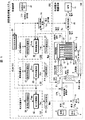
以下、図面を参照しながら詳細に説明する。図1は1実施例による固体酸化物形燃料電池発電システムの構成を示す。燃料電池のセル構造としては、主として円筒型と平板型が提案されているが、両者とも基本的な動作原理は同じであり、以下の実施形態では、円筒型を例にして説明する。また、以下では簡単のため固体酸化物形燃料電池発電システムを単に燃料電池発電システムと呼ぶ。 Hereinafter, it will be described in detail with reference to the drawings. FIG. 1 shows a configuration of a solid oxide fuel cell power generation system according to one embodiment. As a cell structure of the fuel cell, a cylindrical type and a flat plate type are mainly proposed, but both have the same basic operation principle. In the following embodiments, a cylindrical type will be described as an example. In the following, for simplicity, the solid oxide fuel cell power generation system is simply referred to as a fuel cell power generation system.
最初に、本実施形態の燃料電池発電システムのうち、制御装置200を除く破線で示す燃料電池機器本体100の働きについて説明する。
First, the operation of the fuel cell device
まず、燃料1である都市ガス若しくは灯油(以下、単に燃料と呼ぶ)は燃料タンク2より、給水3は給水タンク4より供給される。両者は混合され燃料予熱器5に送られ、給水は蒸気となり、燃料は改質器6にて水素リッチで高温の改質ガス7に転換される。改質ガス7は燃料電池8に送入される。一方、大気から取り込まれた空気9は空気予熱器10にて予熱されたのち燃料電池8に供給される。
First, city gas or kerosene (hereinafter simply referred to as fuel) as
本実施例の燃料電池8は、複数の円筒型セル11で構成され、セルの外側がアノード、内側がカソードになっている。改質ガス7は燃料電池8の下方から送入されアノードに沿って上昇し、上部の燃焼室12に排出される。また、空気は上部のマニホールド13に送入され、ここで複数に分流し、各セルの内部に配置された円筒状の空気導入管14の内部を予熱されながら下降し、下端部を出たのちセル内側のカソードに沿って上昇し、上部の燃焼室12に抜ける。燃焼室12に抜けた空気は、ここでアノードを通過した改質ガス(燃料ガス)と合流する。
The fuel cell 8 of the present embodiment is composed of a plurality of cylindrical cells 11, and the outside of the cell is an anode and the inside is a cathode. The reformed gas 7 is fed from below the fuel cell 8, rises along the anode, and is discharged into the
アノードとカソードの間には解質膜があり、カソード側を通過する空気中の酸素は解質膜の働きでイオン化され電解質を透過してアノードに達し、アノードに供給される改質ガス7に含まれる水素または一酸化炭素と反応することで起電力を発生する。発生した直流電力LCは電力変換器15により交流電力LAに変換され、負荷16に供給される。尚、本図では明示していないが、通常、複数のセルは並列接続と直列接続の組合せで必要な電圧と電流を得ることができるように構成されている。したがって、端子電圧は直列接続セル数に依存し、端子電流は並列接続セル数に依存する。
There is a denatured membrane between the anode and the cathode, and oxygen in the air passing through the cathode side is ionized by the function of the denatured membrane, permeates the electrolyte, reaches the anode, and is supplied to the reformed gas 7 supplied to the anode. An electromotive force is generated by reacting with contained hydrogen or carbon monoxide. The generated DC power L C is converted into AC power L A by the
負荷16が直流電力を要求するものであれば、電力変換器15は直流から交流への変換は不要であるが、端子電圧VCは出力により変化するため、電圧変換機能が必要となる。また、負荷に供給する出力電力LAは電力変換器15における変換損失だけ端子電力LCよりも小さくなる。
If the
燃料1、給水3及び空気9の各流量は、それぞれ燃料流量調整弁17の開度、給水ポンプ18及び空気ブロア19の速度により調整される。改質ガス7はアノードを通過しながら発電に寄与することで燃料濃度が低下するが、ある程度の燃料は残存する。ここで、改質ガス(セル入口ガス)のメタン、水素及び一酸化炭素のモル分率をそれぞれMCH4_in、MH2_in及びMCO_inとし、また、セル出口のそれらをMCH4_out、MH2_out及びMCO_outとすると、燃料利用率UFは次式で定義される。
UF=100×((4MCH4_in+MH2_in+MCO_in)−(4MCH4_out+MH2_out+MCO_out))/ (4MCH4_in+MH2_in+MCO_in) (%)
上式によれば、セル出口においてメタン、水素、一酸化炭素の3成分が全て“零”となったとき燃料消費率UFが100%となり、燃料枯れの状態となる。前述のように通常は85%以下での運転が望ましいとされている。
The flow rates of the
U F = 100 × ((4M CH4_in + M H2_in + M CO_in ) − (4M CH4_out + M H2_out + M CO_out )) / (4M CH4_in + M H2_in + M CO_in ) (%)
According to the above equation, it becomes the fuel consumption rate U F is 100% when the cell outlet methane, hydrogen, 3 components of carbon monoxide becomes all "zero", the fuel withered state. As described above, it is generally considered that operation at 85% or less is desirable.
燃焼室12に排出された空気もある程度の酸素が残存するので、残存燃料と空気は燃焼により再び高温ガスとなり、この高温ガスはマニホールド13に供給された空気を加熱する。燃焼室12から排出された高温ガスは空気予熱器10に送られる。この高温排ガスのエネルギーにより空気が予熱されマニホールド13に送入される。さらに、空気予熱器10からの排出ガスも燃料予熱器5と改質器6に導かれ、燃料の予熱と改質に利用されたのち排ガスブロア20によりシステム外に排出される。
Since a certain amount of oxygen remains in the air discharged into the
このように、排熱を回収して再利用する理由は、燃料電池8において一定以上の効率を維持して安定な発電をするためには、アノード側出口の燃料とカソード側出口の酸素を一定以上の濃度に保つことが必要となるからである。そのため、供給された燃料と酸素の全てを発電に使わず、或る程度の燃料と酸素を残して燃焼室12に排出することになる。
As described above, the reason for recovering and reusing the waste heat is that the fuel at the anode side outlet and the oxygen at the cathode side outlet are kept constant in order to maintain a certain level of efficiency and generate stable power in the fuel cell 8. This is because it is necessary to maintain the above concentration. Therefore, not all of the supplied fuel and oxygen are used for power generation, but a certain amount of fuel and oxygen is left and discharged to the
次に、制御装置200の構成と動作について説明する。図1の二点鎖線で囲んだ制御装置200において、太線で示す制御要素が本発明の実施形態に係るもので、細線で示す制御要素は従来システムと共通するものである。ここでは制御装置の働きを理解し易くするために各制御要素をブロックで示したが、実際には燃料電池機器本体100と同一パッケージ内、若しくはその近傍に配置されたコントローラで実現されている。
Next, the configuration and operation of the
まず、従来要素の働きについて説明する。制御装置200において目標出力設定手段21から目標出力指令値LROが発せられる。この目標出力指令値LROに対応して、基準燃料流量指令手段22では基準燃料流量指令値FFR0、基準給水流量指令手段24では基準給水流量指令値FWR0、及び基準空気流量指令手段26では基準空気流量指令値FAR0が出力される。この3つの基準指令値FFR0、FWR0、FAR0は、静特性的に設計条件に合致するバランス条件であり、定常運転時に出力LROを得るのに必要な値である。
First, the function of the conventional element will be described. In the
基準燃料流量指令値FFR0は後述する燃料流量補正手段30により燃料補正値FFMが加算されて補正後燃料流量指令値FFRとなり、これが弁開度指令手段27に与えられ、燃料流量調整弁17に対する弁開度指令値AFVを出力する。また、基準給水流量指令値FWR0は後述する給水流量補正手段40により給水補正値FWMが加算されて補正後給水流量指令値FWRとなり、これがポンプ速度指令手段25に与えられ、これに対応して給水ポンプ18に速度指令値NWPを出力する。さらに、基準空気流量指令値FAR0は後述する空気流量補正手段60により空気補正値FAMが加算されて補正後空気流量指令値FARとなり、これがブロア速度指令手段23に与えられ、これに対応して空気ブロア19にブロア速度指令値NABを出力する。
The reference fuel flow rate command value F FR0 is added with a fuel correction value F FM by a fuel flow rate correction means 30 to be described later to obtain a corrected fuel flow rate command value F FR , which is given to the valve opening degree command means 27 to be a fuel flow rate adjustment valve. The valve opening command value A FV for 17 is output. The reference feed water flow rate command value F WR0 is feed water flow water correction value F WM is added by the correction means 40 by the corrected feed water flow rate command value F WR next to be described later, which is given to the pump speed command means 25, correspondingly Then, the speed command value N WP is output to the
一方、目標出力指令値LR0は電力変換制御手段28に与えられる。電力変換器制御手段28では、これを満たすような電流指令値ICRを電力変換器15に指令する。即ち、電力変換制御手段28では燃料電池8の端子電圧VCを入力して、ICR(=LR0/ηEVC)なる電流指令値ICRを発生する。ここで、ηEは電力変換器15の変換効率であり、前述のように変換損失分を勘案したものである。また、セルの並列数をnPとすると、セル電流ICはICR/nPとなる。
On the other hand, the target output command value L R0 is given to the power conversion control means 28. The power converter control means 28 commands the
次に、本発明の特徴部に係る制御装置200における制御要素について説明する。図1に示した燃料流量補正手段30、給水流量補正手段40及び燃料流量補正手段60の具体的な実施形態について、それぞれ図2、図3、図4を用いて順に説明する。
Next, control elements in the
図2は燃料流量補正手段の構成を示す。燃料補正手段30は、出力変化率演算手段29より算出された出力変化率(dLR0/dt)を入力する。この変化率に比例ゲイン31(−KF)を掛けた値に2次遅れ特性32を与え、得られた燃料補正値FFMが前記基準燃料流量指令値FFR0に加算手段33にて加算されて補正後の燃料流量指令値FFRとなる。
FIG. 2 shows the configuration of the fuel flow rate correcting means. The
ここで、比例ゲイン31を負にした理由は、出力変化率(dLR0/dt)が負になる出力降下時は燃料流量を増強し、正となる出力上昇時は燃料流量を抑制することを意図している。これにより、出力降下時は改質率の上昇とそれに伴う燃料利用率の上昇を抑制する効果があり、出力上昇時は改質率の低下とそれに伴う燃料利用率の低下を抑制する効果がある。これらの効果は、改質器6における燃料ガスの滞留時間変動とこれに伴う改質率の変動が抑制されることで実現している。また、燃料補正値FFMとして2次遅れ特性を与えた理由は、燃料流量を出力変化に過度に反応させないためと、出力変化終了後の改質器6の温度が安定値に向かう速度に合わせることで改質率を安定化させるためである。このときの遅れ時定数TFはシステム動特性に応じて適宜設定すれば良い。
Here, the reason why the
図3は給水量補正手段の構成を示す。給水流量補正手段40は、出力変化率演算手段29より算出された出力変化率(dLR0/dt)を入力する。この変化率に比例ゲイン34(−KW)を掛けた値を2次遅れ特性演算手段35に与え、得られた給水補正値FWMが加算手段36により基準給水流量指令値FWR0に加算されて補正後の給水流量指令値FWRとなる。比例ゲイン34を負にした理由は、燃料流量補正手段30の場合と同様、出力変化率(dLR0/dt)が負になる出力降下時は給水流量を増強し、正となる出力上昇時は給水流量を抑制することを意図している。これにより、同様の効果、即ち、出力変動時の改質器6における燃料ガスの滞留時間変動を抑制し、これに伴う改質率の変動と燃料利用率の変動を抑制している。また、給水補正値FWMとして2次遅れ特性を与えた理由も、燃料流量と同様に給水流量を出力変化に過度に反応させないためと、出力変化終了後も改質率を安定化させるためである。このときの遅れ時定数TWもシステム動特性に応じて適宜設定すれば良い。
FIG. 3 shows the configuration of the water supply amount correction means. The feed water flow rate correcting means 40 inputs the output change rate (dL R0 / dt) calculated by the output change rate calculating means 29. A value obtained by multiplying the rate of change by the proportional gain 34 (−K W ) is given to the second-order lag characteristic calculating means 35, and the obtained water supply correction value F WM is added to the reference water supply flow rate command value F WR0 by the adding means 36. The corrected feed water flow rate command value F WR is obtained. The reason why the proportional gain 34 is made negative is the same as in the case of the fuel flow rate correction means 30, when the output change rate (dL R0 / dt) is negative, the feed water flow rate is increased, and when the output increase becomes positive. It is intended to control the water supply flow rate. As a result, the same effect, that is, the fluctuation in the residence time of the fuel gas in the
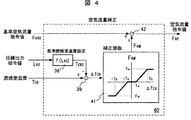
図4は空気流量補正手段の構成を示す。空気流量補正手段60は、まず、目標出力指令値LR0と温度計37で計測した燃焼室温度TCBを入力する。目標出力指令値LR0に対応して基準燃焼室温度設定手段38で基準燃焼室温度TCBSを決定し、燃焼室温度TCBとの温度偏差ΔTCBを減算手段39により求める。次に、補正関数発生手段41により、温度偏差ΔTCBに対応した空気補正値FAMが求められ、加算手段42により基準空気流量指令値FAR0に加算されて補正後の空気流量指令値FARとなる。
FIG. 4 shows the configuration of the air flow rate correcting means. First, the air flow rate correction means 60 inputs the target output command value L R0 and the combustion chamber temperature T CB measured by the
ここで、基準燃焼室温度設定手段38で決められる基準燃焼室温度TCBSとは、システムの静特性バランスとして適切な燃焼室温度であり、定常状態では燃焼室12を出たあとの排ガスにより空気予熱器10、燃料予熱器5、改質器6の運転状態が影響を受ける。補正関数41による空気補正は、目標出力指令値LR0に従って出力が変動する場合は、基準燃焼室温度TCBSに燃焼室温度に追従できるようにするためのものである。即ち、実際の燃焼室温度TCBが基準燃焼室温度TCBSよりも高くなったときは、空気流量を増やして温度を下げる働きをし、燃焼室温度TCBが下がった場合は逆に空気流量を減らす動作となる。これにより、燃料流量補正手段30と空気流量補正手段40が動作したときの影響も吸収され燃焼室温度TCBは安定に保つことができる。補正関数41としては温度偏差ΔTCBに対してデッドバンド(不感帯)±Taを設けているが、これは燃焼室12での流動ムラや燃焼ムラなどにより燃焼室温度TCBの僅かな温度変動があっても空気流量を変えないためである。
Here, the reference combustion chamber temperature T CBS determined by the reference combustion chamber temperature setting means 38 is an appropriate combustion chamber temperature as a static characteristic balance of the system, and in a steady state, air is generated by exhaust gas after leaving the
図5は制御装置の動作による各部の出力の時間経過を示すタイミングチャートである。本図はシミュレーションによって得たもので、時刻t1からt2の間で目標出力指令値LR0を一定変化率で降下させ、時刻t3からt4の間では、逆に目標出力指令値LR0を一定変化率で上昇させた場合を示す。出力変化率(dLR0/dt)はステップ状に変化して、t1からt2の出力降下時は負方向の矩形状となり、t3からt4の出力上昇時は正方向の矩形状となっている。燃料補正値FFMと給水補正値FWMは出力変化率(dLR0/dt)に比例し、かつ2次遅れ特性を示す。これら補正値FFM、FWMが各々の基準値FFR0、FWR0に加算されて実際の指令値FFR、FWRとなっている。従って、出力変化時の指令値の変化は両者とも基準値の変化より小さく、出力変化後は徐々に基準値まで復帰している。 FIG. 5 is a timing chart showing the time lapse of the output of each part due to the operation of the control device. This figure is obtained by simulation, and the target output command value L R0 is decreased at a constant rate of change from time t 1 to t 2 , and conversely between time t 3 and t 4 The case where R0 is increased at a constant rate of change is shown. Output change rate (dL R0 / dt) is changed stepwise, the output drop during t 2 from t 1 becomes a negative direction of the rectangular, rising output from t 3 t 4 is the positive direction of the rectangular It has become. The fuel correction value F FM and the water supply correction value F WM are proportional to the output change rate (dL R0 / dt) and exhibit a second-order lag characteristic. These correction values F FM and F WM are added to the respective reference values F FR0 and F WR0 to obtain actual command values F FR and F WR . Therefore, the change in the command value at the time of output change is smaller than the change in the reference value, and after the output change, it gradually returns to the reference value.
一方、燃焼室温度TCBについては、基準燃焼室温度設定値TCBSが出力指令値に応じて変更されている。実際の燃焼室温度TCBは基準燃焼室温度設定値TCBSよりも大きく変動する傾向を示すが、本発明によると実際の燃焼室温度TCBと基準値TCBSとの温度偏差ΔTCBに応じて空気量補正値FAMが基準空気流量指令値FAR0に加算されるため、実際の燃焼室温度TCBの変動は抑制されている。即ち、出力降下時は燃焼室温度TCBの低下が抑制され、出力上昇時は燃焼室温度TCBの上昇が抑制される。 On the other hand, for the combustion chamber temperature T CB , the reference combustion chamber temperature set value T CBS is changed according to the output command value. Although the actual combustion chamber temperature T CB tends to fluctuate more than the reference combustion chamber temperature set value T CBS , according to the present invention, the actual combustion chamber temperature T CB depends on the temperature deviation ΔT CB between the actual combustion chamber temperature T CB and the reference value T CBS. Thus, since the air amount correction value F AM is added to the reference air flow rate command value F AR0 , the actual fluctuation of the combustion chamber temperature T CB is suppressed. That is, when the output decreases, the decrease in the combustion chamber temperature T CB is suppressed, and when the output increases, the increase in the combustion chamber temperature T CB is suppressed.
以上の結果、本図に示すように改質率RFの変動が抑制され、その結果、燃料利用率UFも安定化されている。 As a result, fluctuations in the reforming rate R F are suppressed as shown in the figure, and as a result, the fuel utilization rate U F is also stabilized.
以上のように、本実施形態によれば、固体酸化物形燃料電池発電システムの出力変化時の燃料利用率を安定化できるため燃料枯れを回避でき、アノードの酸化による電池性能の劣化を防止できる。そのため、電池の耐久性が増し、長期に亘り高効率と高稼働率を維持できる。これにより燃料費や保守費を最小限にできるため、運用コストを大幅に低減することが可能となる。 As described above, according to the present embodiment, the fuel utilization rate at the time of output change of the solid oxide fuel cell power generation system can be stabilized, so that fuel withering can be avoided, and deterioration of the cell performance due to anode oxidation can be prevented. . Therefore, the durability of the battery is increased, and high efficiency and high operation rate can be maintained over a long period of time. As a result, the fuel cost and the maintenance cost can be minimized, so that the operation cost can be greatly reduced.
なお、本発明は上述の実施形態に限定されるものでなく、以下に述べる実施形態においても、その本質を何ら変えることなく適用可能である。 In addition, this invention is not limited to the above-mentioned embodiment, It can apply, without changing the essence in the embodiment described below.
まず、本発明の実施形態では燃料利用率安定化のための補正手段として、燃料補正値、給水補正値、空気補正値の3つの手段を用いる方法とした。しかし、必ずしも3つの手段を用いる必要はなく、システム構成や設計条件に応じて、これらの1つ、若しくは2つを適宜選択して実施する方法としても、本発明の本質を何ら変えるものではない。特に、燃料補正値と給水補正値を用いる方法は有効である。 First, in the embodiment of the present invention, as a correction means for stabilizing the fuel utilization rate, a method using three means of a fuel correction value, a water supply correction value, and an air correction value is used. However, it is not always necessary to use three means, and the essence of the present invention is not changed at all even if one or two of these methods are appropriately selected according to the system configuration and design conditions. . In particular, the method using the fuel correction value and the water supply correction value is effective.
また、本発明の実施形態では燃料補正値と給水補正値を出力変化率に基づいて算出しているが、必ずしも出力変化率を用いなくても、これに順ずるものであれば良く、例えば電流値変化率を用いる方法としても本発明の本質を何ら変えることなく適用可能である。 Further, in the embodiment of the present invention, the fuel correction value and the water supply correction value are calculated based on the output change rate, but it is not always necessary to use the output change rate. The method using the value change rate can be applied without changing the essence of the present invention.
さらに、本発明の実施形態では燃料電池のセル構造として円筒型のものを対象としたが、本発明を適用するに当り円筒型セルに限定する必要はなく、平板型セルやその他の構造を持つセルに対しても、本発明の本質を何ら変更されることなく実施できる。 Furthermore, in the embodiment of the present invention, the cylindrical cell structure is targeted for the fuel cell, but it is not necessary to limit the present invention to the cylindrical cell, and it has a flat cell or other structure. The essence of the present invention can be applied to the cell without any change.
また、本発明の実施形態は燃料電池システムのセル構造として、円筒の内側がアノード、外側がアノードとするものを対象としたが、この逆でもよい。即ち内側がアノード、外側がカソードとするセル構造を有する燃料電池システムに対しても、本発明の本質を何ら変更されることなく実施できる。 In addition, although the embodiment of the present invention is directed to the cell structure of the fuel cell system, the inside of the cylinder is the anode and the outside is the anode, but the reverse is also possible. That is, the essence of the present invention can be applied to a fuel cell system having a cell structure having an anode on the inside and a cathode on the outside without any change.
また、本発明の実施形態では燃料補正値と給水補正値の算出に、2次遅れ特性を用いる方法としたが、必ずしも2次遅れ特性とする必要はない。例えば、1次遅れ特性やランプ関数などで燃料補正値FFMを柔軟に変更する方法であれば、燃料利用率の変動を抑制するという本発明の本質は変わらない。 In the embodiment of the present invention, the second-order lag characteristic is used for calculating the fuel correction value and the water supply correction value. However, the second-order lag characteristic is not necessarily required. For example, if the fuel correction value FFM is flexibly changed using a first-order lag characteristic, a ramp function, or the like, the essence of the present invention that suppresses fluctuations in the fuel utilization rate remains the same.
さらに、本発明の実施形態では空気流量補正用の補正関数41において、補正感度Fmや補正の有効域Tbを規定している。この補正関数はシステムの設計条件に応じて、例えば、3次曲線や比例積分演算など適宜採用した方法としても、燃焼室温度を安定化させることで燃料利用率を安定化するという本発明の本質は変わらない。
Furthermore, in the embodiment of the present invention, the correction sensitivity Fm and the effective correction area Tb are defined in the
また、本発明の実施形態では空気流量補正のために燃焼室温度を用いたが、必ずしも燃焼室温度に着目する必要はなく、これに順ずるものであれば良い。例えば、燃焼室を出たあとの排ガス温度を用いる方法としても本発明の本質を何ら変えることなく適用可能である。 Further, in the embodiment of the present invention, the combustion chamber temperature is used for air flow correction. However, it is not always necessary to pay attention to the combustion chamber temperature, and it is only necessary to follow this. For example, the method using the exhaust gas temperature after leaving the combustion chamber can be applied without changing the essence of the present invention.
さらに、本発明の実施形態では排ガスが空気予熱器、燃料予熱器、改質器の順次に供給されるシステム構成としているが、必ずしもこの構成とする必要はない。例えば、排ガスが改質器を通過してから燃料予熱器に供給されたり、給水蒸発器を別途配置されたりしたシステム構成であっても、本発明の本質を何ら変えることなく適用可能である。 Furthermore, in the embodiment of the present invention, the system configuration is such that the exhaust gas is sequentially supplied to the air preheater, the fuel preheater, and the reformer, but this configuration is not necessarily required. For example, a system configuration in which exhaust gas is supplied to the fuel preheater after passing through the reformer or a feed water evaporator is separately arranged can be applied without changing the essence of the present invention.
1…燃料、2…燃料タンク、3…給水、4…給水タンク、5…燃料予熱器、6…改質器、7…改質ガス、8…燃料電池、9…空気、10…空気予熱器、11…セル、12…燃焼室、13…マニホールド、14…空気導入管、15…電力変換器、16…負荷、17…燃料流量調整弁、18…給水ポンプ、19…空気ブロア、20…排ガスブロア、21…目標出力設定手段、23…ブロア速度指令手段、25…ポンプ速度指令手段、27…弁開度指令手段、28…電力変換器制御手段、29…出力変化率演算手段、22…基準燃料流量指令手段、24…基準給水流量指令手段、26…基準空気流量指令手段、30…燃料流量補正手段、40…給水流流量補正手段、60…空気流量補正手段、31…比例ゲイン、32…2次遅れ特性演算手段、33…加算手段、34…比例ゲイン、35…2次遅れ特性演算手段、36…加算手段、37…温度計、38…基準燃焼室温度設定手段、39…減算手段、41…補正関数、42…加算手段、100…燃料電池機器本体、200…制御装置、50…燃料流量制御手段、150…給水流量制御手段、250…空気流量制御手段。
DESCRIPTION OF
Claims (8)
Priority Applications (1)
| Application Number | Priority Date | Filing Date | Title |
|---|---|---|---|
| JP2006349432A JP4944597B2 (en) | 2006-12-26 | 2006-12-26 | Solid oxide fuel cell power generation system and operation control method thereof |
Applications Claiming Priority (1)
| Application Number | Priority Date | Filing Date | Title |
|---|---|---|---|
| JP2006349432A JP4944597B2 (en) | 2006-12-26 | 2006-12-26 | Solid oxide fuel cell power generation system and operation control method thereof |
Publications (2)
| Publication Number | Publication Date |
|---|---|
| JP2008159517A JP2008159517A (en) | 2008-07-10 |
| JP4944597B2 true JP4944597B2 (en) | 2012-06-06 |
Family
ID=39660182
Family Applications (1)
| Application Number | Title | Priority Date | Filing Date |
|---|---|---|---|
| JP2006349432A Expired - Fee Related JP4944597B2 (en) | 2006-12-26 | 2006-12-26 | Solid oxide fuel cell power generation system and operation control method thereof |
Country Status (1)
| Country | Link |
|---|---|
| JP (1) | JP4944597B2 (en) |
Families Citing this family (5)
| Publication number | Priority date | Publication date | Assignee | Title |
|---|---|---|---|---|
| JP5244504B2 (en) * | 2008-08-28 | 2013-07-24 | 株式会社日立製作所 | Solid oxide fuel cell system and operation method thereof |
| JP2011076933A (en) * | 2009-09-30 | 2011-04-14 | Toto Ltd | Solid oxide fuel cell system |
| JP5783370B2 (en) * | 2011-09-29 | 2015-09-24 | Toto株式会社 | Solid oxide fuel cell |
| WO2013061513A1 (en) * | 2011-10-24 | 2013-05-02 | パナソニック株式会社 | Fuel cell system and method for operating same |
| CN117096388B (en) * | 2023-10-18 | 2023-12-15 | 上海氢晨新能源科技有限公司 | Fuel cell water content management control method, electric equipment and electronic equipment |
Family Cites Families (6)
| Publication number | Priority date | Publication date | Assignee | Title |
|---|---|---|---|---|
| JPH0789495B2 (en) * | 1984-10-25 | 1995-09-27 | 株式会社東芝 | Fuel cell power plant |
| JP3738744B2 (en) * | 2002-04-01 | 2006-01-25 | 日産自動車株式会社 | Fuel reforming control system |
| JP4108385B2 (en) * | 2002-06-27 | 2008-06-25 | 株式会社日本自動車部品総合研究所 | Fuel reformer |
| JP4246053B2 (en) * | 2003-12-17 | 2009-04-02 | 日本電信電話株式会社 | Starting method of fuel cell power generation system |
| JP4721650B2 (en) * | 2004-03-25 | 2011-07-13 | 株式会社日立製作所 | Solid polymer fuel cell power generation system and household distributed power supply system |
| JP4331125B2 (en) * | 2005-03-03 | 2009-09-16 | 東京瓦斯株式会社 | Operation control method and system for solid oxide fuel cell |
-
2006
- 2006-12-26 JP JP2006349432A patent/JP4944597B2/en not_active Expired - Fee Related
Also Published As
| Publication number | Publication date |
|---|---|
| JP2008159517A (en) | 2008-07-10 |
Similar Documents
| Publication | Publication Date | Title |
|---|---|---|
| US8435691B2 (en) | Operation method at the time of load increase of fuel cell system | |
| US20050233188A1 (en) | Fuel cell operation method | |
| JP4944597B2 (en) | Solid oxide fuel cell power generation system and operation control method thereof | |
| JP6215564B2 (en) | Method and adjusting device for adjusting a fuel cell or fuel cell stack | |
| JP2008103198A (en) | Solid oxide fuel cell power generation system, and its operation control method | |
| JP2010212141A (en) | Fuel cell generator | |
| KR20190016037A (en) | Fuel cell load cycling to support the power grid | |
| CN103299467B (en) | For controlling the method and apparatus of the fuel supply in fuel cell system | |
| JP2009081052A (en) | Solid oxide fuel cell power generation system and operation control method of solid oxide fuel cell power generation system | |
| JP2013527555A (en) | How to operate a cogeneration facility | |
| JP4325270B2 (en) | Operation control method of fuel cell power generator | |
| CN101416339B (en) | Fuel cell system and control method thereof | |
| JP2009277525A (en) | Solid oxide fuel cell cogeneration system and its operation control method | |
| US9105895B2 (en) | Operation method at the time of load reduction of fuel cell system | |
| JP2671523B2 (en) | Operation control method for fuel cell power generator | |
| JP2007194005A (en) | Solid oxide fuel cell power generation system and its operation control method | |
| JP2009238623A (en) | Solid oxide fuel cell power generation system and its operation control method | |
| KR101656993B1 (en) | Real time load following type fuel cell system and method of controlling the same | |
| JP2001325975A (en) | Fuel cell power generation apparatus and its control method | |
| JP3808636B2 (en) | Fuel cell power generation system and power generation system | |
| JP2009238622A (en) | Solid oxide fuel cell power generation system and its operation control method | |
| JPH0676846A (en) | Operation control device for fuel cell power generating device | |
| JP4176354B2 (en) | Fuel and water supply control device, fuel and water supply control method, and power supply system | |
| JP2006331761A (en) | Fuel cell power generation system | |
| JP5922435B2 (en) | Fuel cell system and control method thereof |
Legal Events
| Date | Code | Title | Description |
|---|---|---|---|
| A621 | Written request for application examination |
Free format text: JAPANESE INTERMEDIATE CODE: A621 Effective date: 20081017 |
|
| A131 | Notification of reasons for refusal |
Free format text: JAPANESE INTERMEDIATE CODE: A131 Effective date: 20111206 |
|
| A521 | Written amendment |
Free format text: JAPANESE INTERMEDIATE CODE: A523 Effective date: 20120206 |
|
| TRDD | Decision of grant or rejection written | ||
| A01 | Written decision to grant a patent or to grant a registration (utility model) |
Free format text: JAPANESE INTERMEDIATE CODE: A01 Effective date: 20120228 |
|
| A01 | Written decision to grant a patent or to grant a registration (utility model) |
Free format text: JAPANESE INTERMEDIATE CODE: A01 |
|
| A61 | First payment of annual fees (during grant procedure) |
Free format text: JAPANESE INTERMEDIATE CODE: A61 Effective date: 20120302 |
|
| R150 | Certificate of patent or registration of utility model |
Free format text: JAPANESE INTERMEDIATE CODE: R150 |
|
| FPAY | Renewal fee payment (event date is renewal date of database) |
Free format text: PAYMENT UNTIL: 20150309 Year of fee payment: 3 |
|
| LAPS | Cancellation because of no payment of annual fees |