JP2013527555A - How to operate a cogeneration facility - Google Patents
How to operate a cogeneration facility Download PDFInfo
- Publication number
- JP2013527555A JP2013527555A JP2012549316A JP2012549316A JP2013527555A JP 2013527555 A JP2013527555 A JP 2013527555A JP 2012549316 A JP2012549316 A JP 2012549316A JP 2012549316 A JP2012549316 A JP 2012549316A JP 2013527555 A JP2013527555 A JP 2013527555A
- Authority
- JP
- Japan
- Prior art keywords
- fuel
- fuel cell
- heat
- facility
- additional heater
- Prior art date
- Legal status (The legal status is an assumption and is not a legal conclusion. Google has not performed a legal analysis and makes no representation as to the accuracy of the status listed.)
- Pending
Links
- 239000000446 fuel Substances 0.000 claims abstract description 271
- 238000000034 method Methods 0.000 claims abstract description 28
- XLYOFNOQVPJJNP-UHFFFAOYSA-N water Substances O XLYOFNOQVPJJNP-UHFFFAOYSA-N 0.000 claims description 24
- 229910001868 water Inorganic materials 0.000 claims description 24
- 238000010438 heat treatment Methods 0.000 claims description 19
- 238000009434 installation Methods 0.000 claims description 4
- 230000001105 regulatory effect Effects 0.000 claims description 2
- VNWKTOKETHGBQD-UHFFFAOYSA-N methane Chemical compound C VNWKTOKETHGBQD-UHFFFAOYSA-N 0.000 description 20
- UFHFLCQGNIYNRP-UHFFFAOYSA-N Hydrogen Chemical compound [H][H] UFHFLCQGNIYNRP-UHFFFAOYSA-N 0.000 description 9
- 239000001257 hydrogen Substances 0.000 description 9
- 229910052739 hydrogen Inorganic materials 0.000 description 9
- 239000003345 natural gas Substances 0.000 description 9
- 238000002485 combustion reaction Methods 0.000 description 8
- 230000015556 catabolic process Effects 0.000 description 7
- 238000006731 degradation reaction Methods 0.000 description 7
- 239000007789 gas Substances 0.000 description 7
- 239000007800 oxidant agent Substances 0.000 description 6
- 230000001590 oxidative effect Effects 0.000 description 5
- UGFAIRIUMAVXCW-UHFFFAOYSA-N Carbon monoxide Chemical compound [O+]#[C-] UGFAIRIUMAVXCW-UHFFFAOYSA-N 0.000 description 4
- 229910002091 carbon monoxide Inorganic materials 0.000 description 4
- 230000006866 deterioration Effects 0.000 description 4
- 239000012530 fluid Substances 0.000 description 4
- 238000010248 power generation Methods 0.000 description 4
- OKKJLVBELUTLKV-UHFFFAOYSA-N Methanol Chemical compound OC OKKJLVBELUTLKV-UHFFFAOYSA-N 0.000 description 3
- 230000008901 benefit Effects 0.000 description 3
- 238000004891 communication Methods 0.000 description 3
- 230000007423 decrease Effects 0.000 description 3
- 238000009826 distribution Methods 0.000 description 3
- 238000005516 engineering process Methods 0.000 description 3
- 238000004519 manufacturing process Methods 0.000 description 3
- CURLTUGMZLYLDI-UHFFFAOYSA-N Carbon dioxide Chemical compound O=C=O CURLTUGMZLYLDI-UHFFFAOYSA-N 0.000 description 2
- 206010016334 Feeling hot Diseases 0.000 description 2
- ATUOYWHBWRKTHZ-UHFFFAOYSA-N Propane Chemical compound CCC ATUOYWHBWRKTHZ-UHFFFAOYSA-N 0.000 description 2
- QVGXLLKOCUKJST-UHFFFAOYSA-N atomic oxygen Chemical compound [O] QVGXLLKOCUKJST-UHFFFAOYSA-N 0.000 description 2
- 238000006243 chemical reaction Methods 0.000 description 2
- 230000001419 dependent effect Effects 0.000 description 2
- 239000000463 material Substances 0.000 description 2
- 238000005259 measurement Methods 0.000 description 2
- 239000001301 oxygen Substances 0.000 description 2
- 229910052760 oxygen Inorganic materials 0.000 description 2
- 230000026280 response to electrical stimulus Effects 0.000 description 2
- 239000004215 Carbon black (E152) Substances 0.000 description 1
- LFQSCWFLJHTTHZ-UHFFFAOYSA-N Ethanol Chemical compound CCO LFQSCWFLJHTTHZ-UHFFFAOYSA-N 0.000 description 1
- 230000009471 action Effects 0.000 description 1
- 230000002411 adverse Effects 0.000 description 1
- 229910002092 carbon dioxide Inorganic materials 0.000 description 1
- 239000001569 carbon dioxide Substances 0.000 description 1
- 230000008859 change Effects 0.000 description 1
- 230000006835 compression Effects 0.000 description 1
- 238000007906 compression Methods 0.000 description 1
- 238000010586 diagram Methods 0.000 description 1
- 238000000605 extraction Methods 0.000 description 1
- 239000000295 fuel oil Substances 0.000 description 1
- 239000003502 gasoline Substances 0.000 description 1
- 230000020169 heat generation Effects 0.000 description 1
- 238000005338 heat storage Methods 0.000 description 1
- 229930195733 hydrocarbon Natural products 0.000 description 1
- 150000002430 hydrocarbons Chemical class 0.000 description 1
- 239000003350 kerosene Substances 0.000 description 1
- 239000007788 liquid Substances 0.000 description 1
- 230000007774 longterm Effects 0.000 description 1
- 230000002028 premature Effects 0.000 description 1
- 230000008569 process Effects 0.000 description 1
- -1 propane Chemical class 0.000 description 1
- 239000001294 propane Substances 0.000 description 1
- 239000000376 reactant Substances 0.000 description 1
- 238000011084 recovery Methods 0.000 description 1
- 238000002407 reforming Methods 0.000 description 1
- 238000007086 side reaction Methods 0.000 description 1
- 239000007787 solid Substances 0.000 description 1
- 239000000126 substance Substances 0.000 description 1
- 230000032258 transport Effects 0.000 description 1
Images


Classifications
-
- F—MECHANICAL ENGINEERING; LIGHTING; HEATING; WEAPONS; BLASTING
- F24—HEATING; RANGES; VENTILATING
- F24D—DOMESTIC- OR SPACE-HEATING SYSTEMS, e.g. CENTRAL HEATING SYSTEMS; DOMESTIC HOT-WATER SUPPLY SYSTEMS; ELEMENTS OR COMPONENTS THEREFOR
- F24D19/00—Details
- F24D19/10—Arrangement or mounting of control or safety devices
- F24D19/1006—Arrangement or mounting of control or safety devices for water heating systems
- F24D19/1009—Arrangement or mounting of control or safety devices for water heating systems for central heating
-
- F—MECHANICAL ENGINEERING; LIGHTING; HEATING; WEAPONS; BLASTING
- F24—HEATING; RANGES; VENTILATING
- F24D—DOMESTIC- OR SPACE-HEATING SYSTEMS, e.g. CENTRAL HEATING SYSTEMS; DOMESTIC HOT-WATER SUPPLY SYSTEMS; ELEMENTS OR COMPONENTS THEREFOR
- F24D11/00—Central heating systems using heat accumulated in storage masses
- F24D11/002—Central heating systems using heat accumulated in storage masses water heating system
-
- F—MECHANICAL ENGINEERING; LIGHTING; HEATING; WEAPONS; BLASTING
- F24—HEATING; RANGES; VENTILATING
- F24D—DOMESTIC- OR SPACE-HEATING SYSTEMS, e.g. CENTRAL HEATING SYSTEMS; DOMESTIC HOT-WATER SUPPLY SYSTEMS; ELEMENTS OR COMPONENTS THEREFOR
- F24D18/00—Small-scale combined heat and power [CHP] generation systems specially adapted for domestic heating, space heating or domestic hot-water supply
-
- F—MECHANICAL ENGINEERING; LIGHTING; HEATING; WEAPONS; BLASTING
- F24—HEATING; RANGES; VENTILATING
- F24H—FLUID HEATERS, e.g. WATER OR AIR HEATERS, HAVING HEAT-GENERATING MEANS, e.g. HEAT PUMPS, IN GENERAL
- F24H15/00—Control of fluid heaters
- F24H15/20—Control of fluid heaters characterised by control inputs
- F24H15/212—Temperature of the water
-
- F—MECHANICAL ENGINEERING; LIGHTING; HEATING; WEAPONS; BLASTING
- F24—HEATING; RANGES; VENTILATING
- F24H—FLUID HEATERS, e.g. WATER OR AIR HEATERS, HAVING HEAT-GENERATING MEANS, e.g. HEAT PUMPS, IN GENERAL
- F24H15/00—Control of fluid heaters
- F24H15/20—Control of fluid heaters characterised by control inputs
- F24H15/258—Outdoor temperature
-
- F—MECHANICAL ENGINEERING; LIGHTING; HEATING; WEAPONS; BLASTING
- F24—HEATING; RANGES; VENTILATING
- F24H—FLUID HEATERS, e.g. WATER OR AIR HEATERS, HAVING HEAT-GENERATING MEANS, e.g. HEAT PUMPS, IN GENERAL
- F24H15/00—Control of fluid heaters
- F24H15/30—Control of fluid heaters characterised by control outputs; characterised by the components to be controlled
- F24H15/305—Control of valves
-
- F—MECHANICAL ENGINEERING; LIGHTING; HEATING; WEAPONS; BLASTING
- F24—HEATING; RANGES; VENTILATING
- F24H—FLUID HEATERS, e.g. WATER OR AIR HEATERS, HAVING HEAT-GENERATING MEANS, e.g. HEAT PUMPS, IN GENERAL
- F24H15/00—Control of fluid heaters
- F24H15/30—Control of fluid heaters characterised by control outputs; characterised by the components to be controlled
- F24H15/335—Control of pumps, e.g. on-off control
-
- F—MECHANICAL ENGINEERING; LIGHTING; HEATING; WEAPONS; BLASTING
- F24—HEATING; RANGES; VENTILATING
- F24H—FLUID HEATERS, e.g. WATER OR AIR HEATERS, HAVING HEAT-GENERATING MEANS, e.g. HEAT PUMPS, IN GENERAL
- F24H15/00—Control of fluid heaters
- F24H15/30—Control of fluid heaters characterised by control outputs; characterised by the components to be controlled
- F24H15/375—Control of heat pumps
- F24H15/38—Control of compressors of heat pumps
-
- H—ELECTRICITY
- H01—ELECTRIC ELEMENTS
- H01M—PROCESSES OR MEANS, e.g. BATTERIES, FOR THE DIRECT CONVERSION OF CHEMICAL ENERGY INTO ELECTRICAL ENERGY
- H01M8/00—Fuel cells; Manufacture thereof
- H01M8/04—Auxiliary arrangements, e.g. for control of pressure or for circulation of fluids
- H01M8/04298—Processes for controlling fuel cells or fuel cell systems
- H01M8/04694—Processes for controlling fuel cells or fuel cell systems characterised by variables to be controlled
- H01M8/04746—Pressure; Flow
- H01M8/04753—Pressure; Flow of fuel cell reactants
-
- H—ELECTRICITY
- H01—ELECTRIC ELEMENTS
- H01M—PROCESSES OR MEANS, e.g. BATTERIES, FOR THE DIRECT CONVERSION OF CHEMICAL ENERGY INTO ELECTRICAL ENERGY
- H01M8/00—Fuel cells; Manufacture thereof
- H01M8/06—Combination of fuel cells with means for production of reactants or for treatment of residues
- H01M8/0662—Treatment of gaseous reactants or gaseous residues, e.g. cleaning
-
- F—MECHANICAL ENGINEERING; LIGHTING; HEATING; WEAPONS; BLASTING
- F24—HEATING; RANGES; VENTILATING
- F24D—DOMESTIC- OR SPACE-HEATING SYSTEMS, e.g. CENTRAL HEATING SYSTEMS; DOMESTIC HOT-WATER SUPPLY SYSTEMS; ELEMENTS OR COMPONENTS THEREFOR
- F24D2101/00—Electric generators of small-scale CHP systems
- F24D2101/30—Fuel cells
-
- F—MECHANICAL ENGINEERING; LIGHTING; HEATING; WEAPONS; BLASTING
- F24—HEATING; RANGES; VENTILATING
- F24D—DOMESTIC- OR SPACE-HEATING SYSTEMS, e.g. CENTRAL HEATING SYSTEMS; DOMESTIC HOT-WATER SUPPLY SYSTEMS; ELEMENTS OR COMPONENTS THEREFOR
- F24D2103/00—Thermal aspects of small-scale CHP systems
- F24D2103/10—Small-scale CHP systems characterised by their heat recovery units
- F24D2103/17—Storage tanks
-
- F—MECHANICAL ENGINEERING; LIGHTING; HEATING; WEAPONS; BLASTING
- F24—HEATING; RANGES; VENTILATING
- F24D—DOMESTIC- OR SPACE-HEATING SYSTEMS, e.g. CENTRAL HEATING SYSTEMS; DOMESTIC HOT-WATER SUPPLY SYSTEMS; ELEMENTS OR COMPONENTS THEREFOR
- F24D2103/00—Thermal aspects of small-scale CHP systems
- F24D2103/20—Additional heat sources for supporting thermal peak loads
-
- F—MECHANICAL ENGINEERING; LIGHTING; HEATING; WEAPONS; BLASTING
- F24—HEATING; RANGES; VENTILATING
- F24D—DOMESTIC- OR SPACE-HEATING SYSTEMS, e.g. CENTRAL HEATING SYSTEMS; DOMESTIC HOT-WATER SUPPLY SYSTEMS; ELEMENTS OR COMPONENTS THEREFOR
- F24D2200/00—Heat sources or energy sources
- F24D2200/16—Waste heat
- F24D2200/19—Fuel cells
-
- H—ELECTRICITY
- H01—ELECTRIC ELEMENTS
- H01M—PROCESSES OR MEANS, e.g. BATTERIES, FOR THE DIRECT CONVERSION OF CHEMICAL ENERGY INTO ELECTRICAL ENERGY
- H01M2250/00—Fuel cells for particular applications; Specific features of fuel cell system
- H01M2250/40—Combination of fuel cells with other energy production systems
- H01M2250/405—Cogeneration of heat or hot water
-
- H—ELECTRICITY
- H01—ELECTRIC ELEMENTS
- H01M—PROCESSES OR MEANS, e.g. BATTERIES, FOR THE DIRECT CONVERSION OF CHEMICAL ENERGY INTO ELECTRICAL ENERGY
- H01M8/00—Fuel cells; Manufacture thereof
- H01M8/06—Combination of fuel cells with means for production of reactants or for treatment of residues
- H01M8/0606—Combination of fuel cells with means for production of reactants or for treatment of residues with means for production of gaseous reactants
- H01M8/0612—Combination of fuel cells with means for production of reactants or for treatment of residues with means for production of gaseous reactants from carbon-containing material
- H01M8/0618—Reforming processes, e.g. autothermal, partial oxidation or steam reforming
-
- Y—GENERAL TAGGING OF NEW TECHNOLOGICAL DEVELOPMENTS; GENERAL TAGGING OF CROSS-SECTIONAL TECHNOLOGIES SPANNING OVER SEVERAL SECTIONS OF THE IPC; TECHNICAL SUBJECTS COVERED BY FORMER USPC CROSS-REFERENCE ART COLLECTIONS [XRACs] AND DIGESTS
- Y02—TECHNOLOGIES OR APPLICATIONS FOR MITIGATION OR ADAPTATION AGAINST CLIMATE CHANGE
- Y02B—CLIMATE CHANGE MITIGATION TECHNOLOGIES RELATED TO BUILDINGS, e.g. HOUSING, HOUSE APPLIANCES OR RELATED END-USER APPLICATIONS
- Y02B90/00—Enabling technologies or technologies with a potential or indirect contribution to GHG emissions mitigation
- Y02B90/10—Applications of fuel cells in buildings
-
- Y—GENERAL TAGGING OF NEW TECHNOLOGICAL DEVELOPMENTS; GENERAL TAGGING OF CROSS-SECTIONAL TECHNOLOGIES SPANNING OVER SEVERAL SECTIONS OF THE IPC; TECHNICAL SUBJECTS COVERED BY FORMER USPC CROSS-REFERENCE ART COLLECTIONS [XRACs] AND DIGESTS
- Y02—TECHNOLOGIES OR APPLICATIONS FOR MITIGATION OR ADAPTATION AGAINST CLIMATE CHANGE
- Y02E—REDUCTION OF GREENHOUSE GAS [GHG] EMISSIONS, RELATED TO ENERGY GENERATION, TRANSMISSION OR DISTRIBUTION
- Y02E60/00—Enabling technologies; Technologies with a potential or indirect contribution to GHG emissions mitigation
- Y02E60/30—Hydrogen technology
- Y02E60/50—Fuel cells
-
- Y—GENERAL TAGGING OF NEW TECHNOLOGICAL DEVELOPMENTS; GENERAL TAGGING OF CROSS-SECTIONAL TECHNOLOGIES SPANNING OVER SEVERAL SECTIONS OF THE IPC; TECHNICAL SUBJECTS COVERED BY FORMER USPC CROSS-REFERENCE ART COLLECTIONS [XRACs] AND DIGESTS
- Y02—TECHNOLOGIES OR APPLICATIONS FOR MITIGATION OR ADAPTATION AGAINST CLIMATE CHANGE
- Y02P—CLIMATE CHANGE MITIGATION TECHNOLOGIES IN THE PRODUCTION OR PROCESSING OF GOODS
- Y02P80/00—Climate change mitigation technologies for sector-wide applications
- Y02P80/10—Efficient use of energy, e.g. using compressed air or pressurized fluid as energy carrier
- Y02P80/15—On-site combined power, heat or cool generation or distribution, e.g. combined heat and power [CHP] supply
Abstract
本発明は、熱電併給設備(10)を運転する方法であって、第1の燃料の第1の割合を、熱電併給設備(10)に設けられた燃料電池設備(20)の少なくとも1つの燃料電池(21)内で電気化学的に変換し、これによって電気的な出力および熱を生成し、第1の燃料の、変換されることなしに燃料電池(21)を出る第2の割合を、燃料電池(21)からの進出後に、燃料電池設備(20)に設けられたアフタバーナ(24)内で燃焼し、熱を生成し、熱電併給設備(10)の付加加熱器(30)内で、第2の燃料が燃焼可能であり、熱を生成可能であり、燃料電池(21)の最適な運転点において、第1の燃料の最適な第1の割合が変換可能である、熱電併給設備(10)を運転する方法に関する。燃料電池(21)の最適な運転点において燃料電池設備(20)内で生成可能である熱よりも、熱需要が高い場合に、第1の燃料の第1の割合を、最適な運転点に比べて低下させ、これにより最適な運転点におけるよりも多くの熱をアフタバーナ(24)内で生成する。 The present invention is a method for operating a combined heat and power facility (10), wherein a first ratio of the first fuel is used as at least one fuel of a fuel cell facility (20) provided in the combined heat and power facility (10). A second proportion of the first fuel leaving the fuel cell (21) unconverted, electrochemically converted in the cell (21), thereby producing electrical power and heat, After advancing from the fuel cell (21), it burns in the afterburner (24) provided in the fuel cell facility (20), generates heat, and in the additional heater (30) of the combined heat and power facility (10), A combined heat and power facility (2) capable of combusting the second fuel, capable of generating heat, and capable of converting an optimal first proportion of the first fuel at an optimal operating point of the fuel cell (21). Relates to the method of driving 10). When the heat demand is higher than the heat that can be generated in the fuel cell facility (20) at the optimal operating point of the fuel cell (21), the first ratio of the first fuel is set to the optimal operating point. In comparison, thereby generating more heat in the afterburner (24) than at the optimum operating point.
Description
本発明は、請求項1の上位概念部に記載の形式の熱電併給設備を運転する方法であって、第1の燃料の第1の割合を、熱電併給設備に設けられた燃料電池設備の少なくとも1つの燃料電池内で電気化学的に変換し、これによって電気的な出力および熱を生成し、第1の燃料の、変換されることなしに前記燃料電池を出る第2の割合を、燃料電池からの進出後に燃料電池設備に設けられたアフタバーナ内で燃焼し、その際に熱を生成し、熱電併給設備に設けられた付加加熱器内で第2の燃料が燃焼可能であり、その際に熱が生成可能であり、燃料電池の最適な運転点において、第1の燃料の最適な第1の割合を変換可能である、熱電併給設備を運転する方法に関する。
The present invention is a method of operating a combined heat and power facility of the type described in the superordinate concept part of
本発明はさらに、請求項9の上位概念部に記載の形式の熱電併給設備に関する。 The invention further relates to a combined heat and power facility of the type described in the superordinate conceptual part of claim 9.
従来技術
熱電併給設備(Kraft-Waerme-Kopplungsanlage:コージェネレーションプラント)では、たとえば、燃料電池設備によって電流が形成される。この場合、発電時に生じる排熱は、別の用途、たとえば室暖房に用いられる加熱回路および/または温水システムに提供される。これに関して、ある時刻またはある季節に、一時的な熱需要、つまり室暖房および/または温水システムのために必要とされる熱が、発電時に生じる排熱を上回ることが起こり得る。
Prior Art In a combined heat and power facility (Kraft-Waerme-Kopplungsanlage: cogeneration plant), for example, a current is formed by a fuel cell facility. In this case, the exhaust heat generated during power generation is provided to another application, for example, a heating circuit and / or a hot water system used for room heating. In this regard, at some time or in some season, it may happen that the temporary heat demand, ie the heat required for the room heating and / or hot water system, exceeds the exhaust heat generated during power generation.
ドイツ連邦共和国特許出願公開第10258707号明細書は、燃料電池加熱器と、該燃料電池加熱器に対して付加的に設備内に配置された付加加熱器とを備えた設備を開示している。さらに温水を貯蔵するための温度成層型蓄熱槽(Schichtenspeicher)が設けられている。付加加熱器は、温度成層型蓄熱槽の上側部分において温水の温度が目標温度を下回り、したがって十分な温水が提供されていない場合にスイッチオンされる。これにより十分な熱が、熱需要のピーク時にも生成され得る。 German Offenlegungsschrift DE 10258707 discloses a facility comprising a fuel cell heater and an additional heater arranged in the facility in addition to the fuel cell heater. Furthermore, a temperature stratified heat storage tank (Schichtenspeicher) for storing hot water is provided. The additional heater is switched on when the temperature of the hot water is below the target temperature in the upper part of the temperature stratified regenerator and therefore not enough hot water is provided. This allows sufficient heat to be generated even during peak heat demand.
燃料電池設備が、電流生成のために熱抽出なしに運転される場合、燃料電池の劣化を生ぜしめることなしに、供給された燃料のできるだけ高い割合を電気化学的に反応させるようにされる。したがって、所望の電気的な出力を形成するために、出来るだけ少ない燃料が供給される。できるだけ高い効率を得るためには、出来るだけ高い割合の燃料が電気化学的に変換されなければならない。この場合、効率は、供給された燃料量当たりの電気的な出力に関する。しかし他方では、劣化を阻止するために、通常は複数の燃料電池を備える燃料電池設備は、化学量論的に過剰に運転されなければならない。つまり、アノードおよびカソードにおいて電気化学的に反応するよりも多くの燃料がアノードに提供され、多くの酸化剤がカソードに供給されなければならない。これによって、個別の電極または電極領域への燃料および酸化剤の供給不足を阻止することができる。燃料および酸化剤の供給不足は、不都合な副反応、不均一な電圧分配および場合によっては電流分配、ならびに燃料電池内の不均等な温度分配につながる。これによって、燃料電池が劣化する。燃料電池の最適な運転点では、燃料電池の早期の劣化を生ぜしめることなく、最大の可能な割合の燃料が燃料電池内で電気化学的に変換される。全負荷時の運転または種々の部分負荷状態に対して、それぞれ最適な運転点が決定され得る。燃料電池内で変換されず、消費されなかった燃料は、再循環させられるか、またはアフタバーナ内で燃焼され得る。 When a fuel cell facility is operated without heat extraction for current generation, the highest possible proportion of the supplied fuel is allowed to react electrochemically without causing degradation of the fuel cell. Thus, as little fuel as possible is supplied to produce the desired electrical output. In order to obtain the highest possible efficiency, the highest possible proportion of fuel must be converted electrochemically. In this case, the efficiency relates to the electrical output per amount of fuel supplied. On the other hand, however, in order to prevent degradation, fuel cell equipment, usually comprising multiple fuel cells, must be operated in stoichiometric excess. That is, more fuel must be provided to the anode and more oxidant must be supplied to the cathode than to react electrochemically at the anode and cathode. This can prevent a shortage of fuel and oxidant supply to individual electrodes or electrode regions. The lack of fuel and oxidant supply leads to adverse side reactions, uneven voltage distribution and possibly current distribution, and uneven temperature distribution within the fuel cell. As a result, the fuel cell deteriorates. At the optimum operating point of the fuel cell, the maximum possible proportion of fuel is converted electrochemically in the fuel cell without causing premature degradation of the fuel cell. Optimal operating points can be determined for full load operation or various partial load conditions, respectively. Fuel that has not been converted and consumed in the fuel cell can be recycled or burned in the afterburner.
最適な運転点とは、電気的な効率と、燃料電池の劣化との間の妥協点であるので、劣化は、燃料電池の最適な運転点において最低でない。この場合、劣化とは、種々の原因を有し得る、少なくとも1つの燃料電池の効率または出力の長期にわたる減少であると理解される。 Since the optimal operating point is a compromise between electrical efficiency and fuel cell degradation, degradation is not minimal at the optimal operating point of the fuel cell. In this case, degradation is understood to be a long-term decrease in the efficiency or output of at least one fuel cell that can have various causes.
発明の開示
したがって本発明の課題は、上述の欠点が回避された、熱電併給設備を運転する方法、特に熱電併給設備内の燃料電池設備を運転する方法を提供することである。特に、熱電併給設備の効率がほぼ不変に維持され、しかも燃料電池の劣化が公知先行技術に比べてさらに減じられると望ましい。
DISCLOSURE OF THE INVENTION Accordingly, it is an object of the present invention to provide a method for operating a combined heat and power plant, particularly a method for operating a fuel cell facility within a combined heat and power plant, in which the above-mentioned drawbacks are avoided. In particular, it is desirable that the efficiency of the combined heat and power facility is maintained substantially unchanged, and that the deterioration of the fuel cell is further reduced compared to the known prior art.
この課題を解決するために、請求項1の特に特徴部に記載の全ての特徴を有する方法、すなわち冒頭で述べた形式の方法において、燃料電池の最適な運転点において燃料電池設備内で生成可能である熱よりも熱需要が高い場合に、第1の燃料の第1の割合を最適な運転点よりも低下させ、これによって最適な運転点におけるよりも多くの熱をアフタバーナ内で生成する方法が提案される。本発明に係る方法の有利な実施態様は、従属する方法クレームに記載されている。さらに本発明の課題は、請求項9の特に特徴部に記載の全ての特徴を有する熱電併給設備により解決される。熱電併給設備の有利な実施形態は、従属する装置クレームに記載されている。本発明に係る方法に関して説明された特徴および詳細は、当然ながら本発明に係る熱電併給設備にも適用され、本発明に係る装置に関連して説明された特徴および詳細は、本発明に係る方法にも適用される。この場合、特許請求の範囲および明細書において言及された特徴は、それぞれ個別でも組合せでも本発明にとって重要であり得る。
In order to solve this problem, it is possible to produce in the fuel cell installation at the optimum operating point of the fuel cell in a method having all the features described in
本発明によれば、燃料電池の最適な運転点において燃料電池設備内で生成可能である熱よりも熱需要が高い場合に、第1の燃料の第1の割合が、最適な運転点に比べて低下されているので、最適な運転点におけるよりも多くの熱がアフタバーナ内で生成される。 According to the present invention, when the heat demand is higher than the heat that can be generated in the fuel cell facility at the optimal operating point of the fuel cell, the first ratio of the first fuel is compared to the optimal operating point. As a result, more heat is generated in the afterburner than at the optimum operating point.
本発明による熱電併給設備は、少なくとも1つの燃料電池と、アフタバーナとを備えた燃料電池設備を有している。この燃料電池設備では、電圧および場合によっては電流が燃料電池内で生成され、熱が燃料電池およびアフタバーナ内で生成される。熱電併給設備は付加的に付加加熱器を有している。付加加熱器内では、熱需要が燃料電池設備内で放出された熱によってカバーされない場合に、第2の燃料の燃焼により熱が生成される。付加加熱器は、ボイラ、ガス湯沸かし器(Therme)、またはバーナであってよい。付加加熱器は、燃料電池設備に統合されて1つの機器を形成するか、または別個の機器として形成されていてよい。特に、燃料電池設備と付加加熱器とは、構成部材、たとえば熱交換器または燃料供給部を一緒に使用することができる。燃料電池設備の寿命を高め、熱の消費と生成とを分離するために、蓄熱器を使用することができる。この蓄熱器は、たとえばバッファ槽(Pufferspeicher)、貯湯槽またはコンビネーション型貯湯槽(Kombispeicher)であってよい。 The combined heat and power facility according to the present invention includes a fuel cell facility including at least one fuel cell and an afterburner. In this fuel cell facility, voltage and possibly current is generated in the fuel cell and heat is generated in the fuel cell and afterburner. The cogeneration facility additionally has an additional heater. In the additional heater, heat is generated by combustion of the second fuel when the heat demand is not covered by the heat released in the fuel cell facility. The additional heater may be a boiler, a gas water heater (Therme), or a burner. The additional heater may be integrated into the fuel cell facility to form one piece of equipment or may be formed as a separate piece of equipment. In particular, the fuel cell equipment and the additional heater can be used together with components, such as a heat exchanger or a fuel supply. Regenerators can be used to increase the life of fuel cell equipment and to separate heat consumption and production. This heat accumulator may be, for example, a buffer tank, a hot water tank or a combination hot water tank (Kombispeicher).
本発明は、燃料電池の最適な運転点が、熱電併給設備の最も有利な運転点には一致しないという認識に基づいている。燃料電池の規定された劣化速度を上回ることなしに、できるだけ高い第1の割合の第1の燃料が燃料電池内で電気化学的に変換される運転点が、燃料電池の最適な運転点であると判断される。第1の燃料電池の第1の割合は、ガス使用率とも呼ばれ、燃料電池設備に供給される第1の燃料の量に関連して燃料電池内で変換される第1の燃料の割合に一致する。第1の燃料電池の第1の割合は、燃料電池の最適な運転点ではたとえば70%〜80%であり、最適な第1の割合と呼ばれる。第1の燃料の低下された第1の割合は、以下では、燃料電池の最適な運転点における第1の割合の下方にある第1の割合である。 The present invention is based on the recognition that the optimum operating point of the fuel cell does not coincide with the most advantageous operating point of the combined heat and power plant. The optimum operating point of the fuel cell is the operating point at which as high as possible the first proportion of the first fuel is electrochemically converted in the fuel cell without exceeding the specified degradation rate of the fuel cell. It is judged. The first ratio of the first fuel cell, also referred to as the gas usage rate, is the ratio of the first fuel that is converted within the fuel cell in relation to the amount of the first fuel supplied to the fuel cell facility. Match. The first ratio of the first fuel cell is, for example, 70% to 80% at the optimal operating point of the fuel cell, and is referred to as the optimal first ratio. The reduced first rate of the first fuel is the first rate below the first rate at the optimum operating point of the fuel cell.
熱電併給設備は、別の運転点で、電流生成にだけ適合された燃料電池として、最も有利に運転され得る。なぜならば、熱電併給設備内で、生成された電気的な出力も、生成された熱も使用され、したがって熱電併給設備の効率に導入されるからである。以下では、本発明による方法を、燃料電池が最適な運転点で運転され、これによりカバーされない高い熱需要を付加加熱器内での第2の燃料の燃焼によりカバーする、熱電併給設備の運転点と比較する。この運転点に比べて、本発明によれば、より多くの第1の燃料が燃料電池を変換されずに通過し、アフタバーナ内で燃焼され得ることによって、第1の燃料の第1の割合が低下されていることが規定されている。本発明によれば、確かにより多くの第1の燃料がアフタバーナで燃焼されるが、付加加熱器内では、第2の燃料を全く燃焼しないか、または相応して僅かにしか燃焼しなくてよい。これによって、燃焼される第1および第2の燃料の全体的な量と、熱電併給設備の効率とは、ほぼ不変であるが、第1の燃料の低下された第1の割合によって、燃料電池の個別の箇所への燃料の供給不足、または燃料電池が複数設けられている場合には個別の燃料電池への燃料の供給不足が減じられる。これによって、燃料電池の劣化を、燃料電池の最適な運転点におけるよりも効果的に予防することができる。 The combined heat and power plant can be most advantageously operated as a fuel cell adapted only for current generation at another operating point. This is because, within the combined heat and power plant, both the generated electrical output and the generated heat are used and thus introduced into the efficiency of the combined heat and power plant. In the following, the method according to the invention is used for a combined heat and power plant in which the fuel cell is operated at an optimal operating point and covers the high heat demand not covered by the combustion of the second fuel in the additional heater. Compare with Compared to this operating point, according to the present invention, more first fuel passes through the fuel cell without conversion and can be combusted in the afterburner, so that the first proportion of the first fuel is increased. It is prescribed that it is lowered. According to the invention, certainly more first fuel is burned in the afterburner, but in the additional heater, the second fuel is not burned at all or correspondingly burned slightly. . Thereby, the overall amount of the first and second fuels to be combusted and the efficiency of the combined heat and power plant are substantially unchanged, but the fuel cell has a reduced first rate of the first fuel. Insufficient supply of fuel to the individual locations, or when a plurality of fuel cells are provided, the shortage of fuel supply to the individual fuel cells is reduced. Thereby, deterioration of the fuel cell can be prevented more effectively than at the optimum operating point of the fuel cell.
以下の段落では、比較は燃料電池の最適な運転点に関連する。減じられた発電量に基づいて、燃料電池を通過する第1の燃料の流量が同一ある場合に、より少ない燃料が燃料電池内で電気化学的に変換されるので、第1の燃料の第1の割合が低下されていることがあり得る。しかし、第1の燃料の低下された第1の割合は、より多くの第1の燃料が燃料電池を通じて案内され、燃料電池を通る流量が増大することによって生じると有利である。両方の場合に、燃料電池のアノードにおける第1の燃料の局所的な濃度が高められるので、より高い電圧が燃料電池内で生成される。これによって、同じ電気的な出力で、燃料電池はより小さな電流を生成すればよいという利点が生じる。これによって、付加的に燃料電池の劣化が予防される。この付加的な利点が使用されて、電気的な出力が一定に維持されることが規定されていてよい。択一的には、燃料電池により生成された電流が一定に維持されることが規定されていてよい。この場合、低下された第1の割合を、同じ発電量のままで得るために、燃料電池を通る第1の燃料の流量が高められていなければならない。択一的には、電圧が一定に維持されてもよい。この場合、インバータが、燃料電池を一定の電流、一定の出力または一定の電圧に調整することができる。 In the following paragraphs, the comparison relates to the optimal operating point of the fuel cell. Because less fuel is electrochemically converted in the fuel cell when the flow rate of the first fuel passing through the fuel cell is the same based on the reduced power generation, the first of the first fuel It is possible that the ratio of However, the reduced first rate of the first fuel is advantageously caused by more first fuel being guided through the fuel cell and increasing the flow rate through the fuel cell. In both cases, a higher voltage is produced in the fuel cell because the local concentration of the first fuel at the anode of the fuel cell is increased. This has the advantage that with the same electrical output, the fuel cell only needs to generate a smaller current. This additionally prevents deterioration of the fuel cell. This additional advantage may be used to stipulate that the electrical output remains constant. Alternatively, it may be specified that the current generated by the fuel cell is kept constant. In this case, the flow rate of the first fuel through the fuel cell must be increased in order to obtain the reduced first rate with the same amount of power generation. Alternatively, the voltage may be kept constant. In this case, the inverter can adjust the fuel cell to a constant current, a constant output, or a constant voltage.
有利には、第1の燃料の第1の割合は、下限値にまでしか低下させることができない。この下限値は、たとえば、約50%〜60%のガス使用率に一致してよい。第1の割合のさらなる降下は、燃料電池の流れ抵抗、燃料電池内の高すぎる圧力および/または第1の燃料の不要な再改質の理由から望ましくない。 Advantageously, the first proportion of the first fuel can only be reduced to a lower limit value. This lower limit value may correspond to, for example, a gas usage rate of about 50% to 60%. A further drop in the first rate is undesirable because of fuel cell flow resistance, too high pressure in the fuel cell and / or unnecessary re-reformation of the first fuel.
熱電併給設備の制御部(開ループ)および/または調節部(閉ループ)が設けられていてよい。燃料電池の最適な運転点において燃料電池設備によって提供され得る熱よりも熱需要が小さいか、または同じであると、相応して燃料の最適な第1の割合、たとえば70%〜80%が、燃料電池内で電気化学的に変換される。これに対して、第1の燃料の第1の割合が下限値と最適な第1の割合との間に調節されている場合に燃料電池設備によって提供され得る熱と、熱需要とが同じ高さである場合には、燃料電池設備内だけで要求された熱が生成される。付加加熱器内では、第2の燃料は燃焼されない。第1の燃料の第1の割合が下側の下限値に調節されている場合に燃料電池設備で提供される熱よりも熱需要が高いと、第2の燃料が付加加熱器内で燃焼され、これにより付加的な熱を生成することができる。つまり、第1の燃料の第1の割合が下限値、たとえば50%〜60%である場合に燃料電池設備によって達成される熱が熱需要をカバーしない場合に、ようやく第2の燃料が燃焼される。熱需要は、燃料電池の最適な運転点において燃料電池設備によって提供され得る熱よりも少ないか、または同じである熱需要を起点として高められるので、熱需要は、第1の燃料の最適な第1の割合においてもはやカバーすることができず、第1の燃料の第1の割合が下限値にまで最小限にまで低下させられる。熱需要がさらに増大した場合に、熱需要は、下限値における第1の燃料の第1の割合ではもはやカバーすることができず、制御部および/調節部は、第2の燃料を付加加熱器に供給し、該付加加熱器で燃焼させるように指示する。この状態から熱需要が再び減少すると、まず、付加加熱器への第2の燃料の供給が遮断される。熱需要がさらに減少すると、第1の燃料の第1の割合は、最適な第1の割合に向かって最大限まで高められる。 A control unit (open loop) and / or a control unit (closed loop) of the combined heat and power facility may be provided. If the heat demand is less than or equal to the heat that can be provided by the fuel cell equipment at the optimal operating point of the fuel cell, the optimal first proportion of fuel, for example 70% to 80%, is correspondingly It is converted electrochemically in the fuel cell. In contrast, the heat that can be provided by the fuel cell facility when the first rate of the first fuel is adjusted between the lower limit and the optimal first rate is equal to the heat demand. If this is the case, the required heat is generated only within the fuel cell facility. In the additional heater, the second fuel is not burned. When the first fuel ratio is adjusted to the lower lower limit and the heat demand is higher than the heat provided by the fuel cell facility, the second fuel is burned in the additional heater. This can generate additional heat. That is, when the first ratio of the first fuel is a lower limit value, for example, 50% to 60%, the second fuel is finally burned when the heat achieved by the fuel cell facility does not cover the heat demand. The Since the heat demand is increased starting from a heat demand that is less than or the same as the heat that can be provided by the fuel cell equipment at the optimal operating point of the fuel cell, the heat demand is the optimal first of the first fuel. It can no longer be covered at a rate of 1 and the first rate of the first fuel is reduced to a minimum to the lower limit. If the heat demand further increases, the heat demand can no longer be covered by the first proportion of the first fuel at the lower limit value, and the control unit and / or the adjustment unit can add the second fuel to the additional heater. And instruct to burn with the additional heater. When the heat demand decreases again from this state, first, the supply of the second fuel to the additional heater is shut off. As the heat demand further decreases, the first rate of the first fuel is maximized towards the optimal first rate.
熱電併給設備により提供された熱は、種々異なる使用装置のために、たとえば公共または私用の建物の室暖房および/または温水システムのために、かつ/または産業プロセスのために、たとえば化学産業のプロセス熱として、または食品製造時に使用され得る。以下に、例示的に家庭用の室暖房および温水システムのための熱の使用が前提とされる。 The heat provided by the combined heat and power facilities can be used for different use devices, for example for room heating and / or hot water systems in public or private buildings, and / or for industrial processes, for example in the chemical industry. It can be used as process heat or during food production. In the following, the use of heat for illustrative room heating and hot water systems is assumed.
熱を収容する熱媒体、特に水は、燃料電池設備と、付加加熱器とを、1つの循環路内で相前後して、または並列して貫流し、熱電併給設備の熱を使用装置に搬送する。流体技術的な直列配置の場合には、特に、熱媒体が、まず燃料電池設備を、次いで付加過熱器を貫流することが規定されている。 The heat medium that contains the heat, especially water, flows through the fuel cell equipment and the additional heater in series or in parallel in one circuit, and transports the heat of the combined heat and power equipment to the equipment used. To do. In the case of a fluid technical series arrangement, it is specified in particular that the heat medium flows first through the fuel cell installation and then through the additional superheater.
建物の外気温、熱媒体の循環路の1つまたは複数の温度、室暖房の加熱回路の1つまたは複数の温度、温水システムから取り出された温水量および/または蓄熱器の少なくとも1つの温度、特に蓄熱器の互いに異なる箇所における複数の温度の測定によって、熱需要が求められてもよい。この場合、蓄熱器は、電流生成が熱需要を上回っている時間に熱を蓄えるために働く。特に、外気温の測定時に、熱需要を前もって求めることができる。測定された温度、特に蓄熱器内の温度の時間的な経過は、熱需要を求めるために参照され得る。熱媒体の循環路は、室暖房の加熱回路を含んでいてよい。つまり、熱媒体は、熱電併給設備の熱を使用装置に搬送するだけでなく、室暖房の加熱回路を貫流して、加熱回路で熱を再び放出する。熱媒体の温度は、循環路および/または加熱回路のそれぞれの箇所で測定され得る。特に、付加加熱器とアフタバーナとが直列に配置されている場合、熱媒体の温度は、付加加熱器およびアフタバーナの最後に位置されたものの後方で測定される。付加加熱器とアフタバーナとが並列に配置されている場合、アフタバーナを含む循環路の流路と、付加加熱器を含む循環路の流路との合流後に温度が測定されると有利である。 The outside air temperature of the building, one or more temperatures of the heat medium circuit, one or more temperatures of the heating circuit of the room heating, the amount of hot water removed from the hot water system and / or the temperature of at least one of the regenerators, In particular, the heat demand may be determined by measuring a plurality of temperatures at different locations of the regenerator. In this case, the regenerator works to store heat during the time when the current generation exceeds the heat demand. In particular, when measuring the outside air temperature, the heat demand can be obtained in advance. The measured temperature, in particular the time course of the temperature in the regenerator, can be referenced to determine the heat demand. The circulation path of the heat medium may include a heating circuit for room heating. In other words, the heat medium not only conveys the heat of the combined heat and power facility to the use device, but also flows through the heating circuit of the room heating and releases the heat again by the heating circuit. The temperature of the heating medium can be measured at each location in the circuit and / or the heating circuit. In particular, when the additional heater and the afterburner are arranged in series, the temperature of the heating medium is measured behind the last one of the additional heater and the afterburner. When the additional heater and the afterburner are arranged in parallel, it is advantageous if the temperature is measured after the flow path of the circulation path including the afterburner and the flow path of the circulation path including the additional heater are merged.
付加加熱器への第2の燃料の供給および/または、燃料電池および/または燃料電池設備への第1の燃料の供給を、共通の制御部および/または調節部により調節することも考えられる。この場合、上述の温度のうちの少なくとも1つの温度が、制御部および/または調節部に伝達され、したがってこれらの制御部および/または調節部は、第1の燃料の供給と、場合によっては第2の燃料の付加的な供給を、上述のように熱需要に応じて調節する。択一的には、付加加熱器への第2の燃料の供給および/または燃料電池または燃料電池設備への第1の燃料の供給は、それぞれ独立した制御部および/または調節部によって行われてよく、この場合、特に各制御部および/または調節部は、蓄熱器の温度および/または熱媒体の少なくとも1つの温度を検知する。 It is also conceivable to adjust the supply of the second fuel to the additional heater and / or the supply of the first fuel to the fuel cell and / or the fuel cell equipment by a common control unit and / or adjustment unit. In this case, at least one of the above-mentioned temperatures is transmitted to the control unit and / or the adjustment unit, so that the control unit and / or the adjustment unit may supply the first fuel and possibly the first. The additional supply of fuel 2 is adjusted according to the heat demand as described above. Alternatively, the supply of the second fuel to the additional heater and / or the supply of the first fuel to the fuel cell or the fuel cell facility are performed by independent control units and / or adjustment units, respectively. Well, in this case, in particular, each control unit and / or adjusting unit senses the temperature of the regenerator and / or the temperature of at least one of the heat medium.
付加加熱器への第2の燃料の供給および/または燃料電池への第1の燃料の供給は、付加加熱器および/または燃料電池の後方に配置された圧縮機により制御されるか、または調節され得る。付加的には、付加加熱器および/または燃料電池の手前に配置された弁によって、燃料電池のカソードに供給される酸化剤と、第1の燃料との比に影響を与えることができる。第1の燃料に対する酸化剤の比が変化しない場合、弁の代わりに絞りが使用され得る。択一的には、圧縮機が、付加加熱器および/または燃料電池の手前に位置している。 The supply of the second fuel to the additional heater and / or the supply of the first fuel to the fuel cell is controlled or regulated by a compressor located behind the additional heater and / or the fuel cell. Can be done. Additionally, an additional heater and / or a valve located in front of the fuel cell can affect the ratio of oxidant supplied to the fuel cell cathode to the first fuel. If the ratio of oxidizer to first fuel does not change, a throttle can be used instead of a valve. Alternatively, the compressor is located in front of the additional heater and / or the fuel cell.
本願発明の課題は、燃料電池設備を備えた熱電併給設備によっても解決される。燃料電池設備は、少なくとも1つの燃料電池と、アフタバーナとを有していて、燃料電池内で、第1の燃料の第1の割合が電気化学的に変換可能であり、アフタバーナ内で、燃料電池を変換され得ることなしに出た第1の燃料の第2の割合が燃焼可能であり、さらに熱電併給設備が付加加熱器を有しており、付加加熱器内で第2の燃料が燃焼可能である。熱電併給設備は、少なくとも1つの制御部および/または調節部を有しており、該制御部および/または調節部は、少なくとも1つの相応する制御装置および/または調節装置として実現されており、制御装置および/または調節装置は、燃料電池の最適な運転点において燃料電池設備により生成可能な熱よりも高い熱需要がある場合に、第1の燃料の第1の割合を低下させることで、燃料電池の最適な運転点におけるよりも多くの第1の燃料がアフタバーナで燃焼される。 The problems of the present invention are also solved by a combined heat and power facility having a fuel cell facility. The fuel cell facility has at least one fuel cell and an afterburner, in which the first ratio of the first fuel can be converted electrochemically, and within the afterburner, the fuel cell The second proportion of the first fuel that is discharged without being able to be converted is combustible, and the combined heat and power facility has an additional heater, and the second fuel can be combusted in the additional heater. It is. The combined heat and power plant has at least one control unit and / or adjusting unit, which is realized as at least one corresponding control unit and / or adjusting unit. The apparatus and / or the regulator may reduce the first rate of the first fuel when there is a higher heat demand than the heat that can be generated by the fuel cell facility at the optimal operating point of the fuel cell. More first fuel is burned in the afterburner than at the optimum operating point of the battery.
燃料電池は、SOFC(固体酸化物型燃料電池)であってよい。この場合、燃料電池設備は、複数の燃料電池を有している。これらの燃料電池は、接合されて燃料電池スタックまたは燃料電池束を形成していてよい。第1の燃料は、天然ガス、バイオガス、純メタン、または長鎖炭化水素、たとえばプロパン、ディーゼル、ガソリン、ケロシン、液体ガスまたは燃料油であってよい。択一的には、第1の燃料は、メタノールまたは長鎖アルコールであってよい。第1の燃料は、燃料電池への進入前に、または燃料電池内で、部分的にまたは完全に改質され得る。この場合、水素および/または一酸化炭素が豊富な燃料が生じる。第1の燃料とは、改質された燃料とも改質されていない燃料とも理解される。燃料電池内でかつ/またはアフタバーナ内で生成された熱の一部は、改質のために必要とされ得る。 The fuel cell may be a SOFC (solid oxide fuel cell). In this case, the fuel cell facility has a plurality of fuel cells. These fuel cells may be joined to form a fuel cell stack or fuel cell bundle. The first fuel may be natural gas, biogas, pure methane, or a long chain hydrocarbon such as propane, diesel, gasoline, kerosene, liquid gas or fuel oil. Alternatively, the first fuel may be methanol or a long chain alcohol. The first fuel may be partially or fully reformed before entering the fuel cell or within the fuel cell. In this case, a fuel rich in hydrogen and / or carbon monoxide is produced. The first fuel is understood to be a reformed fuel and an unreformed fuel. Some of the heat generated in the fuel cell and / or in the afterburner may be needed for reforming.
燃料電池から進出した第1の燃料の第3の割合が、当該燃料電池に、再循環によって再び提供されることもあり得る。したがって、第1の燃料の第2の割合は、第3の割合の分だけ減じられる。燃料電池を変換されずに出て、アフタバーナで燃料される第2の割合とはつまり、完全には燃料電池内で変換されなかった割合である。第3の割合は、同じく熱需要に応じて調節することができ、特に熱需要が増大すると減じられ得る。第2の割合および第3の割合は、同様に燃料電池設備に供給される第1の燃料の量に関係している。 The third percentage of the first fuel that has advanced from the fuel cell may be provided again to the fuel cell by recirculation. Accordingly, the second proportion of the first fuel is reduced by the third proportion. The second rate at which the fuel cell is left unconverted and fueled by the afterburner is the rate that was not completely converted within the fuel cell. The third rate can also be adjusted according to the heat demand, and can be reduced, especially as the heat demand increases. The second ratio and the third ratio are similarly related to the amount of the first fuel supplied to the fuel cell facility.
燃料電池設備のアフタバーナおよびバーナとして形成された付加加熱器は、共通の燃焼室を有していてよい。この場合、第1の燃料は、燃料電池を通って共通の燃焼室に供給される。第2の燃料は、燃料電池を貫流することなしに、直接に共通の燃焼室に供給される。この場合、本発明による方法および本発明による熱電併給設備の制御装置および/または調節装置は、第1の燃料の、共通の燃焼室に供給される第2の燃料に対する比を制御しかつ/または調節するために使用され得る。 The additional heater formed as an afterburner and a burner of a fuel cell facility may have a common combustion chamber. In this case, the first fuel is supplied to the common combustion chamber through the fuel cell. The second fuel is supplied directly to the common combustion chamber without flowing through the fuel cell. In this case, the method according to the invention and the controller and / or the regulator of the combined heat and power plant according to the invention control the ratio of the first fuel to the second fuel supplied to the common combustion chamber and / or Can be used to adjust.
第2の燃料は、第1の燃料と同一の物質であってよい。しかし、第2の燃料および第1の燃料は、互いに異なる物質であってもよい。付加加熱器は、ガス式高効率型加熱器(潜熱回収型加熱装置:Gasbrennwertheizgeraet)であってよい。 The second fuel may be the same material as the first fuel. However, the second fuel and the first fuel may be different from each other. The additional heater may be a gas-type high-efficiency heater (latent heat recovery heater: Gasbrennwertheizgeraet).
本発明を改良する別の手段は、図面に概略的に示された本発明の実施形態に対する以下の詳細な説明から明らかになる。構造的な特徴、空間的な配置または方法ステップを含む、特許請求の範囲、明細書または図面から明らかな全ての特徴および/または利点は、それ自体でも種々異なる組合せでも本発明のために重要である。 Other means of improving the invention will become apparent from the following detailed description of the embodiments of the invention which is schematically illustrated in the drawings. All features and / or advantages that are obvious from the claims, the description or the drawings, including structural features, spatial arrangements or method steps, are important for the present invention, either in themselves or in different combinations. is there.
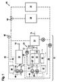
図1および図2において同一の機能または作用形式を備えたエレメントは、同一の符号を備えている。 Elements having the same function or mode of action in FIGS. 1 and 2 have the same reference numerals.
図1には、本発明による熱電併給設備(Kraft-Waerme-Kopplungsanlage:コージェネレーションプラント)10の第1の実施形態が示されている。この熱電併給設備10は、熱を、2つの使用装置、すなわち室暖房の加熱回路50と、建物(図示せず)のための温水システム51とに提供する。熱電併給設備10は、例示的に燃料電池21、すなわちアノード(燃料極)22およびカソード(空気極)23と、アフタバーナ24とを備えた燃料電池設備20を有している。第1の圧縮機27は、アノード22の第1の燃料として天然ガスを流れ経路70に供給する。同様に第2の圧縮機28により、酸素を含んだ空気がカソード23の酸化剤として流れ経路71に供給される。第1および第2の圧縮機27,28は、燃料電池21の手前に配置されている。アノード22において、天然ガス等は水素および一酸化炭素に改質され、水素および一酸化炭素の第1の割合が電気化学的に変換される。この場合に、電流および熱が生成される。変換されなかった水素および一酸化炭素、反応物質としての水および二酸化炭素、ならびに別の改質物質から成る流れは、流れ経路72に向かってアノード22を出て、部分的には再循環流れ経路73でアノード22の入口22’へ、かつ部分的にはアフタバーナ24へ案内される。再循環流れ経路73の圧縮装置29は、どれくらい多くの水素がアノード22へ戻るか、かつどれくらい多くの水素がアフタバーナ24に到達するかを調節することができる。アフタバーナ24内では、水素と、カソード23から流れ経路74に到来する変換されていない酸素とが燃焼される。この場合に、熱が生じる。燃焼物質は、共通の排ガス流75によりアフタバーナ24を出る。水素の第1の割合は、電気需要に応じて生成された熱が熱需要をカバーするか否か、かつどの割合において、電気需要に応じて生成された熱が熱需要をカバーするかによって、最適な割合と、下限値との間で、つまり約50〜80%の間で変化することができる。
FIG. 1 shows a first embodiment of a combined heat and power plant (Kraft-Waerme-Kopplungsanlage: cogeneration plant) 10 according to the present invention. This combined heat and
水素の第1の割合が下限値にある場合に、燃料電池設備によって使用装置50,51に提供される熱が熱需要をカバーしないと、付加的な加熱器30内で第2の燃料としての天然ガスが燃焼される。このためには、第3の圧縮機33によって、天然ガスが流れ経路76で付加的な加熱器30に供給され、かつ空気が第4の圧縮機34によって流れ経路77で付加的な加熱器30に供給される。燃料および空気の流れ経路70,71,72,73,74,75,76,77,78は、実線で示されている。
If the first proportion of hydrogen is at the lower limit and the heat provided to the
燃料電池21により生成された直流電流を交流電流に変換するインバータ41によって、一定の電流、一定の出力または一定の電圧が設定され得る。インバータ41への、かつインバータ41からの電気的な線路は、点線で示されている。消費機を有する電気回路への接続部は図示されていない。
A constant current, a constant output, or a constant voltage can be set by an
熱を授受する熱媒体としての水は、循環路60内を案内される。循環路60に設けられた流路は、破線で示されている。この場合、水はポンプ61によってアフタバーナ24を貫流し、場合によってはポンプ65によって流体技術的に並列に配置された付加加熱器30を貫流して、熱を吸収する。この熱は使用装置50,51内で再び放出される。使用装置50,51は、流体技術的に並列に配置されている。それぞれ使用装置50,51を貫流する水の割合は、3ポート2位置切換弁66によって、調節され得る。燃料電池21自体内で生成された熱は、流れ経路72,74の流れによりアフタバーナ24内に搬送されて、アフタバーナ24から水に伝達される。
Water as a heat medium for transferring heat is guided in the
付加加熱器30と、燃料電池設備20とは、別個の2つの調節装置47,48を有している。両調節装置47,48に、アフタバーナ24と、場合によっては付加加熱器30とを出た水の温度が伝達される。水の温度は、温度測定器46により測定される。この場合、温度測定器46は、付加加熱器30およびアフタバーナ24を通る並列する流路が合流した後の循環路60内に配置されている。燃料電池設備20の調節装置47は、測定された温度に基づいて、第1および第2の圧縮機27,28および圧縮機装置29の電気的な出力を調節する。同様に、調節装置47はインバータ41とも通信している。付加加熱器30の調節装置48は、測定された温度に基づいて第3および第4の圧縮機33,34の電気的な出力を調節する。調節装置47,48の通信経路46は、一点破線で示されている。さらに制御装置および/または調節装置47は、建物の、要求される電気的な出力の測定値を、たとえば同じ建物内で消費することができない電気的な出力を出来るだけ少なくする目的で、制御部および/または調節部に取り入れる。
The
図2には、2つの使用装置50,51を備えた本発明による熱電併給設備10の別の実施形態が示されている。以下に図1との比較における差異についてのみ言及する。
FIG. 2 shows another embodiment of the combined heat and
天然ガスおよび空気は、付加加熱器30内に、共通の排ガス流78内に配置された圧縮機35によって吸い込まれる。この場合、天然ガスと空気との比は、流れ経路76内の弁31と流れ経路77内の弁32とによって調節され得る。同様に、燃料電池設備20内では、排ガス流75内の圧縮機27’によって天然ガスおよび空気の量が調節され、流れ経路70,71内の弁25,26によって、空気に対する天然ガスの比が調節される。再循環は行われない。
Natural gas and air are drawn into the
アフタバーナ24および付加加熱器30は、流体技術的に循環路60内で直列に配置されている。アフタバーナ24の背後に配置された3ポート2位置切換弁64は、燃料電池設備20の熱生成量の高い時間に切り換えられて、これにより水は燃料電池設備20の熱を使用装置50,51ではなく、蓄熱器42に搬送する。このように蓄えられた熱は、熱需要の高い時間にポンプ63によって使用装置50,51に提供され得る。
The
熱電併給設備10は、共通の調節装置40を有している。共通の調節装置40は、外気温を、第1の温度測定器43によって測定し、かつ蓄熱器42の温度を第2および第3の温度測定器44,45によって互いに異なる2つの箇所で測定する。測定された温度は、通信経路46で調節装置40に伝達され、これにより調節装置40は、弁25,26,31,32、圧縮機27’,35およびインバータ41を、本発明による方法に相応して調節するように指示する。同様に、調節装置40が、ポンプ61,63,65を調節することが規定されていてよい(図示せず)。さらに調節装置40は、建物の、要求される電気的な出力の測定値を使用することができる。
The
図3は、電圧Uと、電流Iとの関係のグラフを示している。直線Aは、第1の燃料の低下された第1の割合における電流Iと電圧Uとの関係を示しているのに対して、直線Bは、第1の燃料の高い第1の割合における電流Iと電圧Uとの関係を示している。曲線P(一定)は、一定の電気的な出力Pの線である、低い第1の割合(直線A)では、出力Pが同じままで電流Iが減じられるので、ガス使用率の低下作用の他に、燃料電池21の劣化がさらに減じられ得る。
FIG. 3 shows a graph of the relationship between the voltage U and the current I. Line A shows the relationship between current I and voltage U at a reduced first rate of the first fuel, whereas line B shows the current at a high first rate of the first fuel. The relationship between I and voltage U is shown. The curve P (constant) is a line with a constant electrical output P. At a low first ratio (straight line A), the current I is reduced while the output P remains the same. In addition, the deterioration of the
Claims (10)
第1の燃料の第1の割合を、熱電併給設備(10)に設けられた燃料電池設備(20)の少なくとも1つの燃料電池(21)内で電気化学的に変換し、これによって電気的な出力および熱を生成し、
第1の燃料の、変換されることなしに燃料電池(21)を出る第2の割合を、燃料電池(21)からの進出後に、燃料電池設備(20)のアフタバーナ(24)内で燃焼し、その際に熱を生成し、
熱電併給設備(10)の付加加熱器(30)内で、第2の燃料が燃焼可能であり、その際に熱が生成可能であり、
燃料電池(21)の最適な運転点において、第1の燃料の最適な第1の割合が変換可能である、熱電併給設備(10)を運転する方法において、
燃料電池(21)の最適な運転点において燃料電池設備(20)内で生成可能である熱よりも、熱需要が高い場合に、第1の燃料の第1の割合を、最適な運転点に比べて低下させ、これにより最適な運転点におけるよりも多くの熱をアフタバーナ(24)内で生成することを特徴とする、熱電併給設備を運転する方法。 A method of operating a combined heat and power facility (10),
A first proportion of the first fuel is electrochemically converted in at least one fuel cell (21) of the fuel cell facility (20) provided in the combined heat and power facility (10), thereby being electrically Generate power and heat,
A second proportion of the first fuel leaving the fuel cell (21) without being converted is burned in the afterburner (24) of the fuel cell facility (20) after entering the fuel cell (21). , In that case generate heat,
In the additional heater (30) of the combined heat and power facility (10), the second fuel can be combusted, and heat can be generated at that time.
In a method of operating a combined heat and power plant (10), wherein an optimal first ratio of the first fuel is convertible at an optimal operating point of the fuel cell (21),
When the heat demand is higher than the heat that can be generated in the fuel cell facility (20) at the optimal operating point of the fuel cell (21), the first ratio of the first fuel is set to the optimal operating point. A method of operating a combined heat and power plant, characterized in that it generates a lower heat in the afterburner (24) than at the optimum operating point.
少なくとも1つの燃料電池(21)とアフタバーナ(24)とを備えた燃料電池設備(20)が設けられており、燃料電池(21)内で第1の燃料の第1の割合が電気化学的に変換可能であり、変換されることなしに燃料電池(21)を出た、第1の燃料の第2の割合が、アフタバーナ(24)内で燃料可能であり、
さらに付加加熱器(30)が設けられており、該付加加熱器(30)内で第2の燃料が燃焼可能である形式の熱電併給設備において、
熱電併給設備(10)が、少なくとも1つの制御部および/または調節部(40,47,48)を有していて、該制御部および/または調節部(40,47,48)が、燃料電池(21)の最適な運転点において燃料電池設備(20)によって生成可能である熱よりも高い熱需要がある場合に、第1の燃料の第1の割合を低下させることで、燃料電池の最適な運転点におけるよりも多くの第1の燃料が、アフタバーナ(24)内で燃焼されることを特徴とする、熱電併給設備。 A combined heat and power facility (10),
A fuel cell facility (20) comprising at least one fuel cell (21) and an afterburner (24) is provided, wherein the first proportion of the first fuel is electrochemically contained in the fuel cell (21). A second proportion of the first fuel that is convertible and exits the fuel cell (21) without being converted is fuelable in the afterburner (24);
Further, in the combined heat and power facility of the type in which an additional heater (30) is provided and the second fuel can be combusted in the additional heater (30),
The cogeneration facility (10) has at least one control unit and / or adjustment unit (40, 47, 48), and the control unit and / or adjustment unit (40, 47, 48) is a fuel cell. When there is a higher heat demand than the heat that can be generated by the fuel cell facility (20) at the optimal operating point of (21), the first rate of the first fuel is reduced to optimize the fuel cell. Combined heat and power installation, characterized in that more first fuel is burned in the afterburner (24) than at the point of operation.
Applications Claiming Priority (3)
| Application Number | Priority Date | Filing Date | Title |
|---|---|---|---|
| DE102010001011.1 | 2010-01-19 | ||
| DE102010001011A DE102010001011A1 (en) | 2010-01-19 | 2010-01-19 | Method for operating a combined heat and power plant |
| PCT/EP2011/050502 WO2011089082A2 (en) | 2010-01-19 | 2011-01-17 | Method for operating a cogeneration plant |
Publications (2)
| Publication Number | Publication Date |
|---|---|
| JP2013527555A true JP2013527555A (en) | 2013-06-27 |
| JP2013527555A5 JP2013527555A5 (en) | 2013-08-08 |
Family
ID=44307312
Family Applications (1)
| Application Number | Title | Priority Date | Filing Date |
|---|---|---|---|
| JP2012549316A Pending JP2013527555A (en) | 2010-01-19 | 2011-01-17 | How to operate a cogeneration facility |
Country Status (4)
| Country | Link |
|---|---|
| EP (1) | EP2526344B1 (en) |
| JP (1) | JP2013527555A (en) |
| DE (1) | DE102010001011A1 (en) |
| WO (1) | WO2011089082A2 (en) |
Families Citing this family (6)
| Publication number | Priority date | Publication date | Assignee | Title |
|---|---|---|---|---|
| DE102012221461A1 (en) | 2011-11-30 | 2013-06-06 | Robert Bosch Gmbh | Fuel cell system and method for operating a fuel cell system |
| DE102013204162A1 (en) | 2013-03-11 | 2014-09-11 | Robert Bosch Gmbh | Heating system and method for operating a heating system |
| DE102013207349A1 (en) | 2013-04-23 | 2014-10-23 | Robert Bosch Gmbh | Cogeneration plant |
| DE102014204789A1 (en) | 2014-03-14 | 2015-09-17 | Volkswagen Aktiengesellschaft | Energy management method for a vehicle and energy management device |
| DE102014226031A1 (en) | 2014-12-16 | 2016-06-16 | Volkswagen Aktiengesellschaft | Method and device for predicting a range of a vehicle with at least partially electric drive |
| AT521209B1 (en) * | 2018-05-03 | 2020-11-15 | Avl List Gmbh | Fuel cell system, stationary power plant and method for operating a fuel cell system |
Citations (12)
| Publication number | Priority date | Publication date | Assignee | Title |
|---|---|---|---|---|
| JPH07169474A (en) * | 1993-12-15 | 1995-07-04 | Toshiba Corp | Methanol switching type fuel cell system |
| JP2001185196A (en) * | 1999-12-28 | 2001-07-06 | Daikin Ind Ltd | Fuel cell system |
| JP2001185167A (en) * | 1999-12-27 | 2001-07-06 | Daikin Ind Ltd | Fuel cell cogeneration system |
| JP2002050377A (en) * | 2000-08-01 | 2002-02-15 | Matsushita Electric Ind Co Ltd | Fuel cell system |
| JP2004150646A (en) * | 2002-10-28 | 2004-05-27 | Sekisui Chem Co Ltd | Cogeneration system |
| JP2004164868A (en) * | 2002-11-08 | 2004-06-10 | Sanyo Electric Co Ltd | Hot water storage method in co-generation system, and its device |
| JP2004178962A (en) * | 2002-11-27 | 2004-06-24 | Hitachi Ltd | Fuel cell power generating system using hydrogen manufacturing device having combustor |
| JP2006073316A (en) * | 2004-09-01 | 2006-03-16 | Tokyo Gas Co Ltd | Fuel cell cogeneration system and its control method |
| JP2007305429A (en) * | 2006-05-11 | 2007-11-22 | Matsushita Electric Ind Co Ltd | Fuel cell system |
| JP2007309598A (en) * | 2006-05-19 | 2007-11-29 | Matsushita Electric Ind Co Ltd | Cogeneration system |
| JP2009205932A (en) * | 2008-02-27 | 2009-09-10 | Mitsubishi Heavy Ind Ltd | Combined system |
| JP2009289540A (en) * | 2008-05-28 | 2009-12-10 | Nissan Motor Co Ltd | Fuel battery system, and operation method thereof |
Family Cites Families (7)
| Publication number | Priority date | Publication date | Assignee | Title |
|---|---|---|---|---|
| EP0818840B1 (en) * | 1996-07-11 | 2002-04-03 | Sulzer Hexis AG | Process for generating simultaneously electrical energy and heat for heating purposes |
| AT410862B (en) | 2001-12-17 | 2003-08-25 | Vaillant Gmbh | METHOD FOR OPTIMIZING THE OPERATION OF A PLANT FOR THE SIMULTANEOUS GENERATION OF ELECTRICAL AND THERMAL ENERGY WITH A FUEL CELL HEATER |
| AT411943B (en) * | 2002-05-06 | 2004-07-26 | Vaillant Gmbh | METHOD FOR OPERATING A FUEL CELL SYSTEM |
| AT503130B1 (en) * | 2006-03-15 | 2007-08-15 | Vaillant Austria Gmbh | COMBINATION OF A HEATER WITH A FUEL CELL SYSTEM AND A METHOD FOR OPERATING THIS COMBINATION |
| DE102007019359A1 (en) * | 2007-04-23 | 2008-10-30 | J. Eberspächer GmbH & Co. KG | Fuel cell system and associated starting method |
| JP5164657B2 (en) * | 2008-04-25 | 2013-03-21 | アイシン精機株式会社 | Fuel cell system |
| DE102008037028B4 (en) * | 2008-08-08 | 2011-05-26 | Köhne, Stephan, Dr. | Fuel cell system for gaseous hydrocarbons and associated operating method |
-
2010
- 2010-01-19 DE DE102010001011A patent/DE102010001011A1/en not_active Withdrawn
-
2011
- 2011-01-17 JP JP2012549316A patent/JP2013527555A/en active Pending
- 2011-01-17 EP EP11700747.6A patent/EP2526344B1/en active Active
- 2011-01-17 WO PCT/EP2011/050502 patent/WO2011089082A2/en active Application Filing
Patent Citations (12)
| Publication number | Priority date | Publication date | Assignee | Title |
|---|---|---|---|---|
| JPH07169474A (en) * | 1993-12-15 | 1995-07-04 | Toshiba Corp | Methanol switching type fuel cell system |
| JP2001185167A (en) * | 1999-12-27 | 2001-07-06 | Daikin Ind Ltd | Fuel cell cogeneration system |
| JP2001185196A (en) * | 1999-12-28 | 2001-07-06 | Daikin Ind Ltd | Fuel cell system |
| JP2002050377A (en) * | 2000-08-01 | 2002-02-15 | Matsushita Electric Ind Co Ltd | Fuel cell system |
| JP2004150646A (en) * | 2002-10-28 | 2004-05-27 | Sekisui Chem Co Ltd | Cogeneration system |
| JP2004164868A (en) * | 2002-11-08 | 2004-06-10 | Sanyo Electric Co Ltd | Hot water storage method in co-generation system, and its device |
| JP2004178962A (en) * | 2002-11-27 | 2004-06-24 | Hitachi Ltd | Fuel cell power generating system using hydrogen manufacturing device having combustor |
| JP2006073316A (en) * | 2004-09-01 | 2006-03-16 | Tokyo Gas Co Ltd | Fuel cell cogeneration system and its control method |
| JP2007305429A (en) * | 2006-05-11 | 2007-11-22 | Matsushita Electric Ind Co Ltd | Fuel cell system |
| JP2007309598A (en) * | 2006-05-19 | 2007-11-29 | Matsushita Electric Ind Co Ltd | Cogeneration system |
| JP2009205932A (en) * | 2008-02-27 | 2009-09-10 | Mitsubishi Heavy Ind Ltd | Combined system |
| JP2009289540A (en) * | 2008-05-28 | 2009-12-10 | Nissan Motor Co Ltd | Fuel battery system, and operation method thereof |
Also Published As
| Publication number | Publication date |
|---|---|
| DE102010001011A1 (en) | 2011-07-21 |
| EP2526344A2 (en) | 2012-11-28 |
| EP2526344B1 (en) | 2016-04-06 |
| WO2011089082A2 (en) | 2011-07-28 |
| WO2011089082A3 (en) | 2013-05-30 |
Similar Documents
| Publication | Publication Date | Title |
|---|---|---|
| JP5331819B2 (en) | MCFC power generation system | |
| US10938046B2 (en) | Fuel cell system | |
| JP5763405B2 (en) | Fuel cell system | |
| US10381665B2 (en) | Device and method for heating fuel cell stack and fuel cell system having the device | |
| JP2013527555A (en) | How to operate a cogeneration facility | |
| US8092953B2 (en) | Fuel cell system and method of operating the fuel cell system | |
| JP2009277621A (en) | Fuel-cell system | |
| EP2164126B1 (en) | Fuel Cell System and Fuel Supply Method thereof | |
| JP6113480B2 (en) | Fuel cell and operation method thereof | |
| US8642221B2 (en) | Solid oxide fuel cell device | |
| WO2008016257A1 (en) | Fuel cell system and operating method | |
| JP5391976B2 (en) | Solid oxide fuel cell | |
| JP2009081052A (en) | Solid oxide fuel cell power generation system and operation control method of solid oxide fuel cell power generation system | |
| JP2011076941A (en) | Solid oxide fuel cell | |
| KR20180000447A (en) | Fuel cell system with heat exchager using reformed gas or anode off gas | |
| JP4342172B2 (en) | Co-energy system | |
| US20200266460A1 (en) | Fuel cell system and fuel cell system control method | |
| JP2013157189A (en) | Energy management device | |
| JP5646223B2 (en) | Fuel cell power generation system and operation method thereof | |
| JP2001283882A (en) | Generating device utilizing fuel cell | |
| JP2001015134A (en) | Combined power generating device of fuel cell with gas turbine | |
| JP3897149B2 (en) | Solid oxide fuel cell and Stirling engine combined system | |
| JP2011076942A (en) | Solid oxide fuel cell | |
| JP3939333B2 (en) | Hot water system | |
| CA2601226A1 (en) | Reformer, method for controlling pump in fuel cell system, and control unit |
Legal Events
| Date | Code | Title | Description |
|---|---|---|---|
| A977 | Report on retrieval |
Free format text: JAPANESE INTERMEDIATE CODE: A971007 Effective date: 20131030 |
|
| A601 | Written request for extension of time |
Free format text: JAPANESE INTERMEDIATE CODE: A601 Effective date: 20140205 |
|
| A602 | Written permission of extension of time |
Free format text: JAPANESE INTERMEDIATE CODE: A602 Effective date: 20140213 |
|
| A521 | Request for written amendment filed |
Free format text: JAPANESE INTERMEDIATE CODE: A523 Effective date: 20140507 |
|
| A02 | Decision of refusal |
Free format text: JAPANESE INTERMEDIATE CODE: A02 Effective date: 20140707 |