JP4940835B2 - Game machine - Google Patents

Game machine Download PDF

Info

Publication number
JP4940835B2
JP4940835B2 JP2006237030A JP2006237030A JP4940835B2 JP 4940835 B2 JP4940835 B2 JP 4940835B2 JP 2006237030 A JP2006237030 A JP 2006237030A JP 2006237030 A JP2006237030 A JP 2006237030A JP 4940835 B2 JP4940835 B2 JP 4940835B2
Authority
JP
Japan
Prior art keywords
opening
closing
ball
game
closing member
Prior art date
Legal status (The legal status is an assumption and is not a legal conclusion. Google has not performed a legal analysis and makes no representation as to the accuracy of the status listed.)
Expired - Fee Related
Application number
JP2006237030A
Other languages
Japanese (ja)
Other versions
JP2008055006A5 (en
JP2008055006A (en
Inventor
良典 大野
Current Assignee (The listed assignees may be inaccurate. Google has not performed a legal analysis and makes no representation or warranty as to the accuracy of the list.)
Sanyo Bussan Co Ltd
Original Assignee
Sanyo Bussan Co Ltd
Priority date (The priority date is an assumption and is not a legal conclusion. Google has not performed a legal analysis and makes no representation as to the accuracy of the date listed.)
Filing date
Publication date
Application filed by Sanyo Bussan Co Ltd filed Critical Sanyo Bussan Co Ltd
Priority to JP2006237030A priority Critical patent/JP4940835B2/en
Publication of JP2008055006A publication Critical patent/JP2008055006A/en
Publication of JP2008055006A5 publication Critical patent/JP2008055006A5/ja
Application granted granted Critical
Publication of JP4940835B2 publication Critical patent/JP4940835B2/en
Expired - Fee Related legal-status Critical Current
Anticipated expiration legal-status Critical

Links

Images

Description

本発明は、パチンコ機等に代表される遊技機に関するものである。   The present invention relates to a gaming machine represented by a pachinko machine or the like.

従来、例えば、遊技の制御を行う主制御装置と、その主制御装置で行われる遊技の制御に伴った表示を、液晶画面を有する表示装置で行わせる表示制御装置とを備えたパチンコ機が知られている。このパチンコ機では、液晶画面で複数の図柄列が動的表示され、その図柄列を構成する図柄が所定の組合わせで停止表示された場合に、遊技者に有利な遊技価値を付与する大当たりが発生する。   Conventionally, for example, a pachinko machine having a main control device that controls a game and a display control device that displays a display associated with the game control performed by the main control device on a display device having a liquid crystal screen is known. It has been. In this pachinko machine, when a plurality of symbol rows are dynamically displayed on the liquid crystal screen and the symbols constituting the symbol rows are stopped and displayed in a predetermined combination, the jackpot that gives the player a game value advantageous to the player is obtained. Occur.

この大当たりが発生すると、特定の入に付随する1枚扉が所定回数開閉動作して、多くの賞球が払い出される。1枚扉の開閉動作は、下端が回転軸となり、上端が遊技領域側(特定の入とは反対側)に回動して行われる。また、1枚扉と特定の入との間には、球を収容する収容空間が設けられており、1枚扉が開姿勢となると、その1枚扉により遊技領域を流下する球が受け止められ、収容空間内に球が流入する。収容空間に流入された球は、特定の入方向へ誘導され、特定の入に入した球の通過が球検出センサにより検出されると、賞球が払い出される。1枚扉は、開姿勢の状態で所定数(例えば10個)の球の通過が球検出センサにより検出されると閉姿勢となり(1枚扉の1回の開閉動作で1ラウンド)、この1枚扉の開閉動作が所定回数(例えば16ラウンド)行われると、大当たりが終了する。 When this jackpot occurs, the one door associated with a particular entry mouth operated a predetermined number of times opening and closing a number of prize balls are paid out. Opening and closing of the one door, the lower end as a rotary shaft is performed by rotating (the opposite side to the specific input mouth) upper end game area side. Between the one door with a particular input mouth, spheres and housing space are provided housing a, the one door is opened attitude, receiving spheres flowing down the game area by its one door The sphere flows into the accommodation space. Flowed into the housing space sphere is guided to a specific entry mouth direction, when the passage of a sphere and enter the sphere to particular input mouth is detected by the ball detection sensor, prize balls are paid out. The single door is in a closed posture when a predetermined number (for example, ten) of spheres are detected by the ball detection sensor in an open posture (one round of one door opening / closing operation). The jackpot ends when the opening / closing operation of the single door is performed a predetermined number of times (for example, 16 rounds).

上述したパチンコ機は、1枚扉は下端を回転軸として上端が遊技領域側に回動して開姿勢となるので、1枚扉が閉姿勢に回動する際には、その1枚扉と収容空間の遊技領域側の開口との間で、収容空間に流入する球を挟んでしまうこともある。1枚扉と収容空間の開口との間に球が挟まると、1枚扉が閉姿勢に回動したにも関わらず、収容空間の開口が閉鎖されないので、必要以上の球が入してしまうことがあった。 In the pachinko machine described above, the single door has the lower end as the rotation axis and the upper end rotates to the game area side to the open position. A ball flowing into the accommodation space may be sandwiched between the opening of the accommodation space on the game area side. When ball between the opening of one door and the housing space sandwiched, despite the one door is rotated to the closed position, the opening of the accommodation space is not closed, excessive sphere by entering sphere There was a case.

また、1枚扉が遊技領域側に回動して所定数の球の通過が球検出センサにより検出されると、1枚扉が開姿勢から閉姿勢に回動するが、所定数の最後の球(例えば10個目の球)が球検出センサにより検出されるとき、既に収容空間内に球が収容されていることがある。そのため、1枚扉の1回の開閉動作で必要以上の球が入してしまうことがあった。 Further, when one door is rotated to the game area side and the passage of a predetermined number of balls is detected by the ball detection sensor, the single door is rotated from the open position to the closed position. When a sphere (for example, the tenth sphere) is detected by the sphere detection sensor, the sphere may already be accommodated in the accommodation space. Therefore, there may need more spheres in a single opening and closing operation of one door will be entering sphere.

さらに、1枚扉が閉姿勢に回動するタイミングで流下する球を受け止めると、その衝突の力が1枚扉を開姿勢にする方向に作用するので、1枚扉が閉姿勢となるまでの時間が長引くこともある。よって、1枚扉の開姿勢の状態が長くなるので、1枚扉に衝突した最後の球を収容空間に誘導するだけでなく、さらに球が収容空間に収容され易くなってしまい、必要以上の球が入してしまうことがあった。 Furthermore, if the ball that flows down at the timing when the single door is turned to the closed position is received, the force of the collision acts in a direction to open the single door, so that the single door is in the closed position. Time may be prolonged. Therefore, since the state of the open posture of the single door becomes long, not only the last ball colliding with the single door is guided to the storage space, but also the ball becomes easy to be stored in the storage space. It was sometimes result in TamagaIri ball.

一般的に、パチンコ機は、遊技領域に打ち込まれた発射数および遊技者に払い出される賞球数などの各条件に基づいて予め大当たりの抽選確率などの仕様が設定されているので、賞球の払出数が最も多くなる大当たり時の賞球数にばらつきが大きいと、抽選確率を設定する際に参照された条件と、実際に遊技された場合の条件とが異なってしまう。よって、1枚扉を付随した入に入する球数にばらつきが大きいと、予め定めた仕様とは異なる意図しない仕様のパチンコ機となり易いという問題点があった。 In general, pachinko machines are pre-set with specifications such as the probability of winning a lottery based on conditions such as the number of shots struck into the game area and the number of prize balls to be paid out to the player. If there is a large variation in the number of winning balls when the number of payouts is the largest, the conditions referred to when the lottery probability is set differ from the conditions when the game is actually played. Therefore, the variation in the sphere number of entering sphere inlet mouth which accompanied the one door is large, there is a problem that tends pachinko machine different unintended specifications with a predetermined specification.

本発明は、上記例示した問題点を解決するためになされたものであり、扉式の入に入する遊技球数のばらつきを抑えることができる遊技機を提供することを目的としている。 The present invention has been made to solve the above SL illustrated or problem, in order to provide a gaming machine capable of suppressing variation in the game balls number of entering sphere inlet mouth of the door type Yes.

この目的を達成するために請求項1記載の遊技機は、遊技球が流下する遊技領域と、その遊技領域を流下する遊技球が入する入と、その入へ入した遊技球の通過を検出する通過検出手段とを備え、その通過検出手段により前記入を通過する遊技球が検出されると、所定の遊技価値が付与されるものであり、前記入と遊技領域との間に所定空間を有して形成され、前記遊技領域から流入した遊技球を収容する収容部と、その収容部の前記遊技領域側の開口を開閉すると共に、前記収容部の前記開口を閉鎖する閉姿勢において前記遊技球の流下方向の上流側で且つ前記収容部の前記開口を開放する開姿勢において前記収容部の所定空間内に位置する開閉上流部と、その開閉上流部より前記閉姿勢において前記流下方向の下流側に位置する開閉下流部とを有し、前記開姿勢となると、前記開閉上流部が前記収容部の所定空間内に位置すると共に前記開閉下流部が前記遊技領域に突出し、前記閉姿勢となると、前記開閉上流部および開閉下流部の前記入へ遊技球を案内する案内面が前記遊技領域側に位置する開閉部材と、その開閉部材を回転可能に支持する回転軸と、その回転軸を中心として前記開閉部材を第1方向に駆動させて前記開姿勢にすると共に、前記回転軸を中心として前記開閉部材を反第1方向に駆動させて前記閉姿勢にする駆動手段と、その駆動手段の駆動制御を行う駆動制御手段とを備え、その駆動制御手段は、前記開閉部材が前記反第1方向に駆動する場合に、その駆動速度または駆動方向の少なくとも一方を変化させる速度制御手段を備えている。 Gaming machine of claim 1, wherein in order to achieve the object, a game area where the game ball is flowing down, the inlet mouth game ball enters or sphere flowing down the game area, the game ball with Type spheres to the entrance mouth and a passage detection means for detecting the passage of the game ball is detected to pass through the entering-port by the passage detection means, which predetermined game value is given, the entering-port and game area And a storage portion that holds a game ball that has flowed in from the game area, and opens and closes the opening on the game area side of the storage portion, and closes the opening of the storage portion. An opening / closing upstream portion located in a predetermined space of the housing portion in an open posture in which the opening of the housing portion is opened upstream of the gaming ball in the flow-down direction and the opening posture of the housing portion. At the downstream side in the flow direction The opening / closing downstream portion is located in a predetermined space of the housing portion, the opening / closing downstream portion protrudes into the game area, and the opening / closing downstream portion protrudes into the game area. an upstream portion and closing member guide surface for guiding the game balls to the entering opening of the opening and closing the downstream portion is positioned on the game area side, a rotary shaft which rotatably supports the opening and closing member, said about its rotation axis Driving means for driving the opening / closing member in the first direction to the open position, driving the opening / closing member in the anti-first direction about the rotation shaft to make the closing position, and drive control of the driving means Drive control means for performing the control, and the drive control means includes speed control means for changing at least one of the drive speed and the drive direction when the opening / closing member is driven in the anti-first direction.

なお、速度制御手段により変化される駆動速度は、所定の速度より単に遅い駆動速度だけでなく、駆動速度が0となり停止する場合も含まれる。   Note that the drive speed changed by the speed control means includes not only a drive speed that is slower than a predetermined speed but also a case where the drive speed becomes 0 and stops.

請求項2記載の遊技機は、請求項1記載の遊技機において、前記速度制御手段は、前記開閉部材が前記反第1方向に駆動する場合に、前記入に遊技球が案内される傾斜位置から前記入に遊技球が案内されない傾斜位置まで前記開閉部材が駆動した後、その開閉部材の駆動を少なくとも1回以上停止させるものである。 Gaming machine of claim 2, in claim 1 gaming machine, wherein said speed control means, when the closing member is driven in the counterclockwise first direction, the game ball before filling opening is inclined guide after the game ball from a position before entry port has driven the opening and closing member to the inclined position not guided, the driving of the opening and closing member is intended to stop at least once.

請求項3記載の遊技機は、請求項1又は2に記載の遊技機において、前記速度制御手段は、前記開閉部材が前記反第1方向に駆動する間に、その開閉部材の前記第1方向への駆動を少なくとも1回以上行わせるものであり、その開閉部材の第1方向へ駆動される距離は、前記開閉部材が前記開姿勢から前記反第1方向に駆動した距離より短い。   The gaming machine according to claim 3 is the gaming machine according to claim 1 or 2, wherein the speed control means is configured to move the opening / closing member in the first direction while the opening / closing member is driven in the anti-first direction. Is driven at least once, and the distance that the opening / closing member is driven in the first direction is shorter than the distance that the opening / closing member is driven in the anti-first direction from the open posture.

請求項4記載の遊技機は、請求項1から3のいずれかに記載の遊技機において、前記速度制御手段により前記開閉部材の駆動速度または駆動方向の少なくとも一方が変化させられる範囲は、前記開姿勢から閉姿勢への全範囲より短い範囲で構成されている。   The gaming machine according to claim 4 is the gaming machine according to any one of claims 1 to 3, wherein a range in which at least one of a driving speed or a driving direction of the opening / closing member is changed by the speed control means is the opening degree. The range is shorter than the entire range from the posture to the closed posture.

請求項1記載の遊技機によれば、遊技領域に打ち込まれた遊技球が入に入し、その入した遊技球が通過検出手段により検出されると、所定の遊技価値が付与される。収容部の開口は、開閉部材により開閉され、その開閉部材は、駆動制御手段によって駆動手段が制御され回転軸が第1方向に駆動されると開姿勢となり、駆動手段が制御され回転軸が反第1方向に駆動されると閉姿勢となる。また、開閉部材は、開閉上流部と開閉下流部とを有しており、開姿勢となると、開閉上流部が収容部の所定空間内に位置すると共に開閉下流が遊技領域に位置するので、開閉部材が開姿勢となった場合には、遊技領域を流下する遊技球が開閉下流部により受け止められ、その受け止められた遊技球が開閉上流部を通り入へ案内され入がなされる。また、開閉部材が閉姿勢となると、開閉上流部および開閉下流部の案内面が遊技領域側に位置するので、開姿勢から閉姿勢に回動する際に開閉上流部を通過している未入の遊技球を収容部から遊技領域に排出することができる。従って、必要な遊技球の通過が検出手段により検出された場合に開閉部材を閉姿勢へ回動させることで、必要以上の遊技球が入に入することを抑制することができる。さらに、開閉部材が反第1方向に駆動する場合には、速度制御手段により制御され、開閉部材が第1方向に駆動する場合の駆動速度または駆動方向の少なくとも一方を変化させることができる。ここで、例えば、開閉部材が反第1方向に駆動する駆動速度が所定速度より速い場合には、その反第1方向へ駆動する際に遊技球が跳ねたりばたつくことが考えられ、その遊技球がばたつくことによって開閉上流部と収容部の開口との間に遊技球を挟んでしまうことがある。開閉上流部と収容部の開口との間に遊技球を挟んでしまうと、開閉部材が閉姿勢の位置まで回動できず収容部の開口が開放されたままの状態となり、必要以上の遊技球が収容部に流入して必要以上の遊技球が入に入し易くなってしまう。しかし、本遊技機によれば、開閉部材を反第1方向に駆動する駆動速度を遅くもできるので、遊技球の跳ねやばたつきを抑制でき収容部内にある未入の遊技球を遊技領域にスムーズに排出できるし、開閉部材を一旦第1方向に駆動させることで、収容部の開口と開閉部材との間で遊技球を挟むことを抑制することができる。よって、収容部の開口が開放されたままの状態となることを抑制できるので、必要以上の球が入に入することを抑制することができるという効果がある。 According to claim 1 the gaming machine described in the game balls implanted into the game area Type sphere inlet mouth, the game balls that the incoming ball is detected by the passage detection means, a predetermined game value is given The The opening of the housing portion is opened and closed by an opening and closing member, and the opening and closing member is in an open position when the driving means is controlled by the drive control means and the rotating shaft is driven in the first direction, and the driving means is controlled and the rotating shaft is counteracted. When driven in the first direction, a closed posture is assumed. The opening / closing member has an opening / closing upstream portion and an opening / closing downstream portion. When the opening / closing member is in the open position, the opening / closing upstream portion is located in a predetermined space of the housing portion and the opening / closing downstream portion is located in the game area. member when in the open position, the game ball flowing down the game region is received by the opening and closing the downstream portion, the received was game ball is guided off upstream portion and into the entrance mouth entrance sphere is made. When the opening / closing member is in the closed position, the guide surfaces of the opening / closing upstream part and the opening / closing downstream part are located on the game area side. it can be discharged to the game region sphere of game ball from the accommodation unit. Therefore, the opening and closing member when the passing of the necessary game ball is detected by the detecting means by rotating the closed position, it is possible to suppress the excessive game ball enters or sphere inlet mouth. Further, when the opening / closing member is driven in the anti-first direction, it is controlled by the speed control means, and at least one of the driving speed and the driving direction when the opening / closing member is driven in the first direction can be changed. Here, for example, when the driving speed at which the opening / closing member is driven in the anti-first direction is higher than a predetermined speed, it is considered that the game ball jumps or flutters when driven in the anti-first direction. The game ball may be pinched between the opening / closing upstream portion and the opening of the housing portion due to fluttering. If a game ball is sandwiched between the opening / closing upstream portion and the opening of the housing portion, the opening / closing member cannot be rotated to the closed position, and the opening of the housing portion remains open, so that more than necessary game balls There undue game ball and flows into the accommodating portion becomes liable to enter sphere inlet mouth. However, according to this game machine, the closing member since the driving speed to drive in a counter first direction slower also, the game region game balls non inlet ball located in housing portion can be suppressed splashing or flapping game balls It is possible to smoothly discharge, and once the opening / closing member is driven in the first direction, it is possible to prevent the game ball from being sandwiched between the opening of the housing portion and the opening / closing member. Therefore, since the opening of the accommodating portion can be prevented from becoming a state of being open, there is an effect that it is possible to prevent the excessive spheres enters or sphere inlet mouth.

また、開閉部材が反第1方向へ駆動して、開閉部材が収容部から遊技領域方向に下降傾斜する位置となると、収容部内の遊技球は遊技領域に排出されると共に開閉下流部に受け止められた遊技球は収容部内に流入することなく遊技領域を流下する。よって、開閉部材が反第1方向へ駆動される際に、収容部に流入する遊技球数が減少するので、開閉上流部と収容部の開口との間に遊技球が挟まれることを抑制することができるという効果がある。よって、開閉部材の位置が入に遊技球案内る傾斜位置までは開閉部材を速く駆動させ、入に遊技球案内ない傾斜位置からは開閉部材の駆動を遅くすることが好ましい。これは、入へ必要以上の球が入することをより低減できるし、遊技球のばたつきも抑制できるので収容部の開口と開閉部材との間で遊技球を挟むことを抑制きるからである。 Further, when the opening / closing member is driven in the anti-first direction and the opening / closing member reaches a position where the opening / closing member is inclined downward in the direction of the game area, the game ball in the storage part is discharged to the game area and received by the opening / closing downstream part. The game balls that have flown down the game area without flowing into the housing portion. Therefore, when the opening / closing member is driven in the anti-first direction, the number of game balls flowing into the housing portion is reduced, so that the game balls are prevented from being sandwiched between the opening / closing upstream portion and the opening of the housing portion. There is an effect that can be. Therefore, the position of the opening and closing member entering the mouth to the inclined position you guide the game ball fast so driving the opening and closing member, it is preferable to slow down the drive of the closing member from the inclined position not guide the game ball to enter the mouth . This is to require more spheres to enter the mouth can be further reduced to enter the sphere, the fluttering of the game balls can be suppressed, cut with suppressed sandwiching the game ball with the opening of the housing portion and the closing member Because.

また、遊技領域に打ち込まれる遊技球数に対して付与される遊技価値が予め定められている場合には、1回の開閉部材の開閉動作で入する遊技球数にばらつきがあると、予め定めた遊技機の仕様とは異なる意図しない仕様の遊技機となってしまう。しかし、本遊技機によれば、1回の開閉動作で必要以上の遊技球が入に入することを抑制できるので、入する遊技球数のばらつきを少なくでき、予め定めた遊技機の仕様に対して極端に異なる仕様の遊技機となることを低減することができるという効果がある。 Also, when the game value is given to the game ball number, which are discharged to the game region is predetermined, if there is a variation in the number of gaming balls to enter sphere opening and closing operation of one of the closing member, in advance The gaming machine has an unintended specification that is different from the determined gaming machine specification. However, according to the gaming machine, it is possible to suppress the one opening and closing operation at excessive gaming ball enters or sphere inlet mouth, can reduce the variation in the game balls number of incoming spheres, predetermined game machine There is an effect that it is possible to reduce the gaming machine having specifications that are extremely different from the specifications.

また、開閉上流部および開閉下流部は、遊技球を入に案内する案内面となるので、その案内面に汚れなどが付着していると遊技球がスムーズな動作ができずに、入に時間がかかったり遊技球が詰まってしまう場合があるが、開閉部材が閉姿勢となると、開閉上流部および開閉下流部の案内面が遊技領域側に位置するので、汚れを発見した場合に簡単に除去が行える。よって、通路の汚れなどによって遊技球がスムーズに流れずに入までに時間がかかったり遊技球が詰まったりすることを低減することができるという効果がある。また、例えば、遊技球が汚れなどにより開閉上流部または開閉下流部の案内面に付着してしまった場合には、遊技者が遊技を続行することで付着した遊技球と流下する遊技球が接触して、その付着した遊技球を自然に落下させることができる。よって、付着した遊技球を取り除くために遊技を中断する回数が少なくなるので、遊技者に不快感を与えることを低減する遊技機を提供することができるという効果がある。 Also, closing the upstream portion and open downstream portion, since a guide surface for guiding the game balls to enter the mouth, unable the dirt on the guide surface is attached gaming ball is smooth operation, incoming balls However, if the opening / closing member is in the closed position, the opening / closing upstream and opening / closing downstream guide surfaces are located on the gaming area side, so it is easy to detect dirt. Can be removed. Therefore, there is an effect that it is possible to reduce the game ball by dirt passage is time to enter the sphere rests or game balls clogged without flowing smoothly. In addition, for example, when a game ball adheres to the guide surface of the upstream / downstream opening / closing downstream portion due to dirt or the like, the game ball that has flowed down and the game ball that has flowed down come into contact with the player as the game continues. Then, the attached game ball can be dropped naturally. Therefore, since the number of times the game is interrupted to remove the attached game ball is reduced, it is possible to provide a gaming machine that can reduce discomfort to the player.

また、開閉部材は、開姿勢の状態で遊技球を開閉下流部で受け止めるているので、遊技球が開閉下流部に衝突して生じる力は、開閉下流部が閉姿勢に回動する方向に作用する。従って、遊技球を受ける際に作用する力によって開閉部材の閉姿勢への回動の妨げとなることがないのでスムーズな閉動作が行え、必要以上の遊技球が入に入することを抑制することができるという効果がある。 In addition, since the open / close member receives the game ball at the open / close downstream portion in the open posture, the force generated when the game ball collides with the open / close downstream portion acts in the direction in which the open / close downstream portion rotates to the closed posture. To do. Therefore, since there can be hindered from rotating in the closed position of the closing member by a force acting upon receiving the game balls can be done smoothly closing, that excessive game ball enters or sphere inlet mouth There is an effect that it can be suppressed.

ここで、従来の一枚扉のように、下端が回転軸となり上端が遊技領域側に回動する場合には、例えば、遊技領域の下方から板状部材(又は線状部材)などを侵入させ、一枚扉の上端に板状部材を引っ掛けて強制的に回動させて、必要以上の遊技球を入口にさせる行為が行われることも考えられる。しかし、本遊技機によれば、開閉部材の上端に板状部材を引っ掛けて回動させようとした場合には、開閉下流部が遊技領域側に突出するように回動するので、板状部材の引っかかりを解除したり切断することができ、強制的に開閉部材を回動させる行為を困難にすることができる。よって、開閉部材が強制的に回動させられて必要以上の球が入に入させられる行為を低減することができるという効果がある。 Here, when the lower end is a rotation axis and the upper end is rotated to the game area side as in a conventional single door, for example, a plate-like member (or a linear member) or the like is inserted from below the game area. , by forcibly rotated by hooking the plate member to the upper end of one door, the act of entering a sphere requires more game balls to the inlet also conceivable to take place. However, according to this gaming machine, when the plate-like member is hooked on the upper end of the opening / closing member to rotate, the opening / closing downstream portion rotates so as to protrude toward the game area side. Can be released or cut, and the act of forcibly rotating the opening / closing member can be made difficult. Therefore, there is an effect that the opening and closing member can be forcibly required more spheres are rotated to reduce the action provoking entering sphere inlet mouth.

請求項2記載の遊技機によれば、請求項1記載の遊技機の奏する効果に加え、開閉部材が反第1方向に駆動する場合には、入に遊技球が案内される傾斜位置から遊技球が案内されない傾斜位置に開閉部材が駆動した後に、速度制御手段によって、開閉部材の駆動が少なくとも1回以上停止させられるので、その開閉部材が停止させられる際に遊技球が前側に移動し、開閉部材が閉姿勢へ回転駆動する際に開閉部材と収容部の開口との間に遊技球を挟んでしまうことを抑制できる。よって、収容部の開口が開放されたままの状態となることを抑制でき、必要以上の球が入に入することを抑制することができるという効果がある。 According to claim 2 gaming machine described, in addition to the effects of the gaming machine according to claim 1, wherein, when the closing member is driven in a counter first direction, from the inclined position where game balls are guided to enter the mouth After the opening / closing member is driven to an inclined position where the game ball is not guided, the driving of the opening / closing member is stopped at least once by the speed control means. Therefore, when the opening / closing member is stopped, the game ball moves forward. When the opening / closing member is rotationally driven to the closed posture, it is possible to prevent the game ball from being sandwiched between the opening / closing member and the opening of the housing portion. Therefore, it is possible to suppress the opening of the accommodating portion is state of being opened, there is an effect that requires more spheres can be prevented from being incident sphere inlet mouth.

請求項3記載の遊技機によれば、請求項1又は2に記載の遊技機の奏する効果に加え、開閉部材が反第1方向に駆動する間に、速度制御手段によって開閉部材が第1方向へ少なくとも1回以上駆動するよう制御されるので、開閉部材と収容部の開口と間に遊技球を挟んでしまった場合でも、その第1方向への駆動により挟んでいる遊技球を遊技領域に排出することができる。よって、開閉部材と収容部の開口との間に遊技球が挟まれた状態となり収容部の開口が開放されたままの状態となることを低減できるので、必要以上の遊技球が入に入することを抑制することができるという効果がある。 According to the gaming machine of the third aspect, in addition to the effect produced by the gaming machine of the first or second aspect, the opening / closing member is moved in the first direction by the speed control means while the opening / closing member is driven in the anti-first direction. So that the game ball is sandwiched by driving in the first direction even if the game ball is sandwiched between the opening / closing member and the opening of the housing portion. Can be discharged. Therefore, it is possible to reduce to become a state that the opening of the accommodating portion in a state where a game ball is sandwiched between the opening of the housing portion and the closing member is opened, excessive gaming ball entering the inlet mouth There is an effect that it is possible to suppress the ball .

また、開閉部材は、第1方向へ駆動される距離の方が、反第1方向へ駆動される距離より短くなっているので、一旦、反第1方向への駆動が開始された開閉部材は、第1方向に駆動したとしても開姿勢に戻ってしまうことがない。よって、開閉部材が反第1方向に駆動した後に第1方向に駆動したとしても、入に遊技球が入することを抑制することができるという効果がある。 In addition, since the opening / closing member is driven in the first direction at a shorter distance than the anti-first direction, the opening / closing member once started driving in the anti-first direction is Even if it is driven in the first direction, it does not return to the open posture. Therefore, the opening and closing member even when driven in the first direction after driving in the counter first direction, there is an effect that the game ball to the incoming mouth can be prevented to enter the sphere.

請求項4記載の遊技機によれば、請求項1から3のいずれかに記載の遊技機の奏する効果に加え、速度制御手段により開閉部材の駆動速度が制御される範囲が、開姿勢から閉姿勢への全範囲より短い範囲に構成されているので、例えば、開閉部材の反第1方向への駆動速度が低速にされたり、開閉部材が一旦停止されたり、開閉部材が反第1方向へ駆動される際に第1方向へ駆動されたりする範囲を短くすることができる。よって、速度制御手段による制御を開姿勢から閉姿勢までの全範囲において行う場合と比較して、開閉部材が反第1方向へ駆動されてから閉姿勢になるまでの時間を短くできる。その結果、開閉部材が反第1方向に駆動されている間に収容部に流入する遊技球の数を減らすことができるので、必要以上の遊技球が入に入することを抑制することができるという効果がある。 According to the gaming machine of the fourth aspect, in addition to the effect achieved by the gaming machine according to any one of the first to third aspects, the range in which the driving speed of the opening / closing member is controlled by the speed control means is closed from the open position. Since it is configured in a range shorter than the entire range of the posture, for example, the driving speed of the opening / closing member in the anti-first direction is lowered, the opening / closing member is temporarily stopped, or the opening / closing member is anti-first. When driven, the range of driving in the first direction can be shortened. Therefore, as compared with the case where the control by the speed control means is performed in the entire range from the open posture to the closed posture, the time from when the opening / closing member is driven in the anti-first direction to the closed posture can be shortened. It Consequently, the opening and closing member is to suppress the number of game balls flowing can reduce the housing portion, excessive gaming ball enters or sphere inlet mouth that while being driven in a counter first direction There is an effect that can be.

以下、パチンコ遊技機(以下、単に「パチンコ機」という)の一実施形態を、図面に基づいて説明する。図1はパチンコ機10の正面図であり、図2はパチンコ機10の遊技盤13の正面図である。   Hereinafter, an embodiment of a pachinko gaming machine (hereinafter simply referred to as “pachinko machine”) will be described with reference to the drawings. FIG. 1 is a front view of the pachinko machine 10, and FIG. 2 is a front view of the game board 13 of the pachinko machine 10.

図1に示すように、パチンコ機10は、略矩形状に組み合わせた木枠により外殻が形成される外枠11と、その外枠11と略同一の外形形状に形成され、外枠11に対して開閉可能に支持された内枠12とを備えている。外枠11には、内枠12を支持するために正面視(図1参照)左側の上下2カ所に金属製のヒンジ18が取り付けられ、そのヒンジ18が設けられた側を開閉の軸として内枠12が正面手前側へ開閉可能に支持されている。   As shown in FIG. 1, the pachinko machine 10 is formed in an outer frame 11 in which an outer shell is formed by a wooden frame combined in a substantially rectangular shape, and has an outer shape substantially the same as the outer frame 11. The inner frame 12 is supported so as to be openable and closable. In order to support the inner frame 12, metal hinges 18 are attached to the outer frame 11 at two upper and lower portions on the left side when viewed from the front (see FIG. 1), and the side on which the hinge 18 is provided is used as an opening / closing axis. The frame 12 is supported so as to be openable and closable to the front front side.

内枠12には、多数の釘や入賞口63,64等を有する遊技盤13(図2参照)が裏面側から着脱可能に装着される。この遊技盤13の前面を球が流下することにより弾球遊技が行われる。なお、内枠12には、球を遊技盤13の前面領域に発射する球発射ユニット112a(図4参照)やその球発射ユニット112aから発射された球を遊技盤13の前面領域まで誘導する発射レール(図示せず)等が取り付けらている。   A game board 13 (see FIG. 2) having a large number of nails, winning holes 63, 64, and the like is detachably mounted on the inner frame 12 from the back side. A ball ball game is performed when the ball flows down the front surface of the game board 13. The inner frame 12 has a ball launch unit 112a (see FIG. 4) that launches a ball to the front area of the game board 13 and a launch that guides the ball launched from the ball launch unit 112a to the front area of the game board 13. A rail (not shown) or the like is attached.

内枠12の前面側には、その前面上側を覆う前面枠14と、その下側を覆う下皿ユニット15とが設けられている。前面枠14及び下皿ユニット15を支持するために正面視(図1参照)左側の上下2カ所に金属製のヒンジ19が取り付けられ、そのヒンジ19が設けられた側を開閉の軸として前面枠14及び下皿ユニット15が正面手前側へ開閉可能に支持されている。なお、内枠12の施錠と前面枠14の施錠とは、シリンダ錠20の鍵穴21に専用の鍵を差し込んで所定の操作を行うことでそれぞれ解除される。   On the front side of the inner frame 12, a front frame 14 that covers the upper side of the front surface and a lower dish unit 15 that covers the lower side of the front frame 14 are provided. In order to support the front frame 14 and the lower dish unit 15, metal hinges 19 are attached to two upper and lower portions on the left side when viewed from the front (see FIG. 1), and the side on which the hinges 19 are provided is used as an opening / closing axis. 14 and the lower pan unit 15 are supported so as to be openable and closable toward the front front side. The locking of the inner frame 12 and the locking of the front frame 14 are respectively released by inserting a dedicated key into the key hole 21 of the cylinder lock 20 and performing a predetermined operation.

前面枠14は、装飾用の樹脂部品や電気部品等を組み付けたものであり、その略中央部には略楕円形状に開口形成された窓部14cが設けられている。前面枠14の裏面側には2枚の板ガラスを有するガラスユニット16が配設され、そのガラスユニット16を介して遊技盤13の前面がパチンコ機10の正面側に視認可能となっている。前面枠14には、球を貯留する上皿17が前方へ張り出して上面を開放した略箱状に形成されており、この上皿17に賞球や貸出球などが排出される。上皿17の底面は正面視(図1参照)右側に下降傾斜して形成され、その傾斜により上皿17に投入された球が球発射ユニット112aへと案内される。また、上皿17の上面には、枠ボタン22が設けられている。この枠ボタン22が後述する特殊リーチの演出時(特定の変動態様時)に操作されると、その操作された回数に応じてリーチで行われる動的表示が変更される。なお、特殊リーチの演出時に枠ボタン22が押されることで動的表示が変化する制御については後述する。また、枠ボタン22は、図柄列の変動表示中に、大当たりの期待度を表示したり、リーチへの発展の期待度を表示するためにも操作される。   The front frame 14 is assembled with decorative resin parts, electrical parts, and the like, and a window part 14c that is formed in an approximately elliptical shape is provided at a substantially central part thereof. A glass unit 16 having two plate glasses is disposed on the back side of the front frame 14, and the front surface of the game board 13 can be seen on the front side of the pachinko machine 10 through the glass unit 16. On the front frame 14, an upper plate 17 that stores balls is formed in a substantially box shape that protrudes forward and the upper surface is opened, and prize balls and rental balls are discharged to the upper plate 17. The bottom surface of the upper plate 17 is formed to be inclined downward to the right when viewed from the front (see FIG. 1), and the sphere thrown into the upper plate 17 is guided to the ball launch unit 112a by the inclination. A frame button 22 is provided on the upper surface of the upper plate 17. When this frame button 22 is operated at the time of special reach production (in a specific variation mode) described later, the dynamic display performed by reach is changed according to the number of times of operation. The control in which the dynamic display is changed by pressing the frame button 22 during the special reach effect will be described later. In addition, the frame button 22 is operated to display a jackpot expectation level or display an expectation level of development to reach during the display of the variation of the symbol sequence.

加えて、前面枠14には、その周囲(例えばコーナー部分)に各種ランプ等の発光手段が設けられている。これら発光手段は、大当たり時や所定のリーチ時等における遊技状態の変化に応じて、点灯又は点滅することにより発光態様が変更制御され、遊技中の演出効果を高める役割を果たす。窓部14cの周縁には、LED等の発光手段を内蔵した電飾部29〜33が設けられている。パチンコ機10においては、これら電飾部29〜33が大当たりランプ等の演出ランプとして機能し、大当たり時やリーチ演出時等には内蔵するLEDの点灯や点滅によって各電飾部29〜33が点灯または点滅して、大当たり中である旨、或いは大当たり一歩手前のリーチ中である旨が報知される。   In addition, the front frame 14 is provided with light emitting means such as various lamps around the periphery (for example, a corner portion). These light-emitting means play a role of enhancing the effect of the game during the game by changing or controlling the light-emitting mode by turning on or flashing according to the change in the gaming state at the time of big hit or predetermined reach. On the peripheral edge of the window portion 14c, there are provided electric decoration portions 29 to 33 incorporating light emitting means such as LEDs. In the pachinko machine 10, these lighting parts 29 to 33 function as effect lamps such as jackpot lamps, and the lighting parts 29 to 33 are turned on by lighting or blinking of the built-in LEDs at the time of jackpot or reach effects. Alternatively, it blinks to notify that the jackpot is being hit or that the reach is one step before the jackpot.

また、前面枠14の正面視(図1参照)左上部には、LED等の発光手段が内蔵され、賞球の払い出し中とエラー発生時とを表示可能な表示ランプ34が設けられている。また、右側の電飾部32下側には、前面枠14の裏面側を視認できるように裏面側より透明樹脂を取り付けて小窓35が形成され、遊技盤13前面の貼着スペースK1(図2参照)に貼付される証紙等はパチンコ機10の前面から視認可能とされている。また、パチンコ機10においては、より煌びやかさを醸し出すために、電飾部29〜33の周りの領域にクロムメッキを施したABS樹脂製のメッキ部材36が取り付けられている。   In addition, in the upper left part of the front frame 14 as viewed from the front (see FIG. 1), a light-emitting means such as an LED is built in, and a display lamp 34 capable of displaying award ball payout and an error occurrence is provided. In addition, a small window 35 is formed by attaching a transparent resin from the back side so that the back side of the front frame 14 can be visually recognized, on the lower side of the right illumination part 32, and a sticking space K1 on the front side of the game board 13 (FIG. 2) is visible from the front surface of the pachinko machine 10. In addition, in the pachinko machine 10, a plated member 36 made of ABS resin that is chrome-plated is attached to an area around the electric decoration parts 29 to 33 in order to bring out more gorgeousness.

窓部14cの下方には、貸球操作部40が配設されている。貸球操作部40には、度数表示部41と、球貸しボタン42と、返却ボタン43とが設けられている。パチンコ機10の側方に配置されるカードユニット(球貸しユニット)(図示せず)に紙幣やカード等を投入した状態で貸球操作部40が操作されると、その操作に応じて球の貸出が行われる。具体的には、度数表示部41はカード等の残額情報が表示される領域であり、内蔵されたLEDが点灯して残額情報として残額が数字で表示される。球貸しボタン42は、カード等(記録媒体)に記録された情報に基づいて貸出球を得るために操作されるものであり、カード等に残額が存在する限りにおいて貸出球が上皿17に供給される。返却ボタン43は、カードユニットに挿入されたカード等の返却を求める際に操作される。なお、カードユニットを介さずに球貸し装置等から上皿17に球が直接貸し出されるパチンコ機、いわゆる現金機では貸球操作部40が不要となるが、この場合には、貸球操作部40の設置部分に飾りシール等を付加して部品構成は共通のものとしても良い。カードユニットを用いたパチンコ機と現金機との共通化を図ることができる。   A ball rental operation unit 40 is disposed below the window 14c. The ball lending operation unit 40 is provided with a frequency display unit 41, a ball lending button 42, and a return button 43. When the ball lending operation unit 40 is operated in a state where a bill or a card is inserted into a card unit (ball lending unit) (not shown) arranged on the side of the pachinko machine 10, Loans are made. Specifically, the frequency display unit 41 is an area in which the remaining amount information such as a card is displayed, and the built-in LED is lit to display the remaining amount as the remaining amount information. The ball lending button 42 is operated to obtain a lending ball based on information recorded on a card or the like (recording medium), and the lending ball is supplied to the upper plate 17 as long as there is a remaining amount on the card or the like. Is done. The return button 43 is operated when requesting the return of a card or the like inserted into the card unit. In addition, in a pachinko machine in which a ball is lent directly to the upper plate 17 from a ball lending device or the like without using a card unit, a so-called cash machine does not require the ball lending operation unit 40. In this case, the ball lending operation unit 40 It is also possible to add a decorative seal or the like to the installation portion of the parts so that the component configuration is common. A pachinko machine using a card unit and a cash machine can be shared.

上皿17の下側に位置する下皿ユニット15には、その中央部に上皿17に貯留しきれなかった球を貯留するための下皿50が上面を開放した略箱状に形成されている。下皿50の右側には、球を遊技盤13の前面へ打ち込むために遊技者によって操作される操作ハンドル51が配設され、かかる操作ハンドル51の内部には球発射ユニット112aの駆動を許可するためのタッチセンサ(図示せず)と、操作ハンドル51の回動操作量を電気抵抗の変化により検出する可変抵抗器(図示せず)とが内蔵されている。操作ハンドル51が遊技者によって右回りに回転操作されると、タッチセンサがオンされると共に可変抵抗器の抵抗値が操作量に対応して変化し、操作ハンドル51の回動操作量に応じて変化する可変抵抗器の抵抗値に対応した強さで球が発射され、これにより遊技者の操作に対応した飛び量で遊技盤13の前面へ球が打ち込まれる。   In the lower plate unit 15 located on the lower side of the upper plate 17, a lower plate 50 for storing a ball that could not be stored in the upper plate 17 is formed in a substantially box shape having an open upper surface. Yes. On the right side of the lower plate 50, an operation handle 51 that is operated by a player to drive a ball into the front surface of the game board 13 is disposed, and the operation of the ball launching unit 112a is permitted inside the operation handle 51. And a variable resistor (not shown) for detecting a rotation operation amount of the operation handle 51 by a change in electric resistance. When the operation handle 51 is rotated clockwise by the player, the touch sensor is turned on and the resistance value of the variable resistor changes corresponding to the operation amount, and according to the rotation operation amount of the operation handle 51. A ball is fired with a strength corresponding to the resistance value of the variable resistor that changes, and the ball is driven into the front surface of the game board 13 with a jump amount corresponding to the player's operation.

下皿50の正面下方部には、下皿50に貯留された球を下方へ排出する際に操作するための球抜きレバー52が設けられている。この球抜きレバー52は、常時、右方向に付勢されており、その付勢に抗して左方向へスライドさせることにより、下皿50の底面に形成された底面口が開口して、その底面口から球が自然落下して排出される。かかる球抜きレバー52の操作は、通常、下皿50の下方に下皿50から排出された球を受け取る箱(一般に「千両箱」と称される)を置いた状態で行われる。下皿50の右方には、前述したように操作ハンドル51が配設され、下皿50の左方には灰皿53が取り付けられている。   In the lower part of the front of the lower plate 50, a ball removal lever 52 is provided for operating when the balls stored in the lower plate 50 are discharged downward. The ball removal lever 52 is always urged in the right direction. By sliding the ball release lever 52 in the left direction against the urge, the bottom opening formed in the bottom surface of the lower plate 50 is opened. A ball naturally falls from the bottom opening and is discharged. The operation of the ball removal lever 52 is normally performed in a state where a box (generally referred to as “a thousand box”) for receiving the balls discharged from the lower plate 50 is placed below the lower plate 50. As described above, the operation handle 51 is disposed on the right side of the lower plate 50, and the ashtray 53 is attached on the left side of the lower plate 50.

図2に示すように、遊技盤13は、正面視略正方形状に切削加工した木製のベース板60に、球案内用の多数の釘や風車およびレール61,62、一般入賞口63、第1入球口64、可変入賞装置65、可変表示装置ユニット80等を組み付けて構成され、その周縁部が内枠12の裏面側に取り付けられる。一般入賞口63、第1入球口64、可変入賞装置65、可変表示装置ユニット80は、ルータ加工によってベース板60に形成された貫通穴に配設され、遊技盤13の前面側から木ネジ等により固定されている。また、遊技盤13の前面中央部分は、前面枠14の窓部14cを通じて内枠13の前面側から視認することができる。以下に、遊技盤13の構成について説明する。   As shown in FIG. 2, the game board 13 includes a wooden base plate 60 cut into a substantially square shape when viewed from the front, a large number of ball nails, windmills and rails 61 and 62, a general winning opening 63, The ball entrance 64, the variable winning device 65, the variable display device unit 80, and the like are assembled, and the peripheral edge thereof is attached to the back side of the inner frame 12. The general winning port 63, the first winning port 64, the variable winning device 65, and the variable display device unit 80 are arranged in a through hole formed in the base plate 60 by router processing, and the wood screw is provided from the front side of the game board 13. It is fixed by etc. Further, the front center portion of the game board 13 can be viewed from the front side of the inner frame 13 through the window portion 14 c of the front frame 14. Below, the structure of the game board 13 is demonstrated.

遊技盤13の前面には、帯状の金属板を略円弧状に屈曲加工して形成した外レール62が植立され、その外レール62の内側位置には外レール62と同様に帯状の金属板で形成した円弧状の内レール61が植立される。この内レール61と外レール62とにより遊技盤13の前面外周が囲まれ、遊技盤13とガラスユニット16とにより前後が囲まれることにより、遊技盤13の前面には、球の挙動により遊技が行われる遊技領域が形成される。遊技領域は、遊技盤13の前面であって2本のレール61,62と円弧部材70とにより区画して形成される略円形状の領域である。   An outer rail 62 formed by bending a strip-shaped metal plate into a substantially arc shape is planted on the front surface of the game board 13, and the strip-shaped metal plate is located on the inner side of the outer rail 62 in the same manner as the outer rail 62. The arc-shaped inner rail 61 formed by the above is planted. The inner circumference 61 and the outer rail 62 surround the outer periphery of the front surface of the game board 13, and the game board 13 and the glass unit 16 surround the front and rear. A game area to be played is formed. The game area is a substantially circular area that is formed on the front surface of the game board 13 and defined by the two rails 61 and 62 and the arc member 70.

2本のレール61,62は、球発射ユニット112aから発射された球を遊技盤13上部へ案内するために設けられたものである。内レール61の先端部分(図2の左上部)には戻り球防止部材68が取り付けられ、一旦、遊技盤13の上部へ案内された球が再度球案内通路内に戻ってしまうといった事態が防止される。外レール62の先端部(図2の右上部)には、球の最大飛翔部分に対応する位置に返しゴム69が取り付けられ、所定以上の勢いで発射された球は、返しゴム69に当たって、勢いが減衰されつつ中央部側へ跳ね返される。また、内レール61の右下側の先端部と外レール62の右上側の先端部との間には、レール間を繋ぐ円弧を内面側に設けて形成された樹脂製の円弧部材70がベース板60に打ち込んで固定されている。   The two rails 61 and 62 are provided to guide the ball fired from the ball launching unit 112a to the upper part of the game board 13. A return ball preventing member 68 is attached to the front end portion of the inner rail 61 (upper left portion in FIG. 2) to prevent the ball once guided to the upper portion of the game board 13 from returning to the ball guide path again. Is done. A return rubber 69 is attached to the tip of the outer rail 62 (upper right part in FIG. 2) at a position corresponding to the maximum flying portion of the sphere. Is bounced back to the center while being attenuated. A resin arc member 70 formed by providing an arc connecting the rails on the inner surface side between the lower right end of the inner rail 61 and the upper right end of the outer rail 62 is a base. The plate 60 is driven and fixed.

遊技領域の正面視右側上部(図2の右側上部)には、発光手段である複数のLED37aと7セグメント表示器37bとが設けられた第1図柄表示装置37が配設されている。第1図柄表示装置37は、主制御装置110で行われる各制御に応じた表示がなされるものであり、主にパチンコ機10の遊技状態の表示が行われる。複数のLED37aは、パチンコ機10が確変中か時短中か通常中であるかを点灯状態により示したり、変動中であるか否かを点灯状態により示したり、停止図柄が確変大当たりに対応した図柄か普通大当たりに対応した図柄か外れ図柄であるかを点灯状態により示したり、保留球数を点灯状態により示すものである。7セグメント表示装置37bは、大当たり中のラウンド数やエラー表示を行うものである。なお、LED37aは、それぞれのLEDの発光色(例えば、赤、緑、青)が異なるよう構成され、その発光色の組合わせにより、少ないLEDでパチンコ機10の各種遊技状態を示唆することができる。なお、上述したパチンコ機10が確変中とは、大当たり確率がアップして特別遊技状態へ移行し易い遊技の状態である。さらに、本実施の形態の確変中は、第2図柄の当たり確率がアップして第1入球口64へ球が入球し易い遊技の状態である。また、パチンコ機10が時短中とは、大当たり確率がそのままで第2図柄の当たり確率のみがアップして第1入球口64へ球が入球し易い遊技の状態であり、パチンコ機10が通常中とは、確変中および時短中でない遊技の状態(大当たり確率も第2図柄の当たり確率もアップしていない状態)である。なお、パチンコ機10の遊技状態に応じて、第1入球口64に付随する電動役物(図示せず)が開放する時間や、1回の当たりで電動役物が開放する回数を変更するものとしても良い。   A first symbol display device 37 provided with a plurality of LEDs 37a, which are light emitting means, and a 7-segment display 37b is disposed in the upper right portion of the game area as viewed from the front (upper right portion in FIG. 2). The first symbol display device 37 displays information corresponding to each control performed by the main control device 110, and mainly displays the gaming state of the pachinko machine 10. The plurality of LEDs 37a indicate whether the pachinko machine 10 is in the process of being probabilistically changing, operating in a short time, or in a normal state, indicating whether the pachinko machine 10 is changing or not by a lighting state, and the symbols corresponding to the probable big hit. Whether the symbol is a symbol corresponding to a normal jackpot or an out-of-game symbol is indicated by a lighting state, or the number of reserved balls is indicated by a lighting state. The 7-segment display device 37b displays the number of rounds that are a big hit and an error display. In addition, LED37a is comprised so that the light emission color (for example, red, green, blue) of each LED may differ, The various game states of the pachinko machine 10 can be suggested with few LEDs by the combination of the light emission color. . In addition, the above-mentioned pachinko machine 10 being probable is a game state in which the jackpot probability is increased and it is easy to shift to the special game state. Further, during the probability change of the present embodiment, the game is in a state where the probability of hitting the second symbol is increased and the ball easily enters the first entrance 64. In addition, when the pachinko machine 10 is short-running, it is a game state in which the hit probability of the second symbol is increased and the hit probability of the second symbol is increased, and the ball easily enters the first entrance 64. “Normally” means a game state in which the probability change and the time are not short (the state where neither the jackpot probability nor the second symbol hit probability has been increased). It should be noted that, depending on the gaming state of the pachinko machine 10, the time for opening the electric accessory (not shown) associated with the first entrance 64 and the number of times the electric accessory is released per hit are changed. It is good as a thing.

また、遊技領域には、球が入賞することにより5個から15個の球が賞球として払い出される複数の一般入賞口63が配設されている。また、遊技領域の中央部分には、可変表示装置ユニット80が配設されている。可変表示装置ユニット80には、第1入球口64への入賞をトリガとして第3図柄を変動表示する液晶ディスプレイ(以下単に「LCD」と略す。)で構成された第3図柄表示装置81と、第2入球口67の球の通過をトリガとして第2図柄を変動表示する発光ダイオード(以下、「LED」と略す。)で構成される第2図柄表示装置82とが設けられている。   The game area is provided with a plurality of general winning openings 63 through which 5 to 15 balls are paid out as winning balls when the balls win. In addition, a variable display device unit 80 is disposed in the central portion of the game area. The variable display device unit 80 includes a third symbol display device 81 configured with a liquid crystal display (hereinafter simply referred to as “LCD”) that displays the third symbol in a variable manner with a winning at the first entrance 64 as a trigger. There is provided a second symbol display device 82 composed of a light emitting diode (hereinafter abbreviated as “LED”) that variably displays the second symbol with the passage of the ball of the second entrance 67 as a trigger.

第3図柄表示装置81は、後述する音声ランプ制御装置113及び表示制御装置114によって表示内容が制御され、例えば左、中及び右の3つの図柄列が表示される。各図柄列は複数の図柄によって構成され、これらの図柄が図柄列毎に縦スクロールして第3図柄表示装置81の表示画面上にて第3図柄が可変表示されるようになっている。また、本実施の形態では、第3図柄表示装置81は8インチサイズの大型の液晶ディスプレイで構成され、可変表示装置ユニット80には、この第3図柄表示装置81の外周を囲むようにして、センターフレーム86が配設されている。本実施の形態の第3図柄表示装置81は、主制御装置110の制御に伴った遊技状態の表示が第1図柄表示装置37で行われるのに対して、その第1図柄表示装置37の表示に応じた装飾的な表示を行うものである。なお、LCDに代えて、例えば、リール等を用いて第3図柄表示装置81を構成するようにしても良い。   The display content of the third symbol display device 81 is controlled by an audio lamp control device 113 and a display control device 114, which will be described later, and, for example, three symbol rows of left, middle, and right are displayed. Each symbol row is composed of a plurality of symbols, and these symbols are vertically scrolled for each symbol row so that the third symbol is variably displayed on the display screen of the third symbol display device 81. Further, in the present embodiment, the third symbol display device 81 is constituted by a large liquid crystal display of 8 inch size, and the variable display device unit 80 surrounds the outer periphery of the third symbol display device 81 so as to surround the center frame. 86 is arranged. In the third symbol display device 81 of the present embodiment, the display of the gaming state accompanying the control of the main control device 110 is performed by the first symbol display device 37, whereas the display of the first symbol display device 37 is performed. The decorative display according to is performed. Instead of the LCD, for example, the third symbol display device 81 may be configured using a reel or the like.

また、第1図柄表示装置37にて停止図柄(確変大当たり図柄、普通大当たり図柄、外れ図柄のいずれか1つ)が表示されるまでの間に球が第1入球口64へ入球した場合、その入球回数は最大4回まで保留され、その保留回数は第1図柄表示装置37により示されると共に保留ランプ85の点灯個数においても示される。保留ランプ85は、最大保留数分の4つ設けられ、第3図柄表示装置81の上方に左右対称に配設されている。なお、本実施の形態においては、第1入球口64への入賞は、最大4回まで保留されるように構成したが、最大保留回数は4回に限定されるものでなく、3回以下、又は、5回以上の回数(例えば、8回)に設定しても良い。また、保留ランプ85を削除し、第1入球口64への入賞に基づく変動表示の保留回数を第3図柄表示装置81の一部に数字で、或いは、4つに区画された領域を保留回数分だけ異なる態様(例えば、色や点灯パターン)にして表示するようにしても良い。また、第1図柄表示装置37により保留回数が示されるので、保留ランプ85により点灯表示を行わないものとしても良い。   In addition, when the ball enters the first entrance 64 until the stop symbol (any one of the probable jackpot symbol, the normal jackpot symbol, or the off symbol) is displayed on the first symbol display device 37. The number of entered balls is held up to 4 times, and the number of held times is indicated by the first symbol display device 37 and the number of lights of the holding lamp 85. Four hold lamps 85 are provided corresponding to the maximum number of holds, and are arranged symmetrically above the third symbol display device 81. In the present embodiment, the winning at the first entrance 64 is configured to be held up to 4 times, but the maximum holding number is not limited to 4 times, but 3 times or less. Alternatively, the number may be set to 5 times or more (for example, 8 times). In addition, the hold lamp 85 is deleted, and the number of times the variable display is held based on the winning at the first entrance 64 is numerically held in a part of the third symbol display device 81, or the area divided into four is held. You may make it display in a different aspect (for example, a color and a lighting pattern) by the frequency | count. In addition, since the number of times of holding is indicated by the first symbol display device 37, the holding lamp 85 may not perform lighting display.

第2図柄表示装置82は、第2図柄の表示部83と保留ランプ84とを有し、球が第2入球口67を通過する毎に、表示部83において表示図柄(第2図柄)としての「○」の図柄と「×」の図柄とが交互に点灯して変動表示が行われ、その変動表示が所定図柄(本実施形態においては「○」の図柄)で停止した場合に第1入球口64が所定時間だけ作動状態となる(開放される)よう構成されている。球の第2入球口67の通過回数は最大4回まで保留され、その保留回数が上述した第1図柄表示装置37により表示されると共に保留ランプ84においても点灯表示される。なお、第2図柄の変動表示は、本実施の形態のように、表示部83において複数のランプの点灯と非点灯を切り換えることにより行うものの他、第1図柄表示装置37及び第3図柄表示装置81の一部を使用して行うようにしても良い。同様に、保留ランプ84の点灯を第3図柄表示装置81の一部で行うようにしても良い。また、第2入球口67の通過は、第1入球口64と同様に、最大保留回数は4回に限定されるものでなく、3回以下、又は、5回以上の回数(例えば、8回)に設定しても良い。また、第1図柄表示装置37により保留回数が示されるので、保留ランプ84により点灯表示を行わないものとしても良い。   The second symbol display device 82 includes a second symbol display unit 83 and a holding lamp 84, and each time the ball passes through the second entrance 67, the display unit 83 displays a display symbol (second symbol). The symbol “○” and “x” in FIG. 1 are alternately lit to display a variation, and the variation display is stopped when the variation display stops at a predetermined symbol (in this embodiment, the symbol “◯”). The entrance 64 is configured to be activated (opened) for a predetermined time. The number of passes through the second entrance 67 of the sphere is suspended up to a maximum of 4 times, and the number of suspensions is displayed by the above-described first symbol display device 37 and is also lit on the hold lamp 84. The second symbol variation display is performed by switching on and off of a plurality of lamps in the display unit 83 as in the present embodiment, as well as the first symbol display device 37 and the third symbol display device. A part of 81 may be used. Similarly, the hold lamp 84 may be turned on by a part of the third symbol display device 81. In addition, the passage of the second entrance 67 is not limited to 4 times as in the case of the 1st entrance 64, and is not limited to 4 times, or 3 times or less (for example, (8 times). In addition, since the number of times of holding is indicated by the first symbol display device 37, the holding lamp 84 may not perform lighting display.

可変表示装置ユニット80の下方には、球が入球し得る第1入球口64が配設されている。この第1入球口64へ球が入球すると遊技盤13の裏面側に設けられる第1入球口スイッチ(図示せず)がオンとなり、その第1入球口スイッチのオンに起因して主制御装置110で大当たりの抽選がなされ、その抽選結果に応じた表示が第1図柄表示装置37のLED37aで示される。また、第1入球口64は、球が入球すると5個の球が賞球として払い出される入賞口の1つにもなっている。   Below the variable display device unit 80, a first entrance 64 into which a sphere can enter is disposed. When a ball enters the first entrance 64, a first entrance switch (not shown) provided on the back side of the game board 13 is turned on, and the first entrance switch is turned on. The main controller 110 performs a lottery lottery, and a display corresponding to the lottery result is indicated by the LED 37 a of the first symbol display device 37. The first entrance 64 is also one of the entrances through which 5 balls are paid out as prize balls when a ball enters.

第1入球口64の下方には可変入賞装置65が配設されている。この可変入賞装置65について、図3〜図5を参照して詳細に説明する。図3は、可変入賞装置65を分解した斜視図である。図4は、開閉扉660が閉姿勢の状態を示した断面図であり、図4(a)は、図3のIVa−IVa線における可変入賞装置65が組み付けられた状態の断面図であり、図4(b)は、図4(a)のIVb−IVb線における断面図である。図5は、開閉扉660が開姿勢の状態を示した断面図であり、図5(a)は、図3のVa−Va線における可変入賞装置65が組み付けられた状態の断面図であり、図5(b)は、図5(a)のVb−Vb線における断面図である。   A variable winning device 65 is disposed below the first entrance 64. The variable winning device 65 will be described in detail with reference to FIGS. FIG. 3 is an exploded perspective view of the variable winning device 65. FIG. 4 is a cross-sectional view showing a state in which the open / close door 660 is in a closed posture, and FIG. FIG. 4B is a cross-sectional view taken along line IVb-IVb in FIG. FIG. 5 is a cross-sectional view showing a state in which the open / close door 660 is in the open posture, and FIG. FIG.5 (b) is sectional drawing in the Vb-Vb line | wire of Fig.5 (a).

まず、図3を参照して、可変入賞装置65の構成について説明する。可変入賞装置65は、遊技盤60に固定される第1ベース部材650と、その第1ベース部材650に回動可能に取り付けられる開閉扉660と、第1ベース部材650に固定される第2ベース部材670と、特定入賞口検出スイッチ207と、第2ベース部材670に固定され主制御装置110(図7参照)と電気的に接続される中継基板ユニット680とを備えている。   First, the configuration of the variable winning device 65 will be described with reference to FIG. The variable winning device 65 includes a first base member 650 fixed to the game board 60, an open / close door 660 rotatably attached to the first base member 650, and a second base fixed to the first base member 650. A member 670, a specific prize opening detection switch 207, and a relay board unit 680 fixed to the second base member 670 and electrically connected to the main controller 110 (see FIG. 7) are provided.

第1ベース部材650には、その略中央部分に開口651が形成されている。その開口651の水平方向X(図3矢印X方向)両側の上下方向Y(図3矢印Y方向)の略中央には、後述する開閉扉660の回転軸661が回動可能に取り付けられる取付溝652が形成されている。また、開口651の上下方向Yの下端部には、開閉扉660が閉姿勢の時にその開閉扉660の下端部(球受け部664)と当接して開閉扉660の回動を規制する規制部653が設けられている。なお、本実施形態では、上下方向Yが球の流下方向であり、水平方向Xが開口651の面に平行で且つ球の流下方向に直交する方向である。   The first base member 650 has an opening 651 formed at a substantially central portion thereof. A mounting groove in which a rotation shaft 661 of an opening / closing door 660 to be described later is rotatably mounted substantially at the center in the vertical direction Y (arrow Y direction in FIG. 3) on both sides of the opening 651 in the horizontal direction X (arrow X direction in FIG. 3). 652 is formed. In addition, at the lower end of the opening 651 in the vertical direction Y, when the opening / closing door 660 is in the closed position, a restricting portion that contacts the lower end (ball receiving portion 664) of the opening / closing door 660 and restricts the rotation of the opening / closing door 660. 653 is provided. In the present embodiment, the vertical direction Y is the flow direction of the sphere, and the horizontal direction X is parallel to the surface of the opening 651 and perpendicular to the flow direction of the sphere.

開閉扉660は、略板状に形成されており、上下方向Yの中央に回転軸661が水平方向Xに亘って設けられている。回転軸661の水平方向Xの一方の端部(図3左側)には、歯車662が設けられている。この歯車662と、後述する駆動モータ674(図7参照)の歯車675とが連結されて、駆動モータ674の駆動力が回転軸661に伝達され、その結果として、開閉扉660がA方向(図4(b)参照)及びB方向(図5(b)参照)へ回動される。また、開閉扉660は、回転軸661より上下方向Yの上端部(図3上側)が、開姿勢となった場合に後述する特定入賞口672方向に球を誘導する誘導部663であり、回転軸661より上下方向Yの下端部(図3下側)が、開姿勢となった場合に遊技領域を流下する球を受け止める球受け部664である。   The open / close door 660 is formed in a substantially plate shape, and a rotary shaft 661 is provided in the horizontal direction X at the center in the vertical direction Y. A gear 662 is provided at one end (left side in FIG. 3) of the rotation shaft 661 in the horizontal direction X. The gear 662 and a gear 675 of a drive motor 674 (see FIG. 7) described later are connected to transmit the driving force of the drive motor 674 to the rotating shaft 661. As a result, the opening / closing door 660 moves in the A direction (FIG. 4 (b)) and B direction (see FIG. 5 (b)). The opening / closing door 660 is a guiding portion 663 that guides a ball in the direction of a specific prize opening 672 to be described later when the upper end portion (upper side in FIG. 3) in the vertical direction Y from the rotation shaft 661 is in the open posture. A lower end portion (lower side in FIG. 3) in the vertical direction Y from the shaft 661 is a ball receiving portion 664 that receives a ball that flows down the game area when it is in the open posture.

さらに、開閉扉660には、誘導部663と球受け部664との連接部(間)から、回転軸661が設けられた面の反対側(図3矢印Z方向の第1ベース部材650側、遊技領域側)に突出した板状の突出部665が凸設されている。この突出部665は、開閉扉660の一方の端部(図3右側、第1の端部)から他方の端部側(図3左側、第2の端部)に向かって延設されている。その突出部665の延設された先端と開閉扉660の他方の端部との間には、球受け部664から誘導部665に球を通過させる空間が形成されている。   Further, the open / close door 660 has a connecting portion (between) the guide portion 663 and the ball receiving portion 664, on the opposite side of the surface on which the rotation shaft 661 is provided (the first base member 650 side in the direction of arrow Z in FIG. 3). A plate-like projecting portion 665 projecting to the game area side) is projected. The projecting portion 665 extends from one end portion (right side of FIG. 3, first end portion) of the open / close door 660 toward the other end portion side (left side of FIG. 3, second end portion). . A space for allowing the sphere to pass from the ball receiving portion 664 to the guiding portion 665 is formed between the extended tip of the protruding portion 665 and the other end of the opening / closing door 660.

また、誘導部663には、開閉扉660の矢印X方向に亘って溝666が形成されている。この溝666は、歯車662が設けられた側(図3左側)の溝幅が広く、反対側(図3右側)に向かって徐々に溝幅が狭くなるように形成されている。また、溝666は、開閉扉660が開姿勢となった場合に、溝幅が広い方から狭い方に下降傾斜し、その傾斜により球を特定入賞口672方向に誘導する。さらに、溝幅が狭くなる側の端部は、特定入賞口672方向に球を誘導するために円弧に形成されている。よって、誘導部663を通過する球は、溝666によって整流されつつ誘導されるので、球がばたつくことが抑制される。なお、溝666は、球受け部664から誘導部663に球が移動する側の溝幅が広く形成される方が好ましい。これは、誘導部663に移動した球を溝666内にスムーズに進入させ、球が溝666に進入する際にその球の進入が阻害されて、入賞までの時間がかかったり球詰まりなどの弊害の発生を少なくするためである。   In addition, a groove 666 is formed in the guide portion 663 across the arrow X direction of the opening / closing door 660. The groove 666 is formed so that the groove width on the side where the gear 662 is provided (left side in FIG. 3) is wide and the groove width gradually decreases toward the opposite side (right side in FIG. 3). Further, when the opening / closing door 660 is in the open posture, the groove 666 is inclined downward from the wider groove width to the narrower one, and the inclination guides the ball toward the specific winning opening 672. Further, the end portion on the side where the groove width becomes narrower is formed in an arc for guiding the sphere in the direction of the specific prize opening 672. Therefore, since the sphere passing through the guiding portion 663 is guided while being rectified by the groove 666, flapping of the sphere is suppressed. The groove 666 is preferably formed with a wider groove width on the side where the sphere moves from the ball receiving portion 664 to the guiding portion 663. This is because the sphere moved to the guiding portion 663 smoothly enters the groove 666, and when the sphere enters the groove 666, the entry of the sphere is hindered, and it takes time until winning or the ball is clogged. This is in order to reduce the occurrence of the occurrence.

第2ベース部材670は、第1ベース部材650に取り付けられる部材であり、水平方向Xの中央部分に、第1ベース部材650に取り付けられた状態で所定の空間を形成する空間形成部材671が凸設されている。この空間形成部材671により形成される空間が、遊技領域を流下する球を収容する収容空間(収容部)677である。空間形成部材671により形成される収容空間677内には、特定入賞口672が形成されている。この特定入賞口672は、空間形成部材671の一方の隅(図3右側の側壁)に隣接して設けられている。また、特定入賞口672の下方には、開閉扉660が開姿勢となった場合に、開閉扉660の誘導部663と当接して回転動作を規制する規制部673が設けられている。   The second base member 670 is a member that is attached to the first base member 650, and a space forming member 671 that forms a predetermined space in a state of being attached to the first base member 650 protrudes from the central portion in the horizontal direction X. It is installed. A space formed by the space forming member 671 is an accommodation space (accommodating portion) 677 that accommodates a ball flowing down the game area. A special prize opening 672 is formed in the accommodation space 677 formed by the space forming member 671. The specific winning port 672 is provided adjacent to one corner of the space forming member 671 (the right side wall in FIG. 3). Also, below the specific winning opening 672, there is provided a restricting portion 673 that abuts on the guide portion 663 of the opening / closing door 660 and restricts the rotation operation when the opening / closing door 660 is in the open posture.

また、空間形成部材671の特定入賞口672が形成された側の反対側(図3左側)には、開閉扉660を開閉駆動する駆動モータ674が配設されている。この駆動モータ674の回転軸には、歯車675が固着されており、この歯車675と開閉扉660の歯車662とが連結されて、駆動モータ674の駆動力が回転軸661に伝達される。本実施形態では、駆動モータ674は、ステップ数が200(1ステップにつき1.8度)のステッピングモータであり、主制御装置110の制御によって、必要な角度(距離)分の駆動が指示(パルス出力)される。この駆動モータ674は、2つのコイルを有しており、一方のコイルがコイルa1及びコイルa2で構成されると共に、他方のコイルがコイルb1及びコイルb2で構成され、このコイルa1,a2,b1,b2に電流を決まった順番に流すことで、駆動モータ674の正転駆動および逆転駆動がなされる。なお、駆動モータ674は、電流が流されるコイルa1,a2,b1,b2が変更されると1パルス分駆動したことになる。   In addition, a drive motor 674 that opens and closes the opening / closing door 660 is disposed on the opposite side (left side in FIG. 3) of the space forming member 671 where the specific winning opening 672 is formed. A gear 675 is fixed to the rotation shaft of the drive motor 674, and the gear 675 and the gear 662 of the opening / closing door 660 are coupled to transmit the driving force of the drive motor 674 to the rotation shaft 661. In the present embodiment, the drive motor 674 is a stepping motor having a step number of 200 (1.8 degrees per step), and driving of a necessary angle (distance) is instructed (pulsed) under the control of the main controller 110. Output). The drive motor 674 has two coils. One coil is composed of a coil a1 and a coil a2, and the other coil is composed of a coil b1 and a coil b2. The coils a1, a2, and b1 , B2 are caused to flow in a predetermined order, whereby the drive motor 674 is driven forward and backward. The drive motor 674 is driven for one pulse when the coils a1, a2, b1, b2 through which the current flows are changed.

中継基板ユニット680には、特定入賞口検出スイッチ207が嵌め込まれる嵌合穴681が形成されている。この嵌合穴681に嵌め込まれる特定入賞口検出スイッチ207により、特定入賞口672を通過した球が検出される。中継基板ユニット680の背面側(図3矢印Z方向奧側)には、中継基板682が取り付けられており、この中継基板682を介して、特定入賞口検出スイッチ207の検出結果が主制御装置110に送信されると共に、駆動モータ674の駆動指示が主制御装置110から送信される。   The relay board unit 680 is formed with a fitting hole 681 into which the specific winning port detection switch 207 is fitted. A ball that has passed through the specific winning opening 672 is detected by the specific winning opening detecting switch 207 fitted in the fitting hole 681. A relay board 682 is attached to the back side of the relay board unit 680 (the arrow Z direction side in FIG. 3), and the detection result of the specific winning opening detection switch 207 is transmitted through the relay board 682 to the main controller 110. And a drive instruction for the drive motor 674 is transmitted from the main controller 110.

次に、図4を参照して、可変入賞装置65が組み付けられた状態について説明する。図4に示すように、可変入賞装置65は、開閉扉660が閉姿勢の状態では、第1ベース部材650の前面と、開閉扉660(誘導部663と球受け部664)の前面とが、略同一平面上に位置している。また、突出部665は、遊技領域側(図4(a)下側、図4(b)左側)に突出しているので、遊技領域を流下する球の一部は、突出部665に接触する。その結果、突出部665と接触した球の流下速度が減速されるので、その減速された球が可変入賞装置65より下流側に位置する部材に衝突する際のエネルギーが抑制される。よって、可変入賞装置65より下流側に位置する部材が損傷することを少なくすることができる。本実施形態では、可変入賞装置65より下流側に位置する部材がレール61とアウト口66となっているので、レール61とアウト口66が損傷することを少なくできる。   Next, a state in which the variable winning device 65 is assembled will be described with reference to FIG. As shown in FIG. 4, the variable winning device 65 includes a front surface of the first base member 650 and a front surface of the open / close door 660 (the guiding portion 663 and the ball receiving portion 664) in a state where the open / close door 660 is in the closed posture. It is located on substantially the same plane. Further, since the protruding portion 665 protrudes to the game area side (the lower side in FIG. 4A and the left side in FIG. 4B), a part of the sphere flowing down the gaming area contacts the protruding portion 665. As a result, the flow-down speed of the ball in contact with the protruding portion 665 is reduced, so that energy when the reduced ball collides with a member positioned on the downstream side of the variable winning device 65 is suppressed. Therefore, it is possible to reduce damage to the member located downstream from the variable winning device 65. In this embodiment, since the member located downstream from the variable winning device 65 is the rail 61 and the out port 66, damage to the rail 61 and the out port 66 can be reduced.

なお、本実施形態では、可変入賞装置65を第1入球口64の下流側に配設するものとしたが、可変入賞装置65を第1入賞口の上流側に配設しても良い。例えば、可変表示装置ユニット80(図2参照)の左右両側またはいずれか一方に可変入賞装置65を配設しても良い。可変入賞装置65が遊技領域の上流側に配設されれば、その下流側に位置する多数の入賞口や役物が損傷することを少なくすることができる。   In this embodiment, the variable winning device 65 is disposed on the downstream side of the first winning port 64, but the variable winning device 65 may be disposed on the upstream side of the first winning port. For example, the variable winning device 65 may be disposed on either the left or right side of the variable display device unit 80 (see FIG. 2). If the variable winning device 65 is arranged on the upstream side of the game area, it is possible to reduce damage to a large number of winning holes and bonus items located on the downstream side.

次に、図5を参照して、可変入賞装置65が開姿勢となった場合について説明する。なお、開閉扉660が閉姿勢から開姿勢へ変化する場合には、誘導部663が特定入賞口672(収容空間677側)に球を案内する通路を形成する位置に回動すると共に、球受け部664が遊技領域を流下する球を受け止める位置(遊技領域側)に回動する(図4(b)矢印A方向、第1方向)。   Next, with reference to FIG. 5, the case where the variable winning device 65 is in the open posture will be described. When the opening / closing door 660 changes from the closed position to the open position, the guide portion 663 rotates to a position that forms a passage for guiding the ball to the specific winning opening 672 (the accommodation space 677 side) and receives the ball receiver. The part 664 rotates to a position (game area side) for receiving a ball flowing down the game area (arrow A direction, first direction in FIG. 4B).

図5に示すように、開閉扉660が開姿勢となると、誘導部663及び球受け部664が、遊技領域側から収容空間677側(特定入賞口672方向)へ下降傾斜(図5(a)矢印Z方向の手前から奧側への下降傾斜)する位置まで、駆動モータ674により回転駆動される。また、図5(a)に示すように、突出部665は、開閉扉660が開姿勢となると、誘導部663と球受け部664とが連通する先端側(図5(a)左端側)に向かうほど、遊技領域側から収容空間677側へ傾斜している。言い換えれば、突出部665の特定入賞口672が設けられた側の端部(図5(a)右側)より反対側の先端(図5(a)左側の先端)の方が、特定入賞口672が形成された側壁677aに近くなっている。   As shown in FIG. 5, when the opening / closing door 660 is in the open posture, the guide portion 663 and the ball receiving portion 664 are inclined downward from the game area side to the accommodation space 677 side (in the direction of the specific winning opening 672) (FIG. 5A). It is rotationally driven by the drive motor 674 from a position in front of the arrow Z direction to a position where it tilts downward toward the heel side. Further, as shown in FIG. 5 (a), when the opening / closing door 660 is in the open posture, the projecting portion 665 is on the tip side (the left end side in FIG. 5 (a)) where the guide portion 663 and the ball receiving portion 664 communicate. As it goes, it is inclined from the game area side to the accommodation space 677 side. In other words, the end of the protruding portion 665 on the side where the specific winning port 672 is provided (the right side in FIG. 5A) is the opposite end (the left end in FIG. 5A) and the specific winning port 672. Is close to the side wall 677a on which is formed.

遊技領域を流下する球は、まず、球受け部664に受け止められ、その球受け部664の傾斜により突出部665の方へ誘導される。そして、球受け部664の傾斜と突出部665の傾斜とにより、突出部665の先端側(図5(a)左側)へ誘導され、球受け部664から誘導部663に球が移動する。球受け部664から誘導部663に移動した球は、誘導部663に形成された溝666内に進入し、その溝666の傾斜により特定入賞口672の方へ誘導される。その後、特定入賞口672を通過した球は、特定入賞口検出スイッチ207により通過が検出され、その通過を検出した信号が主制御装置110に入力される。なお、後述するが、特定入賞口検出スイッチ207からの信号を主制御装置110が受信すると、払出制御装置111に対して賞球の払い出しが指示される。   The ball flowing down the game area is first received by the ball receiving portion 664 and guided toward the protruding portion 665 by the inclination of the ball receiving portion 664. Then, due to the inclination of the ball receiving portion 664 and the inclination of the protruding portion 665, the ball is guided to the distal end side (left side in FIG. 5A) of the protruding portion 665, and the sphere moves from the ball receiving portion 664 to the guiding portion 663. The sphere that has moved from the ball receiving portion 664 to the guiding portion 663 enters a groove 666 formed in the guiding portion 663, and is guided toward the specific winning opening 672 by the inclination of the groove 666. Thereafter, the passage of the ball that has passed through the specific winning port 672 is detected by the specific winning port detection switch 207, and a signal that detects the passage is input to the main controller 110. As will be described later, when the main control device 110 receives a signal from the specific winning opening detection switch 207, the payout control device 111 is instructed to pay out a prize ball.

また、図5(b)に示すように、開閉扉660が開姿勢となると、突出部665の突出先端(図5(b)矢印Y方向上側の先端)と第1ベース部材650の開口651との間に、球が通過できない大きさの隙間が形成される。言い換えれば、突出部665の突出先端と第1ベース部材650の開口651(収容空間677の開口)との最短距離が、球の直径より短い長さとなっている。よって、遊技領域を流下する球が、球受け部664に必ず衝突して、その一部の球は突出部665にも衝突するし、突出部665に衝突しない球は特定入賞口672が形成された側壁677aに衝突するので、直接特定入賞口672に入賞することを防止することができる。また、球受け部664から誘導部663に球が移動する位置と特定入賞口672とが両側端部に位置していることから、球が特定入賞口672に達するまでの移動距離が長くなるので、球の整流効果を高めることができる。例えば、球が勢い良く特定入賞口672に入賞すると、その勢いにより球がばたつくので、特定入賞口検出スイッチ207が誤検出したり、特定入賞口672及び特定入賞口検出スイッチ207を破損してしまう場合があるが、上述したように、突出部665、球受け部664及び誘導部662によって整流効果が高められるので、球のばたつきを抑制でき、球の入賞数の誤検出や破損の発生を低減することができる。さらに、球が特定入賞口672に達するまでの移動距離が長くなると、球の勢いが弱くなる(速度が遅くなる)ので、必要以上(本実施形態では10個以上)の球が入賞することを抑制することができる。   Further, as shown in FIG. 5B, when the open / close door 660 is in the open posture, the protruding tip of the protruding portion 665 (the tip on the upper side in the arrow Y direction in FIG. 5B) and the opening 651 of the first base member 650 A gap having a size that prevents the passage of a sphere is formed between the two. In other words, the shortest distance between the protruding tip of the protruding portion 665 and the opening 651 of the first base member 650 (the opening of the accommodation space 677) is shorter than the diameter of the sphere. Therefore, a ball flowing down the game area always collides with the ball receiving portion 664, a part of the balls also collides with the protruding portion 665, and a ball that does not collide with the protruding portion 665 has a specific winning port 672. Since it collides with the side wall 677a, it is possible to prevent winning directly into the specific winning opening 672. Further, since the position where the ball moves from the ball receiving portion 664 to the guiding portion 663 and the specific winning opening 672 are located at both end portions, the moving distance until the ball reaches the specific winning opening 672 becomes longer. The rectifying effect of the sphere can be enhanced. For example, if the ball vigorously wins the specific winning opening 672, the ball flutters due to the momentum, so that the specific winning opening detecting switch 207 detects erroneously, or the specific winning opening 672 and the specific winning opening detecting switch 207 are damaged. In some cases, as described above, the rectifying effect is enhanced by the protruding portion 665, the ball receiving portion 664, and the guiding portion 662, so that the flapping of the ball can be suppressed, and the erroneous detection of the winning number of the ball and the occurrence of breakage are reduced. can do. Furthermore, if the movement distance until the ball reaches the specific prize opening 672 becomes longer, the momentum of the ball becomes weaker (the speed becomes slower), so that more than necessary (10 or more balls in this embodiment) win a prize. Can be suppressed.

なお、開閉扉660が、開姿勢から閉姿勢へ変化する場合には、誘導部663が特定入賞口672(遊技領域側)に回動すると共に、球受け部664が収容空間677側に回動して行われる(図5(b)矢印B方向、反第1方向)。   When the opening / closing door 660 changes from the open position to the closed position, the guide section 663 rotates to the specific winning opening 672 (game area side) and the ball receiving section 664 rotates to the accommodation space 677 side. (FIG. 5B, arrow B direction, anti-first direction).

ここで、回転軸661は、開閉部材660に連接して設けられているので、開閉扉660の回転の軸心が開閉扉660から離れている場合と比較して、開閉扉660の移動距離を短くすることができる。よって、開閉扉660が開姿勢から閉姿勢になるまでの所要時間が短くなるので、開閉扉660が閉姿勢へ回動している間に収容空間677に流入する球を減らすことができる。   Here, since the rotation shaft 661 is provided so as to be connected to the opening / closing member 660, the movement distance of the opening / closing door 660 is larger than that in the case where the axis of rotation of the opening / closing door 660 is away from the opening / closing door 660. Can be shortened. Therefore, since the time required for the opening / closing door 660 to change from the open position to the closed position is shortened, it is possible to reduce the number of balls that flow into the accommodation space 677 while the opening / closing door 660 is rotated to the closed position.

ここで、大当たりについて説明する。パチンコ機10においては、主制御装置110での抽選が大当たりとなると、所定時間(変動時間)が経過した後に、大当たりの停止図柄となるよう第1図柄表示装置37のLED37aを点灯させると共に、その大当たりに対応した停止図柄を第3図柄表示装置81に表示させて、大当たりの発生が示される。その後、球が入賞し易い特別遊技状態(大当たり)に遊技状態が遷移する。この特別遊技状態として、通常時には閉姿勢である開閉扉660(図4の状態)が、所定時間(例えば、30秒)経過するまで、或いは、所定個数(例えば、10個)の球が入賞するまで開姿勢となる(図5の状態)。   Here, the jackpot will be described. In the pachinko machine 10, when the lottery in the main controller 110 is a big hit, after a predetermined time (fluctuation time) has elapsed, the LED 37a of the first symbol display device 37 is turned on so as to become a big hit stop symbol. The stop symbol corresponding to the jackpot is displayed on the third symbol display device 81 to indicate the occurrence of the jackpot. Thereafter, the gaming state transitions to a special gaming state (big hit) where the ball is easy to win. As this special gaming state, the opening / closing door 660 (the state shown in FIG. 4), which is normally closed, receives a predetermined number of balls (for example, 10 balls) until a predetermined time (for example, 30 seconds) elapses. To the open position (state of FIG. 5).

この開閉扉660は、所定時間が経過すると閉鎖され(閉姿勢となり)、その閉鎖後、再度、その開閉扉660が所定時間開放される(開姿勢となる)。この開閉扉660の開閉動作は、最高で例えば16回(16ラウンド)繰り返し可能にされている。この開閉動作が行われている状態が、遊技者にとって有利な特別遊技状態の一形態であり、遊技者には、遊技上の価値(遊技価値)の付与として通常時より多量の賞球の払い出しが行われる。なお、大当たり中の開閉扉660の制御についての詳細な説明は、図14を参照して後述する。   The opening / closing door 660 is closed (becomes a closed posture) after a predetermined time has elapsed, and after the closing, the opening / closing door 660 is opened again for a predetermined time (becomes an open posture). The opening / closing operation of the opening / closing door 660 can be repeated up to 16 times (16 rounds), for example. The state in which the opening / closing operation is performed is a form of a special gaming state advantageous to the player, and the player is given out a larger amount of prize balls than usual in order to give a gaming value (game value). Is done. A detailed description of the control of the open / close door 660 during the jackpot will be described later with reference to FIG.

なお、上記した形態に特別遊技状態は限定されるものではない。可変入賞装置65とは別に開閉される大開放口を遊技領域に設け、第1図柄表示装置37において大当たりに対応したLED37aが点灯した場合に、可変入賞装置65の開閉扉660が所定時間開放され、その開閉扉660の開放中に、球が特定入賞口672内へ入賞することを契機として可変入賞装置65とは別に設けられた大開放口が所定時間、所定回数開放される遊技状態を特別遊技状態として形成するようにしても良い。   Note that the special gaming state is not limited to the above-described form. When the game area is provided with a large opening that is opened and closed separately from the variable winning device 65, and the LED 37a corresponding to the jackpot is turned on in the first symbol display device 37, the open / close door 660 of the variable winning device 65 is opened for a predetermined time. When the open / close door 660 is opened, the game state in which the large opening provided separately from the variable winning device 65 is opened for a predetermined time and a predetermined number of times when the ball wins into the specific winning opening 672 is special. You may make it form as a game state.

以上、説明したように、本実施形態の可変入賞装置65は、開閉扉660が開姿勢から閉姿勢に回動動作する場合には、誘導部663が収容空間677側から遊技領域側(図5(b)矢印B方向)へ回動するので、開閉扉660が閉姿勢へ回動すると、誘導部663(溝666)を通過中の球が特定入賞口672へ入賞することなく遊技領域側に排出される。よって、開閉扉660の開閉動作が1回行われる間に、必要以上(予め定めた所定個数以上、本実施形態では10個)の球が特定入賞口672に入賞することを低減することができる。一般的に、パチンコ機10は、遊技領域に発射された球数と払い出される賞球数とに応じた大当たりの抽選確率(パチンコ機10の仕様)が定められている。そのため、賞球が最も多く払い出される大当たり中に特定入賞口672に入賞する球数にばらつきがあると、予め定めた仕様と、実際に遊技が行われた際の仕様とが異なり、意図しない仕様のパチンコ機となってしまう。しかし、パチンコ機10の可変入賞装置65は、開閉扉660が閉姿勢へ回動する場合に、収容空間677に流入した未入賞の球をその収容空間677から遊技領域に排出できるので、必要以上の球が特定入賞口672に入賞することを低減でき、予め定めた仕様と実際に遊技が行われ場合の仕様が極端に異なることを低減することができる。   As described above, in the variable winning device 65 of the present embodiment, when the open / close door 660 rotates from the open position to the closed position, the guide portion 663 moves from the accommodation space 677 side to the game area side (FIG. 5). (B) Since it rotates in the direction of arrow B), when the open / close door 660 is rotated to the closed position, the ball passing through the guiding portion 663 (groove 666) does not enter the specific winning opening 672 and moves toward the gaming area side. Discharged. Therefore, it is possible to reduce that more than necessary (predetermined predetermined number or more, 10 in this embodiment) balls win the specific winning opening 672 while the opening / closing operation of the opening / closing door 660 is performed once. . Generally, for the pachinko machine 10, a jackpot lottery probability (specifications of the pachinko machine 10) is determined according to the number of balls launched into the game area and the number of prize balls to be paid out. Therefore, if there is a variation in the number of balls to be awarded to the specific winning opening 672 during the jackpot where the most award balls are paid out, the specifications that are set in advance and the specifications when the game is actually played are different and unintended specifications. It becomes a pachinko machine. However, the variable winning device 65 of the pachinko machine 10 can discharge the unwinned ball that has flowed into the accommodation space 677 to the game area from the accommodation space 677 when the open / close door 660 rotates to the closed position. It is possible to reduce the winning of the ball in the specific winning opening 672, and it is possible to reduce the difference between the predetermined specification and the specification when the game is actually performed.

また、特定入賞口672へ誘導される球は、球受け部664、突出部665及び誘導部663を通るので、その球受け部664、突出部665及び誘導部663に汚れが付着していると、球がスムーズに移動せずに入賞に時間がかかったり球詰まりの原因となるが、開閉扉660が閉姿勢となると、誘導部663、球受け部664及び突出部665が遊技領域側に露出するので、汚れを発見した時点でその汚れを簡単に除去できる。よって、球をスムーズに通過させることができ、入賞時間を短くできるし、球詰まりの発生を少なくすることができる。また、通路の汚れや球の汚れなどにより球が開閉扉660に付着してしまった場合には、開閉扉660が閉姿勢となった状態で、その付着した球が流下する球と衝突するので、付着した球を遊技中に自然に除去することができる。よって、付着した球を取り除くために遊技を中断することが少なくなるので、遊技している遊技者に不快感を与えることを低減することができる。   Further, since the sphere guided to the specific winning opening 672 passes through the ball receiving portion 664, the protruding portion 665, and the guiding portion 663, the dirt is attached to the ball receiving portion 664, the protruding portion 665, and the guiding portion 663. The ball does not move smoothly, and it takes time to win the prize or the ball is clogged. However, when the open / close door 660 is closed, the guiding portion 663, the ball receiving portion 664, and the protruding portion 665 are exposed to the game area side. Therefore, when the dirt is found, the dirt can be easily removed. Therefore, the balls can be passed smoothly, the winning time can be shortened, and the occurrence of ball clogging can be reduced. In addition, when a sphere adheres to the opening / closing door 660 due to dirt on the passage or dirt on the sphere, the attached sphere collides with the flowing-down sphere in the state where the opening / closing door 660 is in the closed position. The attached ball can be removed naturally during the game. Therefore, the game is less likely to be interrupted to remove the attached ball, so that it is possible to reduce discomfort for the player who is playing.

また、開閉扉660は、閉姿勢となった状態(図4(b)の状態)で、回転軸661より球の流下方向下流側に球受け部664が位置するので、球受け部664に球が衝突した際に作用する力が開閉扉660が閉姿勢へ回動する方向に作用する。球受け部664に球が衝突した際に作用する力が開閉扉660の閉姿勢への回動の妨げとなると、開閉扉660が閉姿勢となるまでの時間が若干長引いてしまい、余分に収容空間677に球が流入することも考えられる。しかし、球受け部664に球が衝突した際に作用する力が開閉扉660が閉姿勢へ回動する方向に作用するので、収容空間677に流入する球が増えることを低減できる。その結果、所定数以上の球が特定入賞口672に入賞し易くなることを低減することができる。   In addition, the open / close door 660 is in a closed position (the state shown in FIG. 4B), and the ball receiving portion 664 is positioned downstream of the rotating shaft 661 in the flow direction of the ball. The force that acts when the doors collide acts in the direction in which the door 660 rotates to the closed position. If the force applied when the ball collides with the ball receiving portion 664 prevents the opening / closing door 660 from rotating to the closed position, the time until the opening / closing door 660 is closed is slightly prolonged, and extra storage is provided. It is also conceivable that a sphere flows into the space 677. However, since the force acting when the ball collides with the ball receiving portion 664 acts in the direction in which the opening / closing door 660 rotates to the closed position, it is possible to reduce the increase in the number of balls flowing into the accommodation space 677. As a result, it is possible to reduce the possibility that a predetermined number or more balls are likely to win a specific winning opening 672.

また、遊技領域を流下する球は、球受け部664に必ず衝突し、突出部665又は特定入賞口672が形成された側壁677aに衝突して、溝666により整流されながら特定入賞口672に案内されるので、球の勢いが弱くなる(速度が遅くなる)。よって、開閉扉が660が閉姿勢となる場合には、低速で動作する球を遊技領域に排出するよう動作するので、遊技領域側から収容空間側へ回動する従来の開閉扉と比べて、流下する球を誘導部663と第1ベース部材650の開口651との間で挟み込むことを少なくすることができる。よって、誘導部663と第1ベース部材650の開口651との間で球を挟んでしまい開口651が閉鎖されないために、収容空間677へ必要以上の球が流入することを低減することができる。   Further, the ball flowing down the game area always collides with the ball receiving portion 664, collides with the side wall 677a in which the protruding portion 665 or the specific winning port 672 is formed, and is guided to the specific winning port 672 while being rectified by the groove 666. As a result, the momentum of the sphere becomes weaker (the speed becomes slower). Therefore, when the open / close door 660 is in the closed position, it operates to discharge the ball operating at low speed to the game area, so compared to the conventional open / close door that rotates from the game area side to the accommodation space side, It is possible to reduce the sphere that flows down between the guide portion 663 and the opening 651 of the first base member 650. Therefore, since the sphere is sandwiched between the guide portion 663 and the opening 651 of the first base member 650 and the opening 651 is not closed, it is possible to reduce the flow of more spheres than necessary into the accommodation space 677.

また、可変入賞装置65は、遊技領域の下方に設けられているので、可変入賞装置65の開閉扉が、従来の一枚扉のように下端が回転軸となり上端が遊技領域側に回動する場合には、例えば、遊技領域の下方からセル板やピアノ線などを侵入させ、一枚扉の上端にセル板やピアノ線を引っ掛けて強制的に回動させて、必要以上の遊技球を入賞させる不正行為が行われることもあった。しかし、本遊技機によれば、開閉扉660の上端にセル板やピアノ線を引っ掛けて回動させようとした場合には、球受け部664が遊技領域側に突出するように回動するので、セル板の引っかかりを解除できるし、ピアノ線を切断することができ、強制的に開閉扉660を回動させる不正行為を防止することができる。よって、開閉扉660が強制的に回動させられて必要以上の球が特定入賞口672に入賞させられることを防止することができる。さらに、開閉扉660は、誘導部663が収容空間677内に侵入すると共に球受け部664が遊技領域に突出する方向に回動するので、セル板やピアノ線で、強制的に回動させる行為自体を困難にすることができる。   In addition, since the variable winning device 65 is provided below the game area, the open / close door of the variable winning device 65 rotates like a conventional single door with the lower end serving as a rotation axis and the upper end rotating toward the game area. In this case, for example, a cell board or piano wire is inserted from below the game area, and the cell board or piano wire is hooked on the upper end of one door to forcibly rotate to win more game balls than necessary. In some cases, cheating was conducted. However, according to this gaming machine, when the cell board or the piano wire is hooked on the upper end of the opening / closing door 660 and the ball receiving portion 664 is rotated, the ball receiving portion 664 is rotated so as to protrude toward the gaming area side. Further, it is possible to release the catch of the cell plate, to cut the piano wire, and to prevent an illegal act of forcibly turning the open / close door 660. Therefore, it is possible to prevent the opening / closing door 660 from being forcibly rotated and causing more than necessary balls to be awarded to the specific winning opening 672. Further, the door 660 is forced to rotate with a cell board or a piano wire because the guide portion 663 enters the housing space 677 and the ball receiving portion 664 rotates in a direction protruding into the game area. It can make it difficult.

図2に戻って説明する。遊技盤13の下側における左右の隅部には、証紙や識別ラベル等を貼着するための貼着スペースK1,K2が設けられ、貼着スペースK1に貼られた証紙等は、前面枠14の小窓35を通じて視認することができる。   Returning to FIG. Adhesive spaces K1, K2 for adhering certificate papers, identification labels, etc. are provided at the left and right corners on the lower side of the game board 13, and the certificate paper, etc., adhered to the adhesive space K1, is a front frame 14. Can be visually recognized through the small window 35.

さらに、遊技盤13には、アウト口66と第2入球口(スルーゲート)67とが設けられている。いずれの入賞口63,64,65aにも入球しなかった球はアウト口66を通って図示しない球排出路へと案内される。遊技盤13には、球の落下方向を適宜分散、調整等するために多数の釘が植設されているとともに、風車等の各種部材(役物)が配設されている。   Further, the game board 13 is provided with an out port 66 and a second entrance (through gate) 67. A ball that has not entered any of the winning openings 63, 64, 65a is guided through an out port 66 to a ball discharge path (not shown). A number of nails are planted on the game board 13 in order to appropriately disperse and adjust the falling direction of the ball, and various members (instruments) such as a windmill are arranged.

ここで、図6を参照して、パチンコ機10の背面の構成について説明する。図6は、パチンコ機10の背面図である。   Here, the configuration of the back surface of the pachinko machine 10 will be described with reference to FIG. FIG. 6 is a rear view of the pachinko machine 10.

図6に示すように、パチンコ機10の背面側には、制御基板ユニット90,91と、裏パックユニット94とが主に備えられている。制御基板ユニット90は、主基板(主制御装置110)と音声ランプ制御基板(音声ランプ制御装置113)と表示制御基板(表示制御装置114)とが搭載されてユニット化されている。制御基板ユニット91は、払出制御基板(払出制御装置111)と発射制御基板(発射制御装置112)と電源基板(電源装置115)とカードユニット接続基板116とが搭載されてユニット化されている。裏パックユニット94は、保護カバー部を形成する裏パック92と払出ユニット93とがユニット化されている。また、各制御基板には、各制御を司る1チップマイコンとしてのMPU、各種機器との連絡をとるポート、各種抽選の際に用いられる乱数発生器、時間計数や同期を図る場合などに使用されるクロックパルス発生回路等が、必要に応じて搭載されている。なお、主制御装置110、音声ランプ制御装置113及び表示制御装置114、払出制御装置111及び発射制御装置112、電源装置115、カードユニット接続基板116は、それぞれ基板ボックス100〜104に収納されている。基板ボックス100〜104は、ボックスベースと該ボックスベースの開口部を覆うボックスカバーとを備えており、そのボックスベースとボックスカバーとが互いに連結されて、各制御装置や各基板が収納される。   As shown in FIG. 6, control board units 90 and 91 and a back pack unit 94 are mainly provided on the back side of the pachinko machine 10. The control board unit 90 is unitized by mounting a main board (main control apparatus 110), an audio lamp control board (audio lamp control apparatus 113), and a display control board (display control apparatus 114). The control board unit 91 is unitized by mounting a payout control board (payout control apparatus 111), a firing control board (launching control apparatus 112), a power supply board (power supply apparatus 115), and a card unit connection board 116. The back pack unit 94 includes a back pack 92 and a dispensing unit 93 that form a protective cover. In addition, each control board is used for MPU as a one-chip microcomputer that controls each control, a port for communicating with various devices, a random number generator used for various lotteries, time counting and synchronization. A clock pulse generation circuit or the like is mounted as necessary. The main control device 110, the sound lamp control device 113 and the display control device 114, the payout control device 111 and the firing control device 112, the power supply device 115, and the card unit connection board 116 are housed in the board boxes 100 to 104, respectively. . The board boxes 100 to 104 include a box base and a box cover that covers the opening of the box base. The box base and the box cover are connected to each other, and each control device and each board are accommodated.

また、基板ボックス100(主制御装置110)及び基板ボックス102(払出制御装置111及び発射制御装置112)は、ボックスベースとボックスカバーとを封印ユニット(図示せず)によって開封不能に連結(かしめ構造による連結)している。また、ボックスベースとボックスカバーとの連結部には、ボックスベースとボックスカバーとに亘って封印シール(図示せず)が貼着されている。この封印シールは、脆性な素材で構成されており、基板ボックス100,102を開封するために封印シールを剥がそうとしたり、基板ボックス100,102を無理に開封しようとすると、ボックスベース側とボックスカバー側とに切断される。よって、封印ユニット又は封印シールを確認することで、基板ボックス100,102が開封されたかどうかを知ることができる。   Further, the substrate box 100 (main control device 110) and the substrate box 102 (dispensing control device 111 and launch control device 112) connect the box base and the box cover so that they cannot be opened by a sealing unit (not shown) (caulking structure). Consolidated). In addition, a seal (not shown) is attached to the connecting portion between the box base and the box cover so as to cover the box base and the box cover. This seal seal is made of a brittle material. If the seal is to be peeled off in order to open the substrate boxes 100, 102, or if the substrate boxes 100, 102 are forcibly opened, the box base side and the box cover are removed. Cut to the side. Therefore, it is possible to know whether or not the substrate boxes 100 and 102 have been opened by checking the sealing unit or the sealing seal.

払出ユニット93は、裏パックユニット94の最上部に位置して上方に開口したタンク130と、タンク130の下方に連結され下流側に向けて緩やかに傾斜するタンクレール131と、タンクレール131の下流側に縦向きに連結されるケースレール132と、ケースレール132の最下流部に設けられ、払出モータ216(図7参照)の所定の電気的構成により球の払出を行う払出装置133とを備えている。タンク130には、遊技ホールの島設備から供給される球が逐次補給され、払出装置133により必要個数の球の払い出しが適宜行われる。タンクレール131には、当該タンクレール131に振動を付加するためのバイブレータ134が取り付けられている。   The payout unit 93 includes a tank 130 that is located at the top of the back pack unit 94 and opens upward, a tank rail 131 that is connected to the lower side of the tank 130 and is gently inclined toward the downstream side, and downstream of the tank rail 131. A case rail 132 that is vertically connected to the side, and a payout device 133 that is provided at the most downstream portion of the case rail 132 and that pays out a ball by a predetermined electrical configuration of the payout motor 216 (see FIG. 7). ing. The tank 130 is successively replenished with balls supplied from the island equipment of the game hall, and a required number of balls are paid out by the payout device 133 as appropriate. A vibrator 134 for applying vibration to the tank rail 131 is attached to the tank rail 131.

また、払出制御装置111には状態復帰スイッチ120が設けられ、発射制御装置112には可変抵抗器の操作つまみ121が設けられ、電源装置115にはRAM消去スイッチ122が設けられている。状態復帰スイッチ120は、例えば、払出モータ216(図7参照)部の球詰まり等、払出エラーの発生時に球詰まりを解消(正常状態への復帰)するために操作される。操作つまみ121は、発射ソレノイドの発射力を調整するために操作される。RAM消去スイッチ122は、パチンコ機10を初期状態に戻したい場合に電源投入時に操作される。   The payout control device 111 is provided with a state return switch 120, the firing control device 112 is provided with a variable resistor operation knob 121, and the power supply device 115 is provided with a RAM erase switch 122. The state return switch 120 is operated, for example, in order to eliminate ball clogging (return to a normal state) when a payout error occurs, such as ball clogging in the payout motor 216 (see FIG. 7). The operation knob 121 is operated to adjust the firing force of the firing solenoid. The RAM erase switch 122 is operated when the power is turned on to return the pachinko machine 10 to the initial state.

次に、図7を参照して、パチンコ機10の電気的構成について説明する。図7は、パチンコ機10の電気的構成を示したブロック図である。   Next, the electrical configuration of the pachinko machine 10 will be described with reference to FIG. FIG. 7 is a block diagram showing an electrical configuration of the pachinko machine 10.

主制御装置110には、演算装置である1チップマイコンとしてのMPU201が搭載されている。MPU201には、該MPU201により実行される各種の制御プログラムや固定値データを記憶したROM202と、そのROM202内に記憶される制御プログラムの実行に際して各種のデータ等を一時的に記憶するためのメモリであるRAM203と、そのほか、割込回路やタイマ回路、データ送受信回路などの各種回路が内蔵されている。なお、払出制御装置111や音声ランプ制御装置113などのサブ制御装置に対して動作を指示するために、主制御装置110から該サブ制御装置へ各種のコマンドがデータ送受信回路によって送信されるが、かかるコマンドは、主制御装置110からサブ制御装置へ一方向にのみ送信される。   The main controller 110 is equipped with an MPU 201 as a one-chip microcomputer that is an arithmetic unit. The MPU 201 includes a ROM 202 that stores various control programs executed by the MPU 201 and fixed value data, and a memory that temporarily stores various data when the control program stored in the ROM 202 is executed. A certain RAM 203 and various other circuits such as an interrupt circuit, a timer circuit, and a data transmission / reception circuit are incorporated. Various commands are transmitted from the main control device 110 to the sub control device by the data transmission / reception circuit in order to instruct the sub control device such as the payout control device 111 and the sound lamp control device 113 to operate. Such a command is transmitted from the main controller 110 to the sub controller only in one direction.

RAM203は、MPU201の内部レジスタの内容やMPU201により実行される制御プログラムの戻り先番地などが記憶されるスタックエリアと、各種のフラグおよびカウンタ、I/O等の値が記憶される作業エリア(作業領域)とを備えている。RAM203は、パチンコ機10の電源の遮断後においても電源装置115からバックアップ電圧が供給されてデータを保持(バックアップ)できる構成となっており、RAM203に記憶されるデータは、すべてバックアップされる。なお、MPU201のNMI端子(ノンマスカブル割込端子)には、停電等の発生による電源遮断時に、停電監視回路252からの停電信号SG1が入力されるように構成されており、その停電信号SG1がMPU201へ入力されると、停電時処理としてのNMI割込処理(図17参照)が即座に実行される。   The RAM 203 stores the contents of the internal registers of the MPU 201, the return address of the control program executed by the MPU 201, and the work area (work area for storing various flags and counters, I / O values, etc. Area). The RAM 203 is configured to hold (backup) data by being supplied with a backup voltage from the power supply device 115 even after the power of the pachinko machine 10 is shut off, and all data stored in the RAM 203 is backed up. Note that the power failure signal SG1 from the power failure monitoring circuit 252 is input to the NMI terminal (non-maskable interrupt terminal) of the MPU 201 when the power is interrupted due to the occurrence of a power failure or the like. Is input immediately, the NMI interrupt process (see FIG. 17) as a power failure process is immediately executed.

RAM203の作業エリアには、開閉扉開放フラグ203a、閉鎖タイマ203b、開放タイマ203c、特定入賞カウンタ203d、ラウンドカウンタ203e及び駆動モータカウンタ203fが備えられている。開閉扉開放フラグ203aは、開閉扉660の状態(開姿勢および閉姿勢)を示すフラグであり、駆動モータ674が開方向へ駆動されるとオンされ(図14のS506参照)、駆動モータ674が閉方向へ駆動されるとオフされる(図14のS513参照)。閉鎖タイマ203bは、開閉扉660が閉姿勢へ動作開始してからの時間情報が記憶されるタイマであり、開閉扉開放フラグ203aがオフされると初期値(値0)が設定され(図14のS510参照)、2ms毎に1ずつカウントアップされる(図15のS609参照)。開放タイマ203cは、開閉扉660が開姿勢へ動作開始してからの時間情報が記憶されるタイマであり、開閉扉開放フラグ203aがオンされると初期値(値0)が設定され(図14のS505参照)、2ms毎に1ずつカウントアップされる(図15のS608参照)。特定入賞カウンタ203dは、特定入賞口672を通過した球数が記憶されるカウンタであり、特定入賞口検出スイッチ207により球の通過が検出される毎に1が加算され(図15のS620参照)、1のラウンドが終了すると初期値が設定される(図14のS512参照)。ラウンドカウンタ203eは、大当たり中のラウンド数を記憶するカウンタであり、開閉扉660が開姿勢から閉姿勢となり1のラウンドが終了する毎に1が加算される(図14のS514参照)。高速駆動モータカウンタ203f1は、駆動モータ674を高速で駆動するパルスを出力する(駆動モータに流される電流のコイルを変更する)間隔を設定するためのカウンタであり、1パルスが出力される(コイルが変更される)毎に初期値(値0)が設定され(図15のS614参照)、駆動モータ674の開姿勢への駆動が指示された後に2msが経過する毎に1ずつカウントアップされる(図15のS612参照)。低速駆動モータカウンタ203f2は、駆動モータ674を低速で駆動するパルスを出力する(駆動モータに流される電流のコイルを変更する)間隔を設定するためのカウンタであり、1パルスが出力される(コイルが変更される)毎に初期値(値0)が設定され(図15のS618参照)、駆動モータ674の閉姿勢への駆動が指示された後に2msが経過する毎に1ずつカウントアップされる(図15のS616参照)。なお、駆動モータカウンタ203f1,f2における「高速」および「低速」は、開閉扉660の駆動速度の違いを示すものであり、駆動速度が極端に速いまたは極端に遅いことを示すものではない。   The work area of the RAM 203 includes an opening / closing door opening flag 203a, a closing timer 203b, an opening timer 203c, a specific winning counter 203d, a round counter 203e, and a drive motor counter 203f. The opening / closing door opening flag 203a is a flag indicating the state of the opening / closing door 660 (open posture and closed posture), and is turned on when the drive motor 674 is driven in the opening direction (see S506 in FIG. 14). It is turned off when driven in the closing direction (see S513 in FIG. 14). The closing timer 203b is a timer for storing time information after the opening / closing door 660 starts to move to the closed position, and an initial value (value 0) is set when the opening / closing door opening flag 203a is turned off (FIG. 14). S1) is incremented by 1 every 2 ms (see S609 in FIG. 15). The opening timer 203c is a timer for storing time information after the opening / closing door 660 starts to move to the open position, and an initial value (value 0) is set when the opening / closing door opening flag 203a is turned on (FIG. 14). (See S505 of FIG. 15)) is incremented by 1 every 2 ms (see S608 of FIG. 15). The specific winning counter 203d is a counter that stores the number of balls that have passed through the specific winning opening 672, and is incremented by 1 each time the passing of a ball is detected by the specific winning opening detection switch 207 (see S620 in FIG. 15). When the first round is completed, an initial value is set (see S512 in FIG. 14). The round counter 203e is a counter that stores the number of rounds that is a big hit, and is incremented by 1 each time the open / close door 660 is changed from the open position to the closed position (see S514 in FIG. 14). The high-speed drive motor counter 203f1 is a counter for setting an interval for outputting a pulse for driving the drive motor 674 at a high speed (changing a coil of a current flowing through the drive motor), and outputting one pulse (coil The initial value (value 0) is set every time (see S614 in FIG. 15), and is incremented by 1 every 2 ms after the drive motor 674 is instructed to drive to the open position. (See S612 in FIG. 15). The low-speed drive motor counter 203f2 is a counter for setting an interval for outputting a pulse for driving the drive motor 674 at a low speed (changing a coil of a current flowing through the drive motor), and outputting one pulse (coil The initial value (value 0) is set every time (see S618 in FIG. 15), and is incremented by 1 every 2 ms after the drive motor 674 is instructed to be driven to the closed position. (See S616 in FIG. 15). Note that “high speed” and “low speed” in the drive motor counters 203f1 and f2 indicate a difference in the drive speed of the door 660, and do not indicate that the drive speed is extremely fast or extremely slow.

主制御装置110のMPU201には、アドレスバス及びデータバスで構成されるバスライン204を介して入出力ポート205が接続されている。入出力ポート205には、払出制御装置111、音声ランプ制御装置113、第1図柄表示装置37、第2図柄表示装置82、特定入賞口検出スイッチ207、駆動モータ674や、図示しないスイッチ群やセンサ群などからなる各種スイッチ206が接続されている。   An input / output port 205 is connected to the MPU 201 of the main control device 110 via a bus line 204 composed of an address bus and a data bus. The input / output port 205 includes a payout control device 111, a sound lamp control device 113, a first symbol display device 37, a second symbol display device 82, a specific winning opening detection switch 207, a drive motor 674, a switch group and a sensor (not shown). Various switches 206 composed of groups and the like are connected.

払出制御装置111は、払出モータ216により賞球や貸出球の払出制御を行うものである。演算装置であるMPU211は、そのMPU211により実行される制御プログラムや固定値データ等を記憶したROM212と、ワークメモリ等として使用されるRAM213とを備えている。   The payout control device 111 performs payout control of prize balls and rental balls by the payout motor 216. The MPU 211, which is an arithmetic unit, includes a ROM 212 that stores a control program executed by the MPU 211, fixed value data, and the like, and a RAM 213 that is used as a work memory or the like.

払出制御装置111のRAM213は、主制御装置110のRAM203と同様に、MPU211の内部レジスタの内容やMPU211により実行される制御プログラムの戻り先番地などが記憶されるスタックエリアと、各種のフラグおよびカウンタ、I/O等の値が記憶される作業エリア(作業領域)とを備えている。RAM213は、パチンコ機10の電源の遮断後においても電源装置115からバックアップ電圧が供給されてデータを保持(バックアップ)できる構成となっており、RAM213に記憶されるデータは、すべてバックアップされる。なお、主制御装置110のMPU201と同様、MPU211のNMI端子にも、停電等の発生による電源遮断時に停電監視回路252から停電信号SG1が入力されるように構成されており、その停電信号SG1がMPU211へ入力されると、停電時処理としてのNMI割込処理(図17参照)が即座に実行される。   The RAM 213 of the payout control device 111, like the RAM 203 of the main control device 110, has a stack area for storing the contents of the internal registers of the MPU 211, the return address of the control program executed by the MPU 211, and various flags and counters. And a work area (work area) in which values such as I / O are stored. The RAM 213 is configured to be able to retain (backup) data by being supplied with a backup voltage from the power supply device 115 even after the power of the pachinko machine 10 is cut off, and all data stored in the RAM 213 is backed up. As with the MPU 201 of the main controller 110, the power failure signal SG1 is also input to the NMI terminal of the MPU 211 from the power failure monitoring circuit 252 when the power is interrupted due to the occurrence of a power failure or the like. When input to the MPU 211, an NMI interrupt process (see FIG. 17) is immediately executed as a power failure process.

払出制御装置111のMPU211には、アドレスバス及びデータバスで構成されるバスライン214を介して入出力ポート215が接続されている。入出力ポート215には、主制御装置110や払出モータ216、発射制御装置112などがそれぞれ接続されている。   An input / output port 215 is connected to the MPU 211 of the payout control device 111 via a bus line 214 composed of an address bus and a data bus. The main control device 110, the payout motor 216, the firing control device 112, and the like are connected to the input / output port 215, respectively.

発射制御装置112は、主制御装置110により球の発射の指示がなされた場合に、操作ハンドル51の回転操作量に応じた球の打ち出し強さとなるよう球発射ユニット112aを制御するものである。球発射ユニット112aは、図示しない発射ソレノイドおよび電磁石を備えており、その発射ソレノイドおよび電磁石は、所定条件が整っている場合に駆動が許可される。具体的には、遊技者が操作ハンドル51に触れていることをタッチセンサにより検出し、発射を停止させるための発射停止スイッチが操作されていないことを条件に、操作ハンドル51の回動量に対応して発射ソレノイドが励磁され、操作ハンドル51の操作量に応じた強さで球が発射される。   The launch control device 112 controls the ball launch unit 112a so that the launch strength of the ball according to the rotational operation amount of the operation handle 51 is obtained when the main control device 110 gives an instruction to launch a ball. The ball launching unit 112a includes a launching solenoid and an electromagnet (not shown), and the firing solenoid and the electromagnet are permitted to be driven when predetermined conditions are met. Specifically, it corresponds to the amount of rotation of the operation handle 51 on the condition that the touch sensor detects that the player is touching the operation handle 51 and the firing stop switch for stopping the firing is not operated. Then, the launch solenoid is excited, and the ball is launched with a strength corresponding to the operation amount of the operation handle 51.

音声ランプ制御装置113は、音声出力装置(図示しないスピーカなど)226における音声の出力、ランプ表示装置(電飾部29〜33や表示ランプ34など)における点灯および消灯の出力、表示制御装置114で行われる第3図柄表示装置81の表示態様の設定などを制御するものである。演算装置であるMPU221は、そのMPU221により実行される制御プログラムや固定値データ等を記憶したROM222と、ワークメモリ等として使用されるRAM223とを備えている。   The voice lamp control device 113 is a voice output in a voice output device (such as a speaker not shown) 226, an output of lighting and extinguishing in a lamp display device (such as the illumination units 29 to 33 and the display lamp 34), and the display control device 114. The setting of the display mode of the 3rd symbol display apparatus 81 performed etc. is controlled. The MPU 221 that is an arithmetic unit includes a ROM 222 that stores a control program executed by the MPU 221, fixed value data, and the like, and a RAM 223 that is used as a work memory or the like.

音声ランプ制御装置113のMPU221には、アドレスバス及びデータバスで構成されるバスライン224を介して入出力ポート225が接続されている。入出力ポート225には、主制御装置110、表示制御装置114、音声出力装置226、ランプ表示装置227や枠ボタン22がそれぞれ接続されている。   An input / output port 225 is connected to the MPU 221 of the sound lamp control device 113 via a bus line 224 including an address bus and a data bus. The main control device 110, the display control device 114, the audio output device 226, the lamp display device 227, and the frame button 22 are connected to the input / output port 225, respectively.

表示制御装置114は、第3図柄表示装置(LCD)81における第3図柄の変動表示を制御するものである。表示制御装置114は、MPU231と、ROM(プログラムROM)232と、ワークRAM233と、ビデオRAM234と、キャラクタROM235と、画像コントローラ236と、入力ポート237と、出力ポート238と、バスライン239,240とを備えている。入力ポート237の入力側には、音声ランプ制御装置113の入出力ポート225の出力側が接続され、入力ポート237の出力側には、MPU231、ROM232、ワークRAM233、画像コントローラ236が接続されている。画像コントローラ236には、ビデオRAM234とキャラクタROM235とが接続されると共に、バスライン240を介して出力ポート238が接続されている。また、出力ポート238には、第3図柄表示装置81が接続されている。なお、パチンコ機10は、大当たりの抽選確率や1回の大当たりで払い出される賞球数が異なる別機種であっても、第3図柄表示装置81で表示される図柄構成が全く同じ仕様の機種があるので、表示制御装置114は共通部品化されコスト低減が図られている。   The display control device 114 controls the change display of the third symbol on the third symbol display device (LCD) 81. The display control device 114 includes an MPU 231, a ROM (program ROM) 232, a work RAM 233, a video RAM 234, a character ROM 235, an image controller 236, an input port 237, an output port 238, and bus lines 239 and 240. It has. The input side of the input port 237 is connected to the output side of the input / output port 225 of the sound lamp control device 113, and the output side of the input port 237 is connected to the MPU 231, ROM 232, work RAM 233, and image controller 236. A video RAM 234 and a character ROM 235 are connected to the image controller 236, and an output port 238 is connected via a bus line 240. Further, the third symbol display device 81 is connected to the output port 238. Even if the pachinko machine 10 is a different model with different winning probability for winning the jackpot and the number of prize balls to be paid out in one jackpot, there is a model having the same specifications as the symbols displayed on the third symbol display device 81. Therefore, the display control device 114 is made into a common part to reduce the cost.

表示制御装置114のMPU231は、音声ランプ制御装置113から入力された図柄表示用のコマンドに基づいて、第3図柄表示装置81の表示内容を制御するものである。ROM232は、MPU231により実行される各種の制御プログラムや固定値データを記憶するためのメモリである。ワークRAM233は、MPU231による各種プログラムの実行時に使用されるワークデータやフラグを一時的に記憶するためのメモリである。   The MPU 231 of the display control device 114 controls the display contents of the third symbol display device 81 based on the symbol display command input from the sound lamp control device 113. The ROM 232 is a memory for storing various control programs executed by the MPU 231 and fixed value data. The work RAM 233 is a memory for temporarily storing work data and flags used when the MPU 231 executes various programs.

キャラクタROM235には、第3図柄表示装置81に表示される図柄(背景図柄や第3図柄)などの表示用のキャラクタ情報が記憶されている。キャラクタ情報としては、変動表示される第3図柄の数字データ(例えば0〜9)や、数字データ以外の図柄データ(例えば箱の図柄やヘルメットの図柄(図8(b)参照))、背景図柄、予告キャラクタ図柄やキャラクタ図柄(例えば男の子(図8(b)参照))などが記憶されている。なお、本実施の形態では、上記したキャラクタ情報は、約1024Mバイトで構成されており、その1024Mバイトのキャラクタ情報が約768Mバイトに圧縮されて記憶されている。よって、キャラクタROM235から読み出されたキャラクタ情報は、解凍された後にビデオRAM234に記憶される。   Character ROM 235 stores character information for display such as symbols (background symbols and third symbols) displayed on third symbol display device 81. Character information includes numerical data of the third symbol (for example, 0 to 9) displayed in a variable manner, symbol data other than numeric data (for example, a symbol of a box or a symbol of a helmet (see FIG. 8B)), a background symbol In addition, a notice character design, a character design (for example, a boy (see FIG. 8B)), and the like are stored. In the present embodiment, the character information described above is composed of about 1024 Mbytes, and the 1024 Mbytes of character information is compressed to about 768 Mbytes and stored. Therefore, the character information read from the character ROM 235 is stored in the video RAM 234 after being decompressed.

ビデオRAM234は、第3図柄表示装置81に表示される演出データを記憶するためのメモリであり、ビデオRAM234に設けられた表示用の記憶領域(図示せず)の内容を書き替えることにより、第3図柄表示装置81の表示内容が変更される。   The video RAM 234 is a memory for storing the effect data displayed on the third symbol display device 81. By rewriting the contents of a display storage area (not shown) provided in the video RAM 234, the video RAM 234 The display content of the 3-design display device 81 is changed.

なお、キャラクタROM235のキャラクタ情報をビデオRAM234に記憶させるのは、ROMよりRAMの方が処理速度が高速であると共にRAMにおいて表示データの加工(例えば、変動図柄の大きさの変更や背景図柄の色の変更)などが容易であるからである。さらに、第3図柄表示装置81の表示態様を変更する度に、キャラクタ情報を読み出してビデオRAM234に直接書き込む場合、読み出すデータ量が大きいと読み出しに時間を有しスムーズな表示ができなかったり鮮明な表示ができないからである。   Note that the character information stored in the character ROM 235 is stored in the video RAM 234 because the processing speed of the RAM is faster than that of the ROM, and the display data is processed in the RAM (for example, changing the size of the changing symbol or the color of the background symbol). This is because it is easy to change). Further, when character information is read and written directly to the video RAM 234 every time the display mode of the 3rd symbol display device 81 is changed, if the amount of data to be read is large, it takes time to read and smooth display cannot be achieved or the image is clear. This is because it cannot be displayed.

画像コントローラ236は、MPU231、ビデオRAM234、出力ポート238のそれぞれのタイミングを調整してデータの読み書きに介在すると共に、ビデオRAM234に記憶される表示データを所定のタイミングで読み出して第3図柄表示装置81に表示させるものである。   The image controller 236 adjusts the timings of the MPU 231, the video RAM 234, and the output port 238 to intervene in reading and writing data, and reads the display data stored in the video RAM 234 at a predetermined timing to read the third symbol display device 81. Is displayed.

電源装置115は、パチンコ機10の各部に電源を供給するための電源部251と、停電等による電源遮断を監視する停電監視回路252と、RAM消去スイッチ122(図6参照)を有するRAM消去スイッチ回路253とを備えている。電源部251は、図示しない電源経路を通じて、各々に必要な動作電圧を各制御装置110〜114に対して供給する装置である。その概要としては、電源部251は、外部より供給される交流24ボルトの電圧を取り込み、各種スイッチや、ソレノイド、モータ等を駆動するための12ボルトの電圧、ロジック用の5ボルトの電圧、RAMバックアップ用のバックアップ電圧などを生成し、これら12ボルトの電圧、5ボルトの電圧及びバックアップ電圧を各制御装置110〜114等に対して必要な電圧を供給する。   The power supply device 115 includes a power supply unit 251 for supplying power to each unit of the pachinko machine 10, a power failure monitoring circuit 252 for monitoring power interruption due to a power failure, and a RAM erase switch 122 having a RAM erase switch 122 (see FIG. 6). Circuit 253. The power supply unit 251 is a device that supplies an operation voltage necessary for each to the control devices 110 to 114 through a power supply path (not shown). As its outline, the power supply unit 251 takes in a voltage of AC 24 volts supplied from the outside, and drives various switches, solenoids, motors, etc. 12 volts, logic 5 volts, RAM A backup voltage or the like for backup is generated, and a necessary voltage is supplied to the control devices 110 to 114 and the like using the 12 volt voltage, the 5 volt voltage, and the backup voltage.

停電監視回路252は、停電等の発生による電源遮断時に、主制御装置110のMPU201及び払出制御装置111のMPU211の各NMI端子へ停電信号SG1を出力するための回路である。停電監視回路252は、電源部251から出力される最大電圧である直流安定24ボルトの電圧を監視し、この電圧が22ボルト未満になった場合に停電(電源遮断)の発生と判断して、停電信号SG1を主制御装置110及び払出制御装置111へ出力する。停電信号SG1の出力によって、主制御装置110及び払出制御装置111は、停電の発生を認識し、NMI割込処理を実行する。なお、電源部251は、直流安定24ボルトの電圧が22ボルト未満になった後においても、NMI割込処理の実行に充分な時間の間、制御系の駆動電圧である5ボルトの電圧の出力を正常値に維持するように構成されている。よって、主制御装置110及び払出制御装置111は、NMI割込処理を正常に実行し完了することができる。   The power failure monitoring circuit 252 is a circuit for outputting a power failure signal SG1 to each NMI terminal of the MPU 201 of the main control device 110 and the MPU 211 of the payout control device 111 when the power is cut off due to the occurrence of a power failure or the like. The power failure monitoring circuit 252 monitors the voltage of 24 VDC, which is the maximum voltage output from the power supply unit 251, and determines that a power failure (power shutdown) occurs when this voltage is less than 22 volts, Power failure signal SG1 is output to main controller 110 and payout controller 111. Based on the output of the power failure signal SG1, the main controller 110 and the payout controller 111 recognize the occurrence of the power failure and execute the NMI interrupt process. Note that the power supply unit 251 outputs a voltage of 5 volts, which is a drive voltage of the control system, for a time sufficient to execute the NMI interrupt processing even after the DC stable voltage of 24 volts becomes less than 22 volts. Is maintained at a normal value. Therefore, the main control device 110 and the payout control device 111 can normally execute and complete the NMI interrupt processing.

RAM消去スイッチ回路253は、RAM消去スイッチ122が押下された場合に、主制御装置110へバックアップデータをクリアするためのRAM消去信号SG2を出力するための回路である。主制御装置110は、パチンコ機10の電源投入時に、RAM消去信号SG2を入力した場合にバックアップデータをクリアすると共に、払出制御装置111においてバックアップデータをクリアさせるための払出初期化コマンドを払出制御装置111に対して送信する。   The RAM erase switch circuit 253 is a circuit for outputting a RAM erase signal SG2 for clearing backup data to the main controller 110 when the RAM erase switch 122 is pressed. The main controller 110 clears the backup data when the RAM erase signal SG2 is input when the pachinko machine 10 is turned on, and issues a payout initialization command for clearing the backup data in the payout controller 111. 111 is transmitted.

ここで、図8を参照して、第3図柄表示装置81の表示内容について説明する。図8は、第3図柄表示装置81の表示画面を説明するための図面であり、図8(a)は、表示画面の領域区分設定と有効ライン設定とを模式的に示した図であり、図8(b)は、実際の表示画面を例示した図である。   Here, with reference to FIG. 8, the display content of the 3rd symbol display apparatus 81 is demonstrated. FIG. 8 is a diagram for explaining the display screen of the third symbol display device 81, and FIG. 8 (a) is a diagram schematically showing area segment setting and effective line setting of the display screen, FIG. 8B is a diagram illustrating an actual display screen.

第3図柄は、「0」から「9」の数字を付した10種類の主図柄と、この主図柄より小さく形成された花びら形状の1種類の副図柄とにより構成されている。各主図柄は、木箱よりなる後方図柄の上に「0」から「9」の数字を付して構成され、そのうち奇数番号(1,3,5,7,9)を付した主図柄は、木箱の前面ほぼ一杯に大きな数字が付加されている。これに対し、偶数番号(0,2,4,6,8)を付した主図柄は、木箱の前面ほぼ一杯にお守り、風呂敷、ヘルメット等のキャラクタを模した付属図柄が付加されており、付属図柄の右下側に偶数の数字が緑色で小さく、且つ、付属図柄の前側に表示されるように付加されている。   The third symbol is composed of ten types of main symbols with numbers from “0” to “9” and one type of sub-shaped petal shape formed smaller than this main symbol. Each main symbol is composed of numbers from “0” to “9” on the rear symbol consisting of a wooden box, of which the main symbols with odd numbers (1, 3, 5, 7, 9) are A large number is added to almost the front of the wooden box. On the other hand, the main symbols with even numbers (0, 2, 4, 6, 8) are attached to the front of the wooden box almost fully, and attached symbols imitating characters such as furoshiki and helmets are added. An even number is small in green on the lower right side of the attached symbol and is added so as to be displayed on the front side of the attached symbol.

また、本実施の形態のパチンコ機10においては、主制御装置110による抽選結果が大当たりであった場合に、同一の主図柄が揃う変動表示が行われ、その変動表示が終わった後に大当たりが発生するよう構成されている。大当たり終了後に高確率状態に移行する場合は、奇数番号が付加された主図柄(「高確率図柄」に相当)が揃う変動表示が行われる。一方、大当たり終了後に低確率状態に移行する場合は、偶数番号が付加された主図柄(「低確率図柄」に相当)が揃う変動表示が行われる。ここで、高確率状態とは、大当たり終了後に付加価値としてその後の大当たり確率がアップした状態、いわゆる確率変動(確変中)の時をいう。また、低確率状態とは、確変でない時をいい、大当たり確率が通常の状態、即ち、確変の時より大当たり確率が低い状態(時短中または通常中)をいう。   Further, in the pachinko machine 10 according to the present embodiment, when the lottery result by the main controller 110 is a big win, a variable display in which the same main symbols are arranged is performed, and a big hit occurs after the variable display is finished. It is configured to When shifting to the high-probability state after the big hit, the variable display is performed in which the main symbols (corresponding to “high-probability symbols”) to which odd numbers are added are aligned. On the other hand, when shifting to the low probability state after the big hit, the variable display is performed in which the main symbols to which the even numbers are added (corresponding to “low probability symbols”) are arranged. Here, the high probability state means a state in which the jackpot probability thereafter increases as added value after the jackpot ends, that is, a so-called probability change (during probability change). The low probability state refers to a time when the probability is not a probability change, and refers to a state where the jackpot probability is normal, that is, a state where the probability of a jackpot is lower than the time of probability change (short time or normal).

図8(a)に示すように、第3図柄表示装置81の表示画面は、大きくは上下に2分割され、下側の2/3が第3図柄を変動表示する主表示領域Dm、それ以外の上側の1/3が予告演出やキャラクタを表示する副表示領域Dsとなっている。   As shown in FIG. 8 (a), the display screen of the 3rd symbol display device 81 is roughly divided into two vertically and the lower 2/3 is the main display area Dm in which the 3rd symbol is variably displayed. The upper third is a sub display area Ds for displaying a notice effect and a character.

主表示領域Dmには、左・中・右の3つの図柄列Z1,Z2,Z3が表示される。各図柄列Z1〜Z3は、前述した第3図柄が規定の順序で表示される。即ち、各図柄列Z1〜Z3は、数字の昇順または降順に主図柄が配列されると共に、各主図柄の間に副図柄が1つずつ配列されている。このため、各図柄列は、10個の主図柄と10個の副図柄の計20個の第3図柄で構成されており、各図柄列Z1〜Z3毎に周期性をもって上から下へとスクロールして変動表示が行われる。特に、左図柄列Z1においては主図柄の数字が降順に現れるように配列され、中図柄列Z2及び右図柄列Z3においては主図柄の数字が昇順に現れるように配列されている。   In the main display area Dm, three symbol rows Z1, Z2, and Z3 of left, middle, and right are displayed. In each of the symbol rows Z1 to Z3, the above-described third symbols are displayed in a prescribed order. That is, in each of the symbol rows Z1 to Z3, the main symbols are arranged in ascending or descending numerical order, and one sub symbol is arranged between the main symbols. For this reason, each symbol row is composed of 20 third symbols of 10 main symbols and 10 sub symbols, and scrolls from top to bottom with periodicity for each symbol row Z1 to Z3. As a result, a variable display is performed. In particular, the left symbol row Z1 is arranged so that the numbers of the main symbols appear in descending order, and the middle symbol row Z2 and the right symbol row Z3 are arranged so that the numbers of the main symbols appear in ascending order.

また、主表示領域Dmには、各図柄列Z1〜Z3毎に上・中・下の3段に第3図柄が表示される。従って、第3図柄表示装置81には、3段×3列の計9個の第3図柄が表示される。この主表示領域Dmには、5つの有効ライン、即ち上ラインL1、中ラインL2、下ラインL3、右上がりラインL4、左上がりラインL5が設定されている。そして、毎回の遊技に際して、左図柄列Z1→右図柄列Z3→中図柄列Z2の順に変動表示が停止し、その停止時にいずれかの有効ライン上に大当たり図柄の組合せ(本実施の形態では、同一の主図柄の組合せ)で揃えば大当たりとして大当たり動画が表示される。   In the main display area Dm, the third symbols are displayed in the upper, middle, and lower three rows for each symbol row Z1 to Z3. Accordingly, the third symbol display device 81 displays a total of nine third symbols of 3 rows × 3 columns. In the main display area Dm, five effective lines, that is, an upper line L1, a middle line L2, a lower line L3, a right rising line L4, and a left rising line L5 are set. In each game, the variable display stops in the order of the left symbol row Z1 → the right symbol row Z3 → the middle symbol row Z2, and the combination of jackpot symbols on any active line at the time of the stop (in this embodiment, A jackpot moving image is displayed as a jackpot if the same combination of main symbols is arranged.

副表示領域Dsは、主表示領域Dmよりも上方に横長に設けられており、さらに左右方向に3つの予告領域Ds1〜Ds3に等区分されている。ここで、左右の予告領域Ds1,Ds3は、ソレノイドで電気的に開閉される両開き式の不透明な扉で通常覆われており、時としてソレノイドが励磁されて扉が手前側に開放されることにより遊技者に視認可能となる表示領域となっている。中央の予告領域Ds2は、扉で覆い隠されずに常に視認できる表示領域となっている。   The sub display area Ds is horizontally long above the main display area Dm, and is further equally divided into three notice areas Ds1 to Ds3 in the left-right direction. Here, the left and right notice areas Ds1, Ds3 are normally covered with a double-open opaque door that is electrically opened and closed by a solenoid, and sometimes the solenoid is excited and the door is opened to the front side. The display area is visible to the player. The center notice area Ds2 is a display area that is always visible without being covered by the door.

図8(b)に示すように、実際の表示画面では、主表示領域Dmに第3図柄の主図柄と副図柄とが合計9個表示される。副表示領域Dsにおいては、左右の扉が閉鎖された状態となっており、左右の予告領域Ds1,Ds3が覆い隠されて表示画面が視認できない状態となっている。変動表示の途中において、左右のいずれか一方、または両方の扉が開放されると、左右の予告領域Ds1,Ds3に動画が表示され、通常より大当たりへ遷移し易い状態であることが遊技者に示唆される。中央の予告領域Ds2では、通常は、所定のキャラクタ(本実施形態ではハチマキを付けた少年)が所定動作をし、時として所定動作とは別の特別な動作をしたり、別のキャラクタが現出する等して予告演出が行われる。なお、第3図柄表示装置81の表示画面は、原則として上下の表示領域Dm,Dsに区分されているが、各表示領域Dm,Dsを跨いでより大きく第3図柄やキャラクタ等を表示して表示演出を行うことができる。   As shown in FIG. 8B, on the actual display screen, a total of nine main symbols and sub symbols of the third symbol are displayed in the main display area Dm. In the sub display area Ds, the left and right doors are closed, and the left and right notice areas Ds1 and Ds3 are covered and the display screen cannot be visually recognized. If either one of the left and right doors or both doors are opened during the variable display, a video is displayed in the left and right notice areas Ds1 and Ds3, and it is easy for the player to change to a big hit than usual. It is suggested. In the center notice area Ds2, a predetermined character (a boy with a bee in this embodiment) usually performs a predetermined action and sometimes performs a special action different from the predetermined action or another character appears. The announcement effect is performed by putting out. The display screen of the third symbol display device 81 is divided into upper and lower display areas Dm and Ds in principle, but the third symbol and characters are displayed larger across the display areas Dm and Ds. A display effect can be performed.

次に、図9を参照して、上記の如く構成されたパチンコ機10の動作について説明する。図9は、主制御装置110に備えられた各種カウンタの概要を示した図である。本実施の形態では、主制御装置110内のMPU201は、遊技に際し各種カウンタ情報を用いて、大当たり抽選や第1図柄表示装置37の表示の設定などを行うこととしており、具体的には、大当たりの抽選に使用する第1当たり乱数カウンタC1と、大当たり図柄の選択に使用する第1当たり種別図柄カウンタC2と、停止パターン選択カウンタC3と、第1当たり乱数カウンタC1の初期値設定に使用する第1初期値乱数カウンタCINI1と、変動パターン選択に使用する変動種別カウンタCS1,CS2,CS3とを用いることとしている。また、第2図柄表示装置82の抽選には第2当たり乱数カウンタC4が用いられ、第2当たり乱数カウンタC4の初期値設定には第2初期値乱数カウンタCINI2が用いられる。これら各カウンタは、更新の都度前回値に1が加算され、最大値に達した後0に戻るループカウンタとなっている。   Next, the operation of the pachinko machine 10 configured as described above will be described with reference to FIG. FIG. 9 is a diagram showing an outline of various counters provided in the main controller 110. In the present embodiment, the MPU 201 in the main control device 110 uses various counter information during the game to perform jackpot lottery, display setting of the first symbol display device 37, and the like. Specifically, the jackpot The first per-random number counter C1 used for lottery selection, the first per-challenge symbol counter C2 used for selection of the big win symbol, the stop pattern selection counter C3, and the first per-random number counter C1 used for setting initial values. One initial value random number counter CINI1 and variation type counters CS1, CS2, CS3 used for variation pattern selection are used. The second symbol random number counter C4 is used for lottery of the second symbol display device 82, and the second initial random number counter CINI2 is used for setting the initial value of the second symbol random number counter C4. Each of these counters is a loop counter that adds 1 to the previous value every time it is updated and returns to 0 after reaching the maximum value.

各カウンタは短時間間隔で更新され、その更新値がRAM203の所定領域に設定されたカウンタ用バッファに適宜格納される。RAM203には、1つの実行エリアと4つの保留エリア(保留第1〜第4エリア)とからなる保留球格納エリアが設けられており、これらの各エリアには、第1入球口64への球の入賞タイミングに合わせて、第1当たり乱数カウンタC1、第1当たり種別カウンタC2及び停止パターン選択カウンタC3の各値がそれぞれ格納される。   Each counter is updated at short time intervals, and the updated value is appropriately stored in a counter buffer set in a predetermined area of the RAM 203. The RAM 203 is provided with a holding ball storage area composed of one execution area and four holding areas (holding first to fourth areas). The values of the first per-random number counter C1, the first per-type counter C2, and the stop pattern selection counter C3 are stored in accordance with the ball winning timing.

各カウンタについて詳しくは、第1当たり乱数カウンタC1は、例えば0〜738の範囲内で順に1ずつ加算され、最大値(つまり738)に達した後0に戻る構成となっている。特に第1当たり乱数カウンタC1が1周した場合、その時点の第1初期値乱数カウンタCINI1の値が当該第1当たり乱数カウンタC1の初期値として読み込まれる。なお、第1初期値乱数カウンタCINI1は、第1当たり乱数カウンタC1と同一範囲で更新されるループカウンタとして構成され(値=0〜738)、タイマ割込(図15参照)毎に1回更新されると共にメイン処理(図11参照)の残余時間内で繰り返し更新される。第1当たり乱数カウンタC1の値は、例えば定期的に(本実施の形態ではタイマ割込毎に1回)更新され、球が第1入球口64に入賞したタイミングでRAM203の保留球格納エリアに格納される。大当たりとなる乱数の値の数は、低確率時と高確率時とで2種類設定されており、低確率時に大当たりとなる乱数の値の数は2で、その値は「373,727」であり、高確率時に大当たりとなる乱数の値の数は14で、その値は「59,109,163,211,263,317,367,421,479,523,631,683,733」である。   Specifically, each counter is configured such that the first random number counter C1 is incremented by 1 in order, for example, within a range of 0 to 738, and returns to 0 after reaching the maximum value (ie, 738). In particular, when the first random number counter C1 makes one round, the value of the first initial value random number counter CINI1 at that time is read as the initial value of the first random number counter C1. The first initial value random number counter CINI1 is configured as a loop counter that is updated in the same range as the first per-random number counter C1 (value = 0 to 738), and is updated once every timer interrupt (see FIG. 15). And is repeatedly updated within the remaining time of the main process (see FIG. 11). The value of the first per-random number counter C1 is updated, for example, periodically (once every timer interruption in this embodiment), and the reserved ball storage area of the RAM 203 at the timing when the ball wins the first entrance 64. Stored in The number of random number values that are jackpots is set at low probability and high probability, and the number of random numbers that are jackpots at low probability is 2, and the value is “373, 727” There are 14 random numbers that are big hits at high probability, and the values are "59, 109, 163, 211, 263, 317, 367, 421, 479, 523, 631, 683, 733".

第1当たり種別カウンタC2は、大当たりの際の第1図柄表示装置37の表示態様を決定するものであり、本実施の形態では、0〜4の範囲内で順に1ずつ加算され、最大値(つまり4)に達した後0に戻る構成となっている。第1当たり種別カウンタC2の値は、例えば定期的に(本実施の形態ではタイマ割込毎に1回)更新され、球が第1入球口64に入賞したタイミングでRAM203の保留球格納エリアに格納される。なお、大当たり後に高確率状態となる乱数の値は「1,2,3」であり、大当たり後に低確率状態となる乱数の値は「0,4」であり、2種類の当たり種別が決定される。よって、第1図柄表示装置37に表示される停止図柄に対応した表示態様は、高確率状態と低確率状態との2種類の大当たりに対応した表示態様と、はずれに対応した1種類の表示態様との合計3種類の表示態様があり、そのうちの1つが選択される。   The first hit type counter C2 determines the display mode of the first symbol display device 37 at the time of the big hit. In the present embodiment, the first hit type counter C2 is incremented one by one within the range of 0 to 4, and the maximum value ( That is, it is configured to return to 0 after reaching 4). The value of the first hit type counter C2 is updated, for example, periodically (once every timer interruption in this embodiment), and the reserved ball storage area of the RAM 203 at the timing when the ball wins the first entrance 64. Stored in In addition, the value of the random number that becomes a high probability state after the jackpot is “1, 2, 3”, the value of the random number that becomes the low probability state after the jackpot is “0, 4”, and two types of hits are determined. The Therefore, the display mode corresponding to the stop symbol displayed on the first symbol display device 37 is a display mode corresponding to two types of jackpots of a high probability state and a low probability state, and one type of display mode corresponding to a deviation. There are a total of three display modes, one of which is selected.

停止パターン選択カウンタC3は、例えば0〜238の範囲内で順に1ずつ加算され、最大値(つまり238)に達した後0に戻る構成となっている。本実施の形態では、停止パターン選択カウンタC3によって、第3図柄表示装置81で表示される演出のパターンが選択され、リーチが発生した後最終停止図柄がリーチ図柄の前後に1つだけずれて停止する「前後外れリーチ」(例えば0〜8の範囲)と、同じくリーチ発生した後最終停止図柄がリーチ図柄の前後以外で停止する「前後外れ以外リーチ」(例えば9〜38の範囲)と、リーチ発生しない「完全外れ」(例えば39〜238の範囲)との3つの停止(演出)パターンが選択される。停止パターン選択カウンタC3の値は、例えば定期的に(本実施の形態ではタイマ割込毎に1回)更新され、球が第1入球口64に入賞したタイミングでRAM203の保留球格納エリアに格納される。   The stop pattern selection counter C3 is, for example, incremented by 1 in the range of 0 to 238, and returns to 0 after reaching the maximum value (that is, 238). In the present embodiment, the stop pattern selection counter C3 selects the effect pattern displayed on the third symbol display device 81, and after reaching, the final stop symbol is shifted by one before and after the reach symbol and stopped. And “reach out of front / rear” (for example, in the range of 0 to 8). Three stop (rendering) patterns that are not completely generated (for example, a range of 39 to 238) are selected. The value of the stop pattern selection counter C3 is updated, for example, periodically (once every timer interruption in this embodiment), and is stored in the reserved ball storage area of the RAM 203 at the timing when the ball wins the first entrance 64. Stored.

また、停止パターン選択カウンタC3には、停止パターンの選択される乱数値の範囲が異なる複数のテーブルが設けられている。これは、現在のパチンコ機10の状態が高確率状態であるか低確率状態であるか、保留球格納エリアのどのエリアに各乱数値が格納されているか(即ち保留個数)等に応じて、停止パターンの選択比率を変更するためである。例えば、高確率状態では、大当たりが発生し易いため必要以上にリーチ演出が選択されないように、「完全外れ」の停止パターンに対応した乱数値の範囲が10〜238と広いテーブルが選択され、「完全外れ」が選択され易くなる。このテーブルは、「前後外れリーチ」の停止パターンに対応した乱数値の範囲が0〜5と狭くなると共に、「前後外れ以外リーチ」の停止パターンに対応した乱数値の範囲が6〜9と狭くなり、「前後外れリーチ」や「前後外れ以外リーチ」が選択され難くなる。また、低確率状態で保留球格納エリアに各乱数値が格納されていなければ、第1入球口64への球の入球時間を確保するために「完全外れ」の停止パターンに対応した乱数値の範囲が51〜238と狭いテーブルが選択され、「完全外れ」が選択され難くなる。このテーブルは、「前後外れ以外リーチ」の停止パターンに対応した乱数値の範囲が9〜50と広くなり、「前後外れ以外リーチ」が選択され易くなっている。よって、低確率状態では、第1入球口64への球の入球時間を確保できるので、第3図柄表示装置81による変動表示が継続して行われ易くなる。   Further, the stop pattern selection counter C3 is provided with a plurality of tables having different ranges of random number values from which the stop pattern is selected. This is based on whether the current state of the pachinko machine 10 is a high probability state or a low probability state, in which area of the reserved ball storage area each random number value is stored (that is, the number of reservations), etc. This is to change the stop pattern selection ratio. For example, in a high probability state, a table with a wide random value range of 10 to 238 corresponding to the stop pattern “completely out” is selected so that a reach effect is not selected more than necessary because a big hit is likely to occur. It becomes easy to select “completely off”. In this table, the range of random values corresponding to the stop pattern of “front / rear out of reach” is narrowed to 0-5, and the range of random values corresponding to the stop pattern of “reach other than front / rear out of reach” is narrowed to 6-9. Therefore, it is difficult to select “rear out of front / rear reach” or “reach out of front / rear out”. Further, if each random number value is not stored in the holding ball storage area in a low probability state, a disturbance corresponding to the stop pattern of “completely off” in order to secure the time for the ball to enter the first entrance 64. A table with a narrow numerical value range of 51 to 238 is selected, and “completely out” is difficult to select. In this table, the range of random numbers corresponding to the stop pattern of “reach other than front / rear deviation” is as wide as 9 to 50, and “reach other than front / rear deviation” is easily selected. Therefore, in the low probability state, the ball entry time to the first entrance 64 can be secured, and therefore, the variable display by the third symbol display device 81 is easily performed continuously.

2つの変動種別カウンタCS1,CS2のうち、一方の変動種別カウンタCS1は、例えば0〜198の範囲内で順に1ずつ加算され、最大値(つまり198)に達した後0に戻る構成となっており、他方の変動種別カウンタCS2は、例えば0〜240の範囲内で順に1ずつ加算され、最大値(つまり240)に達した後0に戻る構成となっている。変動種別カウンタCS1,CS2の値は、後述するメイン処理(図11参照)が1回実行される毎に1回更新され、当該メイン処理内の残余時間内でも繰り返し更新される。以下の説明では、CS1を「第1変動種別カウンタ」、CS2を「第2変動種別カウンタ」ともいう。   Of the two variation type counters CS1 and CS2, one variation type counter CS1 is incremented one by one within a range of 0 to 198, for example, and reaches a maximum value (that is, 198) and then returns to 0. On the other hand, the other variation type counter CS2 is, for example, incremented one by one within a range of 0 to 240, and returns to 0 after reaching the maximum value (that is, 240). The values of the variation type counters CS1 and CS2 are updated once every time a main process (see FIG. 11) described later is executed once, and are repeatedly updated within the remaining time in the main process. In the following description, CS1 is also referred to as “first variation type counter”, and CS2 is also referred to as “second variation type counter”.

第1変動種別カウンタCS1は、いわゆるノーマルリーチ、スーパーリーチ、プレミアムリーチ、特殊リーチ等の大まかな表示態様を決定するものである。表示態様の決定は、具体的には、図柄変動の変動時間の決定である。また、第2変動種別カウンタCS2は、リーチ発生後に最終停止図柄(本実施の形態では中図柄)が停止するまでの変動時間(言い換えれば、変動図柄数)を決定するものである。変動種別カウンタCS1,CS2により決定された変動時間に基づいて、音声ランプ制御装置113により第3表示装置81で表示される第3図柄のリーチ種別や細かな図柄変動態様が決定される。従って、これらの変動種別カウンタCS1,CS2を組み合わせることで、変動パターンの多種多様化を容易に実現できる。また、第1変動種別カウンタCS1だけで図柄変動態様を決定したり、第1変動種別カウンタCS1と停止図柄との組み合わせで同じく図柄変動態様を決定することも可能である。   The first variation type counter CS1 determines a rough display mode such as so-called normal reach, super reach, premium reach, and special reach. Specifically, the display mode is determined by determining the variation time of the symbol variation. The second variation type counter CS2 determines a variation time (in other words, the number of variation symbols) until the final stop symbol (in this embodiment, the middle symbol) stops after the occurrence of reach. Based on the variation time determined by the variation type counters CS1 and CS2, the voice lamp control device 113 determines the reach type of the third symbol displayed on the third display device 81 and the detailed symbol variation mode. Therefore, a variety of variation patterns can be easily realized by combining these variation type counters CS1 and CS2. It is also possible to determine the symbol variation mode only by the first variation type counter CS1, or to determine the symbol variation mode similarly by combining the first variation type counter CS1 and the stop symbol.

変動種別カウンタCS3の値は、例えば、0〜162の範囲内で順に1ずつ加算され、最大値(つまり162)に達した後に0に戻る構成となっている。以下の説明では、CS3を「第3変動種別カウンタ」ともいう。本実施の形態の第3図柄表示装置81は、第1図柄表示装置37の表示態様に応じた装飾的な演出を行うものであり、図柄の変動以外に、変動している図柄を滑らせたり、リーチ演出の発生を予告するための予告キャラクタを通過させるなどの予告演出が行われる。その予告演出の演出パターンが変動種別カウンタCS3により選択される。具体的には、予告演出に必要となる時間を変動時間に加算する演出パターン、反対に変動表示される時間を短縮するために変動時間を減算する演出パターンや、変動時間を加減算しない演出パターンのうち、いずれかの演出パターンが選択される。なお、変動種別カウンタCS3は、停止パターン選択カウンタC3と同様に、演出パターンが選択される乱数値の範囲が異なる複数のテーブルが設けられ、現在のパチンコ機10の状態が高確率状態であるか低確率状態であるか、保留球格納エリアのどのエリアに各乱数値が格納されているか等に応じて、各演出パターンの選択比率が異なるよう構成されている。   For example, the value of the variation type counter CS3 is sequentially incremented by 1 within a range of 0 to 162, and returns to 0 after reaching the maximum value (that is, 162). In the following description, CS3 is also referred to as a “third variation type counter”. The 3rd symbol display device 81 of this Embodiment performs the decorative production according to the display mode of the 1st symbol display device 37, and can slide the symbol which is changing in addition to the variation of a symbol. A notice effect such as passing a notice character for notifying the occurrence of the reach effect is performed. The effect pattern of the notice effect is selected by the variation type counter CS3. Specifically, an effect pattern in which the time required for the notice effect is added to the change time, an effect pattern in which the change time is subtracted in order to reduce the time for change display, and an effect pattern in which the change time is not added or subtracted. Among them, any production pattern is selected. As with the stop pattern selection counter C3, the variation type counter CS3 is provided with a plurality of tables with different ranges of random values from which the production pattern is selected, and whether the current state of the pachinko machine 10 is in a high probability state. Depending on the low probability state or in which area of the reserved ball storage area each random value is stored, the selection ratio of each effect pattern is different.

上述したように、変動種別カウンタCS1,CS2により図柄変動の変動時間が決定されると共に、変動種別カウンタCS3により変動時間に加減算される時間が決定される。よって、最終停止図柄が停止するまでの最終的な変動時間は、変動種別カウンタCS1,CS2,CS3により決定される。   As described above, the variation time of the symbol variation is determined by the variation type counters CS1 and CS2, and the time to be added to or subtracted from the variation time is determined by the variation type counter CS3. Therefore, the final fluctuation time until the final stop symbol stops is determined by the fluctuation type counters CS1, CS2, CS3.

第2当たり乱数カウンタC4は、例えば0〜250の範囲内で順に1ずつ加算され、最大値(つまり250)に達した後0に戻るループカウンタとして構成されている。第2当たり乱数カウンタC4の値は、本実施の形態ではタイマ割込毎に、例えば定期的に更新され、球が左右何れかの第2入球口(スルーゲート)67を通過したことが検知された時に取得される。当選することとなる乱数の値の数は149あり、その範囲は「5〜153」となっている。なお、第2初期値乱数カウンタCINI2は、第2当たり乱数カウンタC4と同一範囲で更新されるループカウンタとして構成され(値=0〜250)、タイマ割込(図15参照)毎に1回更新されると共にメイン処理(図11参照)の残余時間内で繰り返し更新される。   The second random number counter C4 is configured as a loop counter that is incremented one by one within a range of 0 to 250, for example, and returns to 0 after reaching the maximum value (that is, 250). In the present embodiment, the value of the second per-random number counter C4 is periodically updated, for example, every timer interruption, and it is detected that the ball has passed through either the left or right second entrance (through gate) 67. Get when it is done. The number of random number values to be won is 149, and the range is “5 to 153”. The second initial value random number counter CINI2 is configured as a loop counter that is updated within the same range as the second per-random number counter C4 (value = 0 to 250), and is updated once every timer interrupt (see FIG. 15). And is repeatedly updated within the remaining time of the main process (see FIG. 11).

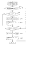
次に、図10から図17のフローチャートを参照して、主制御装置110内のMPU201により実行される各制御処理を説明する。かかるMPU201の処理としては大別して、電源投入に伴い起動される立ち上げ処理と、その立ち上げ処理後に実行されるメイン処理と、定期的に(本実施の形態では2ミリ秒(以下「ms」で表す)周期で)起動されるタイマ割込処理と、NMI端子への停電信号SG1の入力により起動されるNMI割込処理とがあり、説明の便宜上、はじめにタイマ割込処理とNMI割込処理とを説明し、その後立ち上げ処理とメイン処理とを説明する。   Next, each control process executed by the MPU 201 in the main controller 110 will be described with reference to the flowcharts of FIGS. 10 to 17. The processing of the MPU 201 is roughly divided into a startup process activated upon power-on, a main process executed after the startup process, and periodically (in this embodiment, 2 milliseconds (hereinafter “ms”). (Indicated by a period) and a timer interrupt process activated by a period) and an NMI interrupt process activated by the input of the power failure signal SG1 to the NMI terminal. For convenience of explanation, first, the timer interrupt process and the NMI interrupt process After that, the startup process and the main process will be described.

図15は、タイマ割込処理を示したフローチャートである。タイマ割込処理は、主制御装置110のMPU201により例えば2ms毎に実行される。タイマ割込処理では、まず各種入賞スイッチの読み込み処理を実行する(S601)。即ち、主制御装置110に接続されている各種スイッチ(但し、RAM消去スイッチ122(図6参照)を除く)の状態を読み込むと共に、当該スイッチの状態を判定して検出情報(入賞検知情報)を保存する。次に、第1初期値乱数カウンタCINI1と第2初期値乱数カウンタCINI2の更新を実行する(S602)。具体的には、第1初期値乱数カウンタCINI1を1加算すると共に、そのカウンタ値が最大値(本実施の形態では738)に達した際0にクリアする。そして、第1初期値乱数カウンタCINI1の更新値を、RAM203の該当するバッファ領域に格納する。同様に、第2初期値乱数カウンタCINI2を1加算すると共に、そのカウンタ値が最大値(本実施の形態では250)に達した際0にクリアし、その第2初期値乱数カウンタCINI2の更新値をRAM203の該当するバッファ領域に格納する。   FIG. 15 is a flowchart showing the timer interrupt process. The timer interrupt process is executed by the MPU 201 of the main control device 110, for example, every 2 ms. In the timer interruption process, first, reading process of various winning switches is executed (S601). That is, the state of various switches (except for the RAM erase switch 122 (see FIG. 6)) connected to the main controller 110 is read, and the state of the switch is determined to detect detection information (winning detection information). save. Next, the first initial value random number counter CINI1 and the second initial value random number counter CINI2 are updated (S602). Specifically, the first initial value random number counter CINI1 is incremented by 1 and cleared to 0 when the counter value reaches the maximum value (738 in the present embodiment). Then, the updated value of the first initial value random number counter CINI 1 is stored in the corresponding buffer area of the RAM 203. Similarly, the second initial value random number counter CINI2 is incremented by 1 and cleared to 0 when the counter value reaches the maximum value (250 in the present embodiment), and the updated value of the second initial value random number counter CINI2 Is stored in the corresponding buffer area of the RAM 203.

更に、第1当たり乱数カウンタC1、第1当たり種別カウンタC2、停止パターン選択カウンタC3及び第2当たり乱数カウンタC4の更新を実行する(S603)。具体的には、第1当たり乱数カウンタC1、第1当たり種別カウンタC2、停止パターン選択カウンタC3及び第2当たり乱数カウンタC4をそれぞれ1加算すると共に、それらのカウンタ値が最大値(本実施の形態ではそれぞれ、738,4,238,250)に達した際それぞれ0にクリアする。そして、各カウンタC1〜C4の更新値を、RAM203の該当するバッファ領域に格納する。   Further, the first per-random number counter C1, the first per-type counter C2, the stop pattern selection counter C3, and the second per-random number counter C4 are updated (S603). Specifically, 1 is added to each of the first per-random number counter C1, the first per-type counter C2, the stop pattern selection counter C3, and the second per-random number counter C4, and these counter values are the maximum values (this embodiment) Then, when 738, 4, 238, 250) are reached, they are cleared to 0. Then, the updated values of the counters C1 to C4 are stored in the corresponding buffer area of the RAM 203.

その後は、第1入球口64への入賞に伴う始動入賞処理を実行し(S604)、発射制御処理を実行する(S605)。なお、発射制御処理は、遊技者が操作ハンドル51に触れていることをタッチセンサにより検出し、発射を停止させるための発射停止スイッチが操作されていないことを条件に、球の発射のオン/オフを決定する処理である。主制御装置110は、球の発射がオンである場合に、発射制御装置112に対して球の発射指示をする。   Thereafter, a start winning process is performed in accordance with winning in the first entrance 64 (S604), and a launch control process is performed (S605). Note that the launch control process detects that the player is touching the operation handle 51 with a touch sensor and turns on / off the launch of the ball on the condition that the launch stop switch for stopping the launch is not operated. This is a process for determining OFF. The main controller 110 instructs the launch controller 112 to launch a sphere when the launch of the sphere is on.

S606の処理では、大当たり中であるか否かが判別され(S606)、大当たり中でなければ(S606:No)、S607〜S614の処理を行わずにS615の処理へ移行し、大当たり中であれば(S606:Yes)、S607の処理へ移行する。   In the process of S606, it is determined whether or not it is a big hit (S606). If (S606: Yes), the process proceeds to S607.

S607の処理では、開閉扉開放フラグ203aがオンされているか否かが判別される(S607)。開閉扉開放フラグ203aがオンされていれば(S607:Yes)、開閉扉660の開姿勢への指示がなされてからの時間を計時するために、開放タイマ203cの値を1加算し(S608)、開閉扉開放フラグ203aがオフされていれば(S607:No)、開閉扉660の閉姿勢への指示がなされてからの時間を計時するために、閉鎖タイマ203bの値を1加算し(S609)、S610の処理へ移行する。   In the process of S607, it is determined whether or not the open / close door opening flag 203a is turned on (S607). If the opening / closing door opening flag 203a is turned on (S607: Yes), the value of the opening timer 203c is incremented by 1 in order to measure the time after the instruction to open the opening / closing door 660 is given (S608). If the opening / closing door opening flag 203a is turned off (S607: No), the value of the closing timer 203b is incremented by 1 in order to measure the time from when the opening / closing door 660 is instructed to close (S609). ), The process proceeds to S610.

S610の処理では、駆動モータ674の開姿勢または閉姿勢への駆動指示がなされているか否か、及びその駆動指示は高速か低速かが判別され(S610)、駆動モータ674の開姿勢または閉姿勢への駆動指示がなされていなければ(S610:なし)、S611〜S618の駆動モータ674を駆動させるための処理を行わずにS619の処理へ移行する。一方、駆動モータ674を高速で駆動させる駆動指示がなされていれば(S610:高速)、S611の処理へ移行し、駆動モータ674を低速で駆動させる駆動指示がなされていれば(S610:低速)、S615の処理へ移行する。   In the process of S610, it is determined whether or not a drive instruction to open or close the drive motor 674 is given, and whether the drive instruction is high speed or low speed (S610), and the open or closed attitude of the drive motor 674 is determined. If the drive instruction is not issued (S610: none), the process proceeds to S619 without performing the process for driving the drive motor 674 in S611 to S618. On the other hand, if a drive instruction for driving the drive motor 674 at high speed is made (S610: high speed), the process proceeds to S611, and if a drive instruction for driving the drive motor 674 at low speed is made (S610: low speed). , The process proceeds to S615.

S611の処理では、高速駆動モータカウンタ203f1の値が4以上であるか否かが判別される(S611)。これは、本実施形態では、駆動モータ674を高速で駆動するためのパルスが8ms毎に出力され、このタイマ割込み処理が2ms毎に実行されるからである。S611の処理で、高速駆動モータカウンタ203f1の値が4より小さければ(S611:No)、駆動モータ674を駆動するためのパルスを出力するタイミングでないので、高速駆動モータカウンタ203f1の値に1を加算して(S612)、S619の処理へ移行する。一方、高速駆動モータカウンタ203f1の値が4以上であれば(S611:Yes)、駆動モータ674を駆動するためのパルスを出力するタイミングとなるので、主制御装置110から駆動モータ674に流されるコイルa1,a2,b1,b2を変更し(S613)、再度8msを計時するために、高速駆動モータカウンタ203f1の値を初期値(例えば、値0)に設定し(S614)、S619の処理へ移行する。   In the process of S611, it is determined whether or not the value of the high-speed drive motor counter 203f1 is 4 or more (S611). This is because in this embodiment, a pulse for driving the drive motor 674 at a high speed is output every 8 ms, and this timer interruption process is executed every 2 ms. If the value of the high-speed drive motor counter 203f1 is smaller than 4 in the processing of S611 (S611: No), it is not the timing to output a pulse for driving the drive motor 674, so 1 is added to the value of the high-speed drive motor counter 203f1. Then (S612), the process proceeds to S619. On the other hand, if the value of the high-speed drive motor counter 203f1 is 4 or more (S611: Yes), the timing for outputting a pulse for driving the drive motor 674 is reached. a1, a2, b1, b2 are changed (S613), and the value of the high-speed drive motor counter 203f1 is set to an initial value (for example, value 0) in order to measure 8 ms again (S614), and the process proceeds to S619. To do.

S615の処理では、低速駆動モータカウンタ203f2の値が8以上であるか否かが判別される(S615)。これは、本実施形態では、駆動モータ674を低速で駆動するためのパルスが16ms毎に出力され、このタイマ割込み処理が2ms毎に実行されるからである。S615の処理で、低速駆動モータカウンタ203f2の値が8より小さければ(S615:No)、駆動モータ674を駆動するためのパルスを出力するタイミングでないので、低速駆動モータカウンタ203f2の値に1を加算して(S616)、S619の処理へ移行する。一方、低速駆動モータカウンタ203f2の値が8以上であれば(S615:Yes)、駆動モータ674を駆動するためのパルスを出力するタイミングとなるので、主制御装置110から駆動モータ674に流されるコイルa1,a2,b1,b2を変更し(S613)、再度16msを計時するために、低速駆動モータカウンタ203f2の値を初期値(例えば、値0)に設定し(S618)、S619の処理へ移行する。   In the process of S615, it is determined whether or not the value of the low-speed drive motor counter 203f2 is 8 or more (S615). This is because in this embodiment, a pulse for driving the drive motor 674 at a low speed is output every 16 ms, and this timer interrupt process is executed every 2 ms. If the value of the low-speed drive motor counter 203f2 is smaller than 8 in the process of S615 (S615: No), it is not the timing to output a pulse for driving the drive motor 674, so 1 is added to the value of the low-speed drive motor counter 203f2. Then (S616), the process proceeds to S619. On the other hand, if the value of the low-speed drive motor counter 203f2 is 8 or more (S615: Yes), the timing for outputting a pulse for driving the drive motor 674 is reached, so the coil that is passed from the main controller 110 to the drive motor 674 a1, a2, b1, b2 are changed (S613), and the value of the low-speed drive motor counter 203f2 is set to an initial value (for example, value 0) in order to measure 16 ms again (S618), and the process proceeds to S619. To do.

なお、本実施形態では、駆動モータ674を開姿勢または閉姿勢へ駆動させるためのパルス数は60パルスであるので、S613,S617の処理によりコイルa1,a2,b1,b2に流される電流が60回変更された場合に、60パルスが出力されたことになる。また、S610の処理の駆動指示があるか否かの判別は、駆動モータ674の開姿勢または閉姿勢への駆動指示がなされた後に、パルスが60回出力された(コイルの変更が60回行われた)か否かに基づいて行っている。また、パルス数は、図示しないカウンタに記憶されており、S613の処理が実行される毎に、1が加算または減算される。   In the present embodiment, since the number of pulses for driving the drive motor 674 to the open posture or the closed posture is 60 pulses, the current flowing through the coils a1, a2, b1, b2 by the processing of S613 and S617 is 60. When the number of times is changed, 60 pulses are output. Whether or not there is a drive instruction for the processing of S610 is determined by outputting a pulse 60 times after the drive instruction to open or close the drive motor 674 (the coil is changed 60 times). Is done based on whether or not. The number of pulses is stored in a counter (not shown), and 1 is added or subtracted every time the process of S613 is executed.

S619の処理では、特定入賞口検出スイッチ207により球の通過が検出されたか否かが判別される(S619)。S619の処理で、特定入賞口検出スイッチ207により球の通過が検出されていれば(S619:Yes)、特定入賞口カウンタ203dの値に1を加算して(S620)、タイマ割込処理を終了する。一方、特定入賞口検出スイッチ207により球の通過が検出されていなければ(S619:No)、S620の処理を実行せずに、タイマ割込処理を終了する。なお、S619の処理で、特定入賞口検出スイッチ207による球の通過は、特定入賞口検出スイッチ207がオフからオンに変化し、その後オフとなった場合に検出される。   In the process of S619, it is determined whether or not the passage of the ball is detected by the specific winning opening detection switch 207 (S619). If the passage of the ball is detected by the specific winning opening detection switch 207 in the process of S619 (S619: Yes), 1 is added to the value of the specific winning opening counter 203d (S620), and the timer interruption process is finished. To do. On the other hand, if the passage of the ball is not detected by the specific winning opening detection switch 207 (S619: No), the timer interrupt process is terminated without executing the process of S620. In the process of S619, the passage of the ball by the specific winning opening detection switch 207 is detected when the specific winning opening detection switch 207 changes from off to on and then turns off.

ここで、図16を参照して、S604の処理で実行される始動入賞処理を説明する。図16は、タイマ割込処理(図15参照)の中で実行される始動入賞処理(S604)を示したフローチャートである。始動入賞処理が実行されると、まず、球が第1入球口64に入賞(始動入賞)したか否かを判別する(S701)。球が第1入球口64に入賞したと判別されると(S701:Yes)、第1図柄表示装置37の作動保留球数Nが上限値(本実施の形態では4)未満であるか否かを判別する(S702)。第1入球口64への入賞があり、且つ作動保留球数N<4であれば(S702:Yes)、作動保留球数Nを1加算し(S703)、更に、前記ステップS603で更新した第1当たり乱数カウンタC1、第1当たり種別カウンタC2及び停止パターン選択カウンタC3の各値を、RAM203の保留球格納エリアの空き保留エリアのうち最初のエリアに格納する(S704)。一方、第1入球口64への入賞がないか(S701:No)、或いは、第1入球口64への入賞があっても作動保留球数N<4でなければ(S702:No)、S703及びS704の各処理をスキップし、始動入賞処理を終了してタイマ割込処理へ戻る。   Here, with reference to FIG. 16, the start winning process executed in the process of S604 will be described. FIG. 16 is a flowchart showing the start winning process (S604) executed in the timer interrupt process (see FIG. 15). When the start winning process is executed, first, it is determined whether or not the ball has won a first winning opening 64 (start winning prize) (S701). If it is determined that the ball has won the first entrance 64 (S701: Yes), whether or not the number N of the operation reservation balls of the first symbol display device 37 is less than the upper limit (4 in the present embodiment). Is determined (S702). If there is a winning at the first entrance 64 and the number N of activated balls is less than 4 (S702: Yes), the number N of activated balls is incremented by 1 (S703), and further updated in step S603. The values of the first per-random number counter C1, the first per-type counter C2, and the stop pattern selection counter C3 are stored in the first area among the free reserved areas in the reserved ball storage area of the RAM 203 (S704). On the other hand, there is no winning at the first entrance 64 (S701: No), or even if there is a winning at the first entrance 64, if the number N of operational reserves is not less than 4 (S702: No). , S703 and S704 are skipped, the start winning process is terminated, and the process returns to the timer interrupt process.

図17は、NMI割込処理を示したフローチャートである。NMI割込処理は、停電の発生等によるパチンコ機10の電源遮断時に、主制御装置110のMPU201により実行される処理である。このNMI割込処理により、電源断の発生情報がRAM203に記憶される。即ち、停電の発生等によりパチンコ機10の電源が遮断されると、停電信号SG1が停電監視回路252から主制御装置110内のMPU201のNMI端子に出力される。すると、MPU201は、実行中の制御を中断してNMI割込処理を開始し、電源断の発生情報の設定として、電源断の発生情報をRAM203に記憶し(S801)、NMI割込処理を終了する。   FIG. 17 is a flowchart showing the NMI interrupt process. The NMI interruption process is a process executed by the MPU 201 of the main controller 110 when the power of the pachinko machine 10 is shut down due to the occurrence of a power failure or the like. By this NMI interrupt processing, the information on the occurrence of power interruption is stored in the RAM 203. That is, when the power of the pachinko machine 10 is cut off due to the occurrence of a power failure or the like, the power failure signal SG1 is output from the power failure monitoring circuit 252 to the NMI terminal of the MPU 201 in the main controller 110. Then, the MPU 201 interrupts the control being executed and starts the NMI interrupt process, stores the power-off occurrence information in the RAM 203 as a setting of the power-off occurrence information (S801), and ends the NMI interrupt process. To do.

なお、上記のNMI割込処理は、払出発射制御装置111でも同様に実行され、かかるNMI割込処理により、電源断の発生情報がRAM213に記憶される。即ち、停電の発生等によりパチンコ機10の電源が遮断されると、停電信号SG1が停電監視回路252から払出発射制御装置111内のMPU211のNMI端子に出力され、MPU211は実行中の制御を中断して、NMI割込処理を開始するのである。   The above NMI interrupt process is executed in the same manner in the payout and emission control device 111, and information on the occurrence of power interruption is stored in the RAM 213 by the NMI interrupt process. That is, when the power of the pachinko machine 10 is cut off due to the occurrence of a power failure or the like, the power failure signal SG1 is output from the power failure monitoring circuit 252 to the NMI terminal of the MPU 211 in the payout and emission control device 111, and the MPU 211 interrupts the control being executed. Then, the NMI interrupt process is started.

次に、図10を参照して、主制御装置110に電源が投入された場合の立ち上げ処理について説明する。図10は、主制御装置110内のMPU201により実行される立ち上げ処理を示したフローチャートである。この立ち上げ処理は電源投入時のリセットにより起動される。立ち上げ処理では、まず、電源投入に伴う初期設定処理を実行する(S101)。具体的には、スタックポインタに予め決められた所定値を設定すると共に、サブ側の制御装置(音声ランプ制御装置113、払出制御装置111等)が動作可能な状態になるのを待つために、ウェイト処理(本実施の形態では1秒)を実行する。次いで、RAM203のアクセスを許可する(S103)。   Next, referring to FIG. 10, a startup process when the main controller 110 is powered on will be described. FIG. 10 is a flowchart showing start-up processing executed by the MPU 201 in the main controller 110. This start-up process is activated by a reset at power-on. In the start-up process, first, an initial setting process associated with power-on is executed (S101). Specifically, in order to set a predetermined value in the stack pointer and wait for the sub-side control devices (audio lamp control device 113, payout control device 111, etc.) to become operable, Wait processing (in this embodiment, 1 second) is executed. Next, access to the RAM 203 is permitted (S103).

その後は、電源装置115に設けたRAM消去スイッチ122(図6参照)がオンされているか否かを判別し(S104)、オンされていれば(S104:Yes)、処理をS110へ移行する。一方、RAM消去スイッチ122がオンされていなければ(S104:No)、更にRAM203に電源断の発生情報が記憶されているか否かを判別し(S105)、記憶されていなければ(S105:No)、前回の電源遮断時の処理が正常に終わらなかった可能性があるので、この場合にも、処理をS110へ移行する。RAM203に電源断の発生情報が記憶されていれば(S105:Yes)、RAM判定値を算出し(S106)、算出したRAM判定値が正常でなければ(S107:No)、即ち算出したRAM判定値が電源遮断時に保存したRAM判定値と一致しなければ、バックアップされたデータは破壊されているので、かかる場合にも処理をS110へ移行する。なお、前述した通り、RAM判定値は、例えばRAM203の作業領域アドレスにおけるチェックサム値である。このRAM判定値に代えて、RAM203の所定のエリアに書き込まれたキーワードが正しく保存されているか否かによりバックアップの有効性を判断するようにしても良い。   Thereafter, it is determined whether or not the RAM erase switch 122 (see FIG. 6) provided in the power supply device 115 is turned on (S104). If it is turned on (S104: Yes), the process proceeds to S110. On the other hand, if the RAM erasure switch 122 is not turned on (S104: No), it is further determined whether or not the information on occurrence of power interruption is stored in the RAM 203 (S105), and if not stored (S105: No). Since there is a possibility that the process at the time of the previous power-off was not completed normally, the process proceeds to S110 also in this case. If power failure occurrence information is stored in the RAM 203 (S105: Yes), a RAM determination value is calculated (S106). If the calculated RAM determination value is not normal (S107: No), that is, the calculated RAM determination is performed. If the value does not match the RAM determination value stored when the power is shut off, the backed up data has been destroyed, and the process proceeds to S110 even in such a case. As described above, the RAM determination value is, for example, a checksum value at the work area address of the RAM 203. Instead of the RAM determination value, the validity of the backup may be determined based on whether or not the keyword written in a predetermined area of the RAM 203 is correctly stored.

S110の処理では、サブ側の制御装置に対して初期化モードであることを認識させるために、払出制御装置111に対して払出初期化コマンドを送信する(S110)。その後、RAM203の初期化処理(S111、S112)に移行する。   In the processing of S110, a payout initialization command is transmitted to the payout control device 111 in order to make the sub control device recognize that it is in the initialization mode (S110). Thereafter, the process proceeds to initialization processing (S111, S112) of the RAM 203.

上述したように、本パチンコ機10では、例えばホールの営業開始時など、電源投入時にRAMデータを初期化する場合にはRAM消去スイッチ122(図6参照)を押しながら電源が投入される。従って、RAM消去スイッチ122が押されていれば、RAMの初期化処理(S111、S112)に移行する。また、電源断の発生情報が設定されていない場合や、RAM判定値(チェックサム値等)によりバックアップの異常が確認された場合も同様にRAM203の初期化処理に移行する。即ち、S111とS112のRAMの初期化処理では、RAM203の使用領域を0にクリアし(S111)、RAM203の初期値を設定する(S112)。その後、S113の処理へ移行する。   As described above, in the pachinko machine 10, for example, when RAM data is initialized when the power is turned on, such as at the start of business in a hall, the power is turned on while pressing the RAM erase switch 122 (see FIG. 6). Therefore, if the RAM erase switch 122 is pressed, the process proceeds to RAM initialization processing (S111, S112). Similarly, when the information on occurrence of power interruption is not set, or when a backup abnormality is confirmed by the RAM determination value (checksum value or the like), the process proceeds to the initialization process of the RAM 203 in the same manner. That is, in the RAM initialization process of S111 and S112, the used area of the RAM 203 is cleared to 0 (S111), and the initial value of the RAM 203 is set (S112). Thereafter, the process proceeds to S113.

一方、RAM消去スイッチ122がオンされておらず(S104:No)、電源遮断の発生情報が記憶されており(S105:Yes)、更にRAM判定値(チェックサム値等)が正常であれば(S107:Yes)、電源断の発生情報をクリアする(S108)。次に、サブ側の制御装置に対して復帰モードであることを認識させるために、払出制御装置111に対して払出復帰コマンドを送信し(S109)、S113の処理へ移行する。S113の処理では、割込みを許可して、その後、後述するメイン処理に移行する。   On the other hand, if the RAM erase switch 122 is not turned on (S104: No), the occurrence information of the power shutdown is stored (S105: Yes), and if the RAM judgment value (checksum value etc.) is normal ( S107: Yes), the information on occurrence of power interruption is cleared (S108). Next, in order to make the sub-side control device recognize that it is in the return mode, a payout return command is transmitted to the payout control device 111 (S109), and the process proceeds to S113. In the process of S113, an interrupt is permitted, and then the process proceeds to a main process to be described later.

次に、図11を参照して、立ち上げ処理後に実行されるメイン処理について説明する。図11は、主制御装置110内のMPU201により実行されるメイン処理を示したフローチャートである。このメイン処理では遊技の主要な処理が実行される。その概要として、4ms周期の定期処理としてS201〜S206の各処理が実行され、その残余時間でS209,S210のカウンタ更新処理が実行される構成となっている。   Next, with reference to FIG. 11, the main process executed after the start-up process will be described. FIG. 11 is a flowchart showing main processing executed by the MPU 201 in the main control device 110. In this main process, the main process of the game is executed. As an outline, each process of S201 to S206 is executed as a periodic process with a period of 4 ms, and the counter update process of S209 and S210 is executed in the remaining time.

メイン処理においては、まず、前回の処理で更新されたコマンド等の出力データをサブ側の各制御装置に送信する(S201)。具体的には、入賞検知情報の有無を判別し、入賞検知情報があれば払出制御装置111に対して獲得球数に対応する賞球コマンドを送信する。また、第3図柄表示装置81による第3図柄の変動表示に必要な変動パターンコマンド、停止図柄コマンド、停止コマンド、演出時間加算コマンド等を音声ランプ制御装置113に送信する。さらに、球の発射を行う場合に、発射制御装置112に球発射信号を送信する。   In the main processing, first, output data such as a command updated in the previous processing is transmitted to each control device on the sub side (S201). Specifically, the presence / absence of winning detection information is determined, and if there is winning detection information, a winning ball command corresponding to the number of acquired balls is transmitted to the payout control device 111. Further, a variation pattern command, a stop symbol command, a stop command, an effect time addition command, and the like necessary for the variation display of the third symbol by the third symbol display device 81 are transmitted to the sound lamp control device 113. Further, when launching a sphere, a sphere launch signal is transmitted to the launch controller 112.

次に、変動種別カウンタCS1,CS2,CS3の各値を更新する(S202)。具体的には、変動種別カウンタCS1,CS2,CS3を1加算すると共に、それらのカウンタ値が最大値(本実施の形態では198,240,162)に達した際それぞれ0にクリアする。そして、変動種別カウンタCS1,CS2,CS3の更新値を、RAM203の該当するバッファ領域に格納する。   Next, each value of the variation type counters CS1, CS2, CS3 is updated (S202). Specifically, the variation type counters CS1, CS2, CS3 are incremented by 1, and are cleared to 0 when their counter values reach the maximum value (198, 240, 162 in this embodiment). Then, the update values of the variation type counters CS 1, CS 2, and CS 3 are stored in the corresponding buffer area of the RAM 203.

変動種別カウンタCS1,CS2,CS3の更新が終わると、払出制御装置111より受信した賞球計数信号や払出異常信号を読み込み(S203)、第1図柄表示装置37による表示を行うための処理や第3図柄表示装置81による第3図柄の変動パターンなどを設定する変動処理を実行する(S204)。なお、変動処理の詳細は図12を参照して後述する。変動処理の終了後は、大当たり状態である場合において可変入賞装置65の開閉扉660を開放又は閉鎖するための開閉扉開閉処理を実行する(S205)。なお、開閉扉開閉処理の詳細は図14を参照して後述する。   When the update of the variation type counters CS1, CS2 and CS3 is completed, the winning ball counting signal and the payout abnormality signal received from the payout control device 111 are read (S203), and the process for displaying on the first symbol display device 37 is performed. A variation process for setting a variation pattern of the third symbol and the like by the three symbol display device 81 is executed (S204). Details of the variation process will be described later with reference to FIG. After the end of the variation process, an open / close door opening / closing process for opening or closing the open / close door 660 of the variable winning device 65 is executed in the case of the big hit state (S205). The details of the door opening / closing process will be described later with reference to FIG.

次に、第2図柄表示装置82による第2図柄(例えば「○」又は「×」の図柄)の表示制御処理を実行する(S206)。簡単に説明すると、球が第2入球口(スルーゲート)67を通過したことを条件に、その通過したタイミングで第2当たり乱数カウンタC4の値が取得されると共に第2図柄表示装置82の表示部83にて第2図柄の変動表示が実施される。そして、第2当たり乱数カウンタC4の値により第2図柄の抽選が実施され、第2図柄の当たり状態になると、第1入球口64に付随する電動役物が所定時間開放される。   Next, a display control process of the second symbol (for example, the symbol “◯” or “x”) by the second symbol display device 82 is executed (S206). Briefly, on the condition that the ball has passed through the second entrance (through gate) 67, the value of the second random number counter C4 is acquired at the timing of the passage, and the second symbol display device 82 The display unit 83 displays the variation of the second symbol. Then, the lottery of the second symbol is performed according to the value of the second winning random number counter C4, and when the winning state of the second symbol is reached, the electric accessory attached to the first entrance 64 is released for a predetermined time.

その後は、RAM203に電源断の発生情報が記憶されているか否かを判別し(S207)、RAM203に電源断の発生情報が記憶されていなければ(S207:No)、次のメイン処理の実行タイミングに至ったか否か、即ち前回のメイン処理の開始から所定時間(本実施の形態では4ms)が経過したか否かを判別し(S208)、既に所定時間が経過していれば(S208:Yes)、処理をS201へ移行し、前述したS201以降の各処理を繰り返し実行する。一方、前回のメイン処理の開始から未だ所定時間が経過していなければ(S208:No)、所定時間に至るまでの間、即ち次のメイン処理の実行タイミングに至るまでの残余時間内において、第1初期値乱数カウンタCINI1、第2初期値乱数カウンタCINI2及び変動種別カウンタCS1,CS2,CS3の更新を繰り返し実行する(S209,S210)。   After that, it is determined whether or not the power failure occurrence information is stored in the RAM 203 (S207). If the power failure occurrence information is not stored in the RAM 203 (S207: No), the next main process execution timing is determined. It is determined whether or not a predetermined time (4 ms in the present embodiment) has elapsed since the start of the previous main process (S208). If the predetermined time has already elapsed (S208: Yes) ), The process proceeds to S201, and the processes after S201 described above are repeatedly executed. On the other hand, if the predetermined time has not yet elapsed since the start of the previous main process (S208: No), the first time in the remaining time until the predetermined time, that is, the execution timing of the next main process is reached. The updating of the initial value random number counter CINI1, the second initial value random number counter CINI2, and the variation type counters CS1, CS2, and CS3 is repeatedly executed (S209, S210).

まず、第1初期値乱数カウンタCINI1と第2初期値乱数カウンタCINI2との更新を実行する(S209)。具体的には、第1初期値乱数カウンタCINI1と第2初期値乱数カウンタCINI2を1加算すると共に、そのカウンタ値が最大値(本実施の形態では738、250)に達した際0にクリアする。そして、第1初期値乱数カウンタCINI1と第2初期値乱数カウンタCINI2の更新値を、RAM203の該当するバッファ領域にそれぞれ格納する。次に、変動種別カウンタCS1,CS2,CS3の更新を実行する(S210)。具体的には、変動種別カウンタCS1,CS2,CS3を1加算すると共に、それらのカウンタ値が最大値(本実施の形態では198,240,162)に達した際それぞれ0にクリアする。そして、変動種別カウンタCS1,CS2,CS3の更新値を、RAM203の該当するバッファ領域にそれぞれ格納する。   First, the first initial value random number counter CINI1 and the second initial value random number counter CINI2 are updated (S209). Specifically, the first initial value random number counter CINI1 and the second initial value random number counter CINI2 are incremented by 1 and cleared to 0 when the counter value reaches the maximum value (738, 250 in this embodiment). . Then, the updated values of the first initial value random number counter CINI1 and the second initial value random number counter CINI2 are stored in the corresponding buffer areas of the RAM 203, respectively. Next, the fluctuation type counters CS1, CS2, and CS3 are updated (S210). Specifically, the variation type counters CS1, CS2, CS3 are incremented by 1, and are cleared to 0 when their counter values reach the maximum value (198, 240, 162 in this embodiment). Then, the update values of the variation type counters CS1, CS2, and CS3 are stored in the corresponding buffer areas of the RAM 203, respectively.

ここで、S201〜S206の各処理の実行時間は遊技の状態に応じて変化するため、次のメイン処理の実行タイミングに至るまでの残余時間は一定でなく変動する。故に、かかる残余時間を使用して第1初期値乱数カウンタCINI1と第2初期値乱数カウンタCINI2の更新を繰り返し実行することにより、第1初期値乱数カウンタCINI1と第2初期値乱数カウンタCINI2(即ち、第1当たり乱数カウンタC1の初期値、第2当たり乱数カウンタC4の初期値)をランダムに更新することができ、同様に変動種別カウンタCS1,CS2,CS3についてもランダムに更新することができる。   Here, since the execution time of each process of S201 to S206 changes according to the state of the game, the remaining time until the next main process execution timing is not constant and varies. Therefore, by repeatedly performing the update of the first initial value random number counter CINI1 and the second initial value random number counter CINI2 using the remaining time, the first initial value random number counter CINI1 and the second initial value random number counter CINI2 (that is, , The initial value of the first per-random number counter C1 and the initial value of the second per-random number counter C4) can be updated at random. Similarly, the variation type counters CS1, CS2, and CS3 can be updated at random.

また、S207の処理において、RAM203に電源断の発生情報が記憶されていれば(S207:Yes)、S211以降の電源遮断時の処理が実行される。まず、各割込処理の発生を禁止し(S211)、電源が遮断されたことを示す電源遮断通知コマンドを他の制御装置(払出制御装置111や音声ランプ制御装置113など)に対して送信する(S212)。そして、RAM判定値を算出してその値を保存し(S213)、RAM203のアクセスを禁止して(S214)、電源が完全に遮断して処理が実行できなくなるまで無限ループを継続する。ここで、RAM判定値は、例えば、RAM203のバックアップされるスタックエリア及び作業エリアにおけるチェックサム値である。   Further, in the process of S207, if the occurrence information of power interruption is stored in the RAM 203 (S207: Yes), the process at the time of power interruption after S211 is executed. First, the generation of each interrupt process is prohibited (S211), and a power-off notification command indicating that the power has been cut off is transmitted to other control devices (such as the payout control device 111 and the voice lamp control device 113). (S212). Then, the RAM determination value is calculated and stored (S213), the access to the RAM 203 is prohibited (S214), and the infinite loop is continued until the power supply is completely shut down and the process cannot be executed. Here, the RAM determination value is, for example, a checksum value in the stack area and work area to be backed up in the RAM 203.

なお、S207の処理は、S201〜S206で行われる遊技の状態変化に対応した一連の処理の終了時、又は、残余時間内に行われるS209とS210の処理の1サイクルの終了時となるタイミングで実行されている。よって、主制御装置110のメイン処理において、各設定が終わったタイミングで電源断の発生情報を確認しているので、電源遮断の状態から復帰する場合にはS201の処理から開始される状態となっている。即ち、立ち上げ処理において初期化された場合と同様にS201の処理から開始できる状態である。よって、電源遮断時の処理において、MPU201が使用している各レジスタの内容をスタックエリアへ退避したり、スタックポインタの値を保存しなくても、初期設定の処理(S101)において、スタックポインタが所定値(初期値)に設定されることで、S201の処理から開始できる。従って、電源遮断時の処理と立ち上げ時の処理を簡略化できるので、主制御装置110の制御負担を軽減することができると共に、主制御装置110が誤動作したり暴走することなく正確な制御を行うことができる。   It should be noted that the process of S207 is performed at the end of a series of processes corresponding to the game state change performed in S201 to S206, or at the end of one cycle of the processes of S209 and S210 performed within the remaining time. It is running. Therefore, in the main process of the main controller 110, the occurrence information of the power interruption is confirmed at the timing when each setting is completed. Therefore, when returning from the power interruption state, the process starts from the process of S201. ing. That is, it is a state that can be started from the process of S201 as in the case of initialization in the start-up process. Therefore, in the process at power-off, the stack pointer is not stored in the initial setting process (S101) without saving the contents of each register used by the MPU 201 to the stack area or saving the value of the stack pointer. By setting to a predetermined value (initial value), the process can start from S201. Therefore, since the process at the time of power-off and the process at the start-up can be simplified, the control burden on the main controller 110 can be reduced and accurate control can be performed without causing the main controller 110 to malfunction or run away. It can be carried out.

次に、図12を参照して、変動処理(S204)について説明する。図12は、メイン処理(図11参照)の中で実行される変動処理(S204)を示したフローチャートである。変動処理では、まず、今現在大当たり中であるか否かを判別する(S301)。大当たり中としては、大当たりの際に第3図柄表示装置81で表示される大当たり遊技の最中と大当たり遊技終了後の所定時間の最中とが含まれる。判別の結果、大当たり中であれば(S301:Yes)、そのまま本処理を終了する。   Next, the variation process (S204) will be described with reference to FIG. FIG. 12 is a flowchart showing the variation process (S204) executed in the main process (see FIG. 11). In the variation process, first, it is determined whether or not the jackpot is currently being hit (S301). The jackpot includes the jackpot game displayed on the third symbol display device 81 in the jackpot and the middle of a predetermined time after the jackpot game ends. As a result of the determination, if it is a big hit (S301: Yes), this processing is terminated as it is.

大当たり中でなければ(S301:No)、第1図柄表示装置37の表示態様が変動中であるか否かを判別し(S302)、第1図柄表示装置37の表示態様が変動中でなければ(S302:No)、作動保留球数Nが0よりも大きいか否かを判別する(S303)。作動保留球数Nが0であれば(S303:No)、そのまま本処理を終了する。作動保留球数N>0であれば(S303:Yes)、作動保留球数Nを1減算し(S304)、保留球格納エリアに格納されたデータをシフト処理する(S305)。このデータシフト処理は、保留球格納エリアの保留第1〜第4エリアに格納されているデータを実行エリア側に順にシフトさせる処理であって、保留第1エリア→実行エリア、保留第2エリア→保留第1エリア、保留第3エリア→保留第2エリア、保留第4エリア→保留第3エリアといった具合に各エリア内のデータがシフトされる。データシフト処理の後は、第1図柄表示装置37の変動開始処理を実行する(S306)。なお、変動開始処理については図13を参照して後述する。   If it is not a big hit (S301: No), it is determined whether or not the display mode of the first symbol display device 37 is changing (S302), and if the display mode of the first symbol display device 37 is not changing. (S302: No), it is determined whether or not the number N of active suspension balls is greater than 0 (S303). If the number N of active balls is 0 (S303: No), this process is terminated as it is. If the number of the operation hold balls N> 0 (S303: Yes), the operation hold ball number N is decremented by 1 (S304), and the data stored in the hold ball storage area is shifted (S305). This data shift process is a process of sequentially shifting the data stored in the reserved first to fourth areas of the reserved ball storage area to the execution area side, and the reserved first area → execution area, reserved second area → The data in each area is shifted such as the first hold area, the third hold area → the second hold area, the fourth hold area → the third hold area. After the data shift process, the fluctuation start process of the first symbol display device 37 is executed (S306). The variation start process will be described later with reference to FIG.

S302の処理において、第1図柄表示装置37の表示態様が変動中であると判別されると(S302:Yes)、変動時間が経過したか否かを判別する(S307)。第1図柄表示装置37の変動中の表示時間は、変動種別カウンタCS1,CS2により選択された変動パターンと変動種別カウンタCS3により選択された加算時間に応じて決められており、この変動時間が経過していなければ(S307:No)、第1図柄表示装置37の表示を更新する(S308)。本実施の形態では、第1図柄表示装置37のLED37aの内、変動が開始されてから変動時間が経過するまでは、例えば、現在点灯しているLEDが赤であれば、その赤のLEDを消灯すると共に緑のLEDを点灯させ、緑のLEDが点灯していれば、その緑のLEDを消灯すると共に青のLEDを点灯させ、青のLEDが点灯していれば、その青のLEDを消灯すると共に赤のLEDを点灯させる表示態様が設定される。なお、変動処理は、4ms毎に実行されるが、その変動処理毎にLEDの点灯色を変更すると、LEDの点灯色の変化を遊技者が確認することができない。そこで、遊技者にLEDの点灯色の変化を確認させるために、変動処理では、実行される毎にカウンタ(図示せず)を1カウントし、そのカウンタが100に達した場合に、LEDの点灯色の変更を行い、0.4s毎にLEDの点灯色の変更を行っている。なお、カウンタの値は、LEDの点灯色が変更されたらリセット(値0)される。   In the process of S302, if it is determined that the display mode of the first symbol display device 37 is changing (S302: Yes), it is determined whether or not the change time has elapsed (S307). The display time during fluctuation of the first symbol display device 37 is determined according to the fluctuation pattern selected by the fluctuation type counters CS1 and CS2 and the addition time selected by the fluctuation type counter CS3, and this fluctuation time has elapsed. If not (S307: No), the display of the first symbol display device 37 is updated (S308). In the present embodiment, among the LEDs 37a of the first symbol display device 37, for example, if the currently lit LED is red until the variation time elapses after the variation starts, the red LED is Turn off and turn on the green LED. If the green LED is on, turn off the green LED and turn on the blue LED. If the blue LED is on, turn on the blue LED. A display mode for turning off the red LED and turning on the red LED is set. The variation process is executed every 4 ms. However, if the LED lighting color is changed for each variation process, the player cannot confirm the change in the LED lighting color. Therefore, in order to make the player confirm the change of the LED lighting color, in the variation processing, a counter (not shown) is counted by 1 each time it is executed. The color is changed, and the lighting color of the LED is changed every 0.4 s. The counter value is reset (value 0) when the lighting color of the LED is changed.

一方、第1図柄表示装置37の変動時間が経過していれば(S307:Yes)、第1図柄表示装置37の停止図柄に対応した表示態様が設定される(S309)。停止図柄の設定は、第1当たり乱数カウンタC1の値に応じて大当たりか否かが決定されると共に、大当たりである場合には第1当たり種別カウンタC2の値により大当たり後に高確率状態となる図柄か低確率状態となる図柄かが決定される。本実施の形態では、大当たり後に高確率状態になる場合には赤色のLEDを点灯させ、低確率状態になる場合には緑色のLEDを点灯させ、外れである場合には青色のLEDを点灯させる。なお、各LEDの表示は、次の変動表示が開始される場合に点灯が解除されるが、変動の停止後数秒間のみ点灯させるものとしても良い。   On the other hand, if the variation time of the first symbol display device 37 has elapsed (S307: Yes), a display mode corresponding to the stop symbol of the first symbol display device 37 is set (S309). Whether or not the stop symbol is set is determined according to the value of the first random number counter C1, and if it is a big hit, the symbol that becomes a high probability state after the big hit by the value of the first hit type counter C2 Or a symbol that is in a low probability state is determined. In this embodiment, a red LED is turned on when a high probability state is reached after a big hit, a green LED is turned on when a low probability state is reached, and a blue LED is turned on when it is out of place. . In addition, although the lighting of each LED is released when the next fluctuation display is started, it may be turned on only for a few seconds after the fluctuation stops.

S309の処理で停止図柄に対応した第1図柄表示装置37の表示態様が設定されると、第3図柄表示装置81の変動停止を第1図柄表示装置37におけるLEDの点灯と同調させるために停止コマンドが設定される(S310)。この停止コマンドを音声ランプ制御装置113が受信して表示制御装置114に停止指示をする。第3図柄表示装置81は、変動時間が経過すると変動が停止し、停止コマンドを受信することで、第3図柄表示装置81における1の変動演出が終了する。   When the display mode of the first symbol display device 37 corresponding to the stop symbol is set in the processing of S309, the variation stop of the third symbol display device 81 is stopped to synchronize with the lighting of the LED in the first symbol display device 37. A command is set (S310). The sound lamp control device 113 receives this stop command and instructs the display control device 114 to stop. When the variation time elapses, the third symbol display device 81 stops the variation, and receives the stop command, whereby one variation effect in the third symbol display device 81 ends.

次に、図13を参照して変動開始処理を説明する。図13は、変動処理(図12参照)の中で実行される変動開始処理(S306)を示したフローチャートである。変動開始処理(S306)では、まず、保留球格納エリアの実行エリアに格納されている第1当たり乱数カウンタC1の値に基づいて大当たりか否かを判別する(S401)。大当たりか否かは第1当たり乱数カウンタC1の値とその時々のモードとの関係に基づいて判別される。前述した通り通常の低確率時には第1当たり乱数カウンタC1の数値0〜738のうち「373,727」が当たり値であり、高確率時には「59,109,163,211,263,317,367,421,479,523,631,683,733」が当たり値である。   Next, the variation start process will be described with reference to FIG. FIG. 13 is a flowchart showing the change start process (S306) executed in the change process (see FIG. 12). In the variation start process (S306), first, it is determined whether or not a big hit is made based on the value of the first hit random number counter C1 stored in the execution area of the reserved ball storage area (S401). Whether or not it is a big hit is determined based on the relationship between the value of the first random number counter C1 and the mode at that time. As described above, “373,727” is a winning value among the values 0 to 738 of the first random number counter C1 at the normal low probability, and “59,109,163, 211,263,317,367, "421,479,523,631,683,733" is the winning value.

大当たりであると判別された場合(S401:Yes)、保留球格納エリアの実行エリアに格納されている第1当たり種別カウンタC2の値を確認して、大当たり時の表示態様が設定される(S402)。S402の処理では、第1当たり種別カウンタC2の値に基づき、大当たり後に高確率状態に移行するか低確率状態に移行するかが設定される。大当たり後の移行状態が設定されると、第1図柄表示装置37の表示態様(LED37aの点灯状態)が設定される。また、大当たり後の移行状態に基づいて、第3図柄表示装置81で停止表示される大当たりの停止図柄が音声ランプ制御装置113及び表示制御装置114で設定される。即ち、S402の処理で、大当たり後の移行状態を設定することで、第3図柄表示装置81における停止図柄が設定される。なお、第1当たり種別カウンタC2の数値0〜4のうち、「0,4」の場合は以後低確率状態に移行し、「1,2,3」の場合は高確率状態に移行する。   When it is determined that it is a big hit (S401: Yes), the value of the first hit type counter C2 stored in the execution area of the reserved ball storage area is confirmed, and the display mode for the big hit is set (S402). ). In the process of S402, based on the value of the first hit type counter C2, whether to shift to the high probability state or shift to the low probability state after the big hit is set. When the transition state after the big hit is set, the display mode of the first symbol display device 37 (the lighting state of the LED 37a) is set. Further, based on the transition state after the jackpot, the jackpot stop symbol stopped and displayed on the third symbol display device 81 is set by the sound lamp control device 113 and the display control device 114. That is, the stop symbol in the third symbol display device 81 is set by setting the transition state after the big hit in the process of S402. Of the numerical values 0 to 4 of the first hit type counter C2, when “0, 4”, the state shifts to the low probability state, and when “1, 2, 3”, the state shifts to the high probability state.

次に、変動パターンに大当たり時の変動パターンが決定される(S403)。S403の処理で変動パターンが決定されると、第1図柄表示装置37の表示時間が設定されると共に、第3図柄表示装置81において大当たり図柄で停止するまでの第3図柄の変動時間が決定される。具体的には、RAM203のカウンタ用バッファに格納されている変動種別カウンタCS1,CS2の値を確認し、第1変動種別カウンタCS1の値に基づいてノーマルリーチ、スーパーリーチ、プレミアムリーチ等の大まかな図柄変動の変動時間を決定すると共に、第2変動種別カウンタCS2の値に基づいてリーチ発生後に最終停止図柄(本実施の形態では中図柄Z2)が停止するまでの変動時間(言い換えれば、変動図柄数)を決定する。   Next, a variation pattern at the time of big hit is determined as the variation pattern (S403). When the variation pattern is determined in the process of S403, the display time of the first symbol display device 37 is set and the variation time of the third symbol until the third symbol display device 81 stops at the jackpot symbol is determined. The Specifically, the values of the variation type counters CS1 and CS2 stored in the counter buffer of the RAM 203 are confirmed, and rough symbols such as normal reach, super reach, premium reach, etc. are determined based on the value of the first variation type counter CS1. The variation time until the final stop symbol (in this embodiment, middle symbol Z2) stops after the occurrence of reach is determined based on the value of the second variation type counter CS2 (in other words, the number of variation symbols) ).

なお、第1変動種別カウンタCS1の数値と変動時間との関係、第2変動種別カウンタCS2の数値と変動時間との関係は、それぞれにテーブル等により予め定められている。但し、上記変動時間は、第2変動種別カウンタCS2の値を使わずに第1変動種別カウンタCS1の値だけを用いて設定することも可能であり、第1変動種別カウンタCS1の値だけで設定するか又は両変動種別カウンタCS1,CS2の両値で設定するかは、その都度の第1変動種別カウンタCS1の値や遊技条件などに応じて適宜決められる。   The relationship between the numerical value of the first variation type counter CS1 and the variation time, and the relationship between the numerical value of the second variation type counter CS2 and the variation time are predetermined by a table or the like. However, the fluctuation time can be set using only the value of the first fluctuation type counter CS1 without using the value of the second fluctuation type counter CS2, and can be set only with the value of the first fluctuation type counter CS1. Whether or not to set with both values of both variation type counters CS1 and CS2 is appropriately determined according to the value of the first variation type counter CS1 and the game conditions each time.

S401の処理で大当たりではないと判別された場合には(S401:No)、外れ時の表示態様が設定される(S404)。S404の処理では、第1図柄表示装置37の表示態様を外れ図柄に対応した表示態様に設定すると共に、保留球格納エリアの実行エリアに格納されている停止パターン選択カウンタC3の値に基づいて、第3図柄表示装置81において表示させる演出を、前後外れリーチであるか、前後外れ以外リーチであるか、完全外れであるかを設定する。本実施の形態では、上述したように、高確率状態であるか、低確率状態であるか、及び作動保留個数Nに応じて、停止パターン選択カウンタC3の各停止パターンに対応する値の範囲が異なるようテーブルが設定されている。   If it is determined in the process of S401 that it is not a big hit (S401: No), the display mode at the time of disconnection is set (S404). In the process of S404, the display mode of the first symbol display device 37 is set to the display mode corresponding to the off symbol, and based on the value of the stop pattern selection counter C3 stored in the execution area of the reserved ball storage area, An effect to be displayed on the third symbol display device 81 is set to indicate whether the reach is front / rear out of reach, reach other than front / rear out, or complete out. In the present embodiment, as described above, the range of values corresponding to each stop pattern of the stop pattern selection counter C3 depends on whether the state is a high probability state, a low probability state, and the operation suspension number N. Different tables are set up.

次に、変動パターンに外れ時の変動パターンが決定される(S405)。S405の処理で外れ変動パターンが決定されると、第1図柄表示装置37の表示時間が外れ変動パターンに応じて設定されると共に第3図柄表示装置81において外れ図柄が停止するまでの第3図柄の変動時間が決定される。具体的には、S403の処理と同様に、RAM203のカウンタ用バッファに格納されている変動種別カウンタCS1,CS2の値を確認し、第1変動種別カウンタCS1の値に基づいてノーマルリーチ、スーパーリーチ、プレミアムリーチ等の大まかな図柄変動の変動時間を決定すると共に、第2変動種別カウンタCS2の値に基づいてリーチ発生後に最終停止図柄(本実施の形態では中図柄Z2)が停止するまでの変動時間(言い換えれば、変動図柄数)を決定する。   Next, the fluctuation pattern at the time of deviation from the fluctuation pattern is determined (S405). When the deviation variation pattern is determined in the process of S405, the display time of the first symbol display device 37 is set according to the variation variation pattern, and the third symbol until the failure symbol stops in the third symbol display device 81. The variation time is determined. Specifically, as in the process of S403, the values of the variation type counters CS1 and CS2 stored in the counter buffer of the RAM 203 are confirmed, and the normal reach, super reach, and the like are determined based on the value of the first variation type counter CS1. The variation time until the final stop symbol (in the present embodiment, the middle symbol Z2) stops after the occurrence of the reach based on the value of the second variation type counter CS2 while determining the variation time of rough symbol variation such as premium reach (In other words, the number of variable symbols) is determined.

変動パターンが決定されると(S403、S405)、第1及び第2種別カウンタCS1,CS2により決定された変動時間に加減算される演出時間が決定される(S406)。このとき、RAM203のカウンタ用バッファに格納されている第3種別カウンタCS3の値に基づいて演出時間の加減算が決定され、第1図柄表示装置37の表示時間が設定されると共に、第3図柄表示装置81の変動時間が設定される。本実施の形態では、演出時間の加減算の決定は、第3変動種別カウンタCS3の値に応じて、変動表示の時間を変更しない場合と変動表示時間を1秒加算する場合、変動表示時間を2秒加算する場合、変動表示時間を1秒減算する場合との4種類の加算値が決定される。   When the variation pattern is determined (S403, S405), the effect time to be added to or subtracted from the variation time determined by the first and second type counters CS1, CS2 is determined (S406). At this time, the addition / subtraction of effect time is determined based on the value of the third type counter CS3 stored in the counter buffer of the RAM 203, the display time of the first symbol display device 37 is set, and the third symbol display The variation time of the device 81 is set. In the present embodiment, the effect time addition / subtraction is determined according to the value of the third variation type counter CS3 when the variation display time is not changed and when the variation display time is added for one second, the variation display time is set to 2. In the case of adding seconds, four types of addition values are determined for the case of subtracting 1 second from the variable display time.

なお、変動表示時間が加減算される場合には、第3図柄表示装置81で大当たりの期待値が高くなる予告演出(例えば、変動図柄の変動時間を通常より長くしてスベリを伴わせるスベリ演出や予告キャラクタを表示させる演出、1の変動図柄の変動時間を通常より短くして即停止させる演出など)が行われる。また、第1当たり乱数カウンタC1の値が大当たりである場合は、2秒の加算値が選択される確率が高く設定されているので、遊技者は予告演出を確認することで大当たりを期待することができる。   In addition, when the variable display time is added or subtracted, a notice effect that increases the expected value of the jackpot on the third symbol display device 81 (for example, a slip effect that causes the change time of the variable symbol to be longer than usual and is accompanied by a slip) An effect of displaying a notice character, an effect of making the change time of one change symbol shorter than usual, and stopping immediately) are performed. If the value of the first random number counter C1 is a big hit, the probability that an added value of 2 seconds is selected is set high, so that the player expects a big hit by confirming the notice effect. Can do.

次に、S403又はS405の処理で決定された変動パターン(変動時間)に応じて変動パターンコマンドを設定し(S407)、S402又はS404の処理で設定された停止図柄に応じて停止図柄コマンドを設定する(S408)。そして、S406の処理で決定された演出時間の加算値に応じて演出時間加算コマンドを設定して(S409)、変動処理へ戻る。   Next, a variation pattern command is set according to the variation pattern (variation time) determined in S403 or S405 (S407), and a stop symbol command is set according to the stop symbol set in S402 or S404. (S408). Then, an effect time addition command is set according to the added value of the effect time determined in the process of S406 (S409), and the process returns to the variation process.

次に、図14を参照して、開閉扉開閉処理について説明する。なお、図22を参照して、開閉扉開閉処理で指示される駆動モータ674の駆動方法について説明する。図14は、メイン処理(図11参照)の中で実行される開閉扉開閉処理(S205)を示したフローチャートであり、図22は、駆動モータ674に流す電流のタイミングを示したタイミングチャートである。また、図22の横軸tは、時間を示しており、右側に向かうほど時間が経過している。さらに、図22の「H」及び「L」は、コイルに電流が流されているか否かを示しており、「H」の場合に電流が流されている状態となり、「L」の場合に電流が流されていない状態となる。   Next, the door opening / closing process will be described with reference to FIG. In addition, with reference to FIG. 22, the drive method of the drive motor 674 instruct | indicated by the opening-and-closing door opening / closing process is demonstrated. FIG. 14 is a flowchart showing the open / close door opening / closing process (S205) executed in the main process (see FIG. 11), and FIG. . In addition, the horizontal axis t in FIG. 22 indicates time, and the time elapses toward the right side. Furthermore, “H” and “L” in FIG. 22 indicate whether or not a current is flowing through the coil. When “H”, the current is flowing, and when “L”, No current is flowing.

開閉扉開閉処理が実行されると、実行されている遊技状態が大当たり中であるか否かが判別され(S501)、大当たり中でなければ(S501:No)、閉鎖タイマ203b、開放タイマ203c、特定入賞カウンタ203d及びラウンドカウンタ203eに記憶される値に初期値を設定して(S516)、開閉扉開閉処理を終了する。   When the open / close door opening / closing process is executed, it is determined whether or not the gaming state being executed is a big hit (S501). If it is not a big hit (S501: No), the closing timer 203b, the opening timer 203c, Initial values are set to the values stored in the specific winning counter 203d and the round counter 203e (S516), and the door opening / closing process is ended.

S516の処理は、大当たりの開始時に各タイマ及びカウンタの値を初期値にするために設けられている。そのため、S516の処理に代えて、S501の処理とS502の処理との間に、大当たりの開始時かを判別する処理と、各タイマ及びカウンタの値を初期値に設定する初期値設定処理(S516の処理と同じ処理)を追加し、大当たりの開始時である場合(初回)のみ初期値設定処理を実行するものとしても良い。   The processing of S516 is provided to set the values of the timers and counters to initial values at the start of the jackpot. Therefore, instead of the process of S516, a process for determining whether or not the big hit is started between the process of S501 and the process of S502, and an initial value setting process for setting the values of the respective timers and counters to initial values (S516) The initial value setting process may be executed only when the jackpot is started (first time).

一方、S501の処理で、実行されている遊技状態が大当たり中であれば(S501:No)、開閉扉開放フラグ203aがオンであるか否かが判別され(S502)、開閉扉開放フラグ203aがオフであれば(S502:No)、大当たりの開始時で開閉扉660が閉姿勢の状態であるか、又は、1ラウンドが終わり開閉扉660が閉姿勢となった状態である。そのため、開閉扉660を開姿勢へ動作する前に、開閉扉660が完全に閉姿勢の状態となっているか否かを確認するために、閉鎖タイマ203bに記憶される値が1.5sに対応した値(本実施形態では、2ms毎のタイマ割込み処理で1ずつカウントアップ(S609参照)されるので、閉鎖タイマ203dの値が750)より大きいか否かが判別される(S503)。なお、本実施形態では、後述するが、開閉扉660の開姿勢から閉姿勢への動作は約1sで終了し、閉姿勢から開姿勢への動作は約0.5sで終了する。そのため、S503の処理で、閉鎖タイマ203bの値と比較される値が、次の閉姿勢から開姿勢への動作の遅延時間を含めて1.5sに設定されている。   On the other hand, if the gaming state being executed is a big hit in the process of S501 (S501: No), it is determined whether or not the open / close door opening flag 203a is on (S502), and the open / close door opening flag 203a is set. If it is off (S502: No), the door 660 is in the closed position at the start of the jackpot, or the door 660 is in the closed position after one round. Therefore, the value stored in the closing timer 203b corresponds to 1.5 s in order to confirm whether or not the opening / closing door 660 is in the completely closed position before the opening / closing door 660 is moved to the open position. It is determined whether or not the value of the closing timer 203d is greater than 750) (in this embodiment, since it is counted up by 1 in the timer interrupt process every 2 ms (see S609) in this embodiment) (S503). In this embodiment, as will be described later, the operation of the open / close door 660 from the open posture to the closed posture is completed in about 1 s, and the operation from the closed posture to the open posture is completed in about 0.5 s. Therefore, the value compared with the value of the closing timer 203b in the processing of S503 is set to 1.5 s including the delay time of the operation from the next closing posture to the opening posture.

S503の処理で、閉鎖タイマ203bに記憶される値が1.5sに対応した値より大きければ(S503:Yes)、開閉扉660が既に閉姿勢となっているので、駆動モータ674の開方向への駆動が開始される(S504)。S504の処理では、駆動モータ674の駆動方向(開方向)と、駆動速度(高速)と、その開方向へ所定角度回転駆動させるパルス数(60パルス)が設定される。そのS504の処理で設定されたパルス数に応じて、タイマ割込み処理(図15参照)内で8ms毎に駆動モータ674が1パルス分ずつ駆動され、開閉扉660が開姿勢となる方向(矢印A方向(図4(b)参照))に回動される。即ち、8ms間隔が60回繰り返されるので、60×8ms=480msとなり、約0.5sで開閉扉660が開姿勢へ回動する。また、開閉扉660は、誘導部663が閉姿勢の状態から収容空間677側に約108°(=60×1.8°)回動するので、開閉扉660は開姿勢の状態で特定入賞口672方向に下降傾斜し、球が誘導され易くなっている。   If the value stored in the closing timer 203b is larger than the value corresponding to 1.5 s in the processing of S503 (S503: Yes), the door 660 is already in the closed position, so that the drive motor 674 is opened. Is started (S504). In the process of S504, the driving direction (opening direction) of the driving motor 674, the driving speed (high speed), and the number of pulses (60 pulses) that are rotated by a predetermined angle in the opening direction are set. In the timer interrupt process (see FIG. 15), the drive motor 674 is driven by one pulse every 8 ms in accordance with the number of pulses set in the process of S504, and the direction in which the open / close door 660 is in the open position (arrow A) It is rotated in the direction (see FIG. 4B). That is, since the 8 ms interval is repeated 60 times, 60 × 8 ms = 480 ms, and the open / close door 660 rotates to the open posture in about 0.5 s. Further, the opening / closing door 660 rotates about 108 ° (= 60 × 1.8 °) toward the accommodation space 677 from the state where the guiding portion 663 is in the closed posture, so that the opening / closing door 660 is in the open posture with the specific winning opening. It tilts downward in the direction 672, making it easy to guide the sphere.

具体的には、図22(a)に示すように、まず、コイルa1に電流を流し、その後、コイルb1、コイルa2、コイルb2の順番に電流を流す。コイルa1には、8ms〜16msの間に電流が流され、コイルb1には、16ms〜24msの間に電流が流され、コイルa2には、24ms〜32msの間に電流が流され、コイルb2には、32ms〜40msの間に電流が流される。さらに、コイルa1には、40ms〜48msの間に電流が流され、コイルb1には、48ms〜56msの間に電流が流されている。この各コイルa1,b1,a2,b2に繰り返し電流が流されることで、駆動モータ674が駆動され、開閉扉660が閉姿勢から開姿勢の方向に回動される。   Specifically, as shown in FIG. 22A, first, a current is supplied to the coil a1, and then a current is supplied in the order of the coil b1, the coil a2, and the coil b2. A current flows through the coil a1 between 8 ms and 16 ms, a current flows through the coil b1 between 16 ms and 24 ms, a current flows through the coil a2 between 24 ms and 32 ms, and a coil b2 Current flows between 32 ms and 40 ms. Furthermore, a current flows through the coil a1 between 40 ms and 48 ms, and a current flows through the coil b1 between 48 ms and 56 ms. When a current is repeatedly passed through the coils a1, b1, a2, and b2, the drive motor 674 is driven, and the open / close door 660 is rotated from the closed position to the open position.

駆動モータ674の開方向への駆動が開始されると、開閉扉660の開姿勢への指示がなされてからの時間を計時するために、開放タイマ203cに記憶される値を初期値に設定し(S505)、開閉扉開放フラグ203aをオンして(S506)、S507の処理へ移行する。   When driving in the opening direction of the drive motor 674 is started, the value stored in the opening timer 203c is set to an initial value in order to measure the time from when the opening / closing door 660 is instructed to open. (S505), the opening / closing door opening flag 203a is turned on (S506), and the process proceeds to S507.

一方、S502の処理で、既に開閉扉開放フラグ203aがオンされていれば(S502:Yes)、開閉扉660が開姿勢となっている(又は開姿勢への駆動中となっている)ので、S503〜S506の処理を実行せずにS507の処理へ移行する。また、S503の処理で、閉鎖タイマ203bに記憶される値が1.5sに対応する値に達していなければ(S503:No)、開閉扉660が閉姿勢となった後に遅延時間が経過していないので、S503〜S506の処理を行わずにS507の処理へ移行する。   On the other hand, if the opening / closing door opening flag 203a is already turned on in the processing of S502 (S502: Yes), the opening / closing door 660 is in the open posture (or is being driven to the open posture). The process proceeds to S507 without executing the processes in S503 to S506. If the value stored in the closing timer 203b does not reach the value corresponding to 1.5 s in the processing of S503 (S503: No), the delay time has elapsed after the opening / closing door 660 is closed. Therefore, the process proceeds to S507 without performing the processes in S503 to S506.

S507の処理では、特定入賞カウンタ203dに記憶される値が10より小さいか否かが判別される(S507)。これは、本実施形態の大当たり中の1ラウンドは、10個の球の入賞(通過)が検出されると終了するからである。そのため、特定入賞カウンタ203dに記憶される値が10以上となると(S507:No)、S509〜S513の1ラウンドの終了処理を実行する。   In the process of S507, it is determined whether or not the value stored in the specific winning counter 203d is smaller than 10 (S507). This is because one round in the jackpot of the present embodiment ends when a winning (passing) of 10 balls is detected. For this reason, when the value stored in the specific winning counter 203d is 10 or more (S507: No), one round end processing of S509 to S513 is executed.

S509〜S514の処理では、まず、駆動モータ674を閉方向へ駆動させる(S509)。S509の処理では、上述したS504の処理と同様に、駆動モータ674の駆動方向(閉方向)と、駆動速度(低速)と、その閉方向へ所定角度回転駆動させるパルス数(60パルス)が設定され、開閉扉660が開姿勢から閉姿勢となる方向(矢印B方向(図5(b)参照))に回動する。駆動モータ674の閉方向への駆動が開始されると、開閉扉660が閉姿勢になるまでの時間を計時するために、閉鎖タイマ203bに記憶されている値を初期値に設定し(S510)、駆動モータ674の閉姿勢への動作が完了したか否かが判別される(S511)。なお、S511の処理では、駆動モータ674を閉姿勢へ動作させるパルス(図15のS617の処理でコイルが変更される回数)が、60回に達したか否かに基づいて判別される。S511の処理で、駆動モータ674の閉姿勢への動作が完了していなければ(S511:No)、S515の処理へ移行し、駆動モータ674の閉姿勢への動作が完了していれば(S511:Yes)、開閉扉開放フラグ203aをオフして(S512)、特定入賞カウンタ203dに記憶されている値を初期値に設定し(S513)、開閉扉660が閉姿勢に回動すると、1のラウンドが終了したことになるので、ラウンドカウンタ203eの値に1を加算して(S514)、S515の処理へ移行する。   In the processing of S509 to S514, first, the drive motor 674 is driven in the closing direction (S509). In the process of S509, similarly to the process of S504 described above, the drive direction (closed direction) of the drive motor 674, the drive speed (low speed), and the number of pulses (60 pulses) that are rotated by a predetermined angle in the close direction are set. Then, the opening / closing door 660 rotates in the direction from the open position to the closed position (the direction of arrow B (see FIG. 5B)). When driving of the drive motor 674 in the closing direction is started, the value stored in the closing timer 203b is set to the initial value in order to measure the time until the door 660 is in the closed position (S510). Then, it is determined whether or not the operation of the drive motor 674 to the closed posture is completed (S511). In the process of S511, the determination is made based on whether or not the number of times that the pulse for changing the drive motor 674 to the closed posture (the number of times the coil is changed in the process of S617 in FIG. 15) has reached 60. If the operation of the drive motor 674 to the closed position is not completed in the process of S511 (S511: No), the process proceeds to S515, and if the operation of the drive motor 674 to the closed position is completed (S511). : Yes), the open / close door opening flag 203a is turned off (S512), the value stored in the specific winning counter 203d is set to the initial value (S513), and when the open / close door 660 rotates to the closed position, 1 Since the round has ended, 1 is added to the value of the round counter 203e (S514), and the process proceeds to S515.

なお、S509の処理では、主制御装置110のタイマ割込み処理(図15参照)内で16ms毎に駆動モータ674が1パルスずつ駆動されて、開閉扉660が閉姿勢となる方向(矢印B方向(図5(b)参照))に回動される。即ち、16ms間隔が60回繰り返されるので、60×16ms=960msとなり、約1sで開閉扉660が閉姿勢へ回動する。よって、本実施形態では、開閉扉660が閉姿勢から開姿勢(矢印A方向)に回動する場合の駆動速度より、開閉扉660が開姿勢から閉姿勢(矢印B方向)に回動する場合の駆動速度の方が遅くなるように設定されている。   In the process of S509, the driving motor 674 is driven by one pulse every 16 ms in the timer interrupt process (see FIG. 15) of the main controller 110, and the opening / closing door 660 is in the closed position (arrow B direction (direction B ( 5))). That is, since the 16 ms interval is repeated 60 times, 60 × 16 ms = 960 ms, and the opening / closing door 660 rotates to the closed position in about 1 s. Therefore, in the present embodiment, when the opening / closing door 660 rotates from the open position to the closed position (arrow B direction) by the driving speed when the open / close door 660 rotates from the closed position to the open position (direction of arrow A). The drive speed is set to be slower.

具体的には、図22(b)に示すように、まず、コイルb2に電流を流し、その後、コイルa2、コイルb1、コイルa1の順番に電流を流す。コイルb2には、8ms〜24msの間に電流が流され、コイルa2には、24ms〜40msの間に電流が流され、コイルb1には、40ms〜56msの間に電流が流され、コイルa1には、56ms〜72msの間に電流が流されている。この各コイルb2,a2,b1,a1に繰り返し電流が流されることで、駆動モータ674が駆動され、開閉扉660が開姿勢から閉姿勢の方向に回動される。   Specifically, as shown in FIG. 22B, first, a current is passed through the coil b2, and then a current is passed in the order of the coil a2, the coil b1, and the coil a1. A current flows through the coil b2 between 8 ms and 24 ms, a current flows through the coil a2 between 24 ms and 40 ms, a current flows through the coil b1 between 40 ms and 56 ms, and a coil a1 The current flows between 56 ms and 72 ms. When a current is repeatedly passed through each of the coils b2, a2, b1, and a1, the drive motor 674 is driven, and the open / close door 660 is rotated from the open position to the closed position.

また、S507の処理で、特定入賞カウンタ203dに記憶されている値が10より小さければ(S507:Yes)、未だ、所定個数の球の入賞が検出されていないので、次に、開放タイマ203cに記憶される値が30sに対応した値(本実施形態では、2ms毎のタイマ割込み処理で1ずつカウントアップされる(S608参照)より大きいか否かが判別される(S508)。なお、S508の処理で開放タイマ203cに記憶される値を確認しているのは、本実施形態の1ラウンドの終了が、特定入賞672に10個以上の球が入賞した場合か、開閉扉660が30s以上開姿勢となった場合であるかである。   Further, if the value stored in the specific winning counter 203d is smaller than 10 in the processing of S507 (S507: Yes), the winning of the predetermined number of balls has not yet been detected. It is determined whether or not the stored value is larger than the value corresponding to 30 s (in this embodiment, incremented by 1 in the timer interrupt process every 2 ms (see S608)) (S508). The value stored in the opening timer 203c is confirmed in the processing because the end of one round of the present embodiment is when 10 or more balls are won in the specific winning 672 or the open / close door 660 is opened for 30 seconds or more. Whether it is a posture.

S508の処理で、開放タイマ203cに記憶される値が30sに対応した値より大きければ(S508:Yes)、10個の球の入賞が検出された場合(S507:No)と同様に、S509〜S513の1ラウンドの終了処理を実行し、開放タイマ203cに記憶される値が30sに対応した値に達していなければ(S508:No)、S509〜S514の処理を行わずに、S515の処理へ移行する。   If the value stored in the release timer 203c is larger than the value corresponding to 30 s in the processing of S508 (S508: Yes), S509 to S509 are performed as in the case where a winning of 10 balls is detected (S507: No). The one-round end process of S513 is executed, and if the value stored in the release timer 203c has not reached the value corresponding to 30 s (S508: No), the process proceeds to S515 without performing the processes of S509 to S514. Transition.

S515の処理では、ラウンドカウンタ203eに記憶されている値が16以上となった否かが判別され(S515)、ラウンドカウンタ203eに記憶されている値が16以上であれば(S515:Yes)、大当たり中に行われるラウンド数が終了したことになるので、大当たりの終了を指示して(S516)、開閉扉開閉処理を終了する。一方、ラウンドカウンタ203eに記憶されている値が16より小さければ(S515:No)、大当たり中に行われるラウンド数が終了していないので、S516の処理を行わずに、開閉扉開閉処理を終了する。   In the process of S515, it is determined whether or not the value stored in the round counter 203e is 16 or more (S515). If the value stored in the round counter 203e is 16 or more (S515: Yes), Since the number of rounds performed during the jackpot has ended, the end of the jackpot is instructed (S516), and the door opening / closing process is ended. On the other hand, if the value stored in the round counter 203e is smaller than 16 (S515: No), the number of rounds performed during the jackpot is not completed, so the opening / closing door opening / closing process is terminated without performing the process of S516. To do.

以上、開閉扉開閉処理で説明したように、開閉扉660が開姿勢の状態で、特定入賞口672への入賞数が10個に達すると、開閉扉660を開姿勢から閉姿勢に駆動させている。また、図5(b)に示したように、特定入賞口672の直ぐ下流側に特定入賞口検出スイッチ207が配設されているので、特定入賞口672を通過した球はその通過が早期に検出される。よって、特定入賞口672への入賞数が10個に達したら早期に開閉扉660を閉姿勢へ駆動できるので、開閉扉660の誘導部663(収容空間677)に位置する球を特定入賞口672に未入賞とすることができ、ほぼ毎回10個の入賞数とすることができる。なお、特定入賞口672と特定入賞口検出スイッチ207とは、極力近づけた方が球の通過を早期に検出できるので、特定入賞口672に特定入賞口検出スイッチ207を設ける構成としても良い。   As described above, as described in the door opening / closing process, when the number of winnings in the specific winning opening 672 reaches 10 in the state where the door 660 is in the open posture, the door 660 is driven from the open posture to the closed posture. Yes. Further, as shown in FIG. 5 (b), since the specific winning port detection switch 207 is disposed immediately downstream of the specific winning port 672, the ball passing through the specific winning port 672 is quickly passed. Detected. Therefore, since the door 660 can be driven to the closed position at an early stage when the number of winnings in the specific winning opening 672 reaches 10, the ball located in the guide portion 663 (accommodating space 677) of the opening / closing door 660 is moved to the specific winning opening 672. The number of winnings can be made almost 10 times each time. It should be noted that the specific winning opening 672 and the specific winning opening detection switch 207 can detect the passage of the ball at an early stage as close as possible, so that the specific winning opening detection switch 207 may be provided in the specific winning opening 672.

また、開閉扉660が閉姿勢から開姿勢に回動する場合の駆動速度より、開閉扉660が開姿勢から閉姿勢に回動する場合の駆動速度の方が遅くなっており、その閉姿勢に回動する駆動速度は球のばたつきを抑制できる速度となるので、開閉扉660が開姿勢から閉姿勢へ回動して収容空間677に位置する未入賞の球を遊技領域に排出する際に、球をスムーズに遊技領域に排出できる、開閉扉660の誘導部663の先端と開口651との間で球が挟まれることを低減できる。その結果、開閉扉660が閉姿勢まで回動できずに開口651が開放されたままの状態となることを抑制できるので、収容空間677内に必要以上の球が流入することを抑制でき、必要以上の球が特定入賞口672に入賞することを低減することができる。   In addition, the driving speed when the door 660 rotates from the open position to the closed position is slower than the driving speed when the door 660 rotates from the closed position to the open position. Since the rotational driving speed is a speed at which flapping of the ball can be suppressed, when the open / close door 660 rotates from the open position to the closed position and discharges the unwinned ball located in the accommodation space 677 to the game area, It can be reduced that the ball is sandwiched between the front end of the guide portion 663 of the opening / closing door 660 and the opening 651 so that the ball can be smoothly discharged to the game area. As a result, the opening / closing door 660 can be prevented from rotating to the closed posture and the opening 651 can be prevented from being left open, so that it is possible to suppress the flow of more balls than necessary into the accommodation space 677. It is possible to reduce the above-mentioned balls from winning the specific winning opening 672.

また、開閉扉660が開姿勢から閉姿勢へ駆動すると、開閉扉660が収容空間677から遊技領域側に徐々に下降傾斜するので、収容空間677内の球はスムーズに遊技領域に排出されると共に、球受け部664によって受け止められた球は誘導部663に誘導されることなく遊技領域に排出される。よって、開閉扉660が開姿勢から閉姿勢に回動する際に、収容空間677に流入される数が減少するので、開閉扉660の誘導部663の先端と開口651との間で球が挟まれることを低減でき、必要以上の球が特定入賞口672に入賞することを低減することができる。   Further, when the opening / closing door 660 is driven from the open position to the closed position, the opening / closing door 660 gradually tilts downward from the accommodation space 677 toward the game area, so that the balls in the accommodation space 677 are smoothly discharged to the game area. The ball received by the ball receiving portion 664 is discharged to the game area without being guided by the guiding portion 663. Therefore, when the open / close door 660 rotates from the open position to the closed position, the number of flows into the accommodation space 677 decreases, so that a ball is sandwiched between the tip of the guide portion 663 of the open / close door 660 and the opening 651. It can be reduced, and it is possible to reduce that more than necessary balls win the specific winning opening 672.

次に、図18及び図19を参照して、払出制御装置111内のMPU211により実行される払出制御について説明する。図18は、払出制御装置111の立ち上げ処理を示したフローチャートであり、この立ち上げ処理は電源投入時に起動される。まず、電源投入に伴う初期設定処理を実行する(S901)。具体的には、スタックポインタに予め決められた所定値を設定すると共に、割込みモードを設定する。そして、RAMアクセスを許可すると共に(S902)、外部割込ベクタの設定を行う(S903)。   Next, payout control executed by the MPU 211 in the payout control device 111 will be described with reference to FIGS. 18 and 19. FIG. 18 is a flowchart showing a start-up process of the payout control apparatus 111, and this start-up process is activated when the power is turned on. First, initial setting processing accompanying power-on is executed (S901). Specifically, a predetermined value set in advance is set in the stack pointer, and an interrupt mode is set. Then, the RAM access is permitted (S902), and an external interrupt vector is set (S903).

その後は、MPU211内のRAM213に関してデータバックアップの処理を実行する。具体的には、RAM213に電源断の発生情報が記憶されているか否かを判別し(S904)、記憶されていなければ(S904:No)、前回の電源遮断時の処理が正常に終わらなかった可能性があるので、処理をS910へ移行する。RAM213に電源断の発生情報が記憶されていれば(S904:Yes)、RAM判定値を算出し(S905)、算出したRAM判定値が正常でなければ(S905:No)、即ち算出したRAM判定値が電源遮断時に保存したRAM判定値と一致しなければ、バックアップされたデータは破壊されているので、かかる場合にも処理をS910へ移行する。なお、前述した通り、RAM判定値は、例えばRAM213の作業領域アドレスにおけるチェックサム値である。このRAM判定値に代えて、RAM213の所定のエリアに書き込まれたキーワードが正しく保存されているか否かによりバックアップの有効性を判断するようにしても良い。   After that, data backup processing is executed for the RAM 213 in the MPU 211. Specifically, it is determined whether or not the information on occurrence of power interruption is stored in the RAM 213 (S904). If not stored (S904: No), the process at the time of the previous power interruption was not completed normally. Since there is a possibility, the process proceeds to S910. If power failure occurrence information is stored in the RAM 213 (S904: Yes), a RAM determination value is calculated (S905). If the calculated RAM determination value is not normal (S905: No), that is, the calculated RAM determination is performed. If the value does not match the RAM determination value stored when the power is turned off, the backed up data has been destroyed. In such a case as well, the process proceeds to S910. As described above, the RAM determination value is, for example, a checksum value at the work area address of the RAM 213. Instead of the RAM determination value, the validity of the backup may be determined based on whether or not the keyword written in a predetermined area of the RAM 213 is correctly stored.

S910の処理〜S912の処理のRAMの初期化処理では、RAM213の全ての領域を0にクリアし(S910)、RAM213の初期値を設定する(S911)。その後、MPU211周辺デバイスの初期設定を行い(S912)、S913の処理へ移行し割込みを許可してメイン処理へ移行する。   In the RAM initialization process from S910 to S912, all areas of the RAM 213 are cleared to 0 (S910), and the initial value of the RAM 213 is set (S911). Thereafter, the MPU 211 peripheral device is initialized (S912), the process proceeds to S913, an interrupt is permitted, and the process proceeds to the main process.

一方、電源断の発生情報が設定されており(S904:Yes)、且つRAM判定値(チェックサム値等)が正常であれば(S906:Yes)、電源遮断の発生情報をクリアすると共に(S907)、賞球の払出を許可する払出許可フラグをクリアする(S908)。また、MPU211周辺デバイスの初期設定を行い(S909)、S913の処理へ移行し割込みを許可してメイン処理へ移行する。   On the other hand, if the power-off occurrence information is set (S904: Yes) and the RAM determination value (checksum value etc.) is normal (S906: Yes), the power-off occurrence information is cleared (S907). ), The payout permission flag for permitting the payout of the prize ball is cleared (S908). In addition, the MPU 211 peripheral device is initialized (S909), the process proceeds to S913, an interrupt is permitted, and the process proceeds to the main process.

図19は、払出制御装置111内のMPU211により実行されるメイン処理を示したフローチャートである。このメイン処理は、まず主制御装置110からの賞球コマンドや発射制御装置112へ送信されるコマンドなどを取得し、そのコマンドの判定処理を行う(S1001)。コマンド判定処理では、主制御装置110から送信されるコマンド(払出初期化コマンド、払出復電コマンド、賞球コマンドなど)を受信すると払出許可フラグがオンされ払い出しが許可される。   FIG. 19 is a flowchart showing main processing executed by the MPU 211 in the payout control apparatus 111. In the main process, first, a prize ball command from the main control device 110, a command transmitted to the firing control device 112, and the like are acquired, and a determination process for the command is performed (S1001). In the command determination process, when a command (a payout initialization command, a payout power recovery command, a prize ball command, etc.) transmitted from the main control device 110 is received, a payout permission flag is turned on and payout is permitted.

コマンド判定処理(S1001)が終わると、払い出しが許可されているか否かが判別され(S1002)、払い出しが許可されていなければ(S1002:No)、コマンド判定処理(S1001)において払い出しが許可されるまでコマンド判定処理(S1001)を繰り返し実行する。一方、S1002の処理において払い出しが許可されていれば(S1002:Yes)、状態復帰スイッチ120(図6参照)をチェックし状態復帰動作開始と判定した場合に状態復帰動作を実行する(S1003)。状態復帰動作とは、例えば、払出モータ216(図7参照)部の球詰まり等、払出エラーの発生時に球詰まりを解消(正常状態への復帰)する動作である。   When the command determination process (S1001) ends, it is determined whether or not the payout is permitted (S1002). If the payout is not permitted (S1002: No), the payout is permitted in the command determination process (S1001). Until the command determination process (S1001) is repeated. On the other hand, if payout is permitted in the process of S1002 (S1002: Yes), the state return operation is executed when the state return switch 120 (see FIG. 6) is checked and it is determined that the state return operation starts (S1003). The state returning operation is an operation for eliminating the ball clogging (returning to a normal state) when a payout error occurs such as a ball clogging in the payout motor 216 (see FIG. 7).

その後、下皿50(図1参照)の状態の変化に応じて下皿満タン状態又は下皿満タン解除状態の設定を実行する(S1004)。即ち、下皿満タンスイッチ(図示せず)の検出信号により下皿50の満タン状態を判別し、下皿満タンになった時に、下皿満タン状態の設定を実行し、下皿満タンでなくなった時に、下皿満タン解除状態の設定を実行する。また、タンク球の状態の変化に応じてタンク球無し状態又はタンク球無し解除状態の設定を実行する(S1005)。即ち、タンク球無しスイッチ(図示せず)の検出信号によりタンク球無し状態を判別し、タンク球無しになった時に、タンク球無し状態の設定を実行し、タンク球無しでなくなった時に、タンク球無し解除状態の設定を実行する。その後、報知する状態の有無を判別し、報知する状態が有る場合には払出制御装置111に設けた7セグメントLED(図示せず)により報知する(S1006)。   Thereafter, setting of the lower plate full state or the lower plate full state is performed according to the change in the state of the lower plate 50 (see FIG. 1) (S1004). In other words, the full state of the lower pan 50 is determined based on a detection signal from a lower pan full switch (not shown), and when the lower pan is full, the lower pan full state is set. When the tank has run out, set the lower pan full tank release state. Further, the setting of the tank ball absence state or the tank ball absence release state is executed according to the change in the state of the tank ball (S1005). That is, the tank ball no switch state (not shown) is detected based on the detection signal of the tank ball, and when no tank ball is found, the tank ball no state setting is executed. Executes the setting of the no ball release state. Thereafter, the presence / absence of a notification state is determined, and if there is a notification state, notification is made by a 7-segment LED (not shown) provided in the payout control device 111 (S1006).

次に、S1007〜S1009の各処理により、賞球払出の処理を実行する。即ち、賞球の払出不可状態でなく且つ記憶した総賞球個数が0でなければ(S1007:No,S1008:No)、賞球の払い出しを行うために賞球制御処理を開始する(S1009)。一方、賞球の払出不可状態(S1007:Yes)または総賞球個数が0であれば(S1008:Yes)、貸球払出の処理に移行する。   Next, prize ball payout processing is executed by each processing of S1007 to S1009. That is, if the total number of prize balls is not 0 (S1007: No, S1008: No), the prize ball control process is started in order to pay out the prize balls (S1009). . On the other hand, if the prize ball cannot be paid out (S1007: Yes) or if the total number of prize balls is 0 (S1008: Yes), the process proceeds to the lending and payout process.

S1010〜S1012の貸球払出の処理では、貸球の払出不可状態でなく且つカードユニットからの貸球払出要求を受信していれば(S1010:No,S1011:Yes)、貸球を払い出しために貸球制御処理を開始する。一方、貸球の払出不可状態(S910:Yes)または貸球払出要求を受信していない場合(S1011:No)、S1012の処理が終わった場合には、球詰まり状態であることを条件にバイブレータ134(図6参照)の制御(バイブモータ制御)を実行する(S1013)。   In the rental ball payout process of S1010 to S1012, if the rental ball payout request is not received and a rental ball payout request from the card unit has been received (S1010: No, S1011: Yes), The lending control process is started. On the other hand, when the rental ball cannot be paid out (S910: Yes) or when the rental ball payout request is not received (S1011: No), when the processing of S1012 is completed, the vibrator is in a condition that the ball is in a blocked state. The control (vibrating motor control) 134 (see FIG. 6) is executed (S1013).

その後は、RAM213に電源断の発生情報が記憶されているか否かを判別し(S1014)、電源断の発生情報が記憶されていなければ(S1014:No)、S1001の処理へ戻りメイン処理を繰り返し実行する。   Thereafter, it is determined whether or not the information on the occurrence of power interruption is stored in the RAM 213 (S1014). If the information on the occurrence of power interruption is not stored (S1014: No), the process returns to the process of S1001 and the main process is repeated. Execute.

一方、S1014の処理において、電源断の発生情報が記憶されていれば(S1014:Yes)、電源が遮断されたことになるので、各割込処理の発生の禁止をし(S1015)、主制御装置110から送信されるコマンドの受信漏れを防止するために再度コマンド判定処理を実行する(S1016)。そして、RAM判定値を算出してRAM213に保存し(S1017)、RAM213のアクセスを禁止して(S1018)、電源が完全に遮断して処理が実行できなくなるまで無限ループを継続する。ここで、例えば、RAM判定値は、RAM213のバックアップされるスタックエリア及び作業エリアにおけるチェックサム値である。   On the other hand, if the information on the occurrence of power interruption is stored in the process of S1014 (S1014: Yes), the power supply is cut off. Therefore, the generation of each interrupt process is prohibited (S1015), and the main control is performed. The command determination process is executed again in order to prevent omission of reception of the command transmitted from the device 110 (S1016). Then, the RAM determination value is calculated and stored in the RAM 213 (S1017), access to the RAM 213 is prohibited (S1018), and the infinite loop is continued until the power supply is completely shut down and the process cannot be executed. Here, for example, the RAM determination value is a checksum value in the stack area and the work area to be backed up in the RAM 213.

なお、S1014の処理は、払出制御装置111のメイン処理の1サイクルが終わるタイミングで電源断の発生情報を確認しているので、電源遮断前の状態から復帰する場合にはS901の処理から開始される状態となっている。即ち、立ち上げ処理において初期化された場合と同様にS901の処理から開始できる状態である。よって、電源遮断時の処理において、MPU211が使用している各レジスタの内容をスタックエリアへ退避したり、スタックポインタの値を保存しなくても、初期設定の処理(S901)において、スタックポインタが所定値(初期値)に設定されることで、S1001の処理から開始できる。従って、電源遮断時の処理と立ち上げ時の処理とを簡略化できるので、払出制御装置111の制御負担を軽減することができると共に、払出制御装置111が誤動作したり暴走することなく正確な制御を行うことができる。また、各処理が終わったタイミングで電源断の処理が実行されるので、RAM213にバックアップする情報量を少なくすることができる。   Note that since the process of S1014 confirms the occurrence information of the power interruption at the timing when one cycle of the main process of the payout control device 111 ends, the process of S901 is started when returning from the state before the power interruption. It is in a state to be. That is, it is a state that can be started from the processing of S901 as in the case of initialization in the startup processing. Therefore, in the processing at the time of power shutdown, the contents of each register used by the MPU 211 are not saved in the stack area or the stack pointer value is not saved in the initial setting process (S901). By setting to a predetermined value (initial value), the process can start from S1001. Therefore, since the process at the time of power-off and the process at the start-up can be simplified, it is possible to reduce the control burden on the payout control device 111 and to perform accurate control without causing the payout control device 111 to malfunction or run away. It can be performed. In addition, since the power-off process is executed at the timing when each process is completed, the amount of information to be backed up in the RAM 213 can be reduced.

次に、図20及び図21を参照して、音声ランプ制御装置113で行われる処理について説明する。図20は、音声ランプ制御装置113内のMPU221により実行される立ち上げ処理を示したフローチャートであり、この立ち上げ処理は電源投入時に起動される。立ち上げ処理が実行されると、まず、電源投入に伴う初期設定処理を実行する(S1101)。具体的には、スタックポインタに予め決められた所定値を設定する。その後、電源断処理中フラグがオンしているか否かによって、今回の立ち上げ処理が瞬間的な電圧降下(瞬間的な停電、所謂「瞬停」)によって、S1215の電源断処理の実行途中に開始されたものであるか否かが判断される(S1102)。図21を参照して後述する通り、音声ランプ制御装置113は、主制御装置110から電源断コマンドを受信すると(図21のS1212参照)、S1215の電源断処理を実行する。かかる電源断処理の実行前に、電源断処理中フラグがオンされ、該電源断処理の終了後に、電源断処理中フラグはオフされる。よって、S1215の電源断処理が実行途中であるか否かは、電源断処理中フラグの状態によって判断できる。   Next, with reference to FIG. 20 and FIG. 21, the process performed by the audio lamp control device 113 will be described. FIG. 20 is a flowchart showing a start-up process executed by the MPU 221 in the audio lamp control device 113, and this start-up process is started when the power is turned on. When the start-up process is executed, first, an initial setting process associated with power-on is executed (S1101). Specifically, a predetermined value set in advance for the stack pointer is set. Thereafter, depending on whether or not the power-off process flag is turned on, the current start-up process is executed during the execution of the power-off process in S1215 due to an instantaneous voltage drop (instantaneous power failure, so-called “instantaneous power failure”). It is determined whether or not it has been started (S1102). As will be described later with reference to FIG. 21, when the sound lamp control device 113 receives a power-off command from the main control device 110 (see S1212 in FIG. 21), it executes a power-off process in S1215. The power-off process flag is turned on before the power-off process is executed, and the power-off process flag is turned off after the power-off process ends. Therefore, whether or not the power-off process in S1215 is being executed can be determined by the state of the power-off process in progress flag.

電源断処理中フラグがオフであれば(S1102:No)、今回の立ち上げ処理は、電源が完全に断された後に開始されたか、瞬間的な停電が生じた後であってS1215の電源断処理の実行を完了した後に開始されたか、或いは、ノイズなどによって音声ランプ制御装置113のMPU221にのみリセットがかかって(主制御装置110からの電源断コマンドを受信することなく)開始されたものである。よって、これらの場合には、RAM223のデータが破壊されているか否かを確認する(S1103)。   If the power-off process flag is off (S1102: No), the current start-up process is started after the power supply is completely turned off or after a momentary power failure occurs and the power-off process at S1215 is performed. It was started after the execution of the process was completed, or started only after the MPU 221 of the sound lamp control device 113 was reset due to noise or the like (without receiving a power-off command from the main control device 110). is there. Therefore, in these cases, it is confirmed whether or not the data in the RAM 223 is destroyed (S1103).

RAM223のデータ破壊の確認は、次のように行われる。即ち、RAM223の特定の領域には、S1106の処理によって「55AAh」のキーワードとしてのデータが書き込まれている。よって、その特定領域に記憶されるデータをチェックし、該データが「55AAh」であればRAM223のデータ破壊は無く、逆に「55AAh」でなければRAM223のデータ破壊を確認することができる。RAM223のデータ破壊が確認されれば(S1103:Yes)、S1104へ移行して、RAM223の初期化を開始する。一方、RAM223のデータ破壊が確認されなければ(S1103:No)、S1108へ移行する。   Confirmation of data destruction of the RAM 223 is performed as follows. That is, data as a keyword “55AAh” is written in a specific area of the RAM 223 by the process of S1106. Therefore, the data stored in the specific area is checked, and if the data is “55AAh”, there is no data destruction in the RAM 223. Conversely, if the data is not “55AAh”, the data destruction in the RAM 223 can be confirmed. If data destruction of the RAM 223 is confirmed (S1103: Yes), the process proceeds to S1104, and initialization of the RAM 223 is started. On the other hand, if data destruction of the RAM 223 is not confirmed (S1103: No), the process proceeds to S1108.

なお、今回の立ち上げ処理が電源が完全に断された後に開始された場合には、RAM223の特定領域に「55AAh」のキーワードは記憶されていないので(電源断によってRAM223の記憶は喪失するから)、RAM22のデータ破壊と判断され(S1103:Yes)、S1104へ移行する。一方、今回の立ち上げ処理が、瞬間的な停電が生じた後であってS1215の電源断処理の実行を完了した後に開始されたか、或いは、ノイズなどによって音声ランプ制御装置113のMPU221にのみリセットがかかって開始された場合には、RAM223の特定領域には「55AAh」のキーワードが記憶されているので、RAM22のデータは正常と判断されて(S1103:No)、S1108へ移行する。   If the current startup process is started after the power is completely turned off, the keyword “55AAh” is not stored in the specific area of the RAM 223 (because the memory is lost in the RAM 223 when the power is turned off). It is determined that the data in the RAM 22 has been destroyed (S1103: Yes), and the process proceeds to S1104. On the other hand, this startup process was started after an instantaneous power failure and after completing the power-off process in S1215, or reset only to the MPU 221 of the audio lamp control device 113 due to noise or the like. When the process starts, since the keyword “55AAh” is stored in the specific area of the RAM 223, it is determined that the data in the RAM 22 is normal (S1103: No), and the process proceeds to S1108.

電源断処理中フラグがオンであれば(S1102:Yes)、今回の立ち上げ処理は、瞬間的な停電が生じた後であって、S1215の電源断処理の実行途中に、音声ランプ制御装置113のMPU221にリセットがかかって開始されたものである。かかる場合は電源断処理の実行途中なので、RAM223の記憶状態は必ずしも正しくない。よって、かかる場合には制御を継続することはできないので、処理をS1104へ移行して、RAM223の初期化を開始する。   If the power-off process flag is on (S1102: Yes), the startup process of this time is after the instantaneous power failure, and during the execution of the power-off process of S1215, the sound lamp control device 113. The MPU 221 is started after being reset. In such a case, since the power-off process is being executed, the storage state of the RAM 223 is not necessarily correct. Therefore, since control cannot be continued in such a case, the process proceeds to S1104 and initialization of the RAM 223 is started.

S1104の処理では、RAM223の全範囲の記憶領域をチェックする(S1104)。チェック方法としては、まず、1バイト毎に「0FFh」を書き込み、それを1バイト毎に読み出して「0FFh」であるか否かを確認し、「0FFh」であれば正常と判別する。かかる1バイト毎の書き込み及び確認を、「0FFh」に次いで、「55h」、「0AAh」、「00h」の順に行う。このRAM223の読み書きチェックにより、RAM223のすべての記憶領域が0クリアされる。   In the process of S1104, the entire storage area of the RAM 223 is checked (S1104). As a check method, first, “0FFh” is written for each byte, and it is read for each byte to check whether it is “0FFh”. If “0FFh”, it is determined as normal. The writing and checking for each byte are performed in the order of “55h”, “0AAh”, and “00h” after “0FFh”. This RAM 223 read / write check clears all storage areas of the RAM 223 to zero.

RAM223のすべての記憶領域について、読み書きチェックが正常と判別されれば(S1105:Yes)、RAM223の特定領域に「55AAh」のキーワードを書き込んで、RAM破壊チェックデータを設定する(S1106)。この特定領域に書き込まれた「55AAh」のキーワードを確認することにより、RAM223にデータ破壊があるか否かがチェックされる。一方、RAM223のいずれかの記憶領域で読み書きチェックの異常が検出されれば(S1105:No)、RAM223の異常を報知して(S1107)、電源が遮断されるまで無限ループする。RAM223の異常は、表示ランプ34により報知される。なお、音声出力装置226により音声を出力してRAM223の異常報知を行うようにしても良い。   If it is determined that the read / write check is normal for all the storage areas of the RAM 223 (S1105: Yes), the keyword “55AAh” is written in the specific area of the RAM 223, and the RAM destruction check data is set (S1106). By checking the keyword “55AAh” written in the specific area, it is checked whether or not there is data corruption in the RAM 223. On the other hand, if an abnormality in the read / write check is detected in any storage area of the RAM 223 (S1105: No), the abnormality of the RAM 223 is notified (S1107), and an infinite loop is performed until the power is shut off. The abnormality of the RAM 223 is notified by the display lamp 34. Note that the audio output device 226 may output a sound to notify the RAM 223 of an abnormality.

S1108の処理では、電源断フラグがオンされているか否かを判別する(S1108)。電源断フラグはS1215の電源断処理の実行時にオンされるので(図21のS1214参照)、電源断フラグがオンされた状態でS1108の処理に至るのは、今回の立ち上げ処理が、瞬間的な停電が生じた後であってS1215の電源断処理を実行した後に開始された場合である。従って、かかる場合には(S1108:Yes)、音声ランプ制御装置113の各処理を初期化するためにRAMの作業エリアをクリアし(S1109)、RAM223の初期値を設定した後(S1110)、割込み許可を設定して(S1111)、メイン処理へ移行する。なお、RAM223の作業エリアとしては、主制御装置110から受信したコマンド等を記憶する領域以外の領域をいう。   In the process of S1108, it is determined whether or not the power-off flag is turned on (S1108). Since the power-off flag is turned on when the power-off process of S1215 is executed (see S1214 in FIG. 21), the process of S1108 with the power-off flag turned on leads to the process of S1108. This is a case where the process is started after a power failure has occurred and the power-off process in S1215 has been executed. Therefore, in such a case (S1108: Yes), the RAM work area is cleared to initialize each process of the sound lamp control device 113 (S1109), the initial value of the RAM 223 is set (S1110), and an interrupt is performed. The permission is set (S1111), and the process proceeds to the main process. Note that the work area of the RAM 223 is an area other than an area for storing commands received from the main control device 110.

一方、電源断フラグがオフされた状態でS1108の処理に至るのは、今回の立ち上げ処理が、例えば電源が完全に断された後に開始されたためにS1104からS1106の処理を経由してS1108の処理へ至ったか、或いは、ノイズなどによって音声ランプ制御装置113のMPU221にのみリセットがかかって(主制御装置110からの電源断コマンドを受信することなく)開始された場合である。よって、かかる場合には(S1108:No)、RAM223の作業領域のクリア処理であるS1109をスキップして、処理をS1110へ移行し、RAM223の初期値を設定した後(S1110)、割込み許可を設定して(S1111)、メイン処理へ移行する。   On the other hand, when the power-off flag is turned off, the process of S1108 is reached because the current start-up process is started after, for example, the power supply is completely turned off, so that the process of S1108 is performed via the processes of S1104 to S1106. This is a case where the processing has been reached, or the MPU 221 of the sound lamp control device 113 is reset only (without receiving a power-off command from the main control device 110) due to noise or the like. Therefore, in such a case (S1108: No), S1109, which is the process of clearing the work area of the RAM 223, is skipped, the process proceeds to S1110, the initial value of the RAM 223 is set (S1110), and interrupt permission is set. In step S1111, the process proceeds to the main process.

また、S1109のクリア処理をスキップするのは、S1104からS1106の処理を経由してS1108の処理へ至った場合には、S1104の処理によって、既にRAM223のすべての記憶領域はクリアされているし、ノイズなどによって音声ランプ制御装置113のMPU221にのみリセットがかかって、立ち上げ処理が開始された場合には、RAM223の作業領域のデータをクリアせず保存しておくことにより、音声ランプ制御装置113の制御を継続できるからである。   The reason for skipping the clear process of S1109 is that when the process from S1104 to S1108 is reached via the process of S1106, all the storage areas of the RAM 223 have already been cleared by the process of S1104. When only the MPU 221 of the sound lamp control device 113 is reset due to noise or the like and the start-up process is started, the data in the work area of the RAM 223 is stored without being cleared, so that the sound lamp control device 113 is saved. This is because the control can be continued.

次に、図21を参照して、音声ランプ制御装置113の立ち上げ処理後に実行されるメイン処理について説明する。図21は、音声ランプ制御装置113のMPU221により実行されるメイン処理を示したフローチャートである。メイン処理が実行されると、まず、メイン処理が開始されてから1ms以上が経過したか否かが判別され(S1201)、1ms以上経過していなければ(S1201:No)、S1202〜S1209の処理を行わずにS1210の処理へ移行する。S1201の処理で、1ms経過したか否かを判別するのは、S1202〜S1209が表示(演出)に関する処理であり、短い周期(1ms以内)で編集する必要がないのに対して、S1210の各カウンタの更新処理やS1211のコマンドの受信処理を短い周期で実行する方が好ましいからである。これにより、主制御装置110から送信されるコマンドの受信洩れを防止できる。   Next, with reference to FIG. 21, the main process executed after the startup process of the sound lamp control device 113 will be described. FIG. 21 is a flowchart showing main processing executed by the MPU 221 of the sound lamp control device 113. When the main process is executed, it is first determined whether or not 1 ms or more has elapsed since the start of the main process (S1201). If 1 ms or more has not elapsed (S1201: No), the processes of S1202 to S1209 are performed. Without proceeding to S1210. Whether or not 1 ms has elapsed in the process of S1201 is a process related to display (production) in S1202 to S1209, and it is not necessary to edit in a short cycle (within 1 ms). This is because it is preferable to execute the counter update process and the command reception process of S1211 in a short cycle. As a result, it is possible to prevent omission of a command transmitted from the main controller 110.

S1201の処理で1ms以上経過していれば(S1201:Yes)、表示ランプ34の点灯態様の設定や後述するS1207の処理で編集されるランプの点灯態様となるよう各ランプの出力を設定し(S1202)、その後電源投入報知処理を実行する(S1203)。電源投入報知処理は、電源が投入された場合に所定の時間(例えば30秒)電源が投入されたことを知らせる報知を行うものであり、その報知は音声出力装置226やランプ表示装置227により行われる。また、第3図柄表示装置81の画面において電源が供給されたことを報知するようコマンドを表示制御装置114に送信するものとしても良い。なお、電源投入時でなければ、電源投入報知処理による報知は行わずにS1204の処理へ移行する。   If 1 ms or more has elapsed in the processing of S1201 (S1201: Yes), the output of each lamp is set so that the lighting mode of the display lamp 34 is set or the lighting mode of the lamp edited in the processing of S1207 described later ( After that, a power-on notification process is executed (S1203). In the power-on notification process, when the power is turned on, a notification is given to notify that the power has been turned on for a predetermined time (for example, 30 seconds). Is called. Moreover, it is good also as what transmits a command to the display control apparatus 114 to alert | report that power was supplied on the screen of the 3rd symbol display apparatus 81. FIG. If the power is not turned on, the process proceeds to S1204 without performing the notification by the power-on notification process.

S1204の処理では客待ち演出が実行され、その後、保留個数表示更新処理が実行される(S1205)。客待ち演出では、パチンコ機10が遊技者により遊技されない時間が所定時間経過した場合に、第3図柄表示装置81の表示をタイトル画面に切り替える設定などが行われ、その設定がコマンドとして表示制御装置114に送信される。保留個数表示更新処理では、作動保留球Nに応じて保留ランプ85を点灯させる処理が行われる。   In the process of S1204, a customer waiting effect is executed, and thereafter, a hold number display update process is executed (S1205). In the customer waiting effect, when a time during which the pachinko machine 10 is not played by the player has elapsed for a predetermined time, setting for switching the display of the third symbol display device 81 to the title screen is performed, and the setting is displayed as a command as a display control device. 114. In the number-of-holds display update process, a process for turning on the hold lamp 85 in accordance with the operation hold ball N is performed.

その後、ランプ編集処理が実行され(S1206)、その後音編集・出力処理が実行される(S1207)。ランプ編集処理では、第3図柄表示装置81で行われる表示に対応するよう電飾部29〜33の点灯パターンなどが設定される。音編集・出力処理では、第3図柄表示装置81で行われる表示に対応するよう音声出力装置226の出力パターンなどが設定され、その設定に応じて音声出力装置226から音が出力させる。   Thereafter, a lamp editing process is executed (S1206), and then a sound editing / output process is executed (S1207). In the lamp editing process, lighting patterns and the like of the illumination units 29 to 33 are set so as to correspond to the display performed on the third symbol display device 81. In the sound editing / output process, the output pattern of the sound output device 226 is set so as to correspond to the display performed on the third symbol display device 81, and the sound is output from the sound output device 226 according to the setting.

その後、液晶演出実行管理処理が実行され(S1208)、S1209の処理へ移行する。液晶演出実行管理処理では、主制御装置110から送信される変動パターンコマンドや演出時間加算コマンドに基づいて第3図柄表示装置81で行われる変動表示に要する時間と同期した時間が設定される。この液晶演出実行監視処理で設定された時間に基づいてS1206のランプ編集処理やS1207の音編集・出力処理の演出時間が設定される。   Thereafter, a liquid crystal effect execution management process is executed (S1208), and the process proceeds to S1209. In the liquid crystal effect execution management process, a time synchronized with the time required for the variable display performed by the third symbol display device 81 is set based on the change pattern command and the effect time addition command transmitted from the main control device 110. Based on the time set in the liquid crystal effect execution monitoring process, the effect time of the lamp editing process in S1206 and the sound editing / output process in S1207 is set.

S1209の処理では、第3図柄表示装置81の変動表示処理が実行される。この変動表示処理では、音声ランプ制御装置113に搭載された複数のカウンタ(大当たり時の停止図柄を設定するカウンタ、外れ時の停止図柄を選択するカウンタなど)が更新され、そのカウンタの値と主制御装置110から送信される変動パターンコマンドや停止図柄コマンドに基づき第3図柄表示装置81で停止表示される図柄を設定したり、変動表示のパターン(前後外れリーチ、前後外れ以外リーチ、完全外れ)などが設定される。その停止図柄や変動パターンは、コマンドとして表示制御装置114に送信される。   In the process of S1209, the variable display process of the third symbol display device 81 is executed. In this variation display process, a plurality of counters (a counter for setting a stop symbol at the time of big hit, a counter for selecting a stop symbol at the time of disconnection, etc.) mounted on the sound lamp control device 113 are updated. Based on the variation pattern command and the stop symbol command transmitted from the control device 110, the symbol to be stopped and displayed on the third symbol display device 81 is set, or the variation display pattern (rear / rear out, front / rear non-rear reach, complete out) Etc. are set. The stop symbol and the variation pattern are transmitted to the display control device 114 as a command.

S1209の処理では、例えば、主制御装置110から送信される変動パターンのコマンドが「完全外れ」である場合、完全外れに対応した複数のパターンのうち完全外れAパターンが選択され、第3図柄表示装置81で完全外れAパターンの演出が行われるよう表示制御装置110に対してコマンドが送信される。また、停止図柄コマンドが大当たりとなる図柄で且つ、その大当たり後に高確率状態となる場合、複数の図柄の中から1の図柄(1〜9のうちの奇数図柄)が選択され、第3図柄表示装置81で奇数図柄が停止するよう表示制御装置110に対してコマンドが送信される。よって、主制御装置110により決定された1のコマンドに対して、第3図柄表示装置81で表示される詳細な変動パターンや停止図柄などが音声ランプ制御装置113で決定されるので、主制御装置110の制御負担を軽減することができる。さらに、主制御装置110において決定される各演出のパターンや停止図柄を少なくできるので、ROM202の記憶容量を少なくすることができ、コスト低減を図ることができる。   In the processing of S1209, for example, when the command of the variation pattern transmitted from the main controller 110 is “completely out”, the complete out A pattern is selected from a plurality of patterns corresponding to complete out, and the third symbol display A command is transmitted to the display control device 110 so that the device 81 can produce a completely off A pattern. In addition, when the stop symbol command is a symbol that is a big hit and becomes a high probability state after the big hit, one symbol (an odd number of symbols 1 to 9) is selected from a plurality of symbols, and the third symbol display A command is transmitted to the display control device 110 so that the odd symbol is stopped by the device 81. Therefore, the voice lamp control device 113 determines a detailed variation pattern, stop symbol, etc. displayed on the third symbol display device 81 for one command determined by the main control device 110, so that the main control device The control burden of 110 can be reduced. Furthermore, since the production patterns and stop symbols determined in the main controller 110 can be reduced, the storage capacity of the ROM 202 can be reduced, and the cost can be reduced.

S1210の処理では、主制御装置110から送信されるコマンドの受信処理が実行され、S1211の処理へ移行する。コマンドの受信処理では、受信したコマンドの各情報をRAM223の所定エリアに記憶したり、使用済みの情報を消去する処理などが行われる。   In the process of S1210, a process of receiving a command transmitted from main controller 110 is executed, and the process proceeds to S1211. In the command reception process, each piece of information of the received command is stored in a predetermined area of the RAM 223, or used information is deleted.

S1211の処理では、ワークRAM233に電源断の発生情報が記憶されているか否かが判別される(S1211)。電源断の発生情報は、主制御装置110から電源断コマンドを受信した場合に記憶される。S1211の処理で電源断の発生情報が記憶されていれば(S1211:Yes)、電源断フラグ及び電源断処理中フラグを共にオンして(S1213)、電源断処理を実行する(S1214)。電源断処理の実行後は、電源断処理中フラグをオフし(S1215)、その後、処理を、無限ループする。電源断処理では、割込処理の発生を禁止すると共に、各出力ポートをオフして、音声出力装置226およびランプ表示装置227からの出力をオフする。また、電源断の発生情報の記憶も消去する。   In the processing of S1211, it is determined whether or not the information on occurrence of power interruption is stored in the work RAM 233 (S1211). The information on the occurrence of power-off is stored when a power-off command is received from main controller 110. If power failure occurrence information is stored in the processing of S1211 (S1211: Yes), both the power interruption flag and the power interruption processing flag are turned on (S1213), and the power interruption processing is executed (S1214). After the power-off process is executed, the power-off process flag is turned off (S1215), and then the process is looped infinitely. In the power-off process, the generation of the interrupt process is prohibited and each output port is turned off to turn off the output from the audio output device 226 and the lamp display device 227. Further, the storage of the information on occurrence of power interruption is also erased.

一方、S1211の処理で電源断の発生情報が記憶されていなければ(S1211:No)、RAM223に記憶されるキーワードに基づき、RAM223が破壊されているか否かが判別され(S1212)、RAM223が破壊されていなければ(S1212:No)、S1201の処理へ戻り、繰り返しメイン処理が実行される。一方、RAM223が破壊されていれば(S1212:Yes)、以降の処理の実行を停止させるために、処理を無限ループする。ここで、RAM破壊と判別されて無限ループするとメイン処理が実行されないので、その後第3図柄表示装置81による表示が変化しない。よって、遊技者は、異常が発生したことを知ることができるので、ホールの店員などを呼びパチンコ機10の修復などを頼むことができる。また、RAM223が破壊されていると確認された場合に、音声出力装置226やランプ表示装置227によりRAM破壊の報知を行うものとしても良い。   On the other hand, if the information on occurrence of power interruption is not stored in the process of S1211 (S1211: No), it is determined whether or not the RAM 223 is destroyed based on the keyword stored in the RAM 223 (S1212), and the RAM 223 is destroyed. If not (S1212: No), the process returns to S1201, and the main process is repeatedly executed. On the other hand, if the RAM 223 is destroyed (S1212: Yes), the processing is looped infinitely in order to stop the subsequent processing. Here, if it is determined that the RAM is destroyed and an infinite loop is performed, the main process is not executed, and thereafter the display on the third symbol display device 81 does not change. Therefore, since the player can know that an abnormality has occurred, he can call a hall clerk or the like and request repair of the pachinko machine 10 or the like. Further, when it is confirmed that the RAM 223 is destroyed, the sound output device 226 or the lamp display device 227 may notify the RAM destruction.

次に、図23を参照して、第2の実施形態について説明する。第1の実施形態では、開閉部材660を主に誘導部663、球受け部664及び突出部665で構成し、球受け部664により受け止めた球を突出部665が誘導部663方向に誘導し、その誘導部663により球を特定入賞口672へ誘導する構成とした。これに代えて、第2の実施形態では、開閉部材1660を1枚板で構成し、遊技領域に設けられた流入部材1700により流下する球を開閉部材1660方向へ誘導する構成とした。即ち、第2の実施形態は、第1の実施形態に対して、可変入賞装置1065及び流入部材1700の構成が異なっている。よって、可変入賞装置1065及び流入部材1700以外の構成は第1の実施形態の構成と同一となるので、その第1の実施の形態と同一の部分には同一の符号を付して、その説明は省略する。   Next, a second embodiment will be described with reference to FIG. In the first embodiment, the opening / closing member 660 is mainly configured by a guiding portion 663, a ball receiving portion 664, and a protruding portion 665, and the protruding portion 665 guides the ball received by the ball receiving portion 664 toward the guiding portion 663, The guiding unit 663 guides the ball to the specific winning opening 672. Instead, in the second embodiment, the opening / closing member 1660 is constituted by a single plate, and the ball flowing down by the inflow member 1700 provided in the game area is guided toward the opening / closing member 1660. That is, the second embodiment is different from the first embodiment in the configuration of the variable winning device 1065 and the inflow member 1700. Therefore, since the configuration other than the variable winning device 1065 and the inflow member 1700 is the same as the configuration of the first embodiment, the same parts as those of the first embodiment are denoted by the same reference numerals, and the description thereof will be given. Is omitted.

図23は、第2の実施形態の可変入賞装置1065と流入部材1700との断面図である。なお、図23は、開閉部材1660が開姿勢の状態を図示している。   FIG. 23 is a cross-sectional view of the variable winning device 1065 and the inflow member 1700 according to the second embodiment. FIG. 23 illustrates a state in which the opening / closing member 1660 is in the open posture.

図23に示すように、第2の実施形態の可変入賞装置1065は、第1の実施形態と同様に、遊技盤60に固定される第1ベース部材1650と、その第1ベース部材1650に回動可能に取り付けられる開閉扉1660と、第1ベース部材1650に固定される第2ベース部材1670と、特定入賞口検出スイッチ207と、第2ベース部材1670に固定され主制御装置110と電気的に接続される中継基板ユニット1680とを備えている。   As shown in FIG. 23, the variable winning device 1065 of the second embodiment is similar to the first embodiment in that the first base member 1650 fixed to the game board 60 and the first base member 1650 are rotated. A movable door 1660, a second base member 1670 fixed to the first base member 1650, a specific prize opening detection switch 207, and a second base member 1670 fixed to the main controller 110 and electrically And a relay board unit 1680 to be connected.

第1ベース部材1650には、その略中央部分に開口1651が形成されている。開閉扉1660は、略板状に形成されており、その下端部に設けられた回転軸1661と、開閉扉1660が閉姿勢となった場合にその回動を規制する規制部1667とを備えている。また、開閉扉1660には、第1の実施形態と同一形状の溝1666が形成されている。なお、図示しないが、第2の実施形態の開閉扉1660は、従来から行われている前後動作するソレノイドとカム機構によって開閉動作が行われる。   The first base member 1650 has an opening 1651 at a substantially central portion thereof. The opening / closing door 1660 is formed in a substantially plate shape, and includes a rotation shaft 1661 provided at a lower end portion thereof, and a restriction portion 1667 that restricts the rotation of the opening / closing door 1660 when the opening / closing door 1660 is in a closed posture. Yes. Further, the opening / closing door 1660 is formed with a groove 1666 having the same shape as that of the first embodiment. Although not shown, the open / close door 1660 of the second embodiment is opened and closed by a solenoid and a cam mechanism that are operated in the forward and backward directions.

第2ベース部材1670には、第1の実施形態と同一形状の空間形成部材1671、特定入賞口1672及び規制部1673が設けられており、駆動モータ674が設けられた位置に、図示しないソレノイド及びカム機構を配置するスペースが設けられている。また、中継基板ユニット1680には、第1の実施形態と同一形状の嵌合穴1681及び中継基板1682が設けられている。   The second base member 1670 is provided with a space forming member 1671 having the same shape as that of the first embodiment, a specific winning opening 1672, and a restricting portion 1673, and a solenoid (not shown) and a position where the drive motor 674 is provided. A space for arranging the cam mechanism is provided. Further, the relay board unit 1680 is provided with a fitting hole 1681 and a relay board 1682 having the same shape as that of the first embodiment.

流入部材1700は、可変入賞装置1065に対向する位置に設けられており、上流側から下流側(図23矢印Y方向上側から下側)に向けて、可変入賞装置1065(開口1651)側に傾斜した傾斜部1701を有している。この傾斜部1701の傾斜によって、遊技領域を流下する球が空間形成部材1671により形成される収容空間1677に流入される。   The inflow member 1700 is provided at a position facing the variable winning device 1065, and is inclined toward the variable winning device 1065 (opening 1651) from the upstream side toward the downstream side (from the upper side to the lower side in the arrow Y direction in FIG. 23). The inclined portion 1701 is provided. Due to the inclination of the inclined portion 1701, the sphere flowing down the game area flows into the accommodation space 1677 formed by the space forming member 1671.

また、図示するように、流入部材1700と開閉扉1660との最短距離t1は、球の直径t2より長くなるように配置されているので、開閉扉1660が閉姿勢の状態では、遊技領域を流下する球は、流入部材1700に接触した後に、更に下流側に流下する。よって、流入部材1700に接触することで、球の流下速度が減速されるので、流下部材1700より下方に位置する部材に衝突するエネルギーが抑制され、その下流側の部材が損傷することを少なくすることができる。   Also, as shown in the drawing, the shortest distance t1 between the inflow member 1700 and the opening / closing door 1660 is arranged to be longer than the diameter t2 of the sphere, so that when the opening / closing door 1660 is in the closed position, it flows down the game area. The sphere that is in contact with the inflow member 1700 flows down further downstream. Therefore, since the flow velocity of the sphere is reduced by contacting the inflow member 1700, energy that collides with a member positioned below the flow member 1700 is suppressed, and damage to the downstream member is reduced. be able to.

また、開閉扉1660が開姿勢から閉姿勢に回動する場合には、開閉扉1660が遊技領域側(図23矢印C方向)に回動するので、開閉扉1660を通過している未入賞の球を収容空間1677から遊技領域に排出することができる。よって、第1の実施形態と同様に、開閉扉1660の1回の開閉動作で必要以上の球が特定入賞口1672に入賞することを低減することができる。   Further, when the opening / closing door 1660 rotates from the open position to the closed position, the opening / closing door 1660 rotates to the game area side (in the direction of arrow C in FIG. 23), so The ball can be discharged from the accommodation space 1677 to the game area. Therefore, similarly to the first embodiment, it is possible to reduce the number of balls that are more than necessary from winning the specific winning opening 1672 by one opening / closing operation of the opening / closing door 1660.

また、第2の実施形態においても、開閉扉1660が閉姿勢から開姿勢に回動する場合の駆動速度より、開閉扉1660が開姿勢から閉姿勢に回動する場合の駆動速度の方が遅くなっており、球のばたつきを抑える速度に設定されているので、球をスムーズに遊技領域に排出でき、開閉扉1660の先端と開口1651との間で球が挟まれることを低減することができる。その結果、開閉扉1660が閉姿勢まで回動できずに開口1651が開放されたままの状態となることを抑制できるので、収容空間1677内に必要以上の球が流入することを抑制でき、必要以上の球が特定入賞口1672に入賞することを低減することができる。   Also in the second embodiment, the driving speed when the door 1660 rotates from the open position to the closed position is slower than the driving speed when the door 1660 rotates from the closed position to the open position. Since it is set at a speed that suppresses flapping of the ball, the ball can be smoothly discharged to the game area, and the ball can be prevented from being sandwiched between the tip of the opening / closing door 1660 and the opening 1651. . As a result, the opening / closing door 1660 can be prevented from rotating to the closed position and the opening 1651 can be prevented from being opened, so that it is possible to suppress the flow of more balls than necessary into the accommodation space 1677. It is possible to reduce the above-mentioned balls from winning the specific winning opening 1672.

また、開閉扉1660が開姿勢から閉姿勢へ駆動すると、開閉扉1660が収容空間1677から遊技領域側に徐々に下降傾斜するので、収容空間1677内の球はスムーズに遊技領域に排出されると共に、流入部材1700により誘導された球も遊技領域に排出される。よって、開閉扉1660が開姿勢から閉姿勢に回動する際に、収容空間1677に流入される数が減少するので、開閉扉1660の先端と開口1651との間で球が挟まれることを低減でき、必要以上の球が特定入賞口1672に入賞することを低減することができる。   Further, when the opening / closing door 1660 is driven from the open position to the closed position, the opening / closing door 1660 gradually descends and tilts from the accommodation space 1677 toward the game area, so that the balls in the accommodation space 1677 are smoothly discharged to the game area. The ball guided by the inflow member 1700 is also discharged to the game area. Therefore, when the opening / closing door 1660 rotates from the open position to the closed position, the number of flows into the accommodation space 1677 is reduced, so that a ball is not caught between the front end of the opening / closing door 1660 and the opening 1651. It is possible to reduce more than necessary balls from winning the specific winning opening 1672.

なお、第1及び第2の実施形態において、開閉扉660を閉姿勢へ駆動する場合には、開閉扉660が10パルス分(10×1.8°=18°)以上駆動するまでは8ms毎に1パルス分ずつ駆動し、その後、16ms毎に1パルス分ずつ駆動するものとしても良い。これは、開閉扉660が10パルス分駆動すると、開閉扉660が水平より遊技領域下方側に傾斜するので、それまでを高速に駆動することで、必要以上の球が特定入賞口672に入賞することを抑制できるからである。また、開閉扉660を閉姿勢へ駆動する場合に、開閉扉660を45パルス分の駆動までを8ms毎に1パルス分ずつ駆動し、その後、16ms毎に1パルス分ずつ駆動するものとしても良い。開閉扉660が45パルス分駆動すると、開閉扉660の先端と開口651との最短距離が球の直径より若干長い位置まで回動する。その後、開閉扉660を低速で駆動することで、開閉扉660の先端と開口651との間で球を挟み込むことを抑制できる。以上のことから、開閉扉660の駆動速度を低速にするか高速にするかは、開閉扉660の構造や開姿勢から閉姿勢までの距離に応じて適宜設定するものとしても良いし、その駆動速度も適宜設定するものとしても良い。   In the first and second embodiments, when the door 660 is driven to the closed posture, the door 660 is driven every 10 ms until the door 660 is driven for 10 pulses (10 × 1.8 ° = 18 °) or more. It is also possible to drive one pulse at a time, and then drive one pulse every 16 ms. This is because when the opening / closing door 660 is driven for 10 pulses, the opening / closing door 660 is inclined downward from the horizontal in the game area, so that more balls than necessary are awarded to the specific winning opening 672 by driving at high speed. This is because it can be suppressed. Further, when the door 660 is driven to the closed position, the door 660 may be driven by one pulse every 8 ms until the driving for 45 pulses, and then driven by one pulse every 16 ms. . When the opening / closing door 660 is driven by 45 pulses, the shortest distance between the tip of the opening / closing door 660 and the opening 651 rotates to a position slightly longer than the diameter of the sphere. Thereafter, by driving the open / close door 660 at a low speed, it is possible to prevent the ball from being sandwiched between the front end of the open / close door 660 and the opening 651. From the above, whether the driving speed of the opening / closing door 660 is set to low speed or high speed may be appropriately set according to the structure of the opening / closing door 660 and the distance from the open position to the closed position. The speed may be set appropriately.

次に、図24を参照して、第3の実施形態について説明する。第1の実施形態では、開閉扉660が開姿勢から閉姿勢へ回動する場合に、閉姿勢から開姿勢へ回動する場合の1/2の速度で連続して駆動する構成とした。これに代えて、第3の実施形態では、開閉扉660が開姿勢から閉姿勢へ回動する場合に、その回動を一旦停止する構成とした。第3の実施形態は、第1の実施形態に対して開閉扉閉駆動処理が追加されている。なお、第3の実施形態の電流が流されるコイルa1,a2,b1,b2の変更は、閉姿勢への駆動および開姿勢の駆動ともに8ms毎に行われる。また、以下の説明では、第1の実施形態と同一の部分には同一の符号を付して、その説明は省略する。   Next, a third embodiment will be described with reference to FIG. In the first embodiment, when the open / close door 660 is rotated from the open position to the closed position, the door 660 is continuously driven at a speed that is 1/2 that of the rotation from the closed position to the open position. Instead, in the third embodiment, when the opening / closing door 660 rotates from the open position to the closed position, the rotation is temporarily stopped. In the third embodiment, an opening / closing door closing drive process is added to the first embodiment. Note that the coils a1, a2, b1, and b2 through which the current flows in the third embodiment are changed every 8 ms for both the drive to the closed posture and the drive to the open posture. Moreover, in the following description, the same code | symbol is attached | subjected to the part same as 1st Embodiment, and the description is abbreviate | omitted.

図24は、第3の実施形態の主制御装置110内のMPU201により実行される開閉扉閉駆動処理を示したフローチャートである。この開閉扉閉駆動処理は、第1実施形態の開閉扉開閉処理のS509〜S514の処理に代えて、図15に示したタイマ割込み処理内のS605の処理の後に実行される。   FIG. 24 is a flowchart illustrating an opening / closing door closing drive process executed by the MPU 201 in the main controller 110 according to the third embodiment. This opening / closing door closing drive processing is executed after the processing of S605 in the timer interruption processing shown in FIG. 15 instead of the processing of S509 to S514 of the opening / closing door opening / closing processing of the first embodiment.

開閉扉閉駆動処理が実行されると、まず、開閉扉660の閉姿勢への駆動が実行中であるか否かが判別される(S2001)。S2001の処理で、開閉扉660の閉姿勢への駆動が実行中でなければ(S2001:No)、そのまま、開閉扉閉駆動処理を終了する。一方、開閉扉660の閉姿勢への駆動が実行中であれば(S2001:Yes)、開閉扉1段目フラグがオンであるか否かが判別される(S2002)。この開閉扉1段目フラグは、開閉扉660が閉姿勢へ回動している間に一旦停止されるとオンされ(S2004参照)、その後、開閉扉660が閉姿勢の方向へ再度回動開始されるとオフされる(S2007参照)フラグである。   When the opening / closing door closing drive process is executed, it is first determined whether or not the opening / closing door 660 is being driven to the closed position (S2001). If the driving of the open / close door 660 to the closed position is not being executed in the process of S2001 (S2001: No), the open / close door closing drive process is terminated. On the other hand, if the door 660 is being driven to the closed position (S2001: Yes), it is determined whether or not the door 1st stage flag is on (S2002). The first-stage flag of the open / close door is turned on once it is stopped while the open / close door 660 is rotated to the closed position (see S2004), and then the open / close door 660 starts to rotate again toward the closed position. It is a flag that is turned off when it is turned on (see S2007).

S2002の処理で、開閉扉1段目フラグがオフであれば(S2002:No)、開閉扉660を閉姿勢の方向へ駆動させるためのパルス数を45(45/60)に設定する(S2003)。S2003の処理で、パルス数を45に設定すると、開閉扉660,1660の回動が閉姿勢になるまでに一旦停止するので、開閉扉1段目フラグをオンして(S2004)、S2005の処理へ移行する。一方、S2002の処理で、開閉扉1段目フラグが既にオンされていれば(S2002:Yes)、S2003の処理でパルス数を設定済みとなるので、S2003及びS2004の処理を行わずにS2005の処理へ移行する。   If the first door flag of the open / close door is OFF in the process of S2002 (S2002: No), the number of pulses for driving the open / close door 660 in the closed posture direction is set to 45 (45/60) (S2003). . If the number of pulses is set to 45 in the process of S2003, the opening / closing doors 660 and 1660 are temporarily stopped until the rotation is in the closed position, so the first door flag is turned on (S2004), and the process of S2005 is performed. Migrate to On the other hand, if the first stage flag of the open / close door has already been turned on in the process of S2002 (S2002: Yes), the number of pulses has already been set in the process of S2003. Transition to processing.

なお、S2003の処理で、パルス数が45に設定されると、開閉扉660が開姿勢の状態から閉姿勢の方向へ約80°(45×1.8°=81°)回動する。また、開閉扉660が約80°回動して停止するのに有する時間は、約0.4s(45×8ms=360ms+駆動時間)である。開閉扉660が開姿勢の状態から約80°回動すると、開閉扉660の先端と開口651との最短距離が球の直径より若干長くなる位置まで回動する。よって、開閉扉660が一旦停止した状態では、球が収容空間677に流入し難くなり、収容空間677内に新たに流入する球数を減らすことができる。   When the number of pulses is set to 45 in the process of S2003, the opening / closing door 660 rotates about 80 ° (45 × 1.8 ° = 81 °) from the open posture to the closed posture. The time required for the opening / closing door 660 to rotate about 80 ° and stop is about 0.4 s (45 × 8 ms = 360 ms + driving time). When the opening / closing door 660 is rotated about 80 ° from the open posture, the opening / closing door 660 is rotated to a position where the shortest distance between the tip of the opening / closing door 660 and the opening 651 is slightly longer than the diameter of the sphere. Therefore, in a state where the opening / closing door 660 is temporarily stopped, it becomes difficult for the balls to flow into the storage space 677, and the number of balls newly flowing into the storage space 677 can be reduced.

S2005の処理では、閉鎖タイマ203bに記憶されている値が500msに対応した値より大きくなったか否かが判別され(S2005)、閉鎖タイマ203bに記憶されている値が500ms(一旦停止までにかかる時間400ms+停止時間100ms)に対応した値以下であれば(S2005:No)、開閉扉閉駆動処理を終了し、閉鎖タイマ203bに記憶されている値が500msに対応した値より大きければ(S2005:Yes)、既に、開閉扉660が一旦停止して停止時間が経過しているので、開閉扉660,1660を閉姿勢の方向へ駆動させるための出力パルス数を15(15/60)に設定する(S2006)。そして、開閉扉1段目フラグをオフして(S2007)、開閉扉閉駆動処理を終了する。   In the process of S2005, it is determined whether or not the value stored in the closing timer 203b has become larger than the value corresponding to 500 ms (S2005), and the value stored in the closing timer 203b is 500 ms (it takes time to stop). If the value is equal to or less than the value corresponding to the time 400 ms + the stop time 100 ms (S2005: No), the opening / closing door closing drive processing is terminated, and if the value stored in the closing timer 203b is larger than the value corresponding to 500 ms (S2005: Yes) Since the opening / closing door 660 has already stopped once and the stop time has elapsed, the number of output pulses for driving the opening / closing doors 660, 1660 in the closed posture direction is set to 15 (15/60). (S2006). Then, the first door flag of the opening / closing door is turned off (S2007), and the opening / closing door closing drive processing is ended.

なお、第3の実施形態では、開閉扉660が完全に閉姿勢となるまでには、500ms+150ms(15×8ms=120ms+駆動時間)=650msが必要となるので、図14のS503の処理で、閉鎖タイマ203dに記憶されている値と比較される値が1sに設定される。   In the third embodiment, 500 ms + 150 ms (15 × 8 ms = 120 ms + driving time) = 650 ms is required until the open / close door 660 is completely closed, and therefore the process is closed in S503 of FIG. The value to be compared with the value stored in the timer 203d is set to 1s.

以上、説明したように、第3の実施形態では、開閉扉660が開姿勢から閉姿勢へ回動する際に、その開閉扉660が一旦停止するので、その開閉扉660が一旦停止した際に、誘導部663を通過中の球は突出部665方向(前側)に移動する。その後、開閉扉660を閉姿勢へ回動させるので、誘導部663を通過中の未入賞の球をスムーズに遊技領域へ排出することができる。よって、開閉扉660を閉姿勢の方向へ回動する場合に、開閉扉660の先端と開口651との間に球を挟んでしまうことを抑制できるので、開口651が開放されたままの状態となることを抑制することができる。その結果、収容空間677に必要以上の球が流入することを抑制できるので、特定入賞口672に必要以上の球が入賞することを抑制することができる。   As described above, in the third embodiment, when the opening / closing door 660 rotates from the open position to the closed position, the opening / closing door 660 temporarily stops. Therefore, when the opening / closing door 660 stops temporarily. The sphere passing through the guiding portion 663 moves in the direction of the protruding portion 665 (front side). Thereafter, since the open / close door 660 is rotated to the closed position, the unwinned ball passing through the guide portion 663 can be smoothly discharged to the game area. Therefore, when the opening / closing door 660 is rotated in the closed posture direction, it is possible to prevent a sphere from being sandwiched between the front end of the opening / closing door 660 and the opening 651, so that the opening 651 remains open. It can be suppressed. As a result, since it is possible to prevent more than necessary balls from flowing into the accommodation space 677, it is possible to prevent more than necessary balls from winning the specific winning opening 672.

なお、第3の実施形態では、開閉扉660が開姿勢から閉姿勢へ回動する間に、その開閉扉660の一旦停止が1回行われるよう構成したが、開閉扉660が開姿勢から閉姿勢へ回動する間に、その開閉扉660の一旦停止を複数回行うよう構成しても良い。この構成では、開閉扉1段目フラグから開閉扉N段目フラグ(Nは自然数)を備え、S2002〜S2005の処理に対応した処理を繰り返し行う。即ち、開閉扉N段目フラグがオンされているか否かを判別し、開閉扉N段目フラグがオンである場合に、開閉扉660,1660を停止位置から駆動させる角度に応じた出力パルス数を設定し、開閉扉N段目フラグをオンする処理が、開閉扉1段目フラグから開閉扉N段目フラグに対応して実行される。この実施形態では、開閉扉660が開姿勢から閉姿勢へ回動する間に、その開閉扉660の一旦停止が複数回行われるので、その分、閉姿勢までの時間が長くなるが、球のばたつきをさらに抑えることができる。   In the third embodiment, the opening / closing door 660 is temporarily stopped once while the opening / closing door 660 rotates from the open position to the closed position. However, the opening / closing door 660 is closed from the open position. While turning to the posture, the opening / closing door 660 may be temporarily stopped a plurality of times. In this configuration, the opening / closing door first stage flag to the opening / closing door N stage flag (N is a natural number) are provided, and the processes corresponding to the processes of S2002 to S2005 are repeated. That is, it is determined whether or not the opening / closing door N-stage flag is turned on, and when the opening / closing door N-stage flag is turned on, the number of output pulses corresponding to the angle at which the opening / closing doors 660 and 1660 are driven from the stop position. And the process of turning on the opening / closing door N-stage flag is executed in correspondence with the opening / closing door N-stage flag from the opening / closing door 1-stage flag. In this embodiment, while the opening / closing door 660 rotates from the open position to the closed position, the opening / closing door 660 is temporarily stopped a plurality of times. Fluttering can be further suppressed.

また、第3の実施形態では、開閉扉660が開姿勢から閉姿勢へ回動する間に、その開閉扉660を一旦停止させるよう構成したが、開閉扉660が開姿勢から閉姿勢へ回動する間に、その開閉扉660を閉姿勢から開姿勢の方向に所定角度(例えば、閉方向に駆動したパルス数よりも少ないパルス数分の角度)駆動させるよう構成しても良い。この構成では、S2005の処理で閉鎖タイマ203bの値が所定時間に対応した値に達したら、開閉扉660,1660を閉姿勢から開姿勢へ駆動させる出力パルス数を設定し、その後、開閉扉660,1660の開姿勢の方向への駆動が終わったら(例えば、タイマで監視する)、再度、残りの出力パルス数(60−(一旦停止までのパルス数−開姿勢の方向へ駆動させる為のパルス数))を設定する。なお、開閉扉660が開姿勢から閉姿勢へ回動している間に、その開閉扉660が開姿勢の方向に複数回駆動するよう構成しても良い。この実施形態では、開閉扉660の先端と開口651との間に球を挟んだとしても、開閉扉660が開姿勢の方向へ駆動して、その挟まれた球を遊技領域に排出できるので、開口651が開放されたままの状態となることを抑制することができる。また、開閉扉660の先端と開口651との間に球を挟んだままの状態が長引くと、駆動モータ674の焼き付きなどにより故障してしまう場合があるが、球が挟まれた状態を短くなるので、駆動モータ674の故障発生を低減することができる。   In the third embodiment, the door 660 is temporarily stopped while the door 660 is rotated from the open position to the closed position. However, the door 660 is rotated from the open position to the closed position. Meanwhile, the opening / closing door 660 may be driven at a predetermined angle (for example, an angle corresponding to the number of pulses smaller than the number of pulses driven in the closing direction) from the closed position to the open position. In this configuration, when the value of the closing timer 203b reaches a value corresponding to a predetermined time in the process of S2005, the number of output pulses for driving the opening / closing doors 660, 1660 from the closed posture to the open posture is set, and then the opening / closing door 660 is set. , 1660 in the open posture direction (for example, monitored by a timer), the remaining number of output pulses (60- (number of pulses until stop-pulse for driving in the open posture direction) is again obtained. Set number)). Note that the door 660 may be driven a plurality of times in the direction of the open posture while the door 660 is rotating from the open posture to the closed posture. In this embodiment, even if a ball is sandwiched between the front end of the opening / closing door 660 and the opening 651, the opening / closing door 660 can be driven in the direction of the open posture, and the sandwiched ball can be discharged to the game area. It can be prevented that the opening 651 remains open. In addition, if the state in which the sphere is sandwiched between the front end of the opening / closing door 660 and the opening 651 is prolonged, a failure may occur due to seizure of the drive motor 674, but the state in which the sphere is sandwiched is shortened. Therefore, the occurrence of failure of the drive motor 674 can be reduced.

また、開閉扉660が開姿勢から閉姿勢へ回動している間に、開閉扉660を開姿勢の方向に駆動する場合には、開姿勢から一旦停止している位置までの駆動距離より短い駆動距離とした方が好ましい。これは、開閉扉660が開姿勢の方向へ駆動される距離が、開姿勢から現在の位置までの駆動距離以上となると、開閉扉660が完全に開姿勢の状態まで戻ってしまうので、特定入賞口672に必要以上の球が入賞し易くなってしまうからである。なお、図14のS503の処理で閉鎖タイマ203bの値と比較される値は、開閉扉660が閉姿勢に至るまでの所要時間に応じて設定される。また、駆動モータ674に電流が流される間隔は、8msであっても16msであっても良いし、閉姿勢の方向へ駆動する場合と開姿勢の方向へ駆動する場合とで異なる間隔で行うものとしても良い。   Further, when the door 660 is driven in the direction of the open posture while the door 660 is rotated from the open posture to the closed posture, the driving distance from the open posture to the position where the door is temporarily stopped is shorter. The driving distance is preferred. This is because when the distance that the door 660 is driven in the direction of the open posture is equal to or greater than the drive distance from the open posture to the current position, the door 660 returns to the fully open state, so that a specific prize is awarded. It is because it becomes easy to win more balls than necessary to the mouth 672. Note that the value to be compared with the value of the closing timer 203b in the process of S503 in FIG. 14 is set according to the time required for the opening / closing door 660 to reach the closed position. Further, the interval at which the current is passed through the drive motor 674 may be 8 ms or 16 ms, and the interval is different between when driving in the closed posture direction and when driving in the open posture direction. It is also good.

なお、開閉扉660の一旦停止は、少なくとも開閉扉660が10パルス分(10×1.8°=18°)以上駆動された後に行う方が好ましい。これは、開閉扉660が10パルス分駆動すると、開閉扉660が水平より遊技領域下方側に傾斜するからである。よって、開閉扉660が一旦停止した場合には、誘導部663を通過中の球は、前側(遊技領域側、突出部665側)に移動するので、その後、開閉部材660が閉姿勢へ回動した場合に、開口651との間で球を挟みにくくすることができる。同様に、開閉扉660の閉方向への駆動中に、その開閉扉660を開方向に駆動する場合には、少なくとも開閉扉660が開姿勢から10パルス分駆動した位置より開姿勢方向に移動しない方が好ましい。この構成の場合には、開閉扉660の現在位置を認識するために、開閉扉660の停止位置を記憶しておき、開閉扉660が駆動した距離に応じて値が加減算される。また、開閉扉660の駆動速度を低速にするか高速にするかを適宜設定するものとしても良い。なお、パルス数、駆動方向や駆動速度を設定する場合には、図24のS2003の処理およびS2006の処理でそれぞれ設定される。   Note that it is preferable to temporarily stop the opening / closing door 660 after the opening / closing door 660 is driven at least for 10 pulses (10 × 1.8 ° = 18 °) or more. This is because when the opening / closing door 660 is driven for 10 pulses, the opening / closing door 660 is inclined downward from the horizontal in the gaming area. Therefore, when the opening / closing door 660 is temporarily stopped, the ball passing through the guide portion 663 moves to the front side (the game area side, the protruding portion 665 side), and then the opening / closing member 660 rotates to the closed posture. In this case, it is possible to make it difficult to sandwich the sphere with the opening 651. Similarly, when the door 660 is driven in the opening direction while the door 660 is driven in the closing direction, at least the door 660 does not move in the opening posture from the position driven by 10 pulses from the opening posture. Is preferred. In the case of this configuration, in order to recognize the current position of the open / close door 660, the stop position of the open / close door 660 is stored, and a value is added or subtracted according to the distance that the open / close door 660 is driven. Moreover, it is good also as what sets suitably whether the drive speed of the door 660 is made low speed or high speed. Note that when setting the number of pulses, the driving direction, and the driving speed, they are set in the processing of S2003 and the processing of S2006 in FIG.

また、第3の実施形態とその変形例を第2の実施形態で実施しても良い。   Moreover, you may implement 3rd Embodiment and its modification in 2nd Embodiment.

次に、図25を参照して、第4の実施形態について説明する。第1の実施形態では、開閉扉660が開姿勢から閉姿勢へ回動する場合に、閉姿勢から開姿勢へ回動する場合の1/2の速度で連続して駆動する構成とし、第3の実施形態では、開閉扉660が開姿勢から閉姿勢へ回動する間に、少なくとも1回以上停止または開姿勢の方向へ1回以上駆動させるよう構成した。これに代えて、第4の実施形態では、開閉扉660が開姿勢から閉姿勢へ回動する間に、その開閉扉660の先端と開口651との間で球を挟んだ場合のみ、開閉扉660を開姿勢の方向へ駆動させるよう構成した。なお、第4の実施形態の電流が流されるコイルa1,a2,b1,b2の変更は、閉姿勢への駆動および開姿勢の駆動ともに8ms毎に行われる。また、以下の説明では、第1の実施形態と同一の部分には同一の符号を付して、その説明は省略する。   Next, a fourth embodiment will be described with reference to FIG. In the first embodiment, when the opening / closing door 660 is rotated from the open position to the closed position, the door 660 is continuously driven at a speed that is 1/2 that of the rotation from the closed position to the open position. In this embodiment, the opening / closing door 660 is configured to be stopped at least once or driven in the direction of the open posture at least once while the door 660 is rotated from the open posture to the closed posture. Instead, in the fourth embodiment, only when a ball is sandwiched between the tip of the opening / closing door 660 and the opening 651 while the opening / closing door 660 rotates from the open position to the closed position, the door is opened and closed. The 660 is configured to be driven in the direction of the open posture. Note that the coils a1, a2, b1, and b2 through which the current flows in the fourth embodiment are changed every 8 ms for both the drive to the closed posture and the drive to the open posture. Moreover, in the following description, the same code | symbol is attached | subjected to the part same as 1st Embodiment, and the description is abbreviate | omitted.

図25は、第4の実施形態の主制御装置110内のMPU201により実行される開閉扉閉駆動処理を示したフローチャートである。この開閉扉閉駆動処理は、第1実施形態の開閉扉開閉処理のS509〜S514の処理に代えて、図15に示したタイマ割込み処理内S605の後で実行される。   FIG. 25 is a flowchart showing an opening / closing door closing drive process executed by the MPU 201 in the main controller 110 of the fourth embodiment. This opening / closing door closing drive process is executed after the timer interruption process S605 shown in FIG. 15 instead of the processes of S509 to S514 of the opening / closing door opening / closing process of the first embodiment.

開閉扉閉駆動処理が実行されると、まず、開閉扉660の開姿勢から閉姿勢への駆動が実行中であるか否かが判別される(S2101)。S2101の処理で、開閉扉660の閉姿勢への駆動が実行中でなければ(S2101:No)、そのまま、開閉扉閉駆動処理を終了する。一方、開閉扉660の閉姿勢への駆動が実行中であれば(S2101:Yes)、開閉扉閉鎖中フラグがオンであるか否かが判別される(S2102)。この開閉扉閉鎖中フラグは、開閉扉660が閉姿勢へ駆動するためにパルス数が設定されるとオンされ(S2014参照)、開閉扉660が完全に閉姿勢となった場合にオフされる(例えば、図14のS503の処理がYesであった場合にオフされる)フラグである。   When the opening / closing door closing drive process is executed, it is first determined whether or not the opening / closing door 660 is being driven from the open position to the closed position (S2101). If the driving of the open / close door 660 to the closed posture is not being executed in the process of S2101 (S2101: No), the open / close door closing drive process is terminated. On the other hand, if the opening / closing door 660 is being driven to the closed position (S2101: Yes), it is determined whether the open / close door closing flag is on (S2102). The open / closed door closing flag is turned on when the number of pulses is set to drive the open / close door 660 to the closed position (see S2014), and is turned off when the open / close door 660 is completely closed (see FIG. 14). For example, the flag is turned off when the processing in S503 of FIG. 14 is Yes.

S2102の処理で、開閉扉閉鎖中フラグがオフであれば(S2002:No)、開閉扉660を閉姿勢の方向へ駆動させる出力パルス数を60に設定し(S2103)、開閉扉660にパルス数が設定されたので、開閉扉閉鎖中フラグをオンして(S2104)、S2105の処理へ移行する。一方、S2102の処理で、開閉扉閉鎖中フラグが既にオンされていれば(S2102:Yes)、S2103の処理でパルス数を設定済みとなるので、S2103及びS2104の処理を行わずにS2105の処理へ移行する。   If the open / closed door closing flag is off in the process of S2102 (S2002: No), the number of output pulses for driving the open / close door 660 in the closed posture direction is set to 60 (S2103), and the number of pulses is applied to the open / close door 660. Is set, the open / close door closing flag is turned on (S2104), and the process proceeds to S2105. On the other hand, if the open / closed door closing flag is already turned on in S2102 (S2102: Yes), the number of pulses is already set in S2103, so that the process in S2105 is not performed without performing the processes in S2103 and S2104. Migrate to

S2105の処理では、異常開放中フラグがオンであるか否かが判別される(S2005)。この異常開放中フラグは、開閉扉660の先端と開口651との間に球を挟んで開閉扉660が開姿勢の方向へ駆動した場合にオンされ(S2108参照)、開閉扉660が閉姿勢の方向へ再駆動されるとオフされる(S2112参照)フラグである。   In the process of S2105, it is determined whether or not the abnormal release flag is on (S2005). This abnormally open flag is turned on when the open / close door 660 is driven in the open posture direction with a ball between the tip of the open / close door 660 and the opening 651 (see S2108), and the open / close door 660 is in the closed posture. It is a flag that is turned off when re-driven in the direction (see S2112).

S2105の処理で、異常開放中フラグがオフであれば(S2105:No)、開閉扉660の先端と開口651との間に球が挟まれていないことになるので、その開閉扉660の先端と開口651との間に球が挟まれたか否かを判別するために、駆動モータ674に流されている電流値と基準となる電流値とを比較し(S2106)、駆動モータ674に流されている電流値が基準値以下であれば(S2106:No)、開閉扉660,1660の先端と開口651との間に球を挟んでおらず過電流が検出されていないので、そのまま、開閉扉閉駆動処理を終了する。なお、本実施形態では、駆動モータ674に流される電流値を検出する検出装置(遊技機7の値検出手段)が入出力ポート205に接続される構成となっているが、電子回路を組み合わせた電流値を検出する回路を入出力ポートに接続するものとしても良い。また、S2106の処理において、印可されている電圧と基準となる電圧値を比較する構成としても良いし、各コイルa1,a2,b1,b2に流れる抵抗値と基準となる抵抗値とを比較する構成としても良い。   If the abnormally open flag is OFF in the process of S2105 (S2105: No), a ball is not sandwiched between the front end of the open / close door 660 and the opening 651. In order to determine whether or not a sphere has been sandwiched between the opening 651 and the current value flowing through the drive motor 674 and a reference current value are compared (S2106), the current is passed through the drive motor 674. If the current value is equal to or less than the reference value (S2106: No), no sphere is sandwiched between the front ends of the doors 660 and 1660 and the opening 651, and no overcurrent is detected. The driving process ends. In this embodiment, the detection device (the value detection means of the gaming machine 7) that detects the current value that flows through the drive motor 674 is connected to the input / output port 205, but the electronic circuit is combined. A circuit for detecting a current value may be connected to the input / output port. In addition, in the processing of S2106, it may be configured to compare the applied voltage with the reference voltage value, or compare the resistance value flowing through each of the coils a1, a2, b1, and b2 with the reference resistance value. It is good also as a structure.

一方、S2106の処理で、駆動モータ674に流されている電流値が基準値より大きく(過電流)なっていれば(S2106:Yes)、開閉扉660と開口651との間に球が挟まれている可能性があるので、開閉扉660を開姿勢の方向へ駆動させるパルス数に3を設定する(S2107)。そして、異常開放中フラグをオンして異常開放中タイマの値に初期値を設定して(S2108)、開閉扉閉駆動処理を終了する。異常開放中タイマは、開閉扉660が開姿勢の方向へ駆動されてからの時間を計時するタイマである。S2107の処理でパルス数を3に設定することで、開閉扉660が開姿勢の方向へ約5°(3×1.8°=5.4°)駆動されるので、開閉扉660と開口651との間に挟まれた球は落下して遊技領域に排出される。また、駆動モータ674が実際に駆動している位置を検出するセンサを設けている場合には、開閉扉660の駆動指示がなされたにも関わらず、開閉扉660の位置が変更していない場合を、S2106の処理をYesと判断して異常を検出するものとしても良い。   On the other hand, if the current value flowing through the drive motor 674 is larger than the reference value (overcurrent) in the process of S2106 (S2106: Yes), a ball is sandwiched between the open / close door 660 and the opening 651. Therefore, the number of pulses for driving the opening / closing door 660 in the direction of the open posture is set to 3 (S2107). Then, the abnormally open flag is turned on to set an initial value for the abnormally open timer value (S2108), and the open / close door closing drive process is terminated. The abnormally open timer is a timer that measures the time from when the door 660 is driven in the direction of the open posture. By setting the number of pulses to 3 in the process of S2107, the opening / closing door 660 is driven about 5 ° (3 × 1.8 ° = 5.4 °) in the direction of the open posture, so the opening / closing door 660 and the opening 651 are driven. The ball sandwiched between and falls and is discharged to the game area. Further, in the case where a sensor for detecting the position where the drive motor 674 is actually driven is provided, the position of the door 660 is not changed despite the instruction to drive the door 660. It is good also as what detects the abnormality by judging the process of S2106 as Yes.

S2105の処理で、異常開放中フラグがオンされていれば(S2105:Yes)、開閉扉660の先端と開口651との間に球が挟まれた可能性があり、開閉扉660が開姿勢の方向に駆動されているので、その開姿勢の方向への駆動が完了したか否かを判別するために、異常開放中タイマに記憶されている値が50msに対応した値より大きいか否かが判別される(S2109)。これは、開閉扉660の開姿勢の方向への駆動時間が約24ms(3×8ms=24ms)であり、開閉扉660が一旦停止するまでの駆動時間を考慮して50msに設定されている。   If the abnormally open flag is turned on in S2105 (S2105: Yes), there is a possibility that a ball is sandwiched between the tip of the opening / closing door 660 and the opening 651, and the opening / closing door 660 is in the open posture. In order to determine whether or not driving in the direction of the open posture has been completed, whether or not the value stored in the abnormal release timer is larger than the value corresponding to 50 ms is determined. It is determined (S2109). This is about 24 ms (3 × 8 ms = 24 ms) drive time in the direction of the opening posture of the opening / closing door 660, and is set to 50 ms in consideration of the driving time until the opening / closing door 660 stops temporarily.

S2109の処理で、異常開放中フラグに記憶されている値が50msに対応した値以下であれば(S2109:No)、開閉扉660の開姿勢の方向への回動が終わっていないので、他の処理を行わずに、開閉扉閉駆動処理を終了する。一方、異常開放中フラグに記憶されている値が50msに対応した値より大きければ(S2109:Yes)、開閉扉660の現在の位置に応じて閉姿勢の方向へ駆動させる出力パルス数が設定される(S2110)。S2110の処理で設定される出力パルス数は、60から、球を挟んだ位置に対応したパルス数からS2107の処理で設定された3を減算して設定される。なお、開閉扉660の先端と開口651との間で球を挟む回動位置は、大体一定位置となるので、S2110の処理で設定される出力パルス数を一定の数値に予め設定しておいても良い。   If the value stored in the abnormally open flag is equal to or less than the value corresponding to 50 ms in the processing of S2109 (S2109: No), the opening / closing of the opening / closing door 660 has not been completed. The opening / closing door closing drive processing is terminated without performing the above processing. On the other hand, if the value stored in the abnormally open flag is larger than the value corresponding to 50 ms (S2109: Yes), the number of output pulses to be driven in the closed posture direction is set according to the current position of the door 660. (S2110). The number of output pulses set in the process of S2110 is set by subtracting 3 set in the process of S2107 from the number of pulses corresponding to the position sandwiching the sphere from 60. In addition, since the rotation position which pinches | interposes a sphere between the front-end | tip of the opening / closing door 660 and the opening 651 becomes a substantially fixed position, the output pulse number set by the process of S2110 is set to a fixed numerical value beforehand. Also good.

そして、閉鎖タイマ203bの値を再設定し(S2111)、異常開放中フラグをオフして(S2112)、開閉扉閉駆動処理を終了する。S2111の閉鎖タイマ203bの値の再設定は、初期値を設定すると共に、図14のS503の処理で比較される値を、設定されたパルス数(設定されたパルス数×8ms+所定時間)に応じて設定する処理である。また、S2112の処理で異常開放中フラグをオフしているので、再度、開閉扉660の先端と開口651との間に球を挟んだ場合には、S2106の処理でYesと判別され、開閉扉660が開姿勢の方向へ回動する。よって、球の挟み込みがなくなるまで、開閉扉660の閉姿勢の方向への駆動と開姿勢の方向への駆動とが繰り返し行われる。   Then, the value of the closing timer 203b is reset (S2111), the abnormal open flag is turned off (S2112), and the opening / closing door closing drive processing is terminated. The resetting of the value of the closing timer 203b in S2111 sets an initial value and the value compared in the processing of S503 in FIG. 14 according to the set number of pulses (set number of pulses × 8 ms + predetermined time). It is a process to set. In addition, since the abnormally open flag is turned off in the process of S2112, if a ball is sandwiched between the tip of the open / close door 660 and the opening 651 again, it is determined Yes in the process of S2106, and the open / close door is opened. 660 rotates in the direction of the open posture. Therefore, the driving of the opening / closing door 660 in the direction of the closed posture and the driving in the direction of the open posture are repeatedly performed until the ball is not caught.

以上、説明したように、第4の実施形態では、開閉扉660が開姿勢から閉姿勢へ回動する間に、開閉扉660と開口651との間に球が挟まれると、開閉扉660を開姿勢の方向へ回動させるので、開閉扉660の先端と開口651との間に球が挟まり開口651が開放されたままの状態となることを防止できる。よって、収容空間677に必要以上の球が流入しないので、特定入賞口672に必要以上の球が流入することを抑制することができる。   As described above, in the fourth embodiment, when a ball is sandwiched between the opening / closing door 660 and the opening 651 while the opening / closing door 660 rotates from the open position to the closed position, the opening / closing door 660 is moved. Since it is rotated in the direction of the open posture, it is possible to prevent the sphere from being sandwiched between the tip of the opening / closing door 660 and the opening 651 so that the opening 651 remains open. Therefore, since more than necessary balls do not flow into the accommodation space 677, it is possible to prevent more than necessary balls from flowing into the specific winning opening 672.

また、開閉扉660の先端と開口651との間に球が挟まれた状態を短くできるので、駆動モータ674にかかる負荷が軽減される。その結果、駆動モータ674が焼き付くなどの故障発生を低減することができる。   Further, since the state in which the sphere is sandwiched between the front end of the opening / closing door 660 and the opening 651 can be shortened, the load on the drive motor 674 is reduced. As a result, the occurrence of failure such as the drive motor 674 being burned can be reduced.

また、開閉扉660と開口651との間に球が挟まらなければ、開閉扉660はそのまま閉姿勢への方向への回動が継続するので、閉姿勢までにかかる所要時間を短くすることができる。よって、開口651が開放されている時間を短くできるので、必要以上の球が収容空間677に流入することを抑制することができる。
また、第4の実施形態とその変形例を第2の実施形態で実施しても良い。
In addition, if the ball is not sandwiched between the opening / closing door 660 and the opening 651, the opening / closing door 660 continues to rotate in the direction toward the closed position, so that the time required to reach the closed position can be shortened. it can. Therefore, since the time for which the opening 651 is opened can be shortened, it is possible to suppress an excessive flow of spheres into the accommodation space 677.
Moreover, you may implement 4th Embodiment and its modification in 2nd Embodiment.

以上、一実施の形態に基づき本発明を説明したが、本発明は上記形態に何ら限定されるものではなく、本発明の趣旨を逸脱しない範囲内で種々の変形改良が可能であることは容易に推察できるものである。   The present invention has been described above based on one embodiment. However, the present invention is not limited to the above embodiment, and various modifications and improvements can be easily made without departing from the spirit of the present invention. Can be inferred.

例えば、上記各実施の形態では、上記各実施の形態では、主制御装置110から各コマンドが音声ランプ制御装置113に対して送信され、その音声ランプ制御装置113から表示制御装置114に対して表示の指示がなされるよう構成したが、主制御装置110から表示制御装置114に直接コマンドを送信するものとしても良い。また、表示制御装置に音声ランプ制御装置を接続して、表示制御装置から各音声の出力とランプの点灯を指示するコマンドを音声ランプ制御装置に送信するよう構成しても良い。さらに、音声ランプ制御装置と表示制御装置とを1の制御装置として構成するものとしても良い。   For example, in each of the above embodiments, in each of the above embodiments, each command is transmitted from the main control device 110 to the sound lamp control device 113 and displayed from the sound lamp control device 113 to the display control device 114. However, the command may be transmitted directly from the main control device 110 to the display control device 114. Further, an audio lamp control device may be connected to the display control device, and a command instructing the output of each sound and the lighting of the lamp may be transmitted from the display control device to the audio lamp control device. Furthermore, the sound lamp control device and the display control device may be configured as one control device.

また、上記第1の実施形態では、誘導部663、球受け部664及び突出部665により流下する遊技球を特定入賞口672に誘導し、上記第2の実施形態では、1枚板の開閉扉1660と流入部材1700とにより流下する遊技球を特定入賞口672に誘導したが、誘導部663、球受け部664及び突出部665を有する可変入賞装置65の対向位置に流入部材を設ける構成としても良い。即ち、第1の実施形態のパチンコ機10に対して、さらに流入部材1700を追加した構成としても良い。   In the first embodiment, the game ball flowing down by the guiding portion 663, the ball receiving portion 664, and the projecting portion 665 is guided to the specific winning opening 672. In the second embodiment, the single-plate opening / closing door is used. Although the game ball flowing down by 1660 and the inflow member 1700 is guided to the specific prize opening 672, an inflow member may be provided at a position opposite to the variable prize device 65 having the guide portion 663, the ball receiving portion 664, and the protruding portion 665. good. That is, the inflow member 1700 may be further added to the pachinko machine 10 of the first embodiment.

また、上記第1の実施形態では、突出部665を開閉部材660の水平方向(図3矢印X方向)において、一方の端部(図3右側)から他方の端部(図3左側)に延設される構成としたが、矢印Z方向において、少なくとも特定入賞口672と交わる位置に突出部が設けられる構成としても良い。即ち、開口651の一部を覆う位置に突出部が設けられていれば良く、突出部との接触により収容空間677に流入する一部の球の進入速度を減速できる構成であれば、突出部の大きさや形状、凸設位置は、如何なるものであっても良い。   In the first embodiment, the projecting portion 665 extends from one end (right side in FIG. 3) to the other end (left side in FIG. 3) in the horizontal direction (arrow X direction in FIG. 3) of the opening / closing member 660. Although it is configured to be provided, a projecting portion may be provided at least at a position that intersects with the specific prize opening 672 in the arrow Z direction. In other words, it is only necessary that the protruding portion is provided at a position covering a part of the opening 651, and the protruding portion can be used as long as it can reduce the entry speed of some of the spheres flowing into the accommodation space 677 by contact with the protruding portion. The size, shape, and protruding position may be any.

また、上記実施の形態では、特定入賞口672は、空間形成部材671に隣接する位置で且つ、開口651に対向する面に形成されるものとしたが、突出部665の延設先端(図3矢印X方向の左側の先端)から離れている位置であれば、その形成位置は特に限定されない。なお、突出部665の延設先端から極力離れた方が整流効果が高くなるので、本実施形態の位置、又は、空間形成部材671の図3右側の側壁自体に、特定入賞口672を形成することが好ましい。   In the above embodiment, the specific prize opening 672 is formed at a position adjacent to the space forming member 671 and on the surface facing the opening 651, but the extended tip of the protrusion 665 (FIG. 3). The formation position is not particularly limited as long as it is a position away from the left end in the arrow X direction. In addition, since the rectification effect becomes higher as far as possible from the extended tip of the projecting portion 665, the specific winning opening 672 is formed at the position of the present embodiment or the side wall itself on the right side of FIG. 3 of the space forming member 671. It is preferable.

また、上記実施の形態において、開閉扉660が駆動する速度、駆動する方向、一旦停止する位置、開閉扉660が駆動する時間や開姿勢の方向へ駆動する距離(パルス数)などのうち、少なくとも2以上を関連付けして記憶する記憶手段を備え、その記憶手段から必要な情報を読み出すと共に、その読み出した情報に応じたプログラムを読み出して、開閉扉660の駆動動作を変更可能に構成するものとしても良い。   In the above embodiment, at least of the speed at which the door 660 is driven, the direction in which the door 660 is driven, the position at which the door is stopped, the time for which the door 660 is driven and the distance (number of pulses) to be driven in the open posture direction A storage unit that stores two or more items in association with each other, reads necessary information from the storage unit, reads a program corresponding to the read information, and can change the driving operation of the door 660. Also good.

本発明を上記実施形態とは異なるタイプのパチンコ機等に実施しても良い。例えば、Vゾーン等の特別領域を有する入賞装置を有するいわゆる第2種パチンコ遊技機などに実施しても良い。更に、パチンコ機以外にも、アレパチ、雀球など他の遊技機として実施するようにしても良い。   You may implement this invention in the pachinko machine etc. of a type different from the said embodiment. For example, the present invention may be applied to a so-called second type pachinko gaming machine having a winning device having a special area such as a V zone. Further, in addition to the pachinko machine, the game machine may be implemented as another game machine such as an alepacchi or a sparrow ball.

本発明を上記実施形態とは異なるタイプのパチンコ機等に実施しても良い。例えば、一度大当たりすると、それを含めて複数回(例えば2回、3回)大当たり状態が発生するまで、大当たり期待値が高められるようなパチンコ機(通称、2回権利物、3回権利物と称される)として実施しても良い。また、大当たり図柄が表示された後に、所定の領域に球を入賞させることを必要条件として遊技者に所定の遊技価値を付与する特別遊技を発生させるパチンコ機として実施しても良い。また、Vゾーン等の特別領域を有する入賞装置を有し、その特別領域に球を入賞させることを必要条件として特別遊技状態となるパチンコ機に実施しても良い。更に、パチンコ機以外にも、アレパチ、雀球、スロットマシン、いわゆるパチンコ機とスロットマシンとが融合した遊技機などの各種遊技機として実施するようにしても良い。   You may implement this invention in the pachinko machine etc. of a type different from the said embodiment. For example, once a big hit, a pachinko machine (commonly known as a two-time right, a three-time right, etc.) that increases the expected value of the big hit until a big hit state occurs (for example, twice or three times). May also be implemented. Further, after the jackpot symbol is displayed, it may be implemented as a pachinko machine that generates a special game that gives a player a predetermined game value on the condition that a ball is won in a predetermined area. Further, the present invention may be implemented in a pachinko machine that has a special area such as a V-zone and has a special gaming state as a necessary condition for winning a ball in the special area. Further, in addition to the pachinko machine, the game machine may be implemented as various game machines such as an alepatchi, a sparrow ball, a slot machine, a game machine in which a so-called pachinko machine and a slot machine are integrated.

なお、スロットマシンは、例えばコインを投入して図柄有効ラインを決定させた状態で操作レバーを操作することにより図柄が変動され、ストップボタンを操作することにより図柄が停止されて確定される周知のものである。従って、スロットマシンの基本概念としては、「複数の識別情報からなる識別情報列を変動表示した後に識別情報を確定表示する表示装置を備え、始動用操作手段(例えば操作レバー)の操作に起因して識別情報の変動表示が開始され、停止用操作手段(例えばストップボタン)の操作に起因して、或いは、所定時間経過することにより、識別情報の変動表示が停止して確定表示され、その停止時の識別情報の組合せが特定のものであることを必要条件として、遊技者に所定の遊技価値を付与する特別遊技を発生させるスロットマシン」となり、この場合、遊技媒体はコイン、メダル等が代表例として挙げられる。   In the slot machine, for example, a symbol is changed by operating a control lever in a state where a symbol effective line is determined by inserting coins, and a symbol is stopped and confirmed by operating a stop button. Is. Accordingly, the basic concept of the slot machine is that it is provided with a display device for confirming and displaying the identification information after variably displaying the identification information string composed of a plurality of identification information, and resulting from the operation of the starting operation means (for example, the operation lever). The variation display of the identification information is started, and the variation display of the identification information is stopped and fixedly displayed due to the operation of the operation means for stop (for example, the stop button) or when a predetermined time elapses. It is a slot machine that generates a special game that gives a player a predetermined game value on the condition that the combination of identification information at the time is a specific condition. In this case, the game medium is typically a coin, medal, etc. Take as an example.

また、パチンコ機とスロットマシンとが融合した遊技機の具体例としては、複数の図柄からなる図柄列を変動表示した後に図柄を確定表示する表示装置を備えており、球打出用のハンドルを備えていないものが挙げられる。この場合、所定の操作(ボタン操作)に基づく所定量の球の投入の後、例えば操作レバーの操作に起因して図柄の変動が開始され、例えばストップボタンの操作に起因して、或いは、所定時間経過することにより、図柄の変動が停止され、その停止時の確定図柄がいわゆる大当たり図柄であることを必要条件として遊技者に所定の遊技価値を付与する特別遊技が発生させられ、遊技者には、下部の受皿に多量の球が払い出されるものである。   In addition, as a specific example of a gaming machine in which a pachinko machine and a slot machine are fused, a display device is provided that displays a symbol after a symbol string composed of a plurality of symbols is variably displayed, and has a handle for launching a ball. What is not. In this case, after throwing a predetermined amount of spheres based on a predetermined operation (button operation), for example, the change of the symbol is started due to the operation of the operation lever, for example, due to the operation of the stop button, or With the passage of time, the variation of the symbol is stopped, and a special game that gives the player a predetermined game value is generated on the condition that the confirmed symbol at the time of stoppage is a so-called jackpot symbol. In this case, a large amount of balls are paid out to the lower tray.

さらに、上記実施形態に示すように、動的表示の一種である変動表示は、第3図柄表示装置81上で識別情報としての図柄を縦方向にスクロールさせるものに限定されず、横方向或いはL字形などの所定経路に沿って図柄を移動表示して行うものであっても良い。また、識別情報の動的表示としては、図柄の変動表示に限られるものではなく、例えば、1又は複数のキャラクタを図柄と共に、若しくは、図柄とは別に多種多様に動作表示または変化表示させて行われる演出表示なども含まれるのである。この場合、1又は複数のキャラクタが、図柄と共に或いは図柄とは別に、識別情報として用いられる。   Furthermore, as shown in the above-described embodiment, the variable display, which is a kind of dynamic display, is not limited to the one in which the symbol as identification information is scrolled in the vertical direction on the third symbol display device 81; It may be performed by moving and displaying symbols along a predetermined path such as a letter shape. In addition, the dynamic display of the identification information is not limited to the display of variation of the symbol. The effect display etc. which are displayed are also included. In this case, one or more characters are used as identification information together with the symbols or separately from the symbols.

以下に、本発明の遊技機および変形例を示す。遊技球が流下する遊技領域と、その遊技領域を流下する遊技球が入賞する入賞口と、その入賞口へ入賞した遊技球の通過を検出する検出手段とを備え、その検出手段により前記入賞口を通過する遊技球が検出されると、所定の遊技価値が付与される遊技機において、前記入賞口と遊技領域との間に所定空間を有して形成され、前記遊技領域から流入した遊技球を収容する収容部と、その収容部の前記遊技領域側の開口を開閉する開閉部材と、その開閉部材を回転可能に支持する回転軸と、その回転軸を中心として前記開閉部材を第1方向に駆動させて前記収容部の前記開口を開放する開姿勢にすると共に、前記回転軸を中心として前記開閉部材を反第1方向に駆動させて前記収容部の前記開口を閉鎖する閉姿勢にする駆動手段とを備え、前記開閉部材が開姿勢となると、前記開閉部材の少なくとも一部が前記収容部の所定空間内に位置すると共に、前記開閉部材が閉姿勢となると、前記開閉部材の前記入賞口へ遊技球を案内する案内面が前記遊技領域側に位置することを特徴とする遊技機0。   Below, the gaming machine and the modification of the present invention are shown. A game area where a game ball flows down, a winning opening for winning a game ball flowing down the gaming area, and a detecting means for detecting the passage of the gaming ball won in the winning opening; When a game ball passing through the game area is detected, in a gaming machine to which a predetermined game value is given, a game ball that is formed with a predetermined space between the winning opening and the game area and flows from the game area An opening / closing member that opens / closes the opening on the game area side of the receiving portion, a rotation shaft that rotatably supports the opening / closing member, and the opening / closing member about the rotation shaft in the first direction To the open posture to open the opening of the housing portion, and to the closed posture to close the opening of the housing portion by driving the opening / closing member in the anti-first direction around the rotating shaft. Driving means, When the closing member is in the open position, at least a part of the opening / closing member is positioned within the predetermined space of the housing portion, and when the opening / closing member is in the closed position, the game ball is guided to the winning opening of the opening / closing member. A gaming machine 0, wherein a guide surface is located on the gaming area side.

遊技機0によれば、遊技領域に打ち込まれた遊技球が入賞口に入賞し、その入賞した遊技球が検出手段により検出されると、所定の遊技価値が付与される。収容部の開口は、開閉部材により開閉され、その開閉部材は、駆動手段により回転軸が第1方向に駆動されると開姿勢となり、駆動手段により回転軸が反第1方向に駆動されると閉姿勢となる。また、開閉部材は、回転軸が第1方向に駆動されて開姿勢となると、少なくとも一部が収容部の所定空間内に位置するので、入賞口へ入賞する遊技球は開閉部材の案内面によって案内される。また、回転軸が反第1方向に駆動されて開閉部材が閉姿勢となると、遊技球の案内面が遊技領域に位置するので、開姿勢から閉姿勢に回動する際に入賞口へ案内されている未入賞の遊技球を収容部から遊技領域に排出することができる。従って、必要な遊技球の通過が検出手段により検出された場合に開閉部材を閉姿勢へ回動させることで、必要以上の遊技球が入賞口に入賞することを抑制することができる。特に、遊技領域に打ち込まれる遊技球数に対して付与される遊技価値が予め定められている場合には、1回の開閉部材の開閉動作で入賞する遊技球数にばらつきがあると、予め定めた遊技機の仕様とは異なる意図しない仕様の遊技機となってしまう。しかし、本遊技機によれば、1回の開閉動作で必要以上の遊技球が入賞口に入賞することを抑制できるので、入賞する遊技球数のばらつきを少なくでき、予め定めた遊技機の仕様に対して極端に異なる仕様の遊技機となることを低減することができる。   According to the gaming machine 0, when a game ball that has been driven into the game area wins a winning opening, and the winning game ball is detected by the detecting means, a predetermined game value is given. The opening of the housing portion is opened and closed by an opening / closing member, and the opening / closing member is in an open posture when the rotation shaft is driven in the first direction by the driving means, and when the rotation shaft is driven in the anti-first direction by the driving means. Closed position. In addition, when the rotation shaft is driven in the first direction to be in the open posture, at least a part of the opening / closing member is positioned within the predetermined space of the housing portion, so that the game ball that wins the winning opening is made by the guide surface of the opening / closing member. Guided. Further, when the rotation shaft is driven in the anti-first direction and the opening / closing member is in the closed position, the guide surface of the game ball is located in the game area, so that it is guided to the winning a prize port when rotating from the open position to the closed position. The game balls that have not been won can be discharged from the housing portion to the game area. Therefore, by turning the opening / closing member to the closed position when the necessary passing of the game ball is detected by the detection means, it is possible to prevent more than necessary game balls from winning the winning opening. In particular, when the game value to be given to the number of game balls to be driven into the game area is determined in advance, it is determined in advance that the number of game balls to be won by one opening / closing operation of the opening / closing member varies. The game machine has an unintended specification different from the specification of the game machine. However, according to this gaming machine, it is possible to prevent more than necessary gaming balls from winning in the winning opening with a single opening / closing operation, so that the variation in the number of winning gaming balls can be reduced, and the specifications of the gaming machine set in advance are reduced. However, it can be reduced that the gaming machine has extremely different specifications.

また、開閉部材は、遊技球を入賞口へ案内する案内面となるので、その案内面に汚れなどが付着していると遊技球がスムーズに動作できず、入賞に時間がかかったり遊技球が詰まってしまう場合があるが、開閉部材が閉姿勢となると案内面が遊技領域側に位置するので、汚れを発見した場合に簡単に除去が行える。よって、案内面の汚れなどによって遊技球がスムーズに流れずに入賞までに時間がかかったり遊技球が詰まったりすることを低減することができる。また、例えば、遊技球が汚れなどにより開閉部材の案内面に付着してしまった場合には、遊技者が遊技を続行することで付着した遊技球と流下する遊技球が接触して、その付着した遊技球を自然に落下させることができる。よって、付着した遊技球を取り除くために遊技を中断する回数が少なくなるので、遊技者に不快感を与えることを低減する遊技機を提供することができる。   In addition, the opening / closing member serves as a guide surface for guiding the game ball to the winning opening, and if the guide surface is contaminated, the game ball cannot operate smoothly, and it takes time to win the game ball. Although the clogging may occur, the guide surface is positioned on the game area side when the opening / closing member is in the closed position, so that it can be easily removed when the dirt is found. Therefore, it is possible to reduce a situation in which the game ball does not flow smoothly due to dirt on the guide surface, etc., and it takes time until winning a prize or the game ball is clogged. Also, for example, when the game ball adheres to the guide surface of the opening / closing member due to dirt or the like, the game ball that has been attached by the player continuing the game and the game ball that has flowed down come into contact with the game ball. Game balls can be dropped naturally. Therefore, since the number of times that the game is interrupted to remove the attached game ball is reduced, it is possible to provide a gaming machine that reduces discomfort to the player.

遊技球が流下する遊技領域と、その遊技領域を流下する遊技球が入賞する入賞口と、その入賞口へ入賞した遊技球の通過を検出する通過検出手段とを備え、その通過検出手段により前記入賞口を通過する遊技球が検出されると、所定の遊技価値が付与されるものであり、前記入賞口と遊技領域との間に所定空間を有して形成され、前記遊技領域から流入した遊技球を収容する収容部と、その収容部の前記遊技領域側の開口を開閉すると共に、前記収容部の前記開口を閉鎖する閉姿勢において前記遊技球の流下方向の上流側で且つ前記収容部の前記開口を開放する開姿勢において前記収容部の所定空間内に位置する開閉上流部と、その開閉上流部より前記閉姿勢において前記流下方向の下流側に位置する開閉下流部とを有し、前記開姿勢となると、前記開閉上流部が前記収容部の所定空間内に位置すると共に前記開閉下流部が前記遊技領域に突出し、前記閉姿勢となると、前記開閉上流部および開閉下流部の前記入賞口へ遊技球を案内する案内面が前記遊技領域側に位置する開閉部材と、その開閉部材を回転可能に支持する回転軸と、その回転軸を中心として前記開閉部材を第1方向に駆動させて前記開姿勢にすると共に、前記回転軸を中心として前記開閉部材を反第1方向に駆動させて前記閉姿勢にする駆動手段と、その駆動手段の駆動制御を行う駆動制御手段とを備え、その駆動制御手段は、前記開閉部材が前記反第1方向に駆動する場合に、その駆動速度または駆動方向の少なくとも一方を変化させる速度制御手段を備えていることを特徴とする遊技機1。   A game area where the game ball flows down, a winning opening where the game ball flowing down the game area wins, and a passage detecting means for detecting the passage of the gaming ball won in the winning opening, the passage detecting means When a game ball passing through the winning opening is detected, a predetermined gaming value is given, and a predetermined space is formed between the winning opening and the gaming area, and flows from the gaming area. A storage portion for storing a game ball, and an opening on the gaming area side of the storage portion, and in the closed posture for closing the opening of the storage portion, on the upstream side in the flow direction of the game ball and the storage portion An open / close upstream portion located in a predetermined space of the accommodating portion in the open posture for opening the opening, and an open / close downstream portion located downstream in the flow-down direction in the closed posture from the open / close upstream portion, The open posture When the opening / closing upstream portion is located in a predetermined space of the housing portion and the opening / closing downstream portion protrudes into the game area and is in the closed position, the game balls are put into the winning opening of the opening / closing upstream portion and the opening / closing downstream portion. An opening / closing member having a guide surface to be guided located on the game area side, a rotating shaft that rotatably supports the opening / closing member, and driving the opening / closing member in a first direction around the rotating shaft to the open position. And a drive means for driving the opening / closing member in the anti-first direction around the rotation shaft to the closed position, and a drive control means for controlling the drive of the drive means. A gaming machine 1 comprising speed control means for changing at least one of a driving speed or a driving direction when the opening / closing member is driven in the anti-first direction.

遊技機1によれば、遊技領域に打ち込まれた遊技球が入賞口に入賞し、その入賞した遊技球が通過検出手段により検出されると、所定の遊技価値が付与される。収容部の開口は、開閉部材により開閉され、その開閉部材は、駆動制御手段によって駆動手段が制御され回転軸が第1方向に駆動されると開姿勢となり、駆動手段が制御され回転軸が反第1方向に駆動されると閉姿勢となる。また、開閉部材は、開閉上流部と開閉下流部とを有しており、開姿勢となると、開閉上流部が収容部の所定空間内に位置すると共に開閉下流が遊技領域に位置するので、開閉部材が開姿勢となった場合には、遊技領域を流下する遊技球が開閉下流部により受け止められ、その受け止められた遊技球が開閉上流部を通り入賞口へ案内され入賞がなされる。また、開閉部材が閉姿勢となると、開閉上流部および開閉下流部の案内面が遊技領域側に位置するので、開姿勢から閉姿勢に回動する際に開閉上流部を通過している未入賞の遊技球を収容部から遊技領域に排出することができる。従って、必要な遊技球の通過が検出手段により検出された場合に開閉部材を閉姿勢へ回動させることで、必要以上の遊技球が入賞口に入賞することを抑制することができる。さらに、開閉部材が反第1方向に駆動する場合には、速度制御手段により制御され、開閉部材が第1方向に駆動する場合の駆動速度または駆動方向の少なくとも一方を変化させることができる。ここで、例えば、開閉部材が反第1方向に駆動する駆動速度が所定速度より速い場合には、その反第1方向へ駆動する際に遊技球が跳ねたりばたつくことが考えられ、その遊技球がばたつくことによって開閉上流部と収容部の開口との間に遊技球を挟んでしまうことがある。開閉上流部と収容部の開口との間に遊技球を挟んでしまうと、開閉部材が閉姿勢の位置まで回動できず収容部の開口が開放されたままの状態となり、必要以上の遊技球が収容部に流入して必要以上の遊技球が入賞口に入賞し易くなってしまう。しかし、本遊技機によれば、開閉部材を反第1方向に駆動する駆動速度を遅くもできるので、遊技球の跳ねやばたつきを抑制でき収容部内にある未入賞の遊技球を遊技領域にスムーズに排出できるし、開閉部材を一旦第1方向に駆動させることで、収容部の開口と開閉部材との間で遊技球を挟むことを抑制することができる。よって、収容部の開口が開放されたままの状態となることを抑制できるので、必要以上の球が入賞口に入賞することを抑制することができる。   According to the gaming machine 1, when a game ball that has been driven into the game area wins a winning opening, and the winning game ball is detected by the passage detection means, a predetermined game value is given. The opening of the housing portion is opened and closed by an opening and closing member, and the opening and closing member is in an open position when the driving means is controlled by the drive control means and the rotating shaft is driven in the first direction, and the driving means is controlled and the rotating shaft is counteracted. When driven in the first direction, a closed posture is assumed. The opening / closing member has an opening / closing upstream portion and an opening / closing downstream portion. When the opening / closing member is in the open position, the opening / closing upstream portion is located in a predetermined space of the housing portion and the opening / closing downstream portion is located in the game area. When the member is in the open posture, the game ball flowing down the game area is received by the opening / closing downstream part, and the received game ball is guided to the winning opening through the opening / closing upstream part to win a prize. In addition, when the opening / closing member is in the closed position, the guide surfaces of the opening / closing upstream part and the opening / closing downstream part are located on the game area side, so that when the opening / closing member is rotated from the open position to the closed position, it is not passed through the opening / closing upstream part The game balls can be discharged from the housing portion to the game area. Therefore, by turning the opening / closing member to the closed position when the necessary passing of the game ball is detected by the detection means, it is possible to prevent more than necessary game balls from winning the winning opening. Further, when the opening / closing member is driven in the anti-first direction, it is controlled by the speed control means, and at least one of the driving speed and the driving direction when the opening / closing member is driven in the first direction can be changed. Here, for example, when the driving speed at which the opening / closing member is driven in the anti-first direction is higher than a predetermined speed, it is considered that the game ball jumps or flutters when driven in the anti-first direction. The game ball may be pinched between the opening / closing upstream portion and the opening of the housing portion due to fluttering. If a game ball is sandwiched between the opening / closing upstream portion and the opening of the housing portion, the opening / closing member cannot be rotated to the closed position, and the opening of the housing portion remains open, so that more than necessary game balls Will flow into the housing part and more than necessary game balls will easily enter the winning opening. However, according to this gaming machine, the driving speed for driving the opening / closing member in the anti-first direction can be slowed, so that the game ball can be prevented from jumping or fluttering, and unpaid game balls in the housing portion can be smoothly moved into the game area. It is possible to prevent the game ball from being sandwiched between the opening of the housing portion and the opening / closing member by once driving the opening / closing member in the first direction. Therefore, since it can suppress that the opening of an accommodating part will be in the open state, it can suppress that the ball | bowl more than necessary wins a winning opening.

また、開閉部材が反第1方向へ駆動して、開閉部材が収容部から遊技領域方向に下降傾斜する位置となると、収容部内の遊技球は遊技領域に排出されると共に開閉下流部に受け止められた遊技球は収容部内に流入することなく遊技領域を流下する。よって、開閉部材が反第1方向へ駆動される際に、収容部に流入する遊技球数が減少するので、開閉上流部と収容部の開口との間に遊技球が挟まれることを抑制することができる。よって、開閉部材の位置が入賞口に遊技球が案内される傾斜位置までは速く駆動させ、入賞口に遊技球が案内されない傾斜位置からは遅くすることが好ましい。これは、入賞口へ必要以上の球が入賞することをより低減できるし、遊技球のばたつきも抑制できるので収容部の開口と開閉部材との間で遊技球を挟むことを抑制することができるからである。   Further, when the opening / closing member is driven in the anti-first direction and the opening / closing member reaches a position where the opening / closing member is inclined downward in the direction of the game area, the game ball in the storage part is discharged to the game area and received by the opening / closing downstream part. The game balls that have flown down the game area without flowing into the housing portion. Therefore, when the opening / closing member is driven in the anti-first direction, the number of game balls flowing into the housing portion is reduced, so that the game balls are prevented from being sandwiched between the opening / closing upstream portion and the opening of the housing portion. be able to. Therefore, it is preferable that the position of the opening / closing member is driven fast to the inclined position where the game ball is guided to the winning opening, and is delayed from the inclined position where the gaming ball is not guided to the winning opening. As a result, it is possible to further reduce the number of balls that are necessary to enter the winning opening, and to suppress the flapping of the game balls, so that the game balls can be prevented from being sandwiched between the opening of the housing portion and the opening / closing member. Because.

また、遊技領域に打ち込まれる遊技球数に対して付与される遊技価値が予め定められている場合には、1回の開閉部材の開閉動作で入賞する遊技球数にばらつきがあると、予め定めた遊技機の仕様とは異なる意図しない仕様の遊技機となってしまう。しかし、本遊技機によれば、1回の開閉動作で必要以上の遊技球が入賞口に入賞することを抑制できるので、入賞する遊技球数のばらつきを少なくでき、予め定めた遊技機の仕様に対して極端に異なる仕様の遊技機となることを低減することができる。   Further, when the game value to be given to the number of game balls to be driven into the game area is determined in advance, it is determined in advance that there is a variation in the number of game balls to be won by one opening / closing operation of the opening / closing member. The game machine has an unintended specification different from the specification of the game machine. However, according to this gaming machine, it is possible to prevent more than necessary gaming balls from winning in the winning opening with a single opening / closing operation, so that the variation in the number of winning gaming balls can be reduced, and the specifications of the gaming machine set in advance are reduced. However, it can be reduced that the gaming machine has extremely different specifications.

また、開閉上流部および開閉下流部は、遊技球を入賞口に案内する案内面となるので、その案内面に汚れなどが付着していると遊技球がスムーズな動作ができずに、入賞に時間がかかったり遊技球が詰まってしまう場合があるが、開閉部材が閉姿勢となると、開閉上流部および開閉下流部の案内面が遊技領域側に位置するので、汚れを発見した場合に簡単に除去が行える。よって、通路の汚れなどによって遊技球がスムーズに流れずに入賞までに時間がかかったり遊技球が詰まったりすることを低減することができる。また、例えば、遊技球が汚れなどにより開閉上流部または開閉下流部の案内面に付着してしまった場合には、遊技者が遊技を続行することで付着した遊技球と流下する遊技球が接触して、その付着した遊技球を自然に落下させることができる。よって、付着した遊技球を取り除くために遊技を中断する回数が少なくなるので、遊技者に不快感を与えることを低減する遊技機を提供することができる。   In addition, since the opening / closing upstream portion and the opening / closing downstream portion serve as guide surfaces for guiding the game ball to the winning opening, if the guide surface is contaminated, the game ball cannot operate smoothly, and the game ball can be won. Although it may take time or the game ball may become clogged, when the opening / closing member is in the closed position, the guide surface of the opening / closing upstream part and the opening / closing downstream part is located on the game area side, so it is easy to find dirt Can be removed. Therefore, it is possible to reduce a situation in which the game ball does not flow smoothly due to dirt on the passage or the like, and it takes time to win a prize or the game ball is clogged. In addition, for example, when a game ball adheres to the guide surface of the upstream / downstream opening / closing downstream portion due to dirt or the like, the game ball that has flowed down and the game ball that has flowed down come into contact with the player as the game continues. Then, the attached game ball can be dropped naturally. Therefore, since the number of times that the game is interrupted to remove the attached game ball is reduced, it is possible to provide a gaming machine that reduces discomfort to the player.

また、開閉部材は、開姿勢の状態で遊技球を開閉下流部で受け止めるているので、遊技球が開閉下流部に衝突して生じる力は、開閉下流部が閉姿勢に回動する方向に作用する。従って、遊技球を受ける際に作用する力によって開閉部材の閉姿勢への回動の妨げとなることがないのでスムーズな閉動作が行え、必要以上の遊技球が入賞口に入賞することを抑制することができる。   In addition, since the open / close member receives the game ball at the open / close downstream portion in the open posture, the force generated when the game ball collides with the open / close downstream portion acts in the direction in which the open / close downstream portion rotates to the closed posture. To do. Therefore, since the force acting when receiving the game ball does not hinder the opening / closing member from turning to the closed position, the closing operation can be performed smoothly, and it is possible to prevent more than necessary game balls from winning the winning opening. can do.

ここで、従来の一枚扉のように、下端が回転軸となり上端が遊技領域側に回動する場合には、例えば、遊技領域の下方から板状部材(又は線状部材)などを侵入させ、一枚扉の上端に板状部材を引っ掛けて強制的に回動させて、必要以上の遊技球を入賞させる行為が行われることも考えられる。しかし、本遊技機によれば、開閉部材の上端に板状部材を引っ掛けて回動させようとした場合には、開閉下流部が遊技領域側に突出するように回動するので、板状部材の引っかかりを解除したり切断することができ、強制的に開閉部材を回動させる行為を困難にすることができる。よって、開閉部材が強制的に回動させられて必要以上の球が入賞口に入賞させられる行為を低減することができる。   Here, when the lower end is a rotation axis and the upper end is rotated to the game area side as in a conventional single door, for example, a plate-like member (or a linear member) or the like is inserted from below the game area. It is also conceivable that the act of hooking a plate-like member on the upper end of a single door and forcibly turning it to win more game balls than necessary is performed. However, according to this gaming machine, when the plate-like member is hooked on the upper end of the opening / closing member to rotate, the opening / closing downstream portion rotates so as to protrude toward the game area side. Can be released or cut, and the act of forcibly rotating the opening / closing member can be made difficult. Therefore, it is possible to reduce the act of forcibly turning the opening / closing member and causing more than necessary balls to win the winning opening.

遊技球が流下する遊技領域と、その遊技領域を流下する遊技球が入賞する入賞口と、その入賞口へ入賞した遊技球の通過を検出する検出手段とを備え、その検出手段により前記入賞口を通過する遊技球が検出されると、所定の遊技価値が付与される遊技機において、前記入賞口と遊技領域との間に所定空間を有して形成され、前記遊技領域から流入した遊技球を収容する収容部と、前記遊技領域内の前記収容部の開口に対向する位置に配設され、前記遊技球の流下方向上流側から前記収容部の開口方向に向かって傾斜した傾斜部を有し、前記収容部内に前記遊技球を流入させる流入部材と、前記収容部の前記遊技領域側の開口を開閉するものであって、前記収容部の開口を開放する開姿勢となると前記収容部の所定空間内に位置すると共に、前記収容部の開口を閉鎖する閉姿勢となると前記入賞口へ遊技球を案内する案内面が前記遊技領域に位置する開閉部材と、その開閉部材を回転可能に支持する回転軸と、その回転軸を中心として前記開閉部材を第1方向に駆動させて前記開姿勢にすると共に、前記回転軸を中心として前記開閉部材を反第1方向に駆動させて前記閉姿勢にする駆動手段と、その駆動手段の駆動制御を行う駆動制御手段とを備え、その駆動制御手段は、前記開閉部材が前記反第1方向に駆動する場合に、その駆動速度または駆動方向の少なくとも一方を変化させる速度制御手段を備えていることを特徴とする遊技機2。   A game area where the game ball flows down, a winning opening for winning the game ball flowing down the gaming area, and a detecting means for detecting passage of the winning game ball to the winning opening, and the winning means by the detecting means When a game ball passing through the game area is detected, in a gaming machine to which a predetermined game value is given, a game ball that is formed with a predetermined space between the winning opening and the game area and flows from the game area And a sloping portion that is disposed in a position facing the opening of the housing portion in the gaming area and is inclined from the upstream side in the flow direction of the game ball toward the opening direction of the housing portion. And opening and closing the inflow member for allowing the game ball to flow into the housing portion and the opening on the game area side of the housing portion, and when the open position of the housing portion is opened, the housing portion Located in a predetermined space, An opening / closing member in which a guide surface for guiding the game ball to the winning opening when positioned in the closed position closes the opening of the storage portion is positioned in the game area, a rotating shaft that rotatably supports the opening / closing member, and the rotating shaft Driving means for driving the opening / closing member in the first direction about the rotation axis to the open position, and driving the opening / closing member in the anti-first direction about the rotating shaft to the closed position; Drive control means for performing drive control of the means, and the drive control means includes speed control means for changing at least one of the drive speed or the drive direction when the opening / closing member is driven in the anti-first direction. A gaming machine 2 characterized by comprising.

遊技機2によれば、遊技領域に打ち込まれた遊技球が入賞口に入賞し、その入賞した遊技球が通過検出手段により検出されると、所定の遊技価値が付与される。収容部の開口は、開閉部材により開閉され、その開閉部材は、駆動制御手段によって駆動手段が制御され回転軸が第1方向に駆動されると開姿勢となり、駆動手段が制御され回転軸が反第1方向に駆動されると閉姿勢となる。また、収容部の開口に対応する遊技領域には、遊技球を収容部に流入させる流入部材が設けられているので、開閉部材が開姿勢となると、遊技領域を流下する遊技球は効率よく収容部に収容される。また、開閉部材が閉姿勢となると、開閉部材の案内面が遊技領域側に位置するので、開姿勢から閉姿勢に回動する際に開閉部材の案内面を通過中の未入賞の遊技球を、収容部から遊技領域に排出することができる。従って、必要な遊技球の通過が検出手段により検出された場合に開閉部材を閉姿勢へ回動させることで、必要以上の遊技球が入賞口に入賞することを抑制することができる。さらに、開閉部材が反第1方向に駆動する場合には、速度制御手段により制御され、開閉部材が第1方向に駆動する場合の駆動速度または駆動方向の少なくとも一方を変化させることができる。ここで、例えば、開閉部材が反第1方向に駆動する駆動速度が所定速度より速い場合には、その反第1方向へ駆動する際に遊技球が跳ねたりばたつくことが考えられ、その遊技球がばたつくことによって開閉部材と収容部の開口との間に遊技球を挟んでしまうことがある。開閉部材と収容部の開口との間に遊技球を挟んでしまうと、開閉部材が閉姿勢の位置まで回動できず収容部の開口が開放されたままの状態となり、必要以上の遊技球が収容部に流入して必要以上の遊技球が入賞口に入賞し易くなってしまう。しかし、本遊技機によれば、開閉部材を反第1方向に駆動する駆動速度を遅くもできるので、遊技球の跳ねやばたつきを抑制でき収容部内にある未入賞の遊技球を遊技領域にスムーズに排出できるし、開閉部材を一旦第1方向に駆動させることで、収容部の開口と開閉部材との間で遊技球を挟むことを抑制することができる。よって、収容部の開口が開放されたままの状態となることを抑制できるので、必要以上の球が入賞口に入賞することを抑制することができる。また、開閉部材の位置が入賞口に遊技球が案内される傾斜位置までは速く駆動させ、入賞口に遊技球が案内されない傾斜位置からは遅くする場合には、入賞口へ必要以上の球が入賞することを抑制できるし、収容部の開口と開閉部材との間で遊技球を挟むことを抑制することができる。   According to the gaming machine 2, when a game ball that has been driven into the game area wins a winning opening, and the winning game ball is detected by the passage detection means, a predetermined game value is given. The opening of the housing portion is opened and closed by an opening and closing member, and the opening and closing member is in an open position when the driving means is controlled by the drive control means and the rotating shaft is driven in the first direction, and the driving means is controlled and the rotating shaft is counteracted. When driven in the first direction, a closed posture is assumed. In addition, since the game area corresponding to the opening of the housing portion is provided with an inflow member for allowing the game ball to flow into the housing portion, the game ball flowing down the game area is efficiently housed when the opening / closing member is in the open position. Housed in the department. Further, when the opening / closing member is in the closed position, the guide surface of the opening / closing member is located on the game area side, so that the unpaid game ball passing through the guide surface of the opening / closing member when rotating from the open position to the closed position is displayed. , It can be discharged from the accommodating portion to the game area. Therefore, by turning the opening / closing member to the closed position when the necessary passing of the game ball is detected by the detection means, it is possible to prevent more than necessary game balls from winning the winning opening. Further, when the opening / closing member is driven in the anti-first direction, it is controlled by the speed control means, and at least one of the driving speed and the driving direction when the opening / closing member is driven in the first direction can be changed. Here, for example, when the driving speed at which the opening / closing member is driven in the anti-first direction is higher than a predetermined speed, it is considered that the game ball jumps or flutters when driven in the anti-first direction. The game ball may be pinched between the opening / closing member and the opening of the housing portion due to fluttering. If a game ball is sandwiched between the opening and closing member and the opening of the housing portion, the opening and closing member cannot be rotated to the closed position, and the opening of the housing portion remains open, and more game balls than necessary It will be easy for more than necessary game balls to flow into the housing part and win the winning opening. However, according to this gaming machine, the driving speed for driving the opening / closing member in the anti-first direction can be slowed, so that the game ball can be prevented from jumping or fluttering, and unpaid game balls in the housing portion can be smoothly moved into the game area. It is possible to prevent the game ball from being sandwiched between the opening of the housing portion and the opening / closing member by once driving the opening / closing member in the first direction. Therefore, since it can suppress that the opening of an accommodating part will be in the open state, it can suppress that the ball | bowl more than necessary wins a winning opening. In addition, when the position of the opening / closing member is driven quickly to the inclined position where the game ball is guided to the winning opening and is delayed from the inclined position where the gaming ball is not guided to the winning opening, more balls than necessary are Winning can be suppressed, and pinching of a game ball between the opening of the housing portion and the opening / closing member can be suppressed.

また、開閉部材が反第1方向へ駆動して、開閉部材が収容部から遊技領域方向に下降傾斜する位置となると、収容部内の遊技球は遊技領域に排出されると共に流入部材により誘導された遊技球も遊技領域に排出される。よって、開閉部材が反第1方向へ駆動される際に、収容部に流入する遊技球数が減少するので、開閉部材の先端と収容部の開口との間に遊技球が挟まれることを抑制することができる。   In addition, when the opening / closing member is driven in the anti-first direction and the opening / closing member reaches a position where the opening / closing member is inclined downward in the direction of the game area, the game ball in the storage part is discharged to the game area and guided by the inflow member. The game balls are also discharged into the game area. Therefore, when the opening / closing member is driven in the anti-first direction, the number of game balls flowing into the housing portion is reduced, so that the game ball is prevented from being sandwiched between the tip of the opening / closing member and the opening of the housing portion. can do.

また、遊技領域に打ち込まれる球数に対して付与される遊技価値が予め定められている場合には、1回の開閉部材の開閉動作で入賞する遊技球数にばらつきがあると、予め定めた遊技機の仕様とは異なる意図しない仕様の遊技機となってしまう。しかし、本遊技機によれば、1回の開閉動作で必要以上の遊技球が入賞口に入賞することを抑制できるので、入賞する遊技球数のばらつきを少なくでき、予め定めた遊技機の仕様に対して極端に異なる仕様の遊技機となることを低減することができる。   Further, when the game value to be given to the number of balls to be driven into the game area is predetermined, it is determined that there is a variation in the number of game balls to be won by one opening / closing operation of the opening / closing member. The gaming machine has an unintended specification that is different from the specification of the gaming machine. However, according to this gaming machine, it is possible to prevent more than necessary gaming balls from winning in the winning opening with a single opening / closing operation, so that the variation in the number of winning gaming balls can be reduced, and the specifications of the gaming machine set in advance are reduced. However, it can be reduced that the gaming machine has extremely different specifications.

また、開閉部材は、遊技球を案内する案内面となるので、その案内面に汚れなどが付着していると遊技球がスムーズな動作ができずに、入賞に時間がかかったり遊技球が詰まってしまう場合があるが、開閉部材が閉姿勢となると、その案内面が遊技領域側に位置するので、汚れを発見した場合に簡単に除去が行える。よって、案内面の汚れなどによって遊技球がスムーズに流れずに入賞までに時間がかかったり遊技球が詰まったりすることを低減することができる。また、例えば、遊技球が汚れなどにより開閉部材に付着してしまった場合には、遊技者が遊技を続行することで付着した遊技球と流下する遊技球が接触して、その付着した遊技球を自然に落下させることができる。よって、付着した遊技球を取り除くために遊技を中断する回数が少なくなるので、遊技者に不快感を与えることを低減する遊技機を提供することができる。   In addition, since the opening / closing member serves as a guide surface for guiding the game ball, if the guide surface is contaminated with dirt, the game ball cannot operate smoothly, and it takes time to win a prize or the game ball is clogged. However, when the opening / closing member is in the closed position, the guide surface is positioned on the game area side, so that it can be easily removed when the dirt is found. Therefore, it is possible to reduce a situation in which the game ball does not flow smoothly due to dirt on the guide surface, etc., and it takes time until winning a prize or the game ball is clogged. In addition, for example, when the game ball adheres to the opening / closing member due to dirt or the like, the game ball that is attached by the player continuing the game and the game ball that flows down come into contact with the game ball and the attached game ball Can drop naturally. Therefore, since the number of times that the game is interrupted to remove the attached game ball is reduced, it is possible to provide a gaming machine that reduces discomfort to the player.

また、流入部材は、上流側から収容部の開口方向に傾斜した傾斜部を有しているので、遊技領域を流下する遊技球の一部が流入部材の傾斜部と接触して、その流下速度が減速される。よって、流入部材より下流側に位置する他の入賞口や役物などに遊技球が衝突するエネルギーを抑制できるので、流入部材より下流側に位置する入賞口や役物などが損傷することを少なくすることができる。   In addition, since the inflow member has an inclined portion that is inclined from the upstream side toward the opening direction of the housing portion, a part of the game ball flowing down the game area comes into contact with the inclined portion of the inflow member, and the flow speed is reduced. Is slowed down. Therefore, since the energy that the game ball collides with other winning holes and winnings positioned downstream from the inflow member can be suppressed, the winning holes and winnings positioned downstream from the inflow member are less likely to be damaged. can do.

なお、遊技機1又は2において、速度制御手段により変化される駆動速度は、所定の速度より単に遅い駆動速度だけでなく、駆動速度が0となり停止する場合も含まれる。   In the gaming machine 1 or 2, the driving speed changed by the speed control means includes not only a driving speed that is slower than a predetermined speed but also a case where the driving speed becomes 0 and stops.

遊技機1又は2において、前記速度制御手段は、前記開閉部材が前記反第1方向に駆動する場合に、前記入賞口に遊技球が案内される傾斜位置から前記入賞口に遊技球が案内されない傾斜位置まで前記開閉部材が駆動した後、その開閉部材の駆動を少なくとも1回以上停止させるものであることを特徴とする遊技機3。   In the gaming machine 1 or 2, when the opening / closing member is driven in the anti-first direction, the speed control means does not guide the game ball from the inclined position where the game ball is guided to the winning port to the winning port. The gaming machine 3 is characterized in that after the opening / closing member is driven to an inclined position, the driving of the opening / closing member is stopped at least once.

遊技機3によれば、開閉部材が反第1方向に駆動する場合には、入賞口に遊技球が案内される傾斜位置から遊技球が案内されない傾斜位置に開閉部材が駆動した後に、速度制御手段によって、開閉部材の駆動が少なくとも1回以上停止させられるので、その開閉部材が停止させられる際に遊技球が前側に移動し、開閉部材が閉姿勢へ回転駆動する際に開閉部材と収容部の開口との間に遊技球を挟んでしまうことを抑制できる。よって、収容部の開口が開放されたままの状態となることを抑制でき、必要以上の球が入賞口に入賞することを抑制することができる。   According to the gaming machine 3, when the opening / closing member is driven in the anti-first direction, the speed control is performed after the opening / closing member is driven from the inclined position where the game ball is guided to the winning opening to the inclined position where the game ball is not guided. Since the drive of the opening / closing member is stopped at least once by the means, the game ball moves to the front side when the opening / closing member is stopped, and the opening / closing member and the housing portion are rotated when the opening / closing member is rotationally driven to the closed position. It is possible to prevent the game ball from being sandwiched between the opening and the opening. Therefore, it can suppress that the opening of an accommodating part will be in the open state, and it can suppress that the ball | bowl more than necessary wins a winning opening.

遊技機1から3のいずれかにおいて、前記速度制御手段は、前記開閉部材が前記反第1方向に駆動する間に、その開閉部材の前記第1方向への駆動を少なくとも1回以上行わせるものであり、その開閉部材の第1方向へ駆動される距離は、前記開閉部材が前記開姿勢から前記反第1方向に駆動した距離より短いことを特徴とする遊技機4。   In any one of the gaming machines 1 to 3, the speed control means causes the opening / closing member to be driven in the first direction at least once while the opening / closing member is driven in the anti-first direction. The gaming machine 4 is characterized in that a distance that the opening / closing member is driven in the first direction is shorter than a distance that the opening / closing member is driven in the anti-first direction from the open posture.

遊技機4によれば、開閉部材が反第1方向に駆動する間に、速度制御手段によって開閉部材が第1方向へ少なくとも1回以上駆動するよう制御されるので、開閉部材と収容部の開口と間に遊技球を挟んでしまった場合でも、その第1方向への駆動により挟んでいる遊技球を遊技領域に排出することができる。よって、開閉部材と収容部の開口との間に遊技球が挟まれた状態となり収容部の開口が開放されたままの状態となることを低減できるので、必要以上の遊技球が入賞口に入賞することを抑制することができる。   According to the gaming machine 4, the speed control means controls the opening / closing member to be driven at least once in the first direction while the opening / closing member is driven in the anti-first direction. Even if a game ball is sandwiched between them, the game ball sandwiched by driving in the first direction can be discharged to the game area. Therefore, since it is possible to reduce the situation where the game ball is sandwiched between the opening / closing member and the opening of the housing portion and the opening of the housing portion is left open, more game balls than necessary are awarded to the winning opening Can be suppressed.

また、開閉部材は、第1方向へ駆動される距離の方が、反第1方向へ駆動される距離より短くなっているので、一旦、反第1方向への駆動が開始された開閉部材は、第1方向に駆動したとしても開姿勢に戻ってしまうことがない。よって、開閉部材が反第1方向に駆動した後に第1方向に駆動したとしても、収容部の開口が必要以上に開くことを抑制できるので、収容部内に必要以上の遊技球が流入することを抑制することができる。   In addition, since the opening / closing member is driven in the first direction at a shorter distance than the anti-first direction, the opening / closing member once started driving in the anti-first direction is Even if it is driven in the first direction, it does not return to the open posture. Therefore, even if the opening / closing member is driven in the first direction after being driven in the anti-first direction, it is possible to prevent the opening of the housing portion from opening more than necessary, so that more than necessary game balls flow into the housing portion. Can be suppressed.

なお、開閉部材が反第1方向へ駆動する間に、その開閉部材が第1方向へ駆動できる範囲は、少なくとも開閉部材の案内面が遊技球を入賞口へ案内しない傾斜角度となる範囲としても良い。この構成にすれば、開閉部材が第1方向に駆動した場合であっても、案内面を通過中の遊技球が入賞口へ案内されることが抑制されるので、必要以上の遊技球が入賞することを低減することができる。   The range in which the opening / closing member can be driven in the first direction while the opening / closing member is driven in the anti-first direction is a range in which at least the guide surface of the opening / closing member has an inclination angle that does not guide the game ball to the winning opening. good. According to this configuration, even when the opening / closing member is driven in the first direction, it is possible to prevent the game balls passing through the guide surface from being guided to the winning opening, so that more than necessary game balls can win the prize. Can be reduced.

遊技機1から4のいずれかにおいて、前記速度制御手段により前記開閉部材の駆動速度または駆動方向の少なくとも一方が変化させられる範囲は、前記開姿勢から閉姿勢への全範囲より短い範囲に構成されていることを特徴とする遊技機5。   In any one of the gaming machines 1 to 4, a range in which at least one of the driving speed or the driving direction of the opening / closing member is changed by the speed control unit is configured to be shorter than the entire range from the open posture to the closed posture. A gaming machine 5 characterized by

遊技機5によれば、速度制御手段により開閉部材の駆動速度が制御される範囲が、開姿勢から閉姿勢への全範囲より短い範囲に構成されているので、例えば、開閉部材の反第1方向への駆動速度が低速にされたり、開閉部材が一旦停止されたり、開閉部材が反第1方向へ駆動される際に第1方向へ駆動されたりする範囲を短くすることができる。よって、速度制御手段による制御を開姿勢から閉姿勢までの全範囲において行う場合と比較して、開閉部材が反第1方向へ駆動されてから閉姿勢になるまでの時間を短くできる。その結果、開閉部材が反第1方向に駆動されている間に収容部に流入する遊技球の数を減らすことができるので、必要以上の遊技球が入賞口に入賞することを抑制することができる。   According to the gaming machine 5, the range in which the driving speed of the opening / closing member is controlled by the speed control means is configured to be shorter than the entire range from the open position to the closed position. The range in which the driving speed in the direction is reduced, the opening / closing member is temporarily stopped, or the opening / closing member is driven in the first direction when the opening / closing member is driven in the anti-first direction can be shortened. Therefore, as compared with the case where the control by the speed control means is performed in the entire range from the open posture to the closed posture, the time from when the opening / closing member is driven in the anti-first direction to the closed posture can be shortened. As a result, it is possible to reduce the number of game balls that flow into the housing portion while the opening / closing member is driven in the anti-first direction, so that it is possible to prevent more than necessary game balls from winning the winning opening. it can.

遊技機5において、前記速度制御手段により前記開閉部材の駆動速度または駆動方向の少なくとも一方が変化させられる範囲は、前記開閉部材の先端と前記収容部の上面との最短距離が前記遊技球の直径と同一となる位置から前記閉姿勢までの範囲を含まないで構成されていることを特徴とする遊技機6。   In the gaming machine 5, the range in which at least one of the driving speed or driving direction of the opening / closing member is changed by the speed control means is such that the shortest distance between the tip of the opening / closing member and the upper surface of the housing portion is the diameter of the game ball. The gaming machine 6 is configured not to include a range from the same position to the closed posture.

遊技機6によれば、速度制御手段により開閉部材の駆動速度または駆動方向の少なくとも一方が変化される範囲が、開閉部材の先端と収容部の上面との最短距離が遊技球の直径と同一となる位置から閉姿勢までの範囲を含まないで構成されている。開閉部材の先端と収容部の上面との最短距離が遊技球の直径より短くなると、それ以上、遊技球が収容部に流入することがないので、その範囲を速度制御手段で制御する必要がない。本遊技機によれば、開閉部材が速度制御手段により制御される範囲に、開閉部材の先端と収容部の上面との最短距離が遊技球の直径と同一となる位置から閉姿勢までの範囲を含んでいないので、その分、開閉部材が反第1方向に駆動されてから閉姿勢になるまでの時間を短くすることができる。よって、開閉部材が反第1方向に駆動されている間に収容部に流入する遊技球の数を減らすことができるので、必要以上の遊技球が入賞口に入賞することを抑制することができる。   According to the gaming machine 6, the range in which at least one of the driving speed or the driving direction of the opening / closing member is changed by the speed control means is such that the shortest distance between the tip of the opening / closing member and the upper surface of the housing is the same as the diameter of the game ball. The range from the position to the closed posture is not included. If the shortest distance between the tip of the opening / closing member and the upper surface of the housing portion becomes shorter than the diameter of the game ball, the game ball will not flow into the housing portion any more, so there is no need to control the range by the speed control means. . According to this gaming machine, the range from the position where the shortest distance between the tip of the opening / closing member and the upper surface of the housing portion is the same as the diameter of the game ball to the closed posture is within the range where the opening / closing member is controlled by the speed control means. Since it is not included, it is possible to shorten the time from when the opening / closing member is driven in the anti-first direction until the closing position is reached. Accordingly, the number of game balls that flow into the housing portion while the opening / closing member is driven in the anti-first direction can be reduced, so that it is possible to prevent more than necessary game balls from winning the winning opening. .

なお、遊技機6において、開閉部材が開閉上流部および開閉下流部を有して構成されている場合には、「前記開閉部材の先端」を「前記開閉上流部の先端」と読み替えるものとする。   In the gaming machine 6, when the opening / closing member has an opening / closing upstream portion and an opening / closing downstream portion, the “tip of the opening / closing member” is read as “tip of the opening / closing upstream portion”. .

遊技機1又は2において、前記駆動手段に流される電流値または前記駆動手段に印可される電圧値を検出する値検出手段と、その値検出手段により検出される電流値または電圧値が所定の値以上となったかを判断する判断手段とを備え、前記速度制御手段は、前記開閉部材が前記反第1方向に駆動する場合に、前記判断手段により前記電流値または電圧値が所定の値以上と判断されると、前記開閉部材を前記第1方向に所定距離駆動させると共に、その第1方向に所定距離駆動させた後に前記反第1方向に前記開閉部材を再駆動するものであることを特徴とする遊技機7。   In the gaming machine 1 or 2, a value detection means for detecting a current value passed through the drive means or a voltage value applied to the drive means, and a current value or voltage value detected by the value detection means is a predetermined value. Determining means for determining whether or not the current value or the voltage value is greater than or equal to a predetermined value by the determining means when the opening / closing member is driven in the anti-first direction. When judged, the opening / closing member is driven in the first direction for a predetermined distance, and after being driven in the first direction for a predetermined distance, the opening / closing member is driven again in the anti-first direction. A gaming machine 7.

遊技機7によれば、開閉部材が反第1方向へ駆動する場合に、判断手段により電流値または電圧値が所定の値以上と判断されると、速度制御手段によって、開閉部材が第1方向へ駆動され、その後、反第1方向へ再駆動される。開閉部材と収容部の開口との間で遊技球を挟むと、駆動手段に負荷がかかり過電流または過電圧となるが、その過電流または過電圧を値検出手段により検出すると、開閉部材が第1方向へ駆動される。よって、開閉部材と収容部の開口との間に遊技球を挟んだ場合には、開閉部材が第1方向へ駆動されるので、その開閉部材と収容部の開口との間に挟まれた遊技球を遊技領域に排出することができる。従って、収容部の開口が開放されたままの状態となることを抑制できるので、必要以上の球が入賞口に入賞することを抑制することができる。   According to the gaming machine 7, when the opening / closing member is driven in the anti-first direction, when the current value or the voltage value is determined to be greater than or equal to a predetermined value by the determining unit, the opening / closing member is moved in the first direction by the speed control unit. And then re-driven in the anti-first direction. If the game ball is sandwiched between the opening / closing member and the opening of the housing portion, the driving means is loaded and an overcurrent or overvoltage is generated. When the overcurrent or overvoltage is detected by the value detection means, the opening / closing member is moved in the first direction. Driven to. Therefore, when a game ball is sandwiched between the opening / closing member and the opening of the housing portion, the opening / closing member is driven in the first direction, so that the game sandwiched between the opening / closing member and the opening of the housing portion The ball can be discharged to the game area. Therefore, since it can suppress that the opening of an accommodating part will be in the open state, it can suppress that the ball | bowl more than necessary wins a winning opening.

また、開閉部材と収容部の開口との間に遊技球が挟まれない場合には、第1方向へ駆動されることなく、反第1方向へ開閉部材が駆動されるので、開閉部材が閉姿勢となるまでの時間を短くすることができる。よって、開閉部材が反第1方向に駆動されている間に収容部に流入する遊技球の数を減らすことができるので、必要以上の遊技球が入賞口に入賞することを抑制することができる。   Further, when the game ball is not sandwiched between the opening / closing member and the opening of the housing portion, the opening / closing member is driven in the anti-first direction without being driven in the first direction, so that the opening / closing member is closed. The time until the posture is reached can be shortened. Accordingly, the number of game balls that flow into the housing portion while the opening / closing member is driven in the anti-first direction can be reduced, so that it is possible to prevent more than necessary game balls from winning the winning opening. .

遊技機1に係る遊技機3から7のいずれかにおいて、前記開閉上流部に凸設され、前記開閉部材が開姿勢となると前記収容部の開口の一部を覆うと共に、前記開閉部材が閉姿勢となると前記遊技領域に突出する突出部を備えていることを特徴とする遊技機8。   In any one of the gaming machines 3 to 7 according to the gaming machine 1, the opening and closing portion is convexly provided, and when the opening and closing member is in the open position, the opening and closing member covers a part of the opening and the opening and closing member is in the closed position. Then, the gaming machine 8 is provided with a projecting portion that projects into the gaming area.

遊技機8によれば、突出部は、開閉部材が開姿勢となると、収容部の開口の一部を覆うので、その突出部に接触した遊技球は、収容部へ収容される前に一旦速度が減速される。一般的に、遊技球が勢い良く入賞口に入賞すると、その遊技球がばたつくので、1の遊技球の通過を複数の遊技球の通過と誤検出してしまったり、検出手段を破損してしまうなどの弊害が生じやすくなるが、開閉下流部が受け止めた遊技球の少なくとも一部は突出部との接触により入賞口への入賞の前に減速されるので、上記弊害の発生を低減することができる。さらに、突出部は、開閉部材が閉姿勢となると、遊技領域に突出するので、遊技領域を流下する遊技球の一部が突出部と接触して、その流下速度が減速される。よって、開閉部材より下流側に位置する他の入賞口や役物などに衝突するエネルギーが抑制されるので、その下流側に位置する他の入賞口や役物が損傷することを少なくすることができる。   According to the gaming machine 8, when the opening / closing member is in the open posture, the protruding portion covers a part of the opening of the housing portion, so that the game ball that has come into contact with the protruding portion is temporarily speeded before being housed in the housing portion. Is slowed down. Generally, when a game ball vigorously wins a winning opening, the game ball flutters, so that the passing of one gaming ball is mistakenly detected as the passing of a plurality of gaming balls, or the detecting means is damaged. However, since at least a part of the game ball received by the opening / closing downstream part is decelerated before winning the winning opening by contact with the projecting part, it is possible to reduce the occurrence of the harmful effect described above. it can. Further, since the projecting portion projects into the game area when the opening / closing member is in the closed posture, a part of the game ball flowing down the game area comes into contact with the projecting section, and the flow-down speed is reduced. Therefore, energy that collides with other winning holes and bonuses located downstream from the opening / closing member is suppressed, so that it is possible to reduce damage to other winning holes and bonuses located downstream thereof. it can.

遊技機8において、前記入賞口は、前記収容部の開口面に平行する方向で且つ前記遊技球の流下方向に直交する方向となる第2方向において前記収容部の開口の中央から離れた位置に設けられ、前記突出部は、前記開閉部材の前記第2方向において、前記入賞口が設けられた側の第1の端部からその第1の端部に対向する第2の端部側に向かって延設されることを特徴とする遊技機9。   In the gaming machine 8, the winning opening is located at a position away from the center of the opening of the housing portion in a second direction that is parallel to the opening surface of the housing portion and perpendicular to the flow-down direction of the game ball. The projecting portion is provided in the second direction of the opening / closing member from the first end portion on the side where the winning opening is provided to the second end portion side facing the first end portion. A gaming machine 9 characterized by being extended.

遊技機9によれば、収容部の開口の中央から離れた位置に入賞口が形成され、その入賞口が設けられた側の第1の端部から対向する第2の端部側に突出部が延設されているので、開閉下流部に受け止められた遊技球の大半は、突出部と接触して収納部への進入速度が減速された後に、第2の端部側から開閉上流部を通過して入賞口に入賞する。よって、遊技球が入賞口に達するまでの距離が長くなるので遊技球の整流効果が高くなり、その結果、球のばたつきを低減でき遊技球の通過数の誤検出や検出手段の破損の発生を低減することができる。   According to the gaming machine 9, the winning opening is formed at a position away from the center of the opening of the housing portion, and the protruding portion projects from the first end portion on the side where the winning opening is provided to the second end portion side. Since most of the game balls received in the opening / closing downstream part contact the protruding part and the entry speed to the storage part is reduced, the opening / closing upstream part is opened from the second end side. Pass through and win a prize. Therefore, since the distance until the game ball reaches the winning opening becomes longer, the rectification effect of the game ball is increased, and as a result, the fluttering of the ball can be reduced, and the erroneous detection of the passing number of the game ball and the occurrence of breakage of the detection means. Can be reduced.

遊技機9において、前記開閉上流部には、前記第1の端部から前記第2の端部側に向かって溝幅が広くなると共に、前記開閉部材が前記開姿勢となった状態で前記2の端部側から前記第1の端部に向かって下降傾斜する溝部が形成されていることを特徴とする遊技機10。   In the gaming machine 9, the opening / closing upstream portion has a groove width that increases from the first end portion toward the second end portion side, and the opening / closing member is in the open posture in the state 2 A gaming machine 10 is characterized in that a groove portion that is inclined downward from the end portion side toward the first end portion is formed.

遊技機10によれば、開閉上流部には、第1の端部から第2の端部側に向かって溝幅が広くなると共に第2の端部側から第1の端部に向かって傾斜した溝部が形成されているので、開閉上流部を通過する遊技球は溝部により入賞口方向へ誘導される。さらに、入賞口に近づくにつれて溝幅が狭くなるので、溝部を通過する遊技球の整流効果を高めることができる。また、第2の端部側の溝幅が広くなっているので、開閉下流部から開閉上流部に流れた遊技球が溝部に進入し易い構造となっている。第2の端部側の溝部の溝幅が狭いと、その溝部に遊技球が進入しづらくなり、開閉上流部と開閉下流部との間で遊技球が停留してしまったりばたつくことが考えられるが、第2の端部側の溝部の溝幅が広くなっているので、遊技球が溝部内にスムーズに案内され、遊技球が停留したりばたつくことを低減することができる。   According to the gaming machine 10, the opening / closing upstream portion has a groove width that increases from the first end portion toward the second end portion side and is inclined toward the first end portion from the second end portion side. Since the groove portion is formed, the game ball passing through the opening / closing upstream portion is guided toward the winning opening by the groove portion. Furthermore, since the groove width becomes narrower as it gets closer to the winning opening, the rectifying effect of the game ball passing through the groove portion can be enhanced. Further, since the groove width on the second end side is wide, the structure is such that the game ball flowing from the opening / closing downstream part to the opening / closing upstream part can easily enter the groove part. If the groove width of the groove portion on the second end side is narrow, it is difficult for the game ball to enter the groove portion, and the game ball may stop or flutter between the open / close upstream portion and the open / close downstream portion. However, since the groove width of the groove portion on the second end side is wide, the game ball is smoothly guided into the groove portion, and it is possible to reduce the stopping or flapping of the game ball.

遊技機8から10のいずれかにおいて、前記突出部は、前記開閉部材が前記開姿勢となった状態で、その開閉部材から突出した先端と前記収容部の開口の上流側の縁との最短距離が、前記遊技球の直径より短くなる長さに形成されていることを特徴とする遊技機11。   In any one of the gaming machines 8 to 10, the protruding portion is a shortest distance between a tip protruding from the opening / closing member and an upstream edge of the opening of the housing portion in a state where the opening / closing member is in the open posture. Is formed to have a length shorter than the diameter of the game ball.

遊技機11によれば、開閉部材が開姿勢となった状態で、その開閉部材の突出先端と収容部の開口の上流側の縁との最短距離が、遊技球の直径より短くなる長さに形成されているので、開閉下流部に受け止められた遊技球が突出部の突出先端を飛び越えて直接収容部に収容されることを防止できる。よって、開閉下流部に受け止められた遊技球は、突出部の先端を越えずに第2の端部側に誘導されので、遊技球が入賞口まで誘導される距離が長くなり、遊技球の整流効果を高めることができる。   According to the gaming machine 11, with the opening / closing member in the open position, the shortest distance between the protruding tip of the opening / closing member and the upstream edge of the opening of the housing portion is shorter than the diameter of the game ball. Since it is formed, it is possible to prevent the game ball received at the opening / closing downstream part from jumping over the protruding tip of the protruding part and being directly stored in the receiving part. Therefore, the game ball received in the opening / closing downstream part is guided to the second end side without passing over the tip of the projecting part, so the distance that the game ball is guided to the winning opening becomes long, and the game ball is rectified. The effect can be enhanced.

遊技機8から11のいずれかにおいて、前記回転軸は、前記開閉上流部と前記開閉下流部との連接部分で且つ、前記開閉部材の前記突出部が凸設された面の裏側面に連接されていることを特徴とする遊技機12。   In any one of the gaming machines 8 to 11, the rotating shaft is connected to a connecting portion between the opening / closing upstream portion and the opening / closing downstream portion and a back side surface of the surface on which the projecting portion of the opening / closing member is projected. A gaming machine 12 characterized by

遊技機12によれば、開閉上流部と開閉下流部との連結部分で且つ、突出部が凸設された面の裏側面に回転軸が連接されているので、回転軸が開閉部材から離れた位置に設けられる場合と比較して、開閉部材の開閉動作により動作する距離を短くすることができる。その結果、開姿勢から閉姿勢への開閉部材の動作時間が短くなり必要以上の遊技球が収容部に流入することを低減することができる。   According to the gaming machine 12, since the rotating shaft is connected to the back side of the surface where the projecting portion protrudes and is the connecting portion between the opening / closing upstream portion and the opening / closing downstream portion, the rotating shaft is separated from the opening / closing member. Compared with the case where it is provided at the position, the operating distance can be shortened by the opening / closing operation of the opening / closing member. As a result, the operation time of the opening / closing member from the open posture to the closed posture is shortened, and it is possible to reduce the flow of unnecessary game balls into the housing portion.

遊技機0から12のいずれかにおいて、所定の抽選を行う抽選手段と、その抽選手段による抽選結果が特定の抽選結果となった場合に、遊技者に有利な遊技価値を付与する特別遊技を実行する特別遊技実行手段と、その特別遊技実行手段により前記特別遊技が実行されている状態で、所定条件が成立した場合に、前記駆動手段を制御して前記開閉部材を前記開姿勢または閉姿勢に駆動させる駆動制御手段とを備え、前記特別遊技は、前記駆動制御手段による前記開閉部材の開姿勢から閉姿勢に姿勢が変化する開閉動作が所定回数行われることを特徴とする遊技機13。   In any one of the gaming machines 0 to 12, a lottery means for performing a predetermined lottery, and a special game that gives a game value advantageous to a player when a lottery result by the lottery means becomes a specific lottery result And a special game executing means, and when the special game is being executed by the special game executing means, when a predetermined condition is satisfied, the driving means is controlled to bring the opening / closing member into the open posture or the closed posture. The gaming machine according to claim 13, further comprising: a drive control means for driving, wherein the special game is performed a predetermined number of times by an opening / closing operation for changing the attitude of the opening / closing member from the open attitude to the closed attitude by the drive control means.

遊技機13によれば、抽選手段による抽選結果が特定の抽選結果となった場合に特別遊技が特別遊技実行手段により実行され、その特別遊技が実行されている場合に、開閉部材の開閉動作が所定回数行われる。開閉部材が所定回数開閉動作する場合に、1回の開閉動作で必要以上の遊技球が入賞口に入賞すると、その分特別遊技で付与される遊技価値にばらつきが生じてしまう。しかし、本遊技機によれば、1回の開閉動作で必要以上の遊技球が入賞口に入賞することを低減できるので、特別遊技で付与する遊技価値のばらつきを少なくすることができる。その結果、予め定めた遊技機の仕様に対して極端に異なる仕様の遊技機となることを低減することができる。   According to the gaming machine 13, when the lottery result by the lottery means becomes the specific lottery result, the special game is executed by the special game executing means, and when the special game is executed, the opening / closing operation of the opening / closing member is performed. It is performed a predetermined number of times. When the opening / closing member opens and closes a predetermined number of times, if more than necessary game balls win the winning opening by one opening / closing operation, the game value given in the special game will vary accordingly. However, according to this gaming machine, since it is possible to reduce the number of game balls that are more than necessary from being won at the winning opening by one opening / closing operation, it is possible to reduce the variation in the game value given in the special game. As a result, it is possible to reduce the gaming machine having specifications extremely different from the predetermined gaming machine specifications.

なお、遊技機13の所定条件としては、入賞口に入賞する遊技球数の通過が検出手段により所定数より多く検出された場合であっても良いし、開閉部材が開姿勢となってから所定時間が経過した場合であっても良い。   Note that the predetermined condition of the gaming machine 13 may be a case where the passage of the number of game balls to be won in the winning opening is detected by the detecting means more than a predetermined number, or a predetermined condition after the opening / closing member is in the open posture. It may be a case where time has passed.

遊技機0から13のいずれかにおいて、前記遊技機はパチンコ遊技機であることを特徴とする遊技機14。中でも、パチンコ遊技機の基本構成としては操作ハンドルを備え、その操作ハンドルの操作に応じて球を所定の遊技領域へ発射し、球が遊技領域内の所定の位置に配設された作動口に入賞(又は作動口を通過)することを必要条件として、表示装置において動的表示されている識別情報が所定時間後に確定停止されるものが挙げられる。また、特別遊技状態の発生時には、遊技領域内の所定の位置に配設された可変入賞装置(特定入賞口)が所定の態様で開放されて球を入賞可能とし、その入賞個数に応じた有価価値(景品球のみならず、磁気カードへ書き込まれるデータ等も含む)が付与されるものが挙げられる。   A gaming machine 14 according to any one of the gaming machines 0 to 13, wherein the gaming machine is a pachinko gaming machine. Above all, the basic configuration of a pachinko gaming machine is provided with an operation handle, and a ball is launched into a predetermined game area according to the operation of the operation handle, and the ball is placed in an operation port disposed at a predetermined position in the game area. As a necessary condition for winning a prize (or passing through the operating port), the identification information dynamically displayed on the display device is confirmed and stopped after a predetermined time. In addition, when a special gaming state occurs, a variable winning device (specific winning opening) disposed at a predetermined position in the gaming area is opened in a predetermined manner so that a ball can be won, and a value corresponding to the number of winnings is obtained. Examples include those to which values (including data written on magnetic cards as well as premium balls) are given.

遊技機0から13のいずれかにおいて、前記遊技機はスロットマシンであることを特徴とする遊技機15。中でも、スロットマシンの基本構成としては、「複数の識別情報からなる識別情報列を動的表示した後に識別情報を確定表示する可変表示手段を備え、始動用操作手段(例えば操作レバー)の操作に起因して識別情報の動的表示が開始され、停止用操作手段(ストップボタン)の操作に起因して、或いは、所定時間経過することにより、識別情報の動的表示が停止され、その停止時の確定識別情報が特定識別情報であることを必要条件として、遊技者に有利な特別遊技状態を発生させる特別遊技状態発生手段とを備えた遊技機」となる。この場合、遊技媒体はコイン、メダル等が代表例として挙げられる。   A gaming machine 15 according to any one of the gaming machines 0 to 13, wherein the gaming machine is a slot machine. Above all, the basic configuration of the slot machine is “equipped with variable display means for confirming and displaying the identification information after dynamically displaying an identification information string composed of a plurality of identification information, and for operating the starting operation means (for example, an operation lever). As a result, the dynamic display of the identification information is started, and the dynamic display of the identification information is stopped due to the operation of the stop operation means (stop button) or after a predetermined time has elapsed. The game machine is provided with special game state generating means for generating a special game state advantageous to the player on the condition that the confirmed identification information is specific identification information. In this case, examples of the game media include coins and medals.

遊技機0から13のいずれかにおいて、前記遊技機はパチンコ遊技機とスロットマシンとを融合させたものであることを特徴とする遊技機16。中でも、融合させた遊技機の基本構成としては、「複数の識別情報からなる識別情報列を動的表示した後に識別情報を確定表示する可変表示手段を備え、始動用操作手段(例えば操作レバー)の操作に起因して識別情報の変動が開始され、停止用操作手段(例えばストップボタン)の操作に起因して、或いは、所定時間経過することにより、識別情報の動的表示が停止され、その停止時の確定識別情報が特定識別情報であることを必要条件として、遊技者に有利な特別遊技状態を発生させる特別遊技状態発生手段とを備え、遊技媒体として球を使用すると共に、前記識別情報の動的表示の開始に際しては所定数の球を必要とし、特別遊技状態の発生に際しては多くの球が払い出されるように構成されている遊技機」となる。   The gaming machine 16 according to any one of the gaming machines 0 to 13, wherein the gaming machine is a fusion of a pachinko gaming machine and a slot machine. Among them, the basic configuration of the merged gaming machine includes “a variable display means for confirming and displaying the identification information after dynamically displaying an identification information string composed of a plurality of identification information, and a starting operation means (for example, an operation lever). Due to the operation of the identification information, the change of the identification information is started, and the dynamic display of the identification information is stopped due to the operation of the operation means for stop (for example, the stop button) or when a predetermined time elapses. Special game state generating means for generating a special game state advantageous to the player on the condition that the fixed identification information at the time of stoppage is specific identification information, and using a ball as a game medium, and the identification information The game machine is configured such that a predetermined number of balls are required at the start of the dynamic display, and a large number of balls are paid out when the special gaming state occurs.

ここで、本実施の形態において、請求項1記載の遊技機及び遊技機0〜2のいずれかの速度制御手段は図14のS509の処理が該当し、請求項2記載の遊技機及び遊技機3の速度制御手段としては図24の開閉扉閉駆動処理が該当し、遊技機7の判断手段としては図25のS2106の処理が該当する。   Here, in the present embodiment, the speed control means of any one of the gaming machine and the gaming machines 0 to 2 according to claim 1 corresponds to the processing of S509 of FIG. 14, and the gaming machine and gaming machine according to claim 2 24 corresponds to the speed control means of FIG. 24, and the processing of S2106 of FIG. 25 corresponds to the judgment means of the gaming machine 7.

一実施の形態におけるパチンコ機の正面図である。It is a front view of the pachinko machine in one embodiment. 遊技盤の正面図である。It is a front view of a game board. 可変入賞装置を分解した斜視図である。It is the perspective view which decomposed | disassembled the variable winning apparatus. 開閉扉が閉姿勢の状態を示した断面図であり、(a)は、図3のIVa−IVa線における可変入賞装置が組み付けられた状態の断面図であり、(b)は、図4(a)のIVb−IVb線における断面図である。It is sectional drawing which showed the state of an opening-and-closing door, (a) is sectional drawing of the state in which the variable prize-winning apparatus in the IVa-IVa line of FIG. 3 was assembled | attached, (b) is FIG. It is sectional drawing in the IVb-IVb line | wire of a). 開閉扉が開姿勢の状態を示した断面図であり、(a)は、図3のVa−Va線における可変入賞装置が組み付けられた状態の断面図であり、(b)は、図5(a)のVb−Vb線における断面図である。It is sectional drawing which showed the state of the opening-and-closing door, (a) is sectional drawing of the state in which the variable prize apparatus in the Va-Va line | wire of FIG. 3 was assembled | attached, (b) is FIG. It is sectional drawing in the Vb-Vb line | wire of a). パチンコ機の背面図である。It is a rear view of a pachinko machine. パチンコ機の電気的構成を示したブロック図である。It is the block diagram which showed the electrical structure of the pachinko machine. (a)は、表示画面の領域区分設定と有効ライン設定とを模式的に示した図であり、(b)は、実際の表示画面を例示した図である。(A) is the figure which showed typically the area division setting and effective line setting of the display screen, (b) is the figure which illustrated the actual display screen. 各種カウンタの概要を示した図である。It is the figure which showed the outline | summary of various counters. 主制御装置内のMPUにより実行される立ち上げ処理を示したフローチャートである。It is the flowchart which showed the starting process performed by MPU in a main controller. 主制御装置内のMPUにより実行されるメイン処理を示したフローチャートである。It is the flowchart which showed the main process performed by MPU in a main controller. 図11のメイン処理の中で実行される変動処理を示したフローチャートである。12 is a flowchart showing a variation process executed in the main process of FIG. 11. 図12の変動処理の中で実行される変動開始処理を示したフローチャートである。It is the flowchart which showed the change start process performed in the change process of FIG. メイン処理の中で実行される開閉扉開閉処理を示したフローチャートである。It is the flowchart which showed the opening / closing door opening / closing process performed in a main process. タイマ割込処理を示したフローチャートである。It is the flowchart which showed the timer interruption process. 図15のタイマ割込処理の中で実行される始動入賞処理を示したフローチャートである。It is the flowchart which showed the start winning process performed in the timer interruption process of FIG. NMI割込処理を示したフローチャートである。It is the flowchart which showed NMI interruption processing. 払出制御装置内のMPUにより実行される立ち上げ処理を示したフローチャートである。It is the flowchart which showed the starting process performed by MPU in a payout control apparatus. 払出制御装置内のMPUにより実行されるメイン処理を示したフローチャートである。It is the flowchart which showed the main process performed by MPU in a payout control apparatus. 音声ランプ制御装置内のMPUにより実行される立ち上げ処理を示したフローチャートである。It is the flowchart which showed the starting process performed by MPU in an audio lamp control apparatus. 音声ランプ制御装置内のMPUにより実行されるメイン処理を示したフローチャートである。It is the flowchart which showed the main process performed by MPU in an audio lamp control apparatus. 駆動モータに流す電流のタイミングを示したタイミングチャートである。It is a timing chart which showed the timing of the electric current sent through a drive motor. 第2の実施形態の可変入賞装置と流入部材との断面図である。It is sectional drawing of the variable prize-winning apparatus and inflow member of 2nd Embodiment. 第3の実施形態の主制御装置内のMPUにより実行される開閉扉閉駆動処理を示したフローチャートである。It is the flowchart which showed the opening-and-closing door closing drive process performed by MPU in the main control apparatus of 3rd Embodiment. 第4の実施形態の主制御装置内のMPUにより実行される開閉扉閉駆動処理を示したフローチャートである。It is the flowchart which showed the opening-and-closing door closing drive process performed by MPU in the main control apparatus of 4th Embodiment.

符号の説明Explanation of symbols

10 パチンコ機(遊技機)
110 主制御装置(駆動制御手段)
207 特定入賞口検出スイッチ(通過検出手段)
651,1651 開口(収容部の開口)
660,1660 開閉扉(開閉部材)
661,1661 回転軸
665 突出部
666,1666 溝(溝部)
672,1672 特定入賞口(入の1つ)
674 駆動モータ(駆動手段)
677,1777 収容空間(収容部)
1700 流入部材
A 開閉扉の開姿勢への回動方向(第1方向)
B 開閉扉の閉姿勢への回動方向(反第1方向)
X 水平方向(第2方向)
Y 上下方向(流下方向)
10 Pachinko machines (game machines)
110 Main controller (drive control means)
207 Specific prize opening detection switch (passage detection means)
651, 1651 Opening (opening of housing part)
660, 1660 Opening / closing door (opening / closing member)
661, 1661 Rotating shaft 665 Projection 666, 1666 Groove (groove)
672,1672 specific winning hole (one of the input mouth)
674 Drive motor (drive means)
677, 1777 accommodation space (accommodating part)
1700 Inflow member A Rotating direction of the opening / closing door to the open posture (first direction)
B Rotating direction of the door to the closed position (anti-first direction)
X Horizontal direction (second direction)
Y Vertical direction (flow direction)

Claims (4)

遊技球が流下する遊技領域と、その遊技領域を流下する遊技球が入する入と、その入へ入した遊技球の通過を検出する通過検出手段とを備え、その通過検出手段により前記入を通過する遊技球が検出されると、所定の遊技価値が付与される遊技機において、
前記入と遊技領域との間に所定空間を有して形成され、前記遊技領域から流入した遊技球を収容する収容部と、
その収容部の前記遊技領域側の開口を開閉すると共に、前記収容部の前記開口を閉鎖する閉姿勢において前記遊技球の流下方向の上流側で且つ前記収容部の前記開口を開放する開姿勢において前記収容部の所定空間内に位置する開閉上流部と、その開閉上流部より前記閉姿勢において前記流下方向の下流側に位置する開閉下流部とを有し、前記開姿勢となると、前記開閉上流部が前記収容部の所定空間内に位置すると共に前記開閉下流部が前記遊技領域に突出し、前記閉姿勢となると、前記開閉上流部および開閉下流部の前記入へ遊技球を案内する案内面が前記遊技領域側に位置する開閉部材と、
その開閉部材を回転可能に支持する回転軸と、
その回転軸を中心として前記開閉部材を第1方向に駆動させて前記開姿勢にすると共に、前記回転軸を中心として前記開閉部材を反第1方向に駆動させて前記閉姿勢にする駆動手段と、
その駆動手段の駆動制御を行う駆動制御手段とを備え、
その駆動制御手段は、前記開閉部材が前記反第1方向に駆動する場合に、その駆動速度または駆動方向の少なくとも一方を変化させる速度制御手段を備えていることを特徴とする遊技機。
Includes a game area where the game ball is flowing down, the inlet mouth game ball enters or sphere flowing down the game area, and a passage detection means for detecting the passage of the game ball with Type balls to the inlet mouth, the passage detecting means in the When gaming ball passing through the entering-port is detected, the gaming machine in which a predetermined game value is given,
Is formed with a predetermined space between the entering-port and game area, and a storage portion for storing game ball that has flowed from the game area,
In the closed posture of opening and closing the opening of the housing portion in the gaming area side and in the closed posture of closing the opening of the housing portion, in the open posture of opening the opening of the housing portion on the upstream side in the flow direction of the gaming ball An opening / closing upstream portion located in a predetermined space of the accommodating portion; and an opening / closing downstream portion located downstream of the opening / closing upstream portion in the flow-down direction in the closed posture. parts projects into the opening and closing the downstream portion the game area while located within a predetermined space of the housing part, when it comes to the closed position, the guide surface for guiding the game balls to the entering opening of the opening and closing an upstream portion and closing the downstream portion An opening / closing member positioned on the gaming area side;
A rotating shaft that rotatably supports the opening and closing member;
Driving means for driving the opening / closing member in a first direction about the rotation axis to be in the open position, and driving the opening / closing member in the anti-first direction about the rotation axis to be in the closed position; ,
Drive control means for performing drive control of the drive means,
The drive control means comprises a speed control means for changing at least one of the drive speed or the drive direction when the opening / closing member is driven in the anti-first direction.
前記速度制御手段は、前記開閉部材が前記反第1方向に駆動する場合に、前記入に遊技球が案内される傾斜位置から前記入に遊技球が案内されない傾斜位置まで前記開閉部材が駆動した後、その開閉部材の駆動を少なくとも1回以上停止させるものであることを特徴とする請求項1記載の遊技機。 Said speed control means, when the closing member is driven in the counterclockwise first direction, said closing member from the inclined position game ball is guided before entry port to the inclined position where game balls is not guided by the entering-port 2. The gaming machine according to claim 1, wherein after the driving, the driving of the opening / closing member is stopped at least once. 前記速度制御手段は、前記開閉部材が前記反第1方向に駆動する間に、その開閉部材の前記第1方向への駆動を少なくとも1回以上行わせるものであり、
その開閉部材の第1方向へ駆動される距離は、前記開閉部材が前記開姿勢から前記反第1方向に駆動した距離より短いことを特徴とする請求項1又は2に記載の遊技機。
The speed control means is configured to drive the opening / closing member in the first direction at least once while the opening / closing member is driven in the anti-first direction.
The gaming machine according to claim 1 or 2, wherein a distance that the opening / closing member is driven in the first direction is shorter than a distance that the opening / closing member is driven in the anti-first direction from the open posture.
前記速度制御手段により前記開閉部材の駆動速度または駆動方向の少なくとも一方が変化させられる範囲は、前記開姿勢から閉姿勢への全範囲より短い範囲で構成されていることを特徴とする請求項1から3のいずれかに記載の遊技機。   The range in which at least one of the driving speed or the driving direction of the opening / closing member is changed by the speed control means is configured to be shorter than the entire range from the open position to the closed position. 4. The gaming machine according to any one of 3.
JP2006237030A 2006-08-31 2006-08-31 Game machine Expired - Fee Related JP4940835B2 (en)

Priority Applications (1)

Application Number Priority Date Filing Date Title
JP2006237030A JP4940835B2 (en) 2006-08-31 2006-08-31 Game machine

Applications Claiming Priority (1)

Application Number Priority Date Filing Date Title
JP2006237030A JP4940835B2 (en) 2006-08-31 2006-08-31 Game machine

Publications (3)

Publication Number Publication Date
JP2008055006A JP2008055006A (en) 2008-03-13
JP2008055006A5 JP2008055006A5 (en) 2009-10-08
JP4940835B2 true JP4940835B2 (en) 2012-05-30

Family

ID=39238443

Family Applications (1)

Application Number Title Priority Date Filing Date
JP2006237030A Expired - Fee Related JP4940835B2 (en) 2006-08-31 2006-08-31 Game machine

Country Status (1)

Country Link
JP (1) JP4940835B2 (en)

Families Citing this family (7)

* Cited by examiner, † Cited by third party
Publication number Priority date Publication date Assignee Title
JP2008148843A (en) * 2006-12-15 2008-07-03 Okumura Yu-Ki Co Ltd Jackpot opening device of pachinko machine
JP5474390B2 (en) * 2009-03-27 2014-04-16 京楽産業.株式会社 Pachinko machine
JP5273874B2 (en) * 2010-06-28 2013-08-28 サミー株式会社 Bullet ball machine
JP5680023B2 (en) * 2012-06-07 2015-03-04 タイヨーエレック株式会社 Game machine
JP5714074B2 (en) * 2013-10-10 2015-05-07 株式会社藤商事 Bullet ball machine
JP6327434B2 (en) * 2013-12-20 2018-05-23 サミー株式会社 Bullet ball machine
JP6881633B2 (en) * 2020-02-26 2021-06-02 株式会社三洋物産 Pachinko machine

Family Cites Families (3)

* Cited by examiner, † Cited by third party
Publication number Priority date Publication date Assignee Title
JP3231697B2 (en) * 1998-03-05 2001-11-26 株式会社ソフィア Pachinko machine
JP2002177501A (en) * 2000-12-12 2002-06-25 Heiwa Corp Pachinko machine
JP4267930B2 (en) * 2003-01-16 2009-05-27 株式会社浅間製作所 Ball winning device for pachinko machines

Also Published As

Publication number Publication date
JP2008055006A (en) 2008-03-13

Similar Documents

Publication Publication Date Title
JP7118573B2 (en) game machine
JP4797480B2 (en) Game machine
JP4760163B2 (en) Game machine
JP7176705B2 (en) game machine
JP4940835B2 (en) Game machine
JP5929926B2 (en) Game machine
JP5391513B2 (en) Game machine
JP2009261793A (en) Game machine
JP4715398B2 (en) Game machine
JP5333025B2 (en) Game machine
JP4940834B2 (en) Game machine
JP7186979B2 (en) game machine
JP5333024B2 (en) Game machine
JP4952066B2 (en) Game machine
JP7186978B2 (en) game machine
JP7118571B2 (en) game machine
JP2009285469A (en) Game machine
JP5704149B2 (en) Game machine
JP7118575B2 (en) game machine
JP7118577B2 (en) game machine
JP5590199B2 (en) Game machine
JP4760164B2 (en) Game machine
JP6409909B2 (en) Game machine
JP5050438B2 (en) Game machine
JP2007267863A (en) Game machine

Legal Events

Date Code Title Description
A521 Request for written amendment filed

Free format text: JAPANESE INTERMEDIATE CODE: A523

Effective date: 20090825

A621 Written request for application examination

Free format text: JAPANESE INTERMEDIATE CODE: A621

Effective date: 20090825

TRDD Decision of grant or rejection written
A01 Written decision to grant a patent or to grant a registration (utility model)

Free format text: JAPANESE INTERMEDIATE CODE: A01

Effective date: 20120131

A01 Written decision to grant a patent or to grant a registration (utility model)

Free format text: JAPANESE INTERMEDIATE CODE: A01

A61 First payment of annual fees (during grant procedure)

Free format text: JAPANESE INTERMEDIATE CODE: A61

Effective date: 20120213

R150 Certificate of patent or registration of utility model

Ref document number: 4940835

Country of ref document: JP

Free format text: JAPANESE INTERMEDIATE CODE: R150

Free format text: JAPANESE INTERMEDIATE CODE: R150

FPAY Renewal fee payment (event date is renewal date of database)

Free format text: PAYMENT UNTIL: 20150309

Year of fee payment: 3

R250 Receipt of annual fees

Free format text: JAPANESE INTERMEDIATE CODE: R250

R250 Receipt of annual fees

Free format text: JAPANESE INTERMEDIATE CODE: R250

R250 Receipt of annual fees

Free format text: JAPANESE INTERMEDIATE CODE: R250

R250 Receipt of annual fees

Free format text: JAPANESE INTERMEDIATE CODE: R250

R250 Receipt of annual fees

Free format text: JAPANESE INTERMEDIATE CODE: R250

R250 Receipt of annual fees

Free format text: JAPANESE INTERMEDIATE CODE: R250

R250 Receipt of annual fees

Free format text: JAPANESE INTERMEDIATE CODE: R250

LAPS Cancellation because of no payment of annual fees