JP4938577B2 - Bridge reinforcement structure - Google Patents
Bridge reinforcement structure Download PDFInfo
- Publication number
- JP4938577B2 JP4938577B2 JP2007193074A JP2007193074A JP4938577B2 JP 4938577 B2 JP4938577 B2 JP 4938577B2 JP 2007193074 A JP2007193074 A JP 2007193074A JP 2007193074 A JP2007193074 A JP 2007193074A JP 4938577 B2 JP4938577 B2 JP 4938577B2
- Authority
- JP
- Japan
- Prior art keywords
- steel bracket
- fiber sheet
- reinforcing fiber
- bridge pier
- steel
- Prior art date
- Legal status (The legal status is an assumption and is not a legal conclusion. Google has not performed a legal analysis and makes no representation as to the accuracy of the status listed.)
- Active
Links
Images


Landscapes
- Bridges Or Land Bridges (AREA)
Description
本発明は、道路や鉄道等の橋脚横梁の補強構造に係り、詳しくは、支承やブラケット等の突起物がその表面に配置された橋脚横梁を補強するのに好適な橋脚横梁の補強構造に関する。 The present invention relates to a reinforcing structure for a pier horizontal beam such as a road or a railroad, and more particularly to a reinforcing structure for a pier horizontal beam suitable for reinforcing a pier horizontal beam having projections such as a support and a bracket arranged on the surface thereof.
近年、既設の道路や鉄道等の橋脚横梁をアラミド繊維シート等により補強する技術については種々のものが提案されている(例えば、特許文献1参照。)。 In recent years, various techniques have been proposed for reinforcing existing bridges such as roads and railways with aramid fiber sheets or the like (see, for example, Patent Document 1).
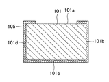
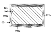
図5は、橋脚横梁の補強構造の従来例を説明するための側面図である。図示のものでは、橋脚横梁101の上面101aには、支承102や落橋防止装置103等(以下、“干渉物”と称する)が配置されているので、横梁101の全周に強化繊維シートを巻き付けることは出来ない。そこで、図6に詳示するように、それらの干渉物を避けるように強化繊維シート105を横梁側面101b,101d及び横梁下面101cに略U字状に貼り付けることとし(以下、この強化繊維シート105を“U字型繊維シート”と称する)、該干渉物と干渉しない部分においては、図7に詳示するように、該U字型繊維シート105の上から別の強化繊維シート106を巻き付けるようにしている。
しかしながら、橋脚横梁においては、側面にも鋼製ブラケットなどの干渉物が取り付けられている場合もあり、そのような横梁においては上述の補強構造は活用できないという問題があった。 However, in the bridge pier horizontal beam, there is a case where an interference object such as a steel bracket is also attached to the side surface, and there is a problem that the above-described reinforcing structure cannot be used in such a horizontal beam.
本発明は、上述のような問題を解決する橋脚横梁の補強構造を提供することを目的とするものである。 The object of the present invention is to provide a reinforcing structure for a bridge pier cross beam that solves the above-described problems.
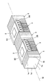
請求項1に係る発明は、図1乃至図3に例示するものであって、上面(1a)に支承(2)が配置され、一の側面(1b)に一の鋼製ブラケット(3B)が取り付けられ、他の側面(1d)に他の鋼製ブラケット(3D)が取り付けられてなる略矩形状断面の橋脚横梁(1)の補強構造において、
平面視において前記2つの鋼製ブラケット(3B,3D)が前記支承(2)を挟み込むような位置関係となるように、それらが配置され、
前記一の側面(1b)の一部であって前記一の鋼製ブラケット(3B)の下方に位置する一の側面部分、前記横梁(1)の下面(1c)の一部であって前記一の側面部分に連続するところの下面部分、及び前記他の側面(1d)の一部であって前記他の鋼製ブラケット(3D)の下方に位置する他の側面部分に亘ってU字状に貼付される第1強化繊維シート(5)と、
前記横梁(1)の上面(1a)における前記支承(2)が配置されていない部分、前記一の側面(1b)における前記一の鋼製ブラケット(3B)が取り付けられていない部分、前記横梁(1)の下面(1c)、及び前記他の側面(1d)における前記他の鋼製ブラケット(3D)が取り付けられていない部分に亘って横梁全周に帯状に巻き付けられる第2強化繊維シート(6)と、を備えたことを特徴とする。
The invention according to
They are arranged so that the two steel brackets (3B, 3D) are in a positional relationship so as to sandwich the support (2) in plan view,
A part of the one side surface (1b) and located below the one steel bracket (3B), a part of the lower surface (1c) of the transverse beam (1), and the one side surface In a U-shape over a lower surface portion continuous with the side surface portion and another side surface portion that is a part of the other side surface (1d) and is located below the other steel bracket (3D). A first reinforcing fiber sheet (5) to be affixed;
A portion of the upper surface (1a) of the transverse beam (1) where the support (2) is not disposed, a portion of the one side surface (1b) where the one steel bracket (3B) is not attached, 2) a second reinforcing fiber sheet (6) wound around the entire circumference of the transverse beam over the lower surface (1c) of 1) and the other side surface (1d) where the other steel bracket (3D) is not attached. ).
請求項2に係る発明は、図4に例示するものであって、上面(1a)に支承(2)が配置され、一の側面(1b)に一の鋼製ブラケット(3B)が取り付けられ、他の側面(1d)に他の鋼製ブラケット(3D)が取り付けられてなる略矩形状断面の橋脚横梁(1)の補強構造において、
前記一の鋼製ブラケット(3B)と前記他の鋼製ブラケット(3D)とは、平面視において、前記橋脚横梁(1)の長手方向中心軸(M)を挟むように対称に配置され、
前記支承(2)は、平面視において前記2つの鋼製ブラケット(3B,3D)に挟み込まれない位置に配置され、
前記一の側面(1b)の一部であって前記一の鋼製ブラケット(3B)の下方に位置する一の側面部分、前記横梁(1)の下面(1c)の一部であって前記一の側面部分に連続するところの下面部分、及び前記他の側面(1d)の一部であって前記他の鋼製ブラケット(3D)の下方に位置する他の側面部分に亘ってU字状に貼付される第1強化繊維シート(5)と、
前記横梁(1)の上面(1a)の一部であって前記支承(2)と前記一の側面(1b)との間の上面部分(1a1)、前記一の側面(1b)の一部であって前記上面部分(1a1)に連続するところの一の側面部分、前記横梁(1)の下面(1c)の一部であって前記一の側面部分に連続するところの下面部分、前記他の側面(1d)の一部であって前記下面部分に連続するところの他の側面部分、及び、前記横梁(1)の上面(1a)の一部であって前記他の側面部分に連続するところの上面部分(1a2)に亘って貼付される第3強化繊維シート(8)と、を備えたことを特徴とする。
The invention according to
The one steel bracket (3B) and the other steel bracket (3D) are arranged symmetrically so as to sandwich the longitudinal center axis (M) of the bridge pier transverse beam (1) in plan view,
The support (2) is arranged at a position where it is not sandwiched between the two steel brackets (3B, 3D) in plan view,
A part of the one side surface (1b) and located below the one steel bracket (3B), a part of the lower surface (1c) of the transverse beam (1), and the one side surface In a U-shape over a lower surface portion continuous with the side surface portion and another side surface portion that is a part of the other side surface (1d) and is located below the other steel bracket (3D). A first reinforcing fiber sheet (5) to be affixed;
Top portion (1a 1), said portion of one side surface (1b) between the crossbeam (1) of the upper surface (1a) wherein a portion bearing (2) and the aspect of (1b) A side surface portion continuous with the upper surface portion (1a 1 ), a lower surface portion which is a part of the lower surface (1c) of the transverse beam (1) and is continuous with the one side surface portion, Another side surface part that is a part of the other side surface (1d) and continuous with the lower surface part, and a part of the upper surface (1a) of the cross beam (1) that is continuous with the other side surface part. And a third reinforcing fiber sheet (8) attached over the upper surface portion (1a 2 ).
請求項3に係る発明は、請求項2に係る発明において、前記横梁(1)の上面(1a)における前記支承(2)が配置されていない部分、前記一の側面(1b)における前記一の鋼製ブラケット(3B)が取り付けられていない部分、前記横梁(1)の下面(1c)、及び前記他の側面(1d)における前記他の鋼製ブラケット(3D)が取り付けられていない部分に亘って横梁(1)全周に帯状に巻き付けられる第2強化繊維シート(6)、を備えたことを特徴とする。
The invention according to claim 3 is the invention according to
請求項4に係る発明は、請求項2又は3に係る発明において、前記第3強化繊維シート(8)の一部であって前記横梁(1)の上面部分(1a1,1a2)に貼り付けられた部分、及び前記横梁(1)の上面(1a)の一部であって前記第3強化繊維シート(8)が貼り付けられていない部分の両方に亘って貼付される第4強化繊維シート(9)、を備えたことを特徴とする。 The invention according to a fourth aspect is the invention according to the second or third aspect, wherein it is a part of the third reinforcing fiber sheet (8) and is affixed to the upper surface portion (1a 1 , 1a 2 ) of the transverse beam (1). The fourth reinforcing fiber to be applied over both the attached part and the part of the upper surface (1a) of the transverse beam (1) to which the third reinforcing fiber sheet (8) is not attached. A sheet (9) is provided.
請求項5に係る発明は、請求項1乃至4のいずれか1項に記載の発明において、前記第1強化繊維シート(5)の上端部分を前記横梁(1)の方に付勢する付勢部材(図3及び図4の符号7参照)、を備えたことを特徴とする。
The invention according to
請求項6に係る発明は、請求項5に記載の発明において、前記付勢部材が、前記第1強化繊維シート(5)の幅方向両外側に突出するように配置されると共に、該第1強化繊維シート(5)の上端部分及び横梁表面(1b,1c)に亘って貼付された第5強化繊維シート(不図示)であることを特徴とする。
The invention according to
請求項7に係る発明は、請求項5に係る発明において、前記付勢部材(7)は鋼製部材であって固定部材(不図示)を介して前記横梁(1)又は前記鋼製ブラケット(3B,3D)に固定されたことを特徴とする。
The invention according to
請求項8に係る発明は、請求項1,3及び4のいずれか1項に記載の発明において、前記第1強化繊維シート(5)の上端部分を前記横梁(1)の方に付勢する付勢部材(7)、
を備え、
該付勢部材(7)は、前記第1強化繊維シート(5)の表面に当接すると共に該第1強化繊維シート(5)の幅方向両外側に突出するように配置され、
該突出した部分は、前記第2強化繊維シート(6)と前記横梁(1)との間に挟持された状態で固定されることを特徴とする。
The invention according to an eighth aspect is the invention according to any one of the first, third and fourth aspects, wherein the upper end portion of the first reinforcing fiber sheet (5) is urged toward the transverse beam (1). Biasing member (7),
With
The urging member (7) is disposed so as to abut on the surface of the first reinforcing fiber sheet (5) and protrude outward in the width direction of the first reinforcing fiber sheet (5).
The protruding portion is fixed in a state of being sandwiched between the second reinforcing fiber sheet (6) and the cross beam (1).
請求項9に係る発明は、請求項8に記載の発明において、前記付勢部材は鋼製部材又は第5強化繊維シートであることを特徴とする。
The invention according to
請求項10に係る発明は、請求項1乃至4のいずれか1項に記載の発明において、前記第1強化繊維シート(5)の上端部分に鋼製固定部材(不図示)が取り付けられ、
前記第1強化繊維シート(5)の上端部分は該鋼製固定部材(不図示)を介して前記鋼製ブラケット(3B,3D)に固定されたことを特徴とする。
The invention according to claim 10 is the invention according to any one of
The upper end portion of the first reinforcing fiber sheet (5) is fixed to the steel bracket (3B, 3D) via the steel fixing member (not shown).
請求項11に係る発明は、図8(b) に例示するものであって、一の側面(1b)に一の鋼製ブラケット(13B)が取り付けられ、他の側面(1d)に他の鋼製ブラケット(13D)が取り付けられてなる略矩形状断面の橋脚横梁(1)の補強構造において、
前記一の鋼製ブラケット(13B)と前記他の鋼製ブラケット(13D)とは、平面視において、前記橋脚横梁(1)の長手方向中心軸(図1等の符号M参照)を挟むように対称に配置され、
前記一の側面(1b)の一部であって前記一の鋼製ブラケット(13B)の下方に位置する一の側面部分、前記横梁の下面(1c)の一部であって前記一の側面部分に連続するところの下面部分、及び前記他の側面(1d)の一部であって前記他の鋼製ブラケット(13D)の下方に位置する他の側面部分に亘って第1強化繊維シート(15)が略U字状に貼付され、
該第1強化繊維シート(15)の上端部分は、板状部材(18)を挟み込んだ状態で折り曲げられ、
該折り曲げ部(15a)には、前記第1強化繊維シート(15)及び板状部材(18)を貫通する貫通孔(図9の符号15c参照)が形成され、
該折り曲げ部(15a)は、前記貫通孔(15c)に挿通された固定部材(16)を介して前記橋脚横梁(1)に固定されたことを特徴とする。
The invention according to claim 11 is illustrated in FIG. 8 (b), wherein one steel bracket (13B) is attached to one side surface (1b), and another steel is attached to the other side surface (1d). In the reinforcing structure of the bridge pier cross beam (1) having a substantially rectangular cross section to which the made bracket (13D) is attached,
The one steel bracket (13B) and the other steel bracket (13D) sandwich the longitudinal center axis (see reference numeral M in FIG. 1 and the like) of the pier lateral beam (1) in plan view. Placed symmetrically,
One side surface portion that is a part of the one side surface (1b) and is located below the one steel bracket (13B), and a part of the lower surface (1c) of the transverse beam that is the one side surface portion. The first reinforcing fiber sheet (15) over the lower surface portion that is continuous with the other side surface portion that is a part of the other side surface (1d) and is located below the other steel bracket (13D). ) Is affixed in a substantially U shape,
The upper end portion of the first reinforcing fiber sheet (15) is bent in a state of sandwiching the plate-like member (18),
In the bent portion (15a), a through hole (see
The bent portion (15a) is fixed to the pier lateral beam (1) through a fixing member (16) inserted through the through hole (15c).
請求項12に係る発明は、請求項11に係る発明において、前記鋼製ブラケット(13B,13D)は、前記橋脚横梁(1)の側面(1b,1d)に沿って配置された平板状の部材であり、
該平板状の鋼製ブラケット(13B,13D)と、該鋼製ブラケット(13B,13D)の下方に並設されることとなる前記折り曲げ部(15a)と、に亘って第1押え部材(図10(b) の符号20参照)を配置し、
これらの鋼製ブラケット(13B,13D)及び折り曲げ部(15a)が前記橋脚横梁(1)の側面(1b,1d)と前記第1押え部材(20)との間に挟持されるように、該第1押え部材(20)を第1押え用固定部材(16,17,21,22)にて前記側面(1b,1d)に固定したことを特徴とする。
The invention according to claim 12 is the invention according to claim 11, wherein the steel brackets (13B, 13D) are flat members arranged along the side surfaces (1b, 1d) of the bridge pier transverse beam (1). And
A first presser member (see FIG. 5) spans the flat steel brackets (13B, 13D) and the bent portion (15a) to be juxtaposed below the steel brackets (13B, 13D). 10 (b) (see symbol 20)),
The steel brackets (13B, 13D) and the bent portion (15a) are sandwiched between the side surfaces (1b, 1d) of the pier lateral beam (1) and the first pressing member (20). The first pressing member (20) is fixed to the side surface (1b, 1d) by a first pressing fixing member (16, 17, 21, 22).
請求項13に係る発明は、請求項11に係る発明において、前記鋼製ブラケットは、略水平な板状部材(図12の符号32参照)をその下端部分に有し、
該板状部材(32)の下面及び前記折り曲げ部(15a)の表面に沿うように配置された、断面が略L字形の第2押え部材(34)を有し、
該第2押え部材(34)が前記橋脚横梁(1)の側面(1b,1d)との間に前記折り曲げ部(15a)を挟持すると共に前記板状部材(32)に固定されるように、該第2押え部材(34)を第2押え用固定部材(36,37,38,39)にて前記側面(1b,1d)及び前記板状部材(32)に固定したことを特徴とする。
The invention according to claim 13 is the invention according to claim 11, wherein the steel bracket has a substantially horizontal plate-like member (see
A second presser member (34) having a substantially L-shaped cross section disposed along the lower surface of the plate-like member (32) and the surface of the bent portion (15a);
The second holding member (34) sandwiches the bent portion (15a) between the side surface (1b, 1d) of the bridge pier transverse beam (1) and is fixed to the plate-like member (32). The second pressing member (34) is fixed to the side surface (1b, 1d) and the plate-like member (32) by a second pressing fixing member (36, 37, 38, 39).
請求項14に係る発明は、略水平な板状部材(図13の符号32参照)を下端部分に有する一の鋼製ブラケット(3B)が前記一の側面(1b)に取り付けられ、略水平な板状部材(図11の符号32参照)を下端部分に有する他の鋼製ブラケット(3D)が前記他の側面(1d)に取り付けられてなる略矩形状断面の橋脚横梁(1)の補強構造において、
前記一の鋼製ブラケット(3B)と前記他の鋼製ブラケット(3D)とは、平面視において、前記橋脚横梁(1)の長手方向中心軸(M)を挟むように対称に配置され、
前記一の鋼製ブラケット(3B)の板状部材(32)の下面、前記一の側面(1b)の一部であって前記一の鋼製ブラケット(3B)の下方に位置する一の側面部分、前記横梁の下面(1c)の一部であって前記一の側面部分に連続するところの下面部分、前記他の側面(1d)の一部であって前記他の鋼製ブラケット(3D)の下方に位置する他の側面部分、及び前記他の鋼製ブラケット(3D)の板状部材の下面(1c)に亘って第6強化繊維シート(図13の符号35参照)が貼付され、
前記一の鋼製ブラケット(3B)の板状部材(32)の下面及び前記一の側面(1b)との間に前記第6強化繊維シート(35)を挟持するように、断面が略L字形の第2押え部材(34)を配置し、
前記他の鋼製ブラケット(3D)の板状部材(32)の下面及び前記他の側面(1d)との間に前記第6強化繊維シート(35)を挟持するように、断面が略L字形の第2押え部材(34)を配置し、
各第2押え部材(34)を第2押え用固定部材(36,37,38,39)によって各板状部材(32)及び各側面(1b,1d)に固定したことを特徴とする。
In the invention according to claim 14, one steel bracket (3B) having a substantially horizontal plate-like member (see
The one steel bracket (3B) and the other steel bracket (3D) are arranged symmetrically so as to sandwich the longitudinal center axis (M) of the bridge pier transverse beam (1) in plan view,
The lower surface of the plate-like member (32) of the one steel bracket (3B), one side surface portion that is a part of the one side surface (1b) and is located below the one steel bracket (3B). , A part of the lower surface (1c) of the transverse beam, the lower surface part that is continuous with the one side surface part, and a part of the other side surface (1d) of the other steel bracket (3D). A sixth reinforcing fiber sheet (see
The cross section is substantially L-shaped so that the sixth reinforcing fiber sheet (35) is sandwiched between the lower surface of the plate-like member (32) and the one side surface (1b) of the one steel bracket (3B). The second presser member (34) of
The cross section is substantially L-shaped so that the sixth reinforcing fiber sheet (35) is sandwiched between the lower surface of the plate-like member (32) and the other side surface (1d) of the other steel bracket (3D). The second presser member (34) of
Each second pressing member (34) is fixed to each plate-like member (32) and each side surface (1b, 1d) by a second pressing fixing member (36, 37, 38, 39).
請求項15に係る発明は、図8(a) に例示するものであって、一の側面(1b)に一の鋼製ブラケット(13B)が取り付けられ、他の側面(1d)に他の鋼製ブラケット(13D)が取り付けられてなる略矩形状断面の橋脚横梁(1)を補強する方法において、
2枚の強化繊維シート片(15B,15D)の上端部分(図9の符号15a参照)を、板状部材(18)を挟み込んだ状態に折り曲げる工程と、
その折り曲げ部(15a)以外に樹脂が含浸されないような状態で、該折り曲げ部(15a)に樹脂を含浸させる工程と、
該折り曲げ部(15a)にて前記板状部材(18)を貫通する貫通孔(15c)を穿設する工程と、
前記橋脚横梁(1)の側面(1b,1d)であって各鋼製ブラケット(13B,13D)の下方に、前記貫通孔(15c)を挿通させた固定部材(16)により各強化繊維シート片(15B,15D)を固定する工程と、
それら2つの強化繊維シート片(15B,15D)が前記橋脚横梁(1)の下面(1c)に回り込んで重なり合った状態で、それらのシート片(15B,15D)に樹脂を含浸させる工程と、を備えたことを特徴とする。
The invention according to
Bending the upper end portions of the two reinforcing fiber sheet pieces (15B, 15D) (see
A step of impregnating the bent portion (15a) with a resin in a state where the resin other than the bent portion (15a) is not impregnated;
Drilling a through hole (15c) penetrating the plate member (18) at the bent portion (15a);
Each reinforcing fiber sheet piece is provided by a fixing member (16) through which the through hole (15c) is inserted under the steel brackets (13B, 13D) on the side surfaces (1b, 1d) of the bridge pier horizontal beam (1). Fixing (15B, 15D);
A step of impregnating the sheet pieces (15B, 15D) with resin in a state in which the two reinforcing fiber sheet pieces (15B, 15D) wrap around and overlap the lower surface (1c) of the abutment cross beam (1); It is provided with.
なお、括弧内の番号などは、図面における対応する要素を示す便宜的なものであり、従って、本記述は図面上の記載に限定拘束されるものではない。 Note that the numbers in parentheses are for the sake of convenience indicating the corresponding elements in the drawings, and therefore the present description is not limited to the descriptions on the drawings.
請求項1乃至3に係る発明によれば、上面に支承が配置され、側面に鋼製ブラケットが取り付けられているような橋脚横梁であっても、強化繊維シートを貼り付けることによる十分な補強を行うことができる。
According to the inventions according to
請求項4に係る発明によれば、第3強化繊維シートの剥がれを抑制することができる。 According to the invention which concerns on Claim 4, peeling of a 3rd reinforcing fiber sheet can be suppressed.
請求項5乃至10に係る発明によれば、第1強化繊維シートの剥がれを抑制することができる。
According to the invention which concerns on
請求項11乃至14に係る発明によれば、側面に鋼製ブラケットが取り付けられているような橋脚横梁であっても、第1強化繊維シートを貼り付けることによって十分な補強を行なうことができる。また、該第1強化繊維シートの上端部分は、前記板状部材を配置した上で固定部材により橋脚横梁に固定されているので、該部分の横梁側面からの剥がれを防止することができる。 According to the invention which concerns on Claim 11 thru | or 14, sufficient reinforcement can be performed by sticking a 1st reinforcement fiber sheet, even if it is a bridge pier transverse beam with which steel brackets are attached to the side surface. Moreover, since the upper end portion of the first reinforcing fiber sheet is fixed to the bridge pier horizontal beam by the fixing member after the plate-like member is disposed, it is possible to prevent peeling of the portion from the side surface of the horizontal beam.
請求項15に係る発明によれば、強化繊維シート片の橋脚横梁への貼り付けは、各シート片の上端部(折り曲げ部)を橋脚横梁に固定部材で固定してから行なうため、各シート片の位置決めや保持が容易となり、そのような固定部材による固定を行なわない場合に比べ、後工程の作業(例えば、強化繊維シート片の未樹脂含浸部分に樹脂を含浸させる作業)を比較的簡単に行なうことができる。また、この方法によれば、強化繊維シート片の貼り付け長さ調整はその重なり部にて行なうことができ、それらのシート片をぴったりと橋脚横梁に貼付することができる。
According to the invention of
以下、図1乃至図4、及び図8乃至図13に沿って、本発明を実施するための最良の形態について説明する。ここで、図1は、本発明に係る橋脚横梁の補強構造の一例を示す斜視図であり、図2は、その橋脚横梁の全体構成の一例を示す側面図である。また、図3は、本発明に係る橋脚横梁の補強構造の他の例を示す斜視図であり、図4は、本発明に係る橋脚横梁の補強構造のさらに他の例を示す斜視図である。さらに、図8(a) は、本発明に係る橋脚横梁の補強方法の一例であって強化繊維シートを貼り付ける前の状態を示す断面図であり、図8(b) は、該強化繊維シートを貼り付けた後の状態を示す断面図である。また、図9は、第1強化繊維シートの構造の一例を示す断面図であり、図10(a)
は、本発明に係る橋脚横梁の補強方法の一例であって第1押え部材を配置する前の状態を示す断面図であり、図10(b) は、第1押え部材を配置した後の状態を示す断面図である。さらに、図11は、本発明に係る橋脚横梁の補強構造の一例を示す断面図であり、図12は、鋼製ブラケットへ強化繊維シートが固定される構造の一例を示す詳細断面図であり、図13は、鋼製ブラケットへ強化繊維シートが固定される構造の他の例を示す詳細断面図である。
(第1の形態)
The best mode for carrying out the present invention will be described below with reference to FIGS. 1 to 4 and FIGS. 8 to 13. Here, FIG. 1 is a perspective view showing an example of a reinforcement structure of a pier horizontal beam according to the present invention, and FIG. 2 is a side view showing an example of the entire structure of the pier horizontal beam. FIG. 3 is a perspective view showing another example of the reinforcement structure for a pier horizontal beam according to the present invention, and FIG. 4 is a perspective view showing still another example of the reinforcement structure for a bridge pier horizontal beam according to the present invention. . Further, FIG. 8 (a) is a cross-sectional view showing an example of the reinforcing method of a bridge pier cross beam according to the present invention and showing a state before the reinforcing fiber sheet is attached, and FIG. 8 (b) is the reinforcing fiber sheet. It is sectional drawing which shows the state after sticking. FIG. 9 is a cross-sectional view showing an example of the structure of the first reinforcing fiber sheet, and FIG.
Fig. 10 is an example of a method for reinforcing a bridge pier cross beam according to the present invention, and is a cross-sectional view showing a state before the first presser member is arranged, and Fig. 10 (b) is a state after the first presser member is arranged. FIG. Furthermore, FIG. 11 is a cross-sectional view showing an example of a reinforcement structure of a pier horizontal beam according to the present invention, FIG. 12 is a detailed cross-sectional view showing an example of a structure in which a reinforcing fiber sheet is fixed to a steel bracket, FIG. 13 is a detailed cross-sectional view showing another example of a structure in which a reinforcing fiber sheet is fixed to a steel bracket.
(First form)
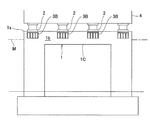
本発明が適用される橋脚横梁は、略矩形状断面であって、図2に例示するように、その上面1aには支承2が配置され、一の側面1bには鋼製ブラケット(以下、必要に応じて“一の鋼製ブラケット”と称する)3Bが取り付けられ、他の側面(図1の符号1d参照)には別の鋼製ブラケット(以下、必要に応じて“他の鋼製ブラケット”と称する)3Dが取り付けられている。そして、平面視において前記2つの鋼製ブラケット3B,3Dが前記支承2を挟み込むような位置関係となるように、それら(2つの鋼製ブラケット3B,3D及び支承2)が配置されている。なお、支承2は横梁1の長手方向中心軸Mに沿って複数配置されており、各支承2を挟み込むように鋼製ブラケット3B,3Dがそれぞれに配置されている。また、図2中の符号4は、橋梁上部工を示す。
The pier horizontal beam to which the present invention is applied has a substantially rectangular cross section, and as shown in FIG. 2, a
図1に示される橋脚横梁の補強構造は、
・ 符号5で示す第1強化繊維シートと、
・ 符号6で示す第2強化繊維シートと、
を備えている。このうち、第1強化繊維シート5は、
・ 前記一の側面1bの一部であって前記一の鋼製ブラケット3Bの下方に位置する一の側面部分、
・ 前記横梁1の下面1cの一部であって前記一の側面部分に連続するところの下面部分、
・ 前記他の側面1dの一部であって前記他の鋼製ブラケット3Dの下方に位置する他の側面部分
に亘ってU字状に貼付されている。また、第2強化繊維シート6は、
・ 前記横梁の上面1aにおける前記支承2が配置されていない部分、
・ 前記一の側面1bにおける前記一の鋼製ブラケット3Bが取り付けられていない部分、
・ 前記横梁の下面1c、
・ 前記他の側面1dにおける前記他の鋼製ブラケット3Dが取り付けられていない部分
に亘って横梁全周に帯状に巻き付けられている。本発明によれば、上面に支承2が配置され、側面に鋼製ブラケット3B,3Dが取り付けられているような橋脚横梁1であっても、強化繊維シート5,6を貼り付けることによる十分な補強を行うことができる。
The reinforcement structure of the pier cross beam shown in FIG.
A first reinforcing fiber sheet denoted by
A second reinforcing fiber sheet denoted by
It has. Of these, the first reinforcing
A side surface portion that is a part of the one
A lower surface portion that is a part of the
A part of the
A portion of the
A portion of the one
The
The belt is wound around the entire circumference of the transverse beam over a portion of the
ところで、このような補強構造においては、前記第1強化繊維シート5の上端部分(つまり、一の鋼製ブラケット3Bに近接する端縁部分、及び他の鋼製ブラケット3Dに近接する端縁部分の少なくとも一方、又は両方)の横梁側面からの剥がれを抑制するような構造にしておくと良い。そのための方法としては、前記第1強化繊維シート5の上端部分を前記横梁の方(つまり、横梁側面の方向)に付勢する付勢部材(図3の符号7参照)を配置すると良い。この場合、第1強化繊維シート5の上端部分を付勢するように付勢部材7を何らかの方法で支持しておく必要があるが、その方法としては、
・ アンカー部材やナット等のような固定部材を介して前記付勢部材7を前記横梁1や前記鋼製ブラケット3B,3D等に固定する方法
・ 該付勢部材を前記第1強化繊維シート5の表面に当接すると共に該シート5の幅方向両外側に突出するように配置しておき、該突出した部分を、前記第2強化繊維シート6と前記横梁1との間に挟持した状態で固定する方法
などを挙げることができる。この付勢部材としては鋼製の部材を挙げることができるが、後者の方法で固定する場合は強化繊維シート(第5強化繊維シート)を用いても良い。また、この第5強化繊維シートを後者の方法で固定するのではなく、第1強化繊維シート5の上端部分及び横梁表面に亘って貼付するようにしても良い。
By the way, in such a reinforcing structure, the upper end portion of the first reinforcing fiber sheet 5 (that is, the end portion close to one
A method of fixing the biasing
また、上述のような付勢部材を用いるのではなく、第1強化繊維シート5の上端部分に、形鋼などの鋼製固定部材(不図示)を取り付けておき、該鋼製固定部材を介して該上端部分を前記鋼製ブラケット3B,3Dに固定するようにしても良い。
(第2の形態)
Further, instead of using the urging member as described above, a steel fixing member (not shown) such as a shape steel is attached to the upper end portion of the first reinforcing
(Second form)
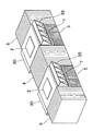
一方、図4に例示した橋脚横梁は、断面が略矩形状であって、上面には支承2が配置され、側面1b、1dには一の鋼製ブラケット3B及び他の鋼製ブラケット3Dがそれぞれ取り付けられているが、図1乃至図3と異なり、平面視において前記2つの鋼製ブラケット3B,3Dが前記支承2を挟み込むような位置関係となるようにはなっていない。前記一の鋼製ブラケット3Bと前記他の鋼製ブラケット3Dとは、平面視において、前記橋脚横梁の長手方向中心軸Mを挟むように対称に配置され、前記支承2は、平面視において前記2つの鋼製ブラケット3B,3Dに挟み込まれない位置に配置されている。
On the other hand, the cross section of the bridge pier illustrated in FIG. 4 has a substantially rectangular cross section, the
そして、図4に示される橋脚横梁の補強構造は、少なくとも、
・ 符号5で示す第1強化繊維シートと、
・ 符号8で示す第3強化繊維シートと、
を備えている。なお、図4では、第2強化繊維シート6も示されているが、該第2強化繊維シート6を有さない構造のものも権利範囲に含める趣旨である。
And the reinforcement structure of the pier cross beam shown in FIG.
A first reinforcing fiber sheet denoted by
A third reinforcing fiber sheet denoted by
It has. In addition, in FIG. 4, although the 2nd
ここで、第1強化繊維シート5及び第2強化繊維シート6は、第1の形態にて説明したと同様のものである。
Here, the first reinforcing
本発明によれば、上面に支承2が配置され、側面に鋼製ブラケット3B,3Dが取り付けられているような橋脚横梁1であっても、強化繊維シート5,6,8を貼り付けることによる十分な補強を行うことができる。
According to the present invention, the reinforcing
なお、第1強化繊維シート5の上端部分については、第1の形態のものと同様の方法で剥がれ抑制対策を行っても良い。すなわち、
・ 該上端部分を付勢部材7によって付勢するようにしても、
・ 鋼製固定部材を介して鋼製ブラケットに固定するようにしても、
良い。また、付勢部材7の支持は、
・ アンカー部材やナット等のような固定部材を介して前記付勢部材7を前記横梁1や前記鋼製ブラケット3B,3D等に固定する方法
・ 該付勢部材を前記第1強化繊維シート5の表面に当接すると共に該シート5の幅方向両外側に突出するように配置しておき、該突出した部分を、前記第2強化繊維シート6と前記横梁1との間に挟持した状態で固定する方法
などにより行えば良い。
In addition, about the upper end part of the 1st
-Even if the upper end portion is urged by the urging
・ Even if it is fixed to a steel bracket via a steel fixing member,
good. The support of the biasing
A method of fixing the biasing
また、図4に示す補強構造のものでは、支承2の幅寸法D1が横梁1の幅寸法D2よりも小さく、該支承2の両側に横梁1の上面1aの一部(支承2と前記一の側面1bとの間の上面部分1a1、及び支承2と前記他の側面1dとの間の上面部分1a2である。)が露出されるように(言い換えれば、支承2にて覆われないように)構成されている。そして、第3強化繊維シート8は、
・ 一方の上面部分1a1、
・ 前記一の側面1bの一部であって前記上面部分1a1に連続するところの一の側面部分、
・ 前記横梁の下面1cの一部であって前記一の側面部分に連続するところの下面部分、
・ 前記他の側面1dの一部であって前記下面部分に連続するところの他の側面部分、
・ 他方の上面部分1a2、
に亘って貼付されている。
In the reinforcing structure shown in FIG. 4, the width D 1 of the
One
One side surface portion which is a part of the one
A lower surface portion that is a part of the
The other side surface portion that is a part of the
The other
It is pasted over.
この場合、前記第3強化繊維シート8の一部(具体的には、前記横梁の上面部分1a1,1a2に貼り付けられた部分)、及び前記横梁の上面1aの一部(しかも、前記第3強化繊維シート8が貼り付けられていない部分)の両方に亘って第4強化繊維シート9を貼付するようにしても良い。これにより、第3強化繊維シート8の剥がれを抑制することができる。なお、図示の第4強化繊維シート9は、横梁の長手方向全体に亘って配置されているが、もちろんこれに限られるものではなく、図示のものよりも短くても良い。
In this case, a part of the third reinforcing fiber sheet 8 (specifically, a part attached to the
上述の各強化繊維シート5,6,8は、約90度に折り曲げられて配置されるが、その折り曲げ部分を予め部分的にプレキャストシートに形成しておくと良い。例えば、上述の第3強化繊維シート8の端部(90度だけ内側に折り曲げられた部分)をプレキャストシートとしておくと、横梁上方に十分な作業空間を確保できない場合であっても比較的簡単に作業を行うことができる。
(第3の形態)
Each of the above-mentioned reinforcing
(Third form)
次に、図8乃至図10に沿って、本発明の第3の形態について説明する。 Next, a third embodiment of the present invention will be described with reference to FIGS.
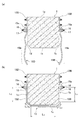
この第3の形態が適用される橋脚横梁は、図8(a) に示すように、略矩形状断面であって、一の側面1bには鋼製ブラケット(以下、必要に応じて“一の鋼製ブラケット”と称する)13Bが取り付けられ、他の側面1dには別の鋼製ブラケット(以下、必要に応じて“他の鋼製ブラケット”と称する)13Dが取り付けられている。この一の鋼製ブラケット13Bと他の鋼製ブラケット13Dとは、平面視において、前記橋脚横梁の長手方向中心軸(図1の符号M参照)を挟むように対称に配置されている。
As shown in FIG. 8 (a), the bridge pier horizontal beam to which the third embodiment is applied has a substantially rectangular cross section, and one
本形態に係る橋脚横梁の補強構造は、図8(b) に符号15で示す第1強化繊維シートを備えている。この第1強化繊維シート15は、
・ 前記一の側面1bの一部であって前記一の鋼製ブラケット13Bの下方に位置する一の側面部分、
・ 前記横梁1の下面1cの一部であって前記一の側面部分に連続するところの下面部分、
・ 前記他の側面1dの一部であって前記他の鋼製ブラケット13Dの下方に位置する他の側面部分
に亘って略U字状に貼付されている。この第1強化繊維シート15の上端部分(図9に符号15aで示す部分であって、一の鋼製ブラケット13Bに近接する端縁部分、及び他の鋼製ブラケット13Dに近接する端縁部分の少なくとも一方、又は両方)は、板状部材18を挟み込んだ状態で折り曲げられており、該折り曲げ部15aには、前記第1強化繊維シート15及び板状部材18を貫通する貫通孔15cが形成されている。そして、この折り曲げ部15aは、前記貫通孔15cに挿通された固定部材(例えば、符号16で示すボルトや、符号17で示すナット等)を介して橋脚横梁1に固定されている。この折り曲げ部15a等には樹脂が含浸されている(詳細は後述する)。
The reinforcing structure of a bridge pier horizontal beam according to this embodiment includes a first reinforcing fiber sheet indicated by
One side surface portion that is a part of the one
A lower surface portion that is a part of the
A part of the
この構造によれば、側面に鋼製ブラケット13B,13Dが取り付けられているような橋脚横梁1であっても、第1強化繊維シート15を貼り付けることによって十分な補強を行なうことができる。また、該第1強化繊維シート15の上端部分は、前記板状部材18を上述のように配置した上で固定部材16,17により橋脚横梁1に固定されているので、該部分の横梁側面からの剥がれを防止することができる。
According to this structure, sufficient reinforcement can be performed by affixing the first reinforcing
ところで、橋脚横梁1の補強のためには、上述の第1強化繊維シート15が、一方のボルト16から他方のボルト16までの部分(符号L1,L2,L3,L4,L5に示す部分であって、横梁表面部分)にぴったりと貼り付けることが必要である。そのための一つの方法としては、前記第1強化繊維シート15を、上部に前記折り曲げ部15aを有する2つの強化繊維シート片15B,15Dに分割しておき(図8(a) 参照)、各強化繊維シート片15B,15Dの折り曲げ部15aをボルト16にて橋脚横梁1の側面に固定し(図8(a) 参照)、それら2つの強化繊維シート片15B,15Dを橋脚横梁1の下面1cにて重ね合わせるようにして貼付すると良い(図8(b)
参照)。この方法によれば、強化繊維シート片15B,15Dの橋脚横梁1への貼り付けは、各シート片15B,15Dの上端部(折り曲げ部15a)を橋脚横梁1にボルト16で固定してから行なうため、各シート片15B,15Dの位置決めや保持が容易となり、そのようなボルト16による固定を行なわない場合に比べ、後工程の作業(例えば、強化繊維シート片15B,15Dの符号15bの部分に樹脂を含浸させる作業)を比較的簡単に行なうことができる。また、この方法によれば、強化繊維シート片15B,15Dの貼り付け長さ調整はその重なり部にて行なうことができ、それらのシート片15B,15Dをぴったりと橋脚横梁1に貼付することができる。
By the way, in order to reinforce the bridge
reference). According to this method, the reinforcing
しかしながら、第1強化繊維シート15は、上述の強化繊維シート片15B,15Dに2分割しただけのものに限定されるものでは無く、必要に応じて3つ以上に分割するようにしても良い。また、上述の貼り付け長さ調整を別の方法(つまり、2つの強化繊維シート片15B,15Dの重なり代を調整するという方法以外の方法)で行なうようにした場合には、第1強化繊維シート15を分割せずに一体物(つまり、両端部にそれぞれ折り曲げ部15aを形成した構造のもの)にしても良い。
However, the first reinforcing
ところで、2つの強化繊維シート片15B,15Dに分割された前記第1強化繊維シート15による橋脚横梁1の補強方法は以下の手順で行なうと良い。すなわち、
(1) 2枚の強化繊維シート片15B,15Dの上端部分を、前記板状部材18を挟み込んだ状態に折り曲げる工程
(2) その折り曲げ部以外15bに樹脂が含浸されないような状態で、該折り曲げ部15aに樹脂を含浸させる工程
(3) 樹脂が固まった段階で、前記板状部材18を貫通する貫通孔15cを該折り曲げ部15aに穿設する工程
(4) 図8(a) に示すように、前記貫通孔15cを挿通された固定部材16により、前記橋脚横梁1の側面1b,1dであって各鋼製ブラケット13B,13Dの下方に各強化繊維シート片15B,15Dを固定する工程
(5) 図8(b) に示すように、それら2つの強化繊維シート片15B,15Dが前記橋脚横梁1の下面1cに回り込んで重なり合った状態で、それらのシート片15B,15Dに樹脂を含浸させる工程
By the way, the reinforcing method of the pier
(1) A step of bending the upper end portions of the two reinforcing
(2) A step of impregnating the
(3) A step of drilling a through
(4) As shown in FIG. 8 (a), by the fixing
(5) As shown in FIG. 8 (b), in the state in which the two reinforcing
ところで、図示の鋼製ブラケット13B,13Dは、前記橋脚横梁の側面1b、1dに沿って配置された平板状の部材であって、上述した折り曲げ部15aはこの平板状鋼製ブラケット13B,13Dの下方に1つずつ並設されることとなる(図10(a) 参照)。そこで、これらの鋼製ブラケット13B,13Dと各折り曲げ部15aとに亘って第1押え部材20をそれぞれ配置し、これらの鋼製ブラケット13B,13Dと各折り曲げ部15aとが前記橋脚横梁1の側面1b,1dと前記第1押え部材20との間に挟持されるように、該第1押え部材20を第1押え用固定部材16,17,21,22にて固定すると良い。なお、図10(a)
(b) に示す符号21は、鋼製ブラケット側に取り付けられたボルトを示し、符号22は該ボルト21に螺合されるナットを示し、符号16は、折り曲げ部15aの貫通孔15cを貫通した状態で橋脚横梁1に埋設されたボルトを示し、符号17は、該ボルト16に螺合されたナットを示す。また、図10(a)
の符号23は、高さを揃えるために配置されたスペーサとしてのナットを示す。
(第4の形態)
Incidentally, the
(4th form)
次に、図11及び図12に沿って、本発明の第4の形態について説明する。 Next, the 4th form of this invention is demonstrated along FIG.11 and FIG.12.
この第4の形態においては、図11に示すように、略矩形状断面の橋脚横梁1の一の側面1bには鋼製ブラケット(以下、必要に応じて“一の鋼製ブラケット”と称する)3Bが取り付けられ、他の側面1dには別の鋼製ブラケット(以下、必要に応じて“他の鋼製ブラケット”と称する)3Dが取り付けられている。これらの鋼製ブラケット3B,3Dは、図1等に示した鋼製ブラケットと同様の形状をしている。すなわち、橋脚横梁1の表面に沿うように配置された平板30と、略水平な上板31及び下板32とを有しており、それらの上板31と下板32との間には平板30に略垂直な部材(垂直板)33が複数並設されている。
In the fourth embodiment, as shown in FIG. 11, a steel bracket (hereinafter referred to as “one steel bracket” if necessary) is provided on one
そして、本形態に係る橋脚横梁の補強構造は、第3の形態と同様の構造の第1強化繊維シート15を備えている。すなわち、この第1強化繊維シート15は、
・ 前記一の側面1bの一部であって前記一の鋼製ブラケット3Bの下方に位置する一の側面部分、
・ 前記横梁1の下面1cの一部であって前記一の側面部分に連続するところの下面部分、
・ 前記他の側面1dの一部であって前記他の鋼製ブラケット3Dの下方に位置する他の側面部分
に亘って略U字状に貼付されている。この第1強化繊維シート15の上端部分(図9に符号15aで示す部分であって、一の鋼製ブラケット3Bに近接する端縁部分、及び他の鋼製ブラケット3Dに近接する端縁部分の少なくとも一方、又は両方)は、板状部材18を挟み込むように折り曲げられており、該折り曲げ部15aには、前記第1強化繊維シート15及び板状部材18を貫通する貫通孔15cが2つ形成されている(図9には1つのみ示す)。
And the reinforcement structure of the bridge pier horizontal beam which concerns on this form is provided with the 1st
A side surface portion that is a part of the one
A lower surface portion that is a part of the
A part of the
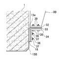
上述の鋼製ブラケット3Bの下板32の下面には中間板材33が配置されており、その下面及び前記折り曲げ部15aの表面に沿うように、断面が略L字状の第2押え部材34が配置されている。そして、該第2押え部材34が前記橋脚横梁1の側面1bとの間に前記折り曲げ部15aを挟持すると共に前記板状部材32に固定されるように、該第2押え部材34を第2押え用固定部材(例えば、符号36,38で示すボルトや、符号37,39で示すナット)にて前記側面及び前記板状部材32に固定している。なお、2本のボルト36は、上述の2つの貫通孔15cに挿通されている。他方の鋼製ブラケット3Dについても同様の構造で第1強化繊維シート15を固定すると良い。ところで、上述の第2押え部材34による固定は、下端部分に略水平な板状部材を有している鋼製ブラケットであれば可能であって、図11に示す構造の鋼製ブラケット3B,3D(つまり、平板30や上板31や垂直板33を有する構造のブラケット)に限定されるものでは無い。
An
次に、橋脚を補強する方法について説明する。
(1) 第3の形態と同様の方法で、図9に示す強化繊維シート片15B,15Dを作製する。すなわち、まず、2枚の強化繊維シート片15B,15Dの上端部分を、前記板状部材18を挟み込んだ状態に折り曲げ、その折り曲げ部以外15bに樹脂が含浸されないような状態で、該折り曲げ部15aに樹脂を含浸させ、樹脂が固まった段階で、前記板状部材18を貫通する貫通孔15cを該折り曲げ部15aに穿設する。
(2) 次に、各折り曲げ部15aを、上述の第2押え部材34や第2押え用固定部材36,37,38,39により図12に示すように固定する。このとき、折り曲げ部以外の部分15bは含浸されていないので、垂れ下がった状態となる。
(3) 図11に示すように、それら2つの強化繊維シート片15B,15Dが前記橋脚横梁1の下面1cに回り込んで重なり合った状態で、それらのシート片15B,15Dに樹脂を含浸させる。
(第5の形態)
Next, a method for reinforcing the pier will be described.
(1) Reinforcing
(2) Next, each bending
(3) As shown in FIG. 11, in a state where these two reinforcing
(5th form)
次に、図13に沿って、本発明の第5の形態について説明する。 Next, a fifth embodiment of the present invention will be described with reference to FIG.
本形態においては、鋼製ブラケットは第4の形態と同様の構造であって、同様の位置に配置されているので、該鋼製ブラケット3B,3Dについての重複説明は省略する。なお、第3の形態においても述べたように、鋼製ブラケットは、下端部分に略水平な板状部材を有している鋼製ブラケットであれば十分であり、図11に示す構造の鋼製ブラケット3B,3D(つまり、平板30や上板31や垂直板33を有する構造のブラケット)に限定されるものでは無い。
In the present embodiment, the steel bracket has the same structure as that of the fourth embodiment and is disposed at the same position, and therefore, the duplicate description of the
そして、強化繊維シート(第6強化繊維シート)35が、
・ 前記一の鋼製ブラケット3Bの板状部材32の下面、
・ 前記一の側面1bの一部であって前記一の鋼製ブラケット3Bの下方に位置する一の側面部分、
・ 前記横梁1の下面1cの一部であって前記一の側面部分に連続するところの下面部分、
・ 前記他の側面1dの一部であって前記他の鋼製ブラケット3Dの下方に位置する他の側面部分
・ 前記他の鋼製ブラケット3Dの板状部材32の下面
に亘って略U字状に貼付されている。なお、この第6強化繊維シート35には、上述の折り曲げ部15aに相当する部分は形成されていない。そして、前記一の鋼製ブラケット3Bの板状部材32の下面及び前記一の側面部分に前記第6強化繊維シート35を押え付けるように、断面が略L字形の第2押え部材34を配置し、該第2押え部材34を第2押え用固定部材(例えば、符号36,38で示すボルトや、符号37,39で示すナット)によって固定した。また、前記他の鋼製ブラケット3Dの側も同様とし(不図示)、板状部材32の下面及び前記一の側面部分に前記第6強化繊維シート35を押え付けるように、断面が略L字形の第2押え部材34を配置し、該第2押え部材34を第2押え用固定部材(例えば、符号36,38で示すボルトや、符号37,39で示すナット)によって固定した。
The reinforcing fiber sheet (sixth reinforcing fiber sheet) 35 is
A lower surface of the plate-
A side surface portion that is a part of the one
A lower surface portion that is a part of the
-Another side surface part that is a part of the
1 橋脚横梁
1a 上面
1b 一の側面
1c 下面
1d 他の側面
2 支承
3B 一の鋼製ブラケット
3D 他の鋼製ブラケット
5 第1強化繊維シート
6 第2強化繊維シート
7 付勢部材
8 第3強化繊維シート
9 第4強化繊維シート
13B 一の鋼製ブラケット
13D 他の鋼製ブラケット
15 第1強化繊維シート
15B 強化繊維シート片
15D 強化繊維シート片
15a 折り曲げ部
15c 貫通孔
16 固定部材(第1押え用固定部材)
17 ナット(第1押え用固定部材)
18 板状部材
20 第1押え部材
21 ボルト(第1押え用固定部材)
22 ナット(第1押え用固定部材)
32 板状部材
34 第2押え部材
35 第6強化繊維シート
36 ボルト(第2押え用固定部材)
37 ナット(第2押え用固定部材)
38 ボルト(第2押え用固定部材)
39 ナット(第2押え用固定部材)
M 長手方向中心軸
DESCRIPTION OF
17 Nut (Fixing member for first presser)
18 Plate-shaped
22 Nut (fixing member for first presser)
32 Plate-shaped
37 Nut (2nd presser fixing member)
38 bolts (second presser fixing member)
39 Nut (2nd presser fixing member)
M Longitudinal central axis
Claims (15)
平面視において前記2つの鋼製ブラケットが前記支承を挟み込むような位置関係となるように、それらが配置され、
前記一の側面の一部であって前記一の鋼製ブラケットの下方に位置する一の側面部分、前記横梁の下面の一部であって前記一の側面部分に連続するところの下面部分、及び前記他の側面の一部であって前記他の鋼製ブラケットの下方に位置する他の側面部分に亘ってU字状に貼付される第1強化繊維シートと、
前記横梁の上面における前記支承が配置されていない部分、前記一の側面における前記一の鋼製ブラケットが取り付けられていない部分、前記横梁の下面、及び前記他の側面における前記他の鋼製ブラケットが取り付けられていない部分に亘って横梁全周に帯状に巻き付けられる第2強化繊維シートと、
を備えたことを特徴とする橋脚横梁の補強構造。 In the reinforcement structure of a bridge pier cross beam having a substantially rectangular cross section in which a support is arranged on the upper surface, one steel bracket is attached to one side, and another steel bracket is attached to the other side.
They are arranged so that the two steel brackets are in a positional relationship so as to sandwich the support in plan view,
A part of the one side surface and located below the one steel bracket; a lower surface part of the lower surface of the transverse beam that is continuous with the one side part; and A first reinforcing fiber sheet that is a part of the other side surface and is affixed in a U-shape over the other side surface portion located below the other steel bracket;
A portion where the support is not disposed on the upper surface of the cross beam, a portion where the one steel bracket is not attached on the one side surface, a lower surface of the cross beam, and the other steel bracket on the other side surface. A second reinforcing fiber sheet that is wound in a belt shape around the entire circumference of the cross beam over the portion that is not attached;
Reinforced structure of pier cross beam characterized by comprising
前記一の鋼製ブラケットと前記他の鋼製ブラケットとは、平面視において、前記橋脚横梁の長手方向中心軸を挟むように対称に配置され、
前記支承は、平面視において前記2つの鋼製ブラケットに挟み込まれない位置に配置され、
前記一の側面の一部であって前記一の鋼製ブラケットの下方に位置する一の側面部分、前記横梁の下面の一部であって前記一の側面部分に連続するところの下面部分、及び前記他の側面の一部であって前記他の鋼製ブラケットの下方に位置する他の側面部分に亘ってU字状に貼付される第1強化繊維シートと、
前記横梁の上面の一部であって前記支承と前記一の側面との間の上面部分、前記一の側面の一部であって前記上面部分に連続するところの一の側面部分、前記横梁の下面の一部であって前記一の側面部分に連続するところの下面部分、前記他の側面の一部であって前記下面部分に連続するところの他の側面部分、及び、前記横梁の上面の一部であって前記他の側面部分に連続するところの上面部分に亘って貼付される第3強化繊維シートと、
を備えたことを特徴とする橋脚横梁の補強構造。 In the reinforcement structure of a bridge pier cross beam having a substantially rectangular cross section in which a support is arranged on the upper surface, one steel bracket is attached to one side, and another steel bracket is attached to the other side.
The one steel bracket and the other steel bracket are arranged symmetrically in a plan view so as to sandwich the longitudinal center axis of the bridge pier transverse beam,
The support is disposed at a position where it is not sandwiched between the two steel brackets in plan view,
A part of the one side surface and located below the one steel bracket; a lower surface part of the lower surface of the transverse beam that is continuous with the one side part; and A first reinforcing fiber sheet that is a part of the other side surface and is affixed in a U-shape over the other side surface portion located below the other steel bracket;
A part of the upper surface of the transverse beam, the upper surface part between the support and the one side surface, a side part of the one side surface that is continuous with the upper surface part, A lower surface portion that is a part of the lower surface and is continuous with the one side surface portion, another side surface portion that is a part of the other side surface and is continuous with the lower surface portion, and an upper surface of the transverse beam. A third reinforcing fiber sheet that is a part and is affixed over an upper surface portion that is continuous with the other side surface portion;
Reinforced structure of pier cross beam characterized by comprising
を備えたことを特徴とする請求項2に記載の橋脚横梁の補強構造。 A portion where the support is not disposed on the upper surface of the cross beam, a portion where the one steel bracket is not attached on the one side surface, a lower surface of the cross beam, and the other steel bracket on the other side surface. A second reinforcing fiber sheet that is wound in a belt-like manner around the entire circumference of the cross beam over the part that is not attached;
The reinforcing structure for a pier cross beam according to claim 2, comprising:
を備えたことを特徴とする請求項2又は3に記載の橋脚横梁の補強構造。 Both a part of the third reinforcing fiber sheet and affixed to the upper surface portion of the transverse beam, and a part of the upper surface of the transverse beam and the third reinforcing fiber sheet not affixed A fourth reinforcing fiber sheet to be applied over
The reinforcement structure of a pier cross beam according to claim 2 or 3, characterized by comprising:
を備えた請求項1乃至4のいずれか1項に記載の橋脚横梁の補強構造。 An urging member for urging the upper end portion of the first reinforcing fiber sheet toward the transverse beam;
The reinforcement structure of the pier cross beam of any one of Claims 1 thru | or 4 provided with these.
ことを特徴とする請求項5に記載の橋脚横梁の補強構造。 The urging member is disposed so as to protrude outward in the width direction of the first reinforcing fiber sheet, and is attached to the upper end portion of the first reinforcing fiber sheet and the surface of the transverse beam. Is,
The reinforcement structure of a bridge pier transverse beam according to claim 5.
ことを特徴とする請求項5に記載の橋脚横梁の補強構造。 The biasing member is a steel member and fixed to the cross beam or the steel bracket via a fixing member,
The reinforcement structure of a bridge pier transverse beam according to claim 5.
該付勢部材は、前記第1強化繊維シートの表面に当接すると共に該第1強化繊維シートの幅方向両外側に突出するように配置され、
該突出した部分は、前記第2強化繊維シートと前記横梁との間に挟持された状態で固定される、
ことを特徴とする請求項1,3及び4のいずれか1項に記載の橋脚横梁の補強構造。 A biasing member that biases the upper end portion of the first reinforcing fiber sheet toward the transverse beam,
The urging member is disposed so as to abut on the surface of the first reinforcing fiber sheet and to protrude outward in the width direction of the first reinforcing fiber sheet,
The protruding portion is fixed in a state of being sandwiched between the second reinforcing fiber sheet and the cross beam.
The reinforcement structure of a bridge pier transverse beam according to any one of claims 1, 3 and 4.
ことを特徴とする請求項8に記載の橋脚横梁の補強構造。 The biasing member is a steel member or a fifth reinforcing fiber sheet.
The reinforcing structure of a bridge pier transverse beam according to claim 8.
前記第1強化繊維シートの上端部分は該鋼製固定部材を介して前記鋼製ブラケットに固定された、
ことを特徴とする請求項1乃至4のいずれか1項に記載の橋脚横梁の補強構造。 A steel fixing member is attached to the upper end portion of the first reinforcing fiber sheet,
The upper end portion of the first reinforcing fiber sheet was fixed to the steel bracket via the steel fixing member,
The reinforcement structure of a bridge pier cross beam according to any one of claims 1 to 4.
前記一の鋼製ブラケットと前記他の鋼製ブラケットとは、平面視において、前記橋脚横梁の長手方向中心軸を挟むように対称に配置され、
前記一の側面の一部であって前記一の鋼製ブラケットの下方に位置する一の側面部分、前記横梁の下面の一部であって前記一の側面部分に連続するところの下面部分、及び前記他の側面の一部であって前記他の鋼製ブラケットの下方に位置する他の側面部分に亘って第1強化繊維シートが略U字状に貼付され、
該第1強化繊維シートの上端部分は、板状部材を挟み込んだ状態で折り曲げられ、
該折り曲げ部には、前記第1強化繊維シート及び板状部材を貫通する貫通孔が形成され、
該折り曲げ部は、前記貫通孔に挿通された固定部材を介して前記橋脚横梁に固定された、
ことを特徴とする橋脚横梁の補強構造。 In the reinforcement structure of a bridge pier cross beam having a substantially rectangular cross section in which one steel bracket is attached to one side and another steel bracket is attached to the other side,
The one steel bracket and the other steel bracket are arranged symmetrically in a plan view so as to sandwich the longitudinal center axis of the bridge pier transverse beam,
A part of the one side surface and located below the one steel bracket; a lower surface part of the lower surface of the transverse beam that is continuous with the one side part; and The first reinforcing fiber sheet is affixed in a substantially U shape across the other side surface part of the other side surface and located below the other steel bracket,
The upper end portion of the first reinforcing fiber sheet is bent in a state of sandwiching the plate member,
In the bent portion, a through-hole penetrating the first reinforcing fiber sheet and the plate-like member is formed,
The bent portion is fixed to the bridge pier horizontal beam through a fixing member inserted through the through hole.
The reinforcement structure of the bridge pier cross beam characterized by this.
該平板状の鋼製ブラケットと、該鋼製ブラケットの下方に並設されることとなる前記折り曲げ部と、に亘って第1押え部材を配置し、
これらの鋼製ブラケット及び折り曲げ部が前記橋脚横梁の側面と前記第1押え部材との間に挟持されるように、該第1押え部材を第1押え用固定部材にて前記側面に固定した、
ことを特徴とする請求項11に記載の橋脚横梁の補強構造。 The steel bracket is a plate-like member disposed along the side surface of the pier horizontal beam,
A first presser member is disposed across the flat steel bracket and the bent portion to be juxtaposed below the steel bracket,
The first presser member was fixed to the side surface by a first presser fixing member so that these steel brackets and bent portions were sandwiched between the side surface of the bridge pier lateral beam and the first presser member.
The reinforcing structure of a bridge pier transverse beam according to claim 11.
該板状部材の下面及び前記折り曲げ部の表面に沿うように配置された、断面が略L字形の第2押え部材を有し、
該第2押え部材が前記橋脚横梁の側面との間に前記折り曲げ部を挟持すると共に前記板状部材に固定されるように、該第2押え部材を第2押え用固定部材にて前記側面及び前記板状部材に固定した、
ことを特徴とする請求項11に記載の橋脚横梁の補強構造。 The steel bracket has a substantially horizontal plate-like member at its lower end portion,
A second presser member having a substantially L-shaped cross section disposed along the lower surface of the plate member and the surface of the bent portion;
The second presser member is clamped between the side surface of the bridge pier cross beam and the second presser member is fixed to the plate-like member while the second presser member is fixed to the plate-like member. Fixed to the plate-like member,
The reinforcing structure of a bridge pier transverse beam according to claim 11.
前記一の鋼製ブラケットと前記他の鋼製ブラケットとは、平面視において、前記橋脚横梁の長手方向中心軸を挟むように対称に配置され、
前記一の鋼製ブラケットの板状部材の下面、前記一の側面の一部であって前記一の鋼製ブラケットの下方に位置する一の側面部分、前記横梁の下面の一部であって前記一の側面部分に連続するところの下面部分、前記他の側面の一部であって前記他の鋼製ブラケットの下方に位置する他の側面部分、及び前記他の鋼製ブラケットの板状部材の下面に亘って第6強化繊維シートが貼付され、
前記一の鋼製ブラケットの板状部材の下面及び前記一の側面との間に前記第6強化繊維シートを挟持するように、断面が略L字形の第2押え部材を配置し、
前記他の鋼製ブラケットの板状部材の下面及び前記他の側面との間に前記第6強化繊維シートを挟持するように、断面が略L字形の第2押え部材を配置し、
各第2押え部材を第2押え用固定部材によって各板状部材及び各側面に固定した、
ことを特徴とする橋脚横梁の補強構造。 One steel bracket having a substantially horizontal plate-like member at the lower end portion is attached to the one side surface, and another steel bracket having a substantially horizontal plate-like member at the lower end portion is attached to the other side surface. In the reinforcement structure of the pier cross beam with a substantially rectangular cross section,
The one steel bracket and the other steel bracket are arranged symmetrically in a plan view so as to sandwich the longitudinal center axis of the bridge pier transverse beam,
The lower surface of the plate-like member of the one steel bracket, a part of the one side surface and one side surface portion located below the one steel bracket, and a part of the lower surface of the transverse beam, A lower surface portion that is continuous with one side surface portion, another side surface portion that is a part of the other side surface and is located below the other steel bracket, and a plate-like member of the other steel bracket. A sixth reinforcing fiber sheet is affixed across the lower surface,
A second holding member having a substantially L-shaped cross section is disposed so as to sandwich the sixth reinforcing fiber sheet between the lower surface of the plate-like member of the one steel bracket and the one side surface;
A second holding member having a substantially L-shaped cross section is disposed so as to sandwich the sixth reinforcing fiber sheet between the lower surface of the plate-like member of the other steel bracket and the other side surface;
Each second presser member was fixed to each plate-like member and each side by a second presser fixing member.
The reinforcement structure of the bridge pier cross beam characterized by this.
2枚の強化繊維シート片の上端部分を、板状部材を挟み込んだ状態に折り曲げる工程と、
その折り曲げ部以外に樹脂が含浸されないような状態で、該折り曲げ部に樹脂を含浸させる工程と、
該折り曲げ部にて前記板状部材を貫通する貫通孔を穿設する工程と、
前記橋脚横梁の側面であって各鋼製ブラケットの下方に、前記貫通孔を挿通させた固定部材により各強化繊維シート片を固定する工程と、
それら2つの強化繊維シート片が前記橋脚横梁の下面に回り込んで重なり合った状態で、それらのシート片に樹脂を含浸させる工程と、
を備えたことを特徴とする、橋脚横梁を補強する方法。 In a method for reinforcing a bridge pier cross beam having a substantially rectangular cross section in which one steel bracket is attached to one side and another steel bracket is attached to the other side,
Folding the upper ends of the two reinforcing fiber sheet pieces into a state of sandwiching the plate-like member;
A step of impregnating the bent portion with resin in a state where the resin is not impregnated other than the bent portion; and
Drilling a through-hole penetrating the plate-like member at the bent portion;
A step of fixing each reinforcing fiber sheet piece by a fixing member through which the through hole is inserted, on the side surface of the bridge pier horizontal beam and below each steel bracket;
A step of impregnating these sheet pieces with a resin in a state in which the two reinforcing fiber sheet pieces wrap around and overlap the lower surface of the bridge pier cross beam;
A method of reinforcing a bridge pier cross beam characterized by comprising:
Priority Applications (1)
| Application Number | Priority Date | Filing Date | Title |
|---|---|---|---|
| JP2007193074A JP4938577B2 (en) | 2006-07-26 | 2007-07-25 | Bridge reinforcement structure |
Applications Claiming Priority (3)
| Application Number | Priority Date | Filing Date | Title |
|---|---|---|---|
| JP2006202865 | 2006-07-26 | ||
| JP2006202865 | 2006-07-26 | ||
| JP2007193074A JP4938577B2 (en) | 2006-07-26 | 2007-07-25 | Bridge reinforcement structure |
Publications (2)
| Publication Number | Publication Date |
|---|---|
| JP2008069624A JP2008069624A (en) | 2008-03-27 |
| JP4938577B2 true JP4938577B2 (en) | 2012-05-23 |
Family
ID=39291447
Family Applications (1)
| Application Number | Title | Priority Date | Filing Date |
|---|---|---|---|
| JP2007193074A Active JP4938577B2 (en) | 2006-07-26 | 2007-07-25 | Bridge reinforcement structure |
Country Status (1)
| Country | Link |
|---|---|
| JP (1) | JP4938577B2 (en) |
Family Cites Families (4)
| Publication number | Priority date | Publication date | Assignee | Title |
|---|---|---|---|---|
| JP3046929B2 (en) * | 1995-06-16 | 2000-05-29 | 三菱重工業株式会社 | Bridge seismic isolation structure |
| JP4041708B2 (en) * | 2002-07-26 | 2008-01-30 | 三井住友建設株式会社 | Reinforcement method of pier cross beam |
| JP4003211B2 (en) * | 2002-10-03 | 2007-11-07 | 三井住友建設株式会社 | Reinforcing structure of concrete structure and method for reinforcing concrete structure |
| JP4194915B2 (en) * | 2003-10-15 | 2008-12-10 | 三井住友建設株式会社 | Reinforcement method of pier cross beam |
-
2007
- 2007-07-25 JP JP2007193074A patent/JP4938577B2/en active Active
Also Published As
| Publication number | Publication date |
|---|---|
| JP2008069624A (en) | 2008-03-27 |
Similar Documents
| Publication | Publication Date | Title |
|---|---|---|
| JP5961041B2 (en) | Steel slab and steel slab bridge equipped with the same | |
| JP4938577B2 (en) | Bridge reinforcement structure | |
| JP2010265627A (en) | Sleeper fastening structure of magnetic levitation system | |
| JP5372587B2 (en) | Steel / concrete composite floor slab | |
| JP4836618B2 (en) | Continuous fiber sheet fixing member and structure reinforcing method using the same | |
| JP4975498B2 (en) | Composite lath and manufacturing method thereof | |
| JP4548311B2 (en) | Abutment structure of composite ramen bridge | |
| KR20050104887A (en) | Deck plate | |
| JP4405879B2 (en) | Steel girder bridge reinforcement method | |
| KR101692046B1 (en) | Moment reduction and equipped with steel pipe and steel pipe girder deflections prevent the file structure | |
| JP4668760B2 (en) | Steel bridge repair and reinforcement structure and method | |
| KR100757198B1 (en) | Stress Ribbon Bridge Using Longitudinal Fiberboard and Precast Composite Fiber Deck and Its Construction Method | |
| JP2511792B2 (en) | How to install the prestress fixing device | |
| JPH04189977A (en) | Reinforcement structure for existing concrete frame | |
| JP5667515B2 (en) | Back plate mounting structure and mounting jig | |
| JP4711850B2 (en) | Structure of the pedestal | |
| JP2010261239A (en) | Reinforcement structure for beam-column joints | |
| JP4041708B2 (en) | Reinforcement method of pier cross beam | |
| JP4654138B2 (en) | Joint structure of steel main girder and substructure | |
| JP2008127906A (en) | Steel floor board reinforcing method | |
| JP4040535B2 (en) | Bridge | |
| JP2006194025A (en) | Reinforcement method of existing bridge girder | |
| JP4194915B2 (en) | Reinforcement method of pier cross beam | |
| JP2016023477A (en) | Reinforcing method and reinforcing structure of concrete structure | |
| KR100997449B1 (en) | Temporary bridge and construction method |
Legal Events
| Date | Code | Title | Description |
|---|---|---|---|
| A521 | Request for written amendment filed |
Free format text: JAPANESE INTERMEDIATE CODE: A523 Effective date: 20071226 |
|
| A621 | Written request for application examination |
Free format text: JAPANESE INTERMEDIATE CODE: A621 Effective date: 20100527 |
|
| A977 | Report on retrieval |
Free format text: JAPANESE INTERMEDIATE CODE: A971007 Effective date: 20120119 |
|
| TRDD | Decision of grant or rejection written | ||
| A01 | Written decision to grant a patent or to grant a registration (utility model) |
Free format text: JAPANESE INTERMEDIATE CODE: A01 Effective date: 20120131 |
|
| A01 | Written decision to grant a patent or to grant a registration (utility model) |
Free format text: JAPANESE INTERMEDIATE CODE: A01 |
|
| A61 | First payment of annual fees (during grant procedure) |
Free format text: JAPANESE INTERMEDIATE CODE: A61 Effective date: 20120223 |
|
| FPAY | Renewal fee payment (event date is renewal date of database) |
Free format text: PAYMENT UNTIL: 20150302 Year of fee payment: 3 |
|
| R150 | Certificate of patent or registration of utility model |
Ref document number: 4938577 Country of ref document: JP Free format text: JAPANESE INTERMEDIATE CODE: R150 Free format text: JAPANESE INTERMEDIATE CODE: R150 |
|
| R250 | Receipt of annual fees |
Free format text: JAPANESE INTERMEDIATE CODE: R250 |
|
| R250 | Receipt of annual fees |
Free format text: JAPANESE INTERMEDIATE CODE: R250 |
|
| R250 | Receipt of annual fees |
Free format text: JAPANESE INTERMEDIATE CODE: R250 |
|
| R250 | Receipt of annual fees |
Free format text: JAPANESE INTERMEDIATE CODE: R250 |
|
| R250 | Receipt of annual fees |
Free format text: JAPANESE INTERMEDIATE CODE: R250 |