JP4938542B2 - Vehicle speed control device for vehicle - Google Patents
Vehicle speed control device for vehicle Download PDFInfo
- Publication number
- JP4938542B2 JP4938542B2 JP2007119576A JP2007119576A JP4938542B2 JP 4938542 B2 JP4938542 B2 JP 4938542B2 JP 2007119576 A JP2007119576 A JP 2007119576A JP 2007119576 A JP2007119576 A JP 2007119576A JP 4938542 B2 JP4938542 B2 JP 4938542B2
- Authority
- JP
- Japan
- Prior art keywords
- vehicle speed
- vehicle
- gradient
- control
- control device
- Prior art date
- Legal status (The legal status is an assumption and is not a legal conclusion. Google has not performed a legal analysis and makes no representation as to the accuracy of the status listed.)
- Active
Links
Images


Classifications
-
- B—PERFORMING OPERATIONS; TRANSPORTING
- B60—VEHICLES IN GENERAL
- B60W—CONJOINT CONTROL OF VEHICLE SUB-UNITS OF DIFFERENT TYPE OR DIFFERENT FUNCTION; CONTROL SYSTEMS SPECIALLY ADAPTED FOR HYBRID VEHICLES; ROAD VEHICLE DRIVE CONTROL SYSTEMS FOR PURPOSES NOT RELATED TO THE CONTROL OF A PARTICULAR SUB-UNIT
- B60W10/00—Conjoint control of vehicle sub-units of different type or different function
- B60W10/04—Conjoint control of vehicle sub-units of different type or different function including control of propulsion units
- B60W10/06—Conjoint control of vehicle sub-units of different type or different function including control of propulsion units including control of combustion engines
-
- B—PERFORMING OPERATIONS; TRANSPORTING
- B60—VEHICLES IN GENERAL
- B60W—CONJOINT CONTROL OF VEHICLE SUB-UNITS OF DIFFERENT TYPE OR DIFFERENT FUNCTION; CONTROL SYSTEMS SPECIALLY ADAPTED FOR HYBRID VEHICLES; ROAD VEHICLE DRIVE CONTROL SYSTEMS FOR PURPOSES NOT RELATED TO THE CONTROL OF A PARTICULAR SUB-UNIT
- B60W10/00—Conjoint control of vehicle sub-units of different type or different function
- B60W10/18—Conjoint control of vehicle sub-units of different type or different function including control of braking systems
- B60W10/184—Conjoint control of vehicle sub-units of different type or different function including control of braking systems with wheel brakes
-
- B—PERFORMING OPERATIONS; TRANSPORTING
- B60—VEHICLES IN GENERAL
- B60W—CONJOINT CONTROL OF VEHICLE SUB-UNITS OF DIFFERENT TYPE OR DIFFERENT FUNCTION; CONTROL SYSTEMS SPECIALLY ADAPTED FOR HYBRID VEHICLES; ROAD VEHICLE DRIVE CONTROL SYSTEMS FOR PURPOSES NOT RELATED TO THE CONTROL OF A PARTICULAR SUB-UNIT
- B60W2552/00—Input parameters relating to infrastructure
- B60W2552/15—Road slope, i.e. the inclination of a road segment in the longitudinal direction
-
- B—PERFORMING OPERATIONS; TRANSPORTING
- B60—VEHICLES IN GENERAL
- B60W—CONJOINT CONTROL OF VEHICLE SUB-UNITS OF DIFFERENT TYPE OR DIFFERENT FUNCTION; CONTROL SYSTEMS SPECIALLY ADAPTED FOR HYBRID VEHICLES; ROAD VEHICLE DRIVE CONTROL SYSTEMS FOR PURPOSES NOT RELATED TO THE CONTROL OF A PARTICULAR SUB-UNIT
- B60W2720/00—Output or target parameters relating to overall vehicle dynamics
- B60W2720/10—Longitudinal speed
- B60W2720/106—Longitudinal acceleration
Landscapes
- Engineering & Computer Science (AREA)
- Chemical & Material Sciences (AREA)
- Combustion & Propulsion (AREA)
- Transportation (AREA)
- Mechanical Engineering (AREA)
- Control Of Driving Devices And Active Controlling Of Vehicle (AREA)
- Regulating Braking Force (AREA)
- Controls For Constant Speed Travelling (AREA)
- Control Of Vehicle Engines Or Engines For Specific Uses (AREA)
- Electric Propulsion And Braking For Vehicles (AREA)
Description
本発明は、自動車等の車両の車速制御装置に係り、更に詳細には車速制限制御及び増速勾配制御を行う車速制御装置に係る。 The present invention relates to a vehicle speed control device for a vehicle such as an automobile, and more particularly to a vehicle speed control device that performs vehicle speed limit control and acceleration gradient control.
自動車等の車両の車速制御装置の一つとして、オフロード車の降坂時の車速制限制御の如く、車速を上限車速以下に制限する車速制限制御を行うと共に、車速制限制御が終了すると車両の増速勾配が目標増速勾配になるよう増速勾配制御を行う車速制御装置は既に知られている。 As one of the vehicle speed control devices for vehicles such as automobiles, the vehicle speed limit control is performed to limit the vehicle speed to the upper limit vehicle speed or less as in the case of a downhill of an off-road vehicle. There is already known a vehicle speed control device that performs acceleration gradient control so that the acceleration gradient becomes the target acceleration gradient.
例えば下記の特許文献1には、車速を上限車速以下に制限する一定低速走行制御を行うと共に、一定低速走行制御を終了するときには、禁止された変速段のうち低速側から徐々に禁止を解除し、これにより車速の急激な上昇を防止するよう構成された車速制御装置が記載されている。
上記公開公報に記載されている如き車速制御装置によれば、一定低速走行制御の終了により車速が急激に上昇することを確実に防止することができるが、車速の上昇は一定低速走行制御の終了時に於ける変速機のギヤ段及び経過時間によって決定されるパターンにてギヤ段の禁止が解除され、車速の上昇はギヤ段の禁止解除により規定されるため、一定低速走行制御の終了時に於ける車両の走行状況によっては車両の乗員が増速に違和感を覚えることがある。 According to the vehicle speed control device described in the above publication, it is possible to reliably prevent the vehicle speed from rapidly increasing due to the end of the constant low-speed travel control, but the increase in the vehicle speed is the end of the constant low-speed travel control. Since the prohibition of the gear stage is released in a pattern determined by the gear stage of the transmission and the elapsed time at the time, and the increase in the vehicle speed is defined by the release of the prohibition of the gear stage, at the end of the constant low speed traveling control Depending on the driving conditions of the vehicle, the vehicle occupant may feel uncomfortable with the speed increase.
例えばギヤ段の禁止解除による車速の上昇が同一であっても、車両の乗員は一定低速走行制御の終了時に於ける車速が低いときには増速が早いと感じるのに対し、一定低速走行制御の終了時に於ける車速が高いときには増速が遅いと感じる。また車両の乗員は降坂走行時には走行路の傾斜度合が高いほど増速が早いと感じる。 For example, even if the increase in vehicle speed due to the release of the gear speed prohibition is the same, the vehicle occupant feels that the acceleration is faster when the vehicle speed is low at the end of constant low-speed driving control, whereas the constant low-speed driving control ends. I feel that the speed increase is slow when the vehicle speed is high. In addition, the vehicle occupant feels that the speed increase is faster as the slope of the travel path is higher when traveling downhill.
本発明は、一定低速走行制御が終了すると車速の急激な上昇を防止しつつ増速する従来の車速制御装置に於ける上述の如き問題に鑑みてなされたものであり、本発明の主要な課題は、車速制限制御終了後の車両の増速に際し車両の走行状況に応じて車両の増速度合を変化させることにより、車速制限制御終了後の車両の増速時に車両の乗員が増速に違和感を覚えることを防止することである。 The present invention has been made in view of the above-described problems in the conventional vehicle speed control device that increases the speed while preventing a sudden increase in the vehicle speed when the constant low-speed traveling control is completed. The vehicle occupant feels uncomfortable when the vehicle speed increases after the vehicle speed limit control ends by changing the vehicle speed increase rate according to the vehicle running conditions when the vehicle speed increases after the vehicle speed limit control ends. Is to prevent memorizing.
上述の主要な課題は、本発明によれば、請求項1の構成、即ち車速検出手段を有し、前記車速検出手段により検出される車速が制限車速を越えないよう車速を制限する車速制限制御を行い、前記車速制限制御が終了すると車両の増速を許容すると共に車両の増速勾配が目標増速勾配になるよう増速勾配を制限する増速勾配制御を行う車両の車速制御装置に於いて、車速が高いときには車速が低いときに比して前記目標増速勾配が大きい値になるよう、前記車速検出手段により検出される車速に基づいて前記目標増速勾配を設定する目標増速勾配設定手段を有することを特徴とする車両の車速制御装置によって達成される。
According to the present invention, the main problem described above is the vehicle speed limit control that has the configuration of
上記請求項1の構成によれば、車速制限制御が終了すると、車速が高いときには車速が低いときに比して目標増速勾配が大きい値になるよう、車速検出手段により検出された車速に基づいて目標増速勾配が設定され、その目標増速勾配に基づいて増速勾配制御が行われる。よって車速制限制御終了後の車両の増速勾配を車速に応じて可変制御し、車速が低いときに車両の乗員が増速勾配が大き過ぎると感じることを防止することができると共に、車速が高いときに車両の乗員が増速勾配が小さ過ぎると感じることを防止することができる。従って車速に拘らず増速勾配が一定である場合に比して、車速制限制御終了後の車両の増速時に車両の乗員が覚える違和感を確実に低減することができる。
According to this
また本発明によれば、上述の主要な課題を効果的に達成すべく、上記請求項1の構成に於いて、前記車速制限制御は路面の勾配に関係なく車速が前記制限車速になるよう車両の制駆動力を制御する制御であり、前記増速勾配制御は車両の増速勾配が前記目標増速勾配になるよう車両の制駆動力を制御する制御であるよう構成される(請求項2の構成)。
According to the present invention, in order to effectively achieve the above main problem, in the configuration of
上記請求項2の構成によれば、車速制限制御は路面の勾配に関係なく車速が制限車速になるよう車両の制駆動力を制御する制御であり、増速勾配制御は車両の増速勾配が目標増速勾配になるよう車両の制駆動力を制御する制御であるので、車速制限制御が終了するときには、車速制限制御終了後の車両の増速勾配を増速制御によって確実に目標増速勾配にすることができ、これにより車速が高いときには車速が低いときに比して増速勾配が大きくなるよう、増速勾配を確実に車速に応じて可変制御することができる。 According to the configuration of the second aspect, the vehicle speed limit control is a control for controlling the braking / driving force of the vehicle so that the vehicle speed becomes the limit vehicle speed regardless of the road surface gradient. Since the control is to control the braking / driving force of the vehicle so as to achieve the target acceleration gradient, when the vehicle speed limit control is completed, the vehicle acceleration gradient after the vehicle speed limit control is completed is reliably determined by the acceleration control. Accordingly, when the vehicle speed is high, the acceleration gradient can be variably controlled according to the vehicle speed so that the acceleration gradient becomes larger than when the vehicle speed is low.
また本発明によれば、上述の主要な課題を効果的に達成すべく、上記請求項1の構成に於いて、前記車速制限制御は降坂走行時の車速が前記制限車速を越えないよう少なくとも車両の制動力を制御する制御であり、前記増速勾配制御は降坂走行時の車両の増速勾配が前記目標増速勾配を越えないよう少なくとも車両の制動力を制御する制御であるよう構成される(請求項3の構成)。
According to the present invention, in order to effectively achieve the above main problem, in the configuration of
上記請求項3の構成によれば、車速制限制御は降坂走行時の車速が制限車速を越えないよう少なくとも車両の制動力を制御する制御であり、増速勾配制御は降坂走行時の車両の増速勾配が目標増速勾配を越えないよう少なくとも車両の制動力を制御する制御であるので、降坂走行時に車速制限制御が終了するときには、車速制限制御終了後の車両の増速勾配が確実に目標増速勾配を越えないよう増速勾配を制御することができると共に、車速が高いときには車速が低いときに比して増速勾配が大きくなるよう、増速勾配を確実に車速に応じて可変制御することができる。 According to the third aspect of the present invention, the vehicle speed limiting control is a control for controlling at least the braking force of the vehicle so that the vehicle speed during downhill traveling does not exceed the limited vehicle speed, and the acceleration gradient control is a vehicle during downhill traveling. Therefore, when the vehicle speed limit control is finished during downhill driving, the vehicle speed increase gradient after the vehicle speed limit control is finished is determined as control for controlling at least the braking force of the vehicle so that the speed increase gradient does not exceed the target speed increase gradient. The acceleration gradient can be controlled so that it does not exceed the target acceleration gradient reliably, and the acceleration gradient is reliably adjusted according to the vehicle speed so that the acceleration gradient becomes larger when the vehicle speed is high than when the vehicle speed is low. Can be variably controlled.
また本発明によれば、上記請求項1乃至3の何れかの構成に於いて、前記目標増速勾配設定手段は走行路の勾配を取得する手段を有し、前記車速制限制御が終了すると車速及び走行路の勾配に基づいて前記目標増速勾配を設定するよう構成される(請求項4の構成)。 Further, according to the present invention, in any one of the configurations of the first to third aspects, the target acceleration gradient setting means has a means for acquiring a gradient of a travel path, and the vehicle speed limit control is terminated when the vehicle speed restriction control ends. And the target acceleration gradient is set based on the gradient of the travel path (configuration of claim 4).
上記請求項4の構成によれば、走行路の勾配が取得され、車速制限制御が終了すると車速及び走行路の勾配に基づいて目標増速勾配が設定されるので、車速に応じて増速勾配を可変制御することができると共に、走行路の勾配に応じて増速勾配を可変制御することができる。 According to the configuration of the fourth aspect, the gradient of the traveling road is acquired, and when the vehicle speed restriction control is finished, the target acceleration gradient is set based on the vehicle speed and the gradient of the traveling road, so that the acceleration gradient according to the vehicle speed is set. Can be variably controlled, and the acceleration gradient can be variably controlled in accordance with the gradient of the travel path.
また本発明によれば、上述の主要な課題を効果的に達成すべく、上記請求項4の構成に於いて、前記目標増速勾配設定手段は走行路の降坂勾配が大きいときには走行路の降坂勾配が小さいときに比して前記目標増速勾配を小さい値に設定するよう構成される(請求項5の構成)。 According to the present invention, in order to effectively achieve the above main problem, in the configuration of claim 4, the target acceleration gradient setting means is configured so that when the downhill slope of the travel path is large, the travel path The target acceleration gradient is set to a smaller value than when the downhill gradient is small (configuration of claim 5).
上記請求項5の構成によれば、目標増速勾配は走行路の降坂勾配が大きいときには走行路の降坂勾配が小さいときに比して小さい値に設定されるので、走行路の降坂勾配が小さいときに車両の乗員が増速勾配が小さ過ぎると感じることを防止することができると共に、走行路の降坂勾配が大きいときに車両の乗員が増速勾配が大き過ぎると感じることを防止することができる。 According to the fifth aspect of the present invention, the target acceleration gradient is set to a smaller value when the downhill slope of the traveling road is large than when the downhill slope of the traveling road is small. It is possible to prevent the occupant of the vehicle from feeling that the acceleration gradient is too small when the gradient is small, and that the occupant of the vehicle feels that the acceleration gradient is too large when the downhill gradient of the road is large. Can be prevented.
また本発明によれば、上述の主要な課題を効果的に達成すべく、上記請求項1乃至5の何れかの構成に於いて、前記車速制御装置は予め設定された演算周期毎に前回の目標車速及び前記目標増速勾配に基づいて目標車速を演算し、車速が前記目標車速になるよう車両の制駆動力を制御するよう構成される(請求項6の構成)。
According to the present invention, in order to effectively achieve the above main problem, in the configuration according to any one of
上記請求項6の構成によれば、予め設定された演算周期毎に前回の目標車速及び目標増速勾配に基づいて目標車速が演算され、車速が目標車速になるよう車両の制駆動力が制御されるので、車両の制駆動力の制御によって車速を目標車速に制御することにより車両の増速勾配を確実に目標増速勾配にすることができる。 According to the configuration of the sixth aspect, the target vehicle speed is calculated based on the previous target vehicle speed and target acceleration gradient every preset calculation cycle, and the braking / driving force of the vehicle is controlled so that the vehicle speed becomes the target vehicle speed. Therefore, by controlling the vehicle speed to the target vehicle speed by controlling the braking / driving force of the vehicle, the vehicle acceleration gradient can be reliably set to the target acceleration gradient.
また本発明によれば、上述の主要な課題を効果的に達成すべく、上記請求項1乃至6の何れかの構成に於いて、前記車速制御装置は、前記車速制限制御が行われている状況に於いて、運転者により前記車速制限制御を終了させる操作が行われたとき及び前記車速制御装置が正常に作動しないと判定されたときの少なくとも一方に於いて前記車速制限制御を終了させるよう構成される(請求項7の構成)。
According to the present invention, in order to effectively achieve the main problems described above, in the configuration according to any one of
上記請求項7の構成によれば、運転者により車速制限制御を終了させる操作が行われたとき及び車速制御装置が正常に作動しないと判定されたときには、車速制限制御を終了させて、車両の増速勾配が目標増速勾配になるよう確実に増速制御を開始させることができる。 According to the configuration of the seventh aspect, when the driver performs an operation to end the vehicle speed limit control and when it is determined that the vehicle speed control device does not operate normally, the vehicle speed limit control is ended, The speed increase control can be reliably started so that the speed increase gradient becomes the target speed increase gradient.
また本発明によれば、上述の主要な課題を効果的に達成すべく、上記請求項2乃至7の何れかの構成に於いて、前記車速制御装置は、前記増速勾配制御が行われている状況に於いて、全ての車輪の制動力が0になったとき及び運転者により加減速操作が行われたときの少なくとも一方に於いて前記増速勾配制御を終了させるよう構成される(請求項8の構成)。 According to the present invention, in order to effectively achieve the main problems described above, in the configuration according to any one of claims 2 to 7, the vehicle speed control device performs the acceleration gradient control. In this situation, the acceleration gradient control is terminated when at least one of the braking force of all the wheels becomes zero and when the acceleration / deceleration operation is performed by the driver. Configuration of Item 8).
上記請求項8の構成によれば、増速勾配制御が行われている状況に於いて、全ての車輪の制動力が0になったとき及び運転者により加減速操作が行われたときの少なくとも一方に於いて増速勾配制御が終了されるので、車輪の制動力の低減によっては降坂路走行時等に於ける車速を上昇させることができなくなったとき及び運転者が増速勾配制御による増速以外の加減速を希望するときには、確実に増速勾配制御を終了させることができる。 According to the configuration of the above eighth aspect, in a situation where the acceleration gradient control is performed, at least when the braking force of all the wheels becomes zero and when the acceleration / deceleration operation is performed by the driver. On the other hand, since the acceleration gradient control is terminated, it becomes impossible to increase the vehicle speed when traveling on a downhill road due to the reduction of the braking force of the wheel, and when the driver increases the acceleration gradient control. When acceleration / deceleration other than the speed is desired, the acceleration gradient control can be surely terminated.
〔課題解決手段の好ましい態様〕
本発明の一つの好ましい態様によれば、上記請求項3乃至8の何れかの構成に於いて、車速制限制御は少なくとも車両の制動力を制御することにより降坂走行時の車速が制限車速になるよう車速を制御する制御であり、増速勾配制御は降坂走行時の車両の増速勾配が目標増速勾配になるよう少なくとも車両の制動力を制御する制御であるよう構成される(好ましい態様1)。
[Preferred embodiment of problem solving means]
According to one preferred aspect of the present invention, in the configuration according to any one of claims 3 to 8, the vehicle speed limit control is performed by controlling at least the braking force of the vehicle so that the vehicle speed when traveling downhill is set to the limit vehicle speed. The acceleration gradient control is configured to control at least the braking force of the vehicle so that the acceleration gradient of the vehicle when traveling downhill becomes the target acceleration gradient (preferably). Aspect 1).
本発明の他の一つの好ましい態様によれば、上記請求項4乃至8の何れか又は上記好ましい態様1の構成に於いて、走行路の勾配を取得する手段は車両の前後加速度の定常成分に基づいて走行路の勾配を推定するよう構成される(好ましい態様2)。
According to another preferred aspect of the present invention, in any one of the fourth to eighth aspects or the
本発明の他の一つの好ましい態様によれば、上記請求項1乃至8の何れか又は上記好ましい態様1又は2の構成に於いて、車両は運転者により操作される車速制限スイッチを備えており、車速制限スイッチがオン状態にあるときに車速制限制御が行われるよう構成される(好ましい態様3)。
According to another preferred aspect of the present invention, in any one of the first to eighth aspects or the
本発明の他の一つの好ましい態様によれば、上記請求項7又は8又は上記好ましい態様1又は2の構成に於いて、車両は運転者により操作される車速制限スイッチを備えており、運転者により車速制限スイッチがオフ状態に切り替えられたときに運転者により車速制限制御を終了させる操作が行われたと判定されるよう構成される(好ましい態様4)。
According to another preferred embodiment of the present invention, in the configuration of claim 7 or 8 or the
本発明の他の一つの好ましい態様によれば、上記請求項1乃至8の何れか又は上記好ましい態様1又は2の構成に於いて、車両は運転者により操作される車速制限スイッチ及びトランスファを備えた四輪駆動車であり、車速制限スイッチはトランスファのシフトポジションがLレンジであるときにのみ運転者の操作によりオン状態に切り替えることが可能であるよう構成される(好ましい態様5)。
According to another preferred aspect of the present invention, in any one of the first to eighth aspects or the
以下に添付の図を参照しつつ、本発明を好ましい実施例について詳細に説明する。 The present invention will now be described in detail with reference to the accompanying drawings.
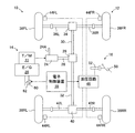
図1はトランスファを備えた四輪駆動車に適用された本発明による車両の車速制御装置の一つの実施例を示す概略構成図、図2は図1に示された電子制御装置を示すブロック図である。 FIG. 1 is a schematic configuration diagram showing one embodiment of a vehicle speed control device according to the present invention applied to a four-wheel drive vehicle equipped with a transfer, and FIG. 2 is a block diagram showing the electronic control device shown in FIG. It is.
図1に於いて、10は車両12の車速制御装置を全体的に示しており、車速制御装置10は駆動装置14と制動装置16と電子制御装置18とを有している。駆動装置14はエンジン20を含み、エンジン20の駆動力はトランスミッション22及びトランスファ24を介して出力シャフト26へ伝達され、出力シャフト26の駆動力はセンタディファレンシャル28により前輪用プロペラシャフト30及び後輪用プロペラシャフト32へ伝達される。
In FIG. 1,
トランスファ24はエンジン20の駆動トルクをセンタディファレンシャル28へ高速ギヤ比にて伝達するHレンジ(高速伝達位置)と低速ギヤ比にて伝達するLレンジ(低速伝達位置)とを有する副変速機を含んでいる。トランスファ24のシフトポジションの切り換えは運転者により操作レバー24Aが操作されることにより行われる。
The
前輪用プロペラシャフト30の駆動力はフロントディファレンシャル34により左前輪用ドライブシャフト36L及び右前輪用ドライブシャフト36Rへ伝達され、これにより左前輪38FL及び右前輪38FRが回転駆動される。同様に後輪用プロペラシャフト32の駆動力はリヤディファレンシャル40により左後輪用プロペラシャフト42L及び右後輪用プロペラシャフト42Rへ伝達され、これにより左後輪38RL及び右後輪38RRが回転駆動される。図示の実施例に於いては、センタディファレンシャル28、フロントディファレンシャル34、リヤディファレンシャル40にはロック装置は設けられていない。
The driving force of the front
左右前輪38FL、38FR及び左右後輪38RL、38RRにはそれぞれ対応する車輪の制動力を発生するためのホイールシリンダ44FL、44FR、44RL、44RRが設けられており、制動装置16は油圧回路48により対応するホイールシリンダ44FL〜44RRの制動圧を制御することによって各車輪の制動力を制御する。図1には詳細に示されていないが、油圧回路48はリザーバ、オイルポンプ、種々の弁装置等を含み、各ホイールシリンダの制動圧は通常時には運転者によるブレーキペダル50の踏み込み操作に応じて駆動されるマスタシリンダ52により制御され、また必要に応じて後に詳細に説明する如く電子制御装置18により制御される。
The left and right front wheels 38FL, 38FR and the left and right rear wheels 38RL, 38RR are provided with wheel cylinders 44FL, 44FR, 44RL, 44RR, respectively, for generating the braking force of the corresponding wheels. The braking force of each wheel is controlled by controlling the braking pressure of the wheel cylinders 44FL to 44RR. Although not shown in detail in FIG. 1, the
尚周知の如く、エンジン20の出力はスロットルバルブアクチュエータ60によってスロットルバルブ62の開度が変化されることにより制御され、スロットルバルブ62の開度は図1には示されていないアクセルペダルに対する運転者の踏み込み操作量に応じて制御される。
As is well known, the output of the
尚図1及び図2には詳細に示されていないが、電子制御装置18は車速制御用のマイクロコンピュータと、エンジン20を制御するマイクロコンピュータと、トランスミッション22を制御するマイクロコンピュータと、制動装置16を制御するマイクロコンピュータとを含み、各マイクロコンピュータはそれぞれ双方向性のコモンバスにより互いに接続されたCPUとROMとRAMと入出力ポート装置とを有していてよい。
Although not shown in detail in FIGS. 1 and 2, the
電子制御装置18にはエンジン20及びトランスミッション22を制御するために必要な情報に加えて、車速センサ70より車速Vを示す信号、圧力センサ72よりマスタシリンダ圧力Pmを示す信号、アクセル開度センサ74よりアクセル開度φを示す信号、前後加速度センサ76より車両の前後加速度Gxを示す信号、運転者により操作される車速制限スイッチ78がオン状態にあるか否かを示す信号が入力されるようになっている。車速制限スイッチ78は通常時はオフ状態にあり、トランスファ24のシフトポジションがLレンジであるときにのみ運転者の操作によりオン状態に切り替えることが可能である。
In addition to information necessary for controlling the
電子制御装置18は、車速制限スイッチ78がオフ状態にあるときには、当技術分野に於いて公知の要領にてエンジン20、トランスミッション22、制動装置16を制御する。これに対し電子制御装置18は、車速制限スイッチ78がオン状態にあるときには、車速センサ70により検出される車速Vが上限車速Vulimを越えないよう、エンジン20及びトランスミッション22の制御によって車両の駆動力を制御すると共に、制動装置16の制御によって車両の制動力を制御し、これにより車速を制限する。特に図示の実施例に於ける車速制限制御は降坂走行時の車速Vを上限車速Vulim以下に制限する制御であるが、この車速制限制御自体は本発明の要旨をなすものではないので、当技術分野に於いて公知の任意の要領にて実行されてよい。
When the vehicle
また電子制御装置18は、車速制限制御を行っている状況に於いて、運転者により車速制限スイッチ78がオフ状態に切り替えられたとき、又は異常診断により車速制御装置10が正常に作動しないと判定されたときには、車速制限制御の終了条件が成立したと判定し、車速制限制御を終了させる。
Further, the
そして電子制御装置18は、車速制限制御を終了すると、車速Vに基づいて車両の目標加速度Gxatを演算し、車両の前後加速度Gxに基づいて走行路の傾斜勾配Gslopeを推定し、走行路の傾斜勾配Gslopeに基づいて補正係数Kgを演算する。また電子制御装置18は、車速V、車両の目標加速度Gxat、補正係数Kgに基づいて車両の増速の目標車速Vatを演算し、車速Vが目標車速Vatになるよう制動装置16による制動力を低減することによって増速制御する。
When the vehicle speed limit control is finished, the
更に電子制御装置18は、増速制御中に増速制御の終了条件が成立したか否かを判定し、増速制御の終了条件が成立したと判定したときには、増速制御を終了する。この場合全ての車輪の制動力が0になったとき又は運転者により加減速操作が行われたときに増速制御の終了条件が成立したと判定されてよい。
Further, the
次に図3に示されたフローチャートを参照して実施例に於ける増速制御ルーチンについて説明する。尚図3に示されたフローチャートによる制御は速度制限制御の開始により開始され、所定の時間毎に繰返し実行される。 Next, the speed increasing control routine in the embodiment will be described with reference to the flowchart shown in FIG. Note that the control according to the flowchart shown in FIG. 3 is started at the start of the speed limit control and is repeatedly executed at predetermined time intervals.
まずステップ310に於いては、車速センサ70により検出された車速Vを示す信号等の読み込みが行われ、ステップ320に於いては、下記の条件A1及びA2の何れかが成立しているか否かの判別により、速度制限制御の終了条件が成立しているか否かの判別が行われ、否定判別が行われたときにはステップ310へ戻り、肯定判別が行われたときにはステップ330へ進む。
A1:運転者により車速制限スイッチ78がオフ状態に切り替えられた
A2:異常診断により車速制御装置10が正常に作動しないと判定された
First, in
A1: The vehicle
ステップ330に於いては、例えば車両の前後加速度Gxがロータパスフィルタ処理されることにより前後加速度Gxの定常成分が抽出され、前後加速度Gxの定常成分に基づいて走行路の傾斜勾配Gslopeが推定される。かくしてこの実施例に於いては、前後加速度センサ76は走行路の勾配を取得する手段の一部として機能する。
In
ステップ340に於いては、走行路の傾斜勾配Gslopeに基づいて図4に示されたグラフに対応するマップより補正係数Kg(正の値)が演算される。この場合図4に示されている如く、走行路が降坂である場合には傾斜勾配Gslopeの大きさが大きいほど補正係数Kgは1以下の範囲にて小さくなり、逆に走行路が登坂である場合には傾斜勾配Gslopeの大きさが大きいほど補正係数Kgは1以上の範囲にて大きくなる。
In
ステップ350に於いては、車速Vに基づいて図5に示されたグラフに対応するマップより車両の目標加速度Gxat(正の値)が演算される。この場合図5に示されている如く、目標加速度Gxatは車速Vが高いほど大きい値になるよう演算される。
In
ステップ360に於いては、前サイクルの車両の目標車速VatをVat(n-1)とし、図3に示されたフローチャートによる制御のサイクルタイムをTcとして、下記の式1に従って車両の目標車速Vatが演算される。尚ステップ320に於いて肯定判別が行われた直後に目標車速Vatが演算される際には、Vat(n-1)は前サイクルに於いて車速センサ70により検出された車速Vに設定される。
Vat=Vat(n-1)+KgGxatTc ……(1)
In
Vat = Vat (n-1) + KgGxatTc (1)
ステップ370に於いては、現在の車速Vと目標車速Vatとの偏差ΔVの大きさが0になるよう、偏差ΔVに基づき各車輪の目標制駆動力が演算されると共に、各車輪の制駆動力がそれぞれ対応する目標制駆動力になるよう制御されることにより、車速Vが目標車速Vatになるよう制御される。
In
ステップ380に於いては、下記の条件B1及びB2の何れかが成立しているか否かの判別により、増速制御の終了条件が成立しているか否かの判別が行われ、否定判別が行われたときにはステップ330へ戻り、肯定判別が行われたときには図3に示されたフローチャートによる制御が終了される。
B1:全ての車輪の制動力が0になった
B2:運転者により加減速操作が行われた
In
B1: Braking force of all wheels became 0 B2: Acceleration / deceleration operation was performed by the driver
かくして図示の実施例によれば、速度制限制御の終了条件が成立すると、ステップ320に於いて肯定判別が行われ、ステップ330に於いて前後加速度Gxの定常成分に基づいて走行路の傾斜勾配Gslopeが推定され、ステップ340に於いて走行路の傾斜勾配Gslopeに基づいて補正係数Kgが演算される。またステップ350に於いて車速Vに基づいて車両の目標加速度Gxatが演算され、ステップ360に於いて補正係数Kgと目標加速度Gxatと図3に示されたフローチャートによる制御のサイクルタイムTcとの積と、前サイクルの車両の目標車速Vat(n-1)との和として目標車速Vatが演算される。そしてステップ370に於いて車速Vが目標車速Vatになるよう各車輪の制駆動力が制御される。
Thus, according to the illustrated embodiment, when the speed limit control termination condition is satisfied, an affirmative determination is made in
従って図示の実施例によれば、車速制限制御終了後の車両の増速勾配を車速Vに応じて可変制御することができ、これにより車速に拘らず増速勾配が一定である場合に比して、車速制限制御終了後の車両の増速時に車両の乗員が覚える違和感を確実に低減することができる。 Therefore, according to the illustrated embodiment, it is possible to variably control the acceleration gradient of the vehicle after completion of the vehicle speed limiting control in accordance with the vehicle speed V, thereby comparing with the case where the acceleration gradient is constant regardless of the vehicle speed. Thus, it is possible to reliably reduce the uncomfortable feeling that is felt by the vehicle occupant when the vehicle speed increases after the vehicle speed limit control is completed.
例えば図6は車速Vに拘らず車速制限制御終了後の車両の増速勾配が一定である従来の車速制御装置に於ける車速制限制御及び増速制御を高車速の場合(A)及び低車速の場合(B)について示すグラフである。図6に示されている如く、車速Vに拘らず車速制限制御終了後(時点t1以降)の車両の増速勾配が一定である場合には、増速勾配が高い値に設定されると、車両の乗員は低車速の場合に車速制限制御終了後の車両の増速勾配が高すぎることに起因して違和感を覚え、増速勾配が低い値に設定されると、車両の乗員は高車速の場合に車速制限制御終了後の車両の増速勾配が低すぎることに起因して違和感を覚えることが避けられない。 For example, FIG. 6 shows a case in which the vehicle speed limiting control and the speed increasing control in the conventional vehicle speed control device in which the speed increasing gradient of the vehicle after the vehicle speed limiting control ends is constant regardless of the vehicle speed V when the vehicle speed is high (A) and the low vehicle speed. It is a graph shown about (B) in the case of. As shown in FIG. 6, when the acceleration gradient of the vehicle after the end of the vehicle speed limit control (after time t1) is constant regardless of the vehicle speed V, if the acceleration gradient is set to a high value, The vehicle occupant feels uncomfortable due to the vehicle's acceleration gradient being too high after the vehicle speed limit control at low vehicle speed, and if the vehicle acceleration gradient is set to a low value, the vehicle occupant In this case, it is inevitable that the vehicle will feel uncomfortable due to the vehicle speed increasing gradient being too low after the vehicle speed limiting control is completed.
これに対し図示の実施例によれば、図7に示されている如く、車速制限制御が終了する時刻t1の時点での車速が高車速の場合(A)には時点t1での車速が低車速の場合(B)に比して車速制限制御終了後の車両の増速勾配を大きくし、逆に低車速の場合(B)には高車速の場合(A)に比して車速制限制御終了後の車両の増速勾配を小さくすることができ、従って車速に応じて車両の増速勾配を最適に可変設定し、車両の乗員が違和感を覚えることを確実に防止することができる。 On the other hand, according to the illustrated embodiment, as shown in FIG. 7, when the vehicle speed at the time t1 when the vehicle speed restriction control ends is high (A), the vehicle speed at the time t1 is low. The vehicle speed-increasing gradient after the vehicle speed limit control is finished is larger than that in the case of vehicle speed (B). Conversely, in the case of low vehicle speed (B), the vehicle speed limit control is higher than in the case of high vehicle speed (A). The acceleration gradient of the vehicle after the completion can be reduced, and accordingly, the acceleration gradient of the vehicle can be optimally variably set according to the vehicle speed, and the vehicle occupant can be reliably prevented from feeling uncomfortable.
特に図示の実施例によれば、車両の目標加速度Gxatは車速Vが高いほど大きくなるよう演算されるので、車両の乗員が低車速域に於いて増速勾配が大き過ぎると感じることを防止することができると共に、高車速域に於いて増速勾配が小さ過ぎると感じることを防止することができる。 In particular, according to the illustrated embodiment, the target acceleration Gxat of the vehicle is calculated so as to increase as the vehicle speed V increases, thereby preventing the vehicle occupant from feeling that the acceleration gradient is too large in the low vehicle speed range. It is possible to prevent the acceleration gradient from being felt too small in the high vehicle speed range.
また図示の実施例によれば、補正係数Kgは降坂時には走行路の傾斜勾配Gslopeが大きいほど小さくなるよう演算されるので、走行路の降坂勾配が小さいときに車両の乗員が増速勾配が小さ過ぎると感じることを防止することができると共に、走行路の降坂勾配が大きいときに車両の乗員が増速勾配が大き過ぎると感じることを防止することができる。 Further, according to the illustrated embodiment, the correction coefficient Kg is calculated so as to decrease as the slope gradient Gslope of the traveling road increases when descending, so that the vehicle occupant can increase the acceleration gradient when the downhill slope of the traveling road is small. It is possible to prevent the vehicle occupant from feeling that the acceleration gradient is too large when the downhill gradient of the traveling road is large.
例えば図8に示されている如く、車速制限制御が終了する時刻t2の時点で推定された走行路の降坂の傾斜勾配Gslopeが大きい場合(C)には降坂の傾斜勾配Gslopeが小さい場合(D)に比して車速制限制御終了後の車両の増速勾配を小さくすることができ、これにより走行路の降坂勾配が小さいときに於ける増速勾配が小さくなり過ぎることを防止しつつ、走行路の降坂勾配が大きいときに増速勾配が大きくなり過ぎることを防止し、車両の乗員が違和感を覚えることを確実に防止することができる。 For example, as shown in FIG. 8, when the slope Gslope of the downhill of the travel path estimated at the time t2 when the vehicle speed limiting control ends is large (C), the slope Gslope of the downhill is small. Compared to (D), the vehicle acceleration gradient after the vehicle speed limit control is completed can be reduced, thereby preventing the acceleration gradient from becoming too small when the downhill gradient of the travel path is small. On the other hand, it is possible to prevent the acceleration gradient from becoming too large when the downhill gradient of the travel path is large, and to reliably prevent the vehicle occupant from feeling uncomfortable.
また図示の実施例によれば、登坂時には走行路の傾斜勾配Gslopeが大きいほど大きくなるよう演算されるので、走行路の登坂勾配が大きいときに車両の乗員が増速勾配が小さ過ぎると感じることを防止することができると共に、走行路の登坂勾配が小さいときに車両の乗員が増速勾配が大き過ぎると感じることを防止することができる。 Also, according to the illustrated embodiment, when the hill is climbed, the larger the slope gradient Gslope of the traveling road, the larger the slope is calculated, so that the occupant of the vehicle feels that the acceleration slope is too small when the slope of the traveling road is large. In addition, it is possible to prevent the occupant of the vehicle from feeling that the acceleration gradient is too large when the climbing gradient of the travel path is small.
以上に於いては本発明を特定の実施例について詳細に説明したが、本発明は上述の実施例に限定されるものではなく、本発明の範囲内にて他の種々の実施例が可能であることは当業者にとって明らかであろう。 Although the present invention has been described in detail with reference to specific embodiments, the present invention is not limited to the above-described embodiments, and various other embodiments are possible within the scope of the present invention. It will be apparent to those skilled in the art.
例えば上述の実施例に於いては、車両の前後加速度Gxがロータパスフィルタ処理されることにより前後加速度Gxの定常成分が抽出され、前後加速度Gxの定常成分に基づいて走行路の傾斜勾配Gslopeが推定されるようになっているが、走行路の傾斜勾配Gslopeは当技術分野に於いて公知の任意の要領にて推定されてよく、例えば車高に基づいて推定されてもよい。 For example, in the above-described embodiment, the steady-state component of the longitudinal acceleration Gx is extracted by subjecting the longitudinal acceleration Gx of the vehicle to the rotor-pass filter processing, and the slope Gslope of the traveling road is calculated based on the steady-state component of the longitudinal acceleration Gx. Although it is estimated, the slope Gslope of the traveling road may be estimated in any manner known in the art, and may be estimated based on the vehicle height, for example.
また上述の実施例に於いては、補正係数Kgは走行路が登坂である場合についても傾斜勾配Gslopeの大きさが大きいほど1以上の範囲にて大きくなるよう演算されるようになっているが、登坂である場合について補正係数Kgの演算は省略され、その場合の係数は1に設定されてもよい。 In the above-described embodiment, the correction coefficient Kg is calculated so as to increase in a range of 1 or more as the inclination gradient Gslope increases, even when the traveling road is uphill. The calculation of the correction coefficient Kg may be omitted for the case of climbing, and the coefficient in that case may be set to 1.
更に上述の実施例に於いては、車両はトランスファを備えた四輪駆動車であるが、本発明による車速制御装置は車速を上限車速以下に制限する車速制限制御を行うと共に、車速制限制御が終了すると車両の増速勾配が目標増速勾配になるよう増速制御を行う限り、任意の車両に適用されてよい。 Further, in the above-described embodiment, the vehicle is a four-wheel drive vehicle equipped with a transfer. However, the vehicle speed control device according to the present invention performs vehicle speed limit control for limiting the vehicle speed to the upper limit vehicle speed or less, and vehicle speed limit control is performed. As long as the speed increase control is performed so that the vehicle speed increase gradient becomes the target speed increase gradient after completion, the present invention may be applied to any vehicle.
10…車速制御装置、14…駆動装置、16…制動装置、18…電子制御装置、20…エンジン、22…トランスミッション、24…トランスファ、28…センタディファレンシャル、34…フロントディファレンシャル、40…リヤディファレンシャル、44FL、44FR、44RL、44RR…ホイールシリンダ
DESCRIPTION OF
Claims (8)
Priority Applications (5)
| Application Number | Priority Date | Filing Date | Title |
|---|---|---|---|
| JP2007119576A JP4938542B2 (en) | 2007-04-27 | 2007-04-27 | Vehicle speed control device for vehicle |
| US12/450,580 US8818677B2 (en) | 2007-04-27 | 2008-04-23 | System and method of vehicle speed control having vehicle speed limit control and speed increase rate control |
| PCT/IB2008/000998 WO2008132577A1 (en) | 2007-04-27 | 2008-04-23 | Vehicle speed control system and vehicle speed control method of vehicle |
| DE112008000789.6T DE112008000789B4 (en) | 2007-04-27 | 2008-04-23 | Vehicle speed control system and vehicle speed control method of a vehicle |
| CN2008800138141A CN101678768B (en) | 2007-04-27 | 2008-04-23 | Vehicle speed control system and vehicle speed control method of vehicle |
Applications Claiming Priority (1)
| Application Number | Priority Date | Filing Date | Title |
|---|---|---|---|
| JP2007119576A JP4938542B2 (en) | 2007-04-27 | 2007-04-27 | Vehicle speed control device for vehicle |
Publications (2)
| Publication Number | Publication Date |
|---|---|
| JP2008273387A JP2008273387A (en) | 2008-11-13 |
| JP4938542B2 true JP4938542B2 (en) | 2012-05-23 |
Family
ID=39688834
Family Applications (1)
| Application Number | Title | Priority Date | Filing Date |
|---|---|---|---|
| JP2007119576A Active JP4938542B2 (en) | 2007-04-27 | 2007-04-27 | Vehicle speed control device for vehicle |
Country Status (5)
| Country | Link |
|---|---|
| US (1) | US8818677B2 (en) |
| JP (1) | JP4938542B2 (en) |
| CN (1) | CN101678768B (en) |
| DE (1) | DE112008000789B4 (en) |
| WO (1) | WO2008132577A1 (en) |
Families Citing this family (27)
| Publication number | Priority date | Publication date | Assignee | Title |
|---|---|---|---|---|
| US9255529B2 (en) * | 2010-02-23 | 2016-02-09 | Honda Motor Co., Ltd. | Longitudinal G adjusted throttle response |
| DE102010003428A1 (en) * | 2010-03-30 | 2011-10-06 | Robert Bosch Gmbh | Traveling speed controller for use in control system for hybrid drive system of motor car, has control device making deviation of velocity based on actual value of condition parameter affecting power consumption of drive system of motor car |
| US8818597B2 (en) * | 2010-05-13 | 2014-08-26 | Honda Motor Co., Ltd. | Vehicle control device |
| JP5990947B2 (en) * | 2012-03-13 | 2016-09-14 | 日産自動車株式会社 | Vehicle control device |
| JP5569550B2 (en) * | 2012-03-30 | 2014-08-13 | 株式会社アドヴィックス | Vehicle braking control device and vehicle braking control method |
| US9139222B2 (en) * | 2012-03-30 | 2015-09-22 | Deere & Company | Self tuning universal steering control system, method, and apparatus for off-road vehicles |
| EP2885174B1 (en) * | 2012-08-16 | 2019-05-01 | Jaguar Land Rover Limited | Vehicle speed control system and method with external force compensation |
| GB2508459B (en) * | 2012-08-16 | 2015-01-21 | Jaguar Land Rover Ltd | System and method for controlling vehicle speed to enhance occupant comfort |
| DE112013005524T5 (en) * | 2012-12-07 | 2015-07-30 | Kelsey-Hayes Company | Vehicle speed control system |
| US8843288B1 (en) | 2013-03-14 | 2014-09-23 | Chrysler Group Llc | Vehicle speed control system and method |
| GB2511841B (en) * | 2013-03-15 | 2015-02-25 | Jaguar Land Rover Ltd | Vehicle speed control system and method |
| JP5892108B2 (en) * | 2013-05-13 | 2016-03-23 | トヨタ自動車株式会社 | Vehicle speed control device |
| GB2519533B (en) | 2013-10-23 | 2018-04-04 | Jaguar Land Rover Ltd | Vehicle speed control system |
| JP6439348B2 (en) * | 2014-09-25 | 2018-12-19 | いすゞ自動車株式会社 | Vehicle control device |
| KR101601553B1 (en) * | 2014-12-03 | 2016-03-21 | 현대자동차주식회사 | Driving control system of vehicle and method for changing speed setting mode using thereof |
| SE539688C2 (en) | 2014-12-05 | 2017-10-31 | Scania Cv Ab | Apparatus and method for controlling a velocity of a bus |
| KR101655594B1 (en) | 2014-12-08 | 2016-09-22 | 현대자동차주식회사 | Device and method for controlling auto cruise of vehicle |
| JP6191644B2 (en) * | 2015-03-26 | 2017-09-06 | トヨタ自動車株式会社 | Vehicle speed limiter |
| US9865413B2 (en) * | 2015-04-10 | 2018-01-09 | Honda Motor Co., Ltd. | Vehicle control device |
| CN106042928A (en) * | 2016-06-24 | 2016-10-26 | 桂林金铱星科技发展有限公司 | Speed limiting prompt device for automobile |
| CN109572448A (en) * | 2018-12-29 | 2019-04-05 | 中国重汽集团济南动力有限公司 | A kind of pure electric automobile auxiliary control method and its control system based on ramp sensor |
| CN110371128B (en) * | 2019-06-26 | 2021-10-08 | 江铃汽车股份有限公司 | Steep descent control method and device and readable storage medium |
| CN110733491A (en) * | 2019-10-30 | 2020-01-31 | 东软睿驰汽车技术(沈阳)有限公司 | vehicle speed control method and device and vehicle |
| JP7327105B2 (en) | 2019-11-20 | 2023-08-16 | 株式会社アドヴィックス | Braking control device |
| CN111731298B (en) * | 2020-06-30 | 2022-06-03 | 重庆长安汽车股份有限公司 | Speed limit control method and device for new energy automobile and new energy automobile |
| JP7402847B2 (en) * | 2021-09-17 | 2023-12-21 | 株式会社アドヴィックス | Vehicle control device |
| JP7582143B2 (en) * | 2021-09-24 | 2024-11-13 | トヨタ自動車株式会社 | Vehicle driving assistance device, vehicle driving assistance method, and vehicle driving assistance program |
Family Cites Families (71)
| Publication number | Priority date | Publication date | Assignee | Title |
|---|---|---|---|---|
| JPS5231414A (en) * | 1975-09-03 | 1977-03-09 | Hitachi Ltd | Safety device for electromobile |
| JPS6050034A (en) | 1983-08-30 | 1985-03-19 | Nippon Denso Co Ltd | Controlling device for speed of vehicle |
| JPS611549A (en) * | 1984-06-13 | 1986-01-07 | Nippon Denso Co Ltd | Car-speed controller for automobile |
| DE3644138C1 (en) * | 1986-12-23 | 1988-07-07 | Daimler Benz Ag | Device for regulating the propulsion of motor vehicles |
| SE460781B (en) * | 1988-03-31 | 1989-11-20 | Saab Scania Ab | PROCEDURES AND ARRANGEMENTS FOR CONSTANT MAINTENANCE OF MOTOR VEHICLES DURING DOWN THE DOWN BACK |
| US5019986A (en) * | 1990-04-27 | 1991-05-28 | Caterpillar Inc. | Method of operating a vehicle engine |
| US5646850A (en) * | 1990-06-13 | 1997-07-08 | Matsushita Electric Industrial Co., Ltd. | Auto-drive control apparatus for use in vehicle apparatus |
| US5177682A (en) * | 1991-08-09 | 1993-01-05 | Ford Motor Company | Speed control system with resume mode override |
| JP2946881B2 (en) * | 1991-11-11 | 1999-09-06 | トヨタ自動車株式会社 | Throttle valve control device for internal combustion engine |
| US5287773A (en) * | 1992-01-31 | 1994-02-22 | Toyota Jidosha Kabushiki Kaisha | Apparatus for controlling engine brake force during vehicle running on downhill with released accelerator |
| JPH06144080A (en) * | 1992-11-12 | 1994-05-24 | Jidosha Denki Kogyo Co Ltd | Control method of automatic constant speed traveling device |
| JPH06229279A (en) * | 1993-02-04 | 1994-08-16 | Fuji Heavy Ind Ltd | Throttle device for self-traveling |
| GB9303434D0 (en) * | 1993-02-20 | 1993-04-07 | Lucas Ind Plc | Method of and apparatus for cruise control |
| JPH08318765A (en) * | 1995-05-25 | 1996-12-03 | Hitachi Ltd | Information vehicle control apparatus and method |
| JP3588868B2 (en) * | 1995-08-04 | 2004-11-17 | 日産自動車株式会社 | Driving force control device for vehicles |
| DE19641059B4 (en) * | 1995-10-05 | 2007-08-16 | Nissan Motor Co., Ltd., Yokohama | Control device and control method for controlling a continuously variable transmission |
| US5722500A (en) * | 1995-10-12 | 1998-03-03 | Nissan Motor Co., Ltd. | Continuously variable transmission control apparatus |
| JPH09207612A (en) * | 1996-02-09 | 1997-08-12 | Jidosha Denki Kogyo Co Ltd | Automatic constant speed travel gear |
| DE19702312C2 (en) * | 1997-01-23 | 2000-06-21 | Daimler Chrysler Ag | Device for controlling and / or regulating the longitudinal speed of a motor vehicle |
| JPH1120498A (en) * | 1997-06-27 | 1999-01-26 | Denso Corp | Automatic cruise controller |
| JP3930110B2 (en) * | 1997-08-11 | 2007-06-13 | 富士重工業株式会社 | Vehicle cruise control device |
| JP4037506B2 (en) * | 1998-03-12 | 2008-01-23 | 富士重工業株式会社 | Vehicle motion control device |
| DE19933389A1 (en) * | 1998-07-29 | 2000-02-03 | Continental Teves Ag & Co Ohg | Method to identify bad stretch of road being driven on by vehicle and to control vehicle speed accordingly |
| GB9816521D0 (en) * | 1998-07-29 | 1998-09-30 | Lucas Ind Plc | Vehicle cruise control with automatic set speed reduction |
| GB9818960D0 (en) * | 1998-09-02 | 1998-10-21 | Rover Group | A vehicle |
| GB9819519D0 (en) * | 1998-09-09 | 1998-10-28 | Rover Group | Vehicle brake control |
| US6441431B1 (en) * | 1998-12-04 | 2002-08-27 | Texas Instruments Incorporated | Lateral double diffused metal oxide semiconductor device |
| DE19858294C2 (en) * | 1998-12-17 | 2000-11-02 | Daimler Chrysler Ag | Method for controlling the speed of a motor vehicle |
| DE19901527C1 (en) * | 1999-01-16 | 2000-07-06 | Porsche Ag | Method for regulating the driving speed of a motor vehicle |
| JP3656464B2 (en) * | 1999-06-15 | 2005-06-08 | 日産自動車株式会社 | Leading vehicle tracking control device |
| JP3627582B2 (en) * | 1999-07-30 | 2005-03-09 | 日産自動車株式会社 | Vehicle tracking control device |
| US6493618B2 (en) * | 2000-03-15 | 2002-12-10 | Toyota Jidosha Kabushiki Kaisha | Vehicle control using multiple sensors |
| JP3607981B2 (en) * | 2000-04-19 | 2005-01-05 | トヨタ自動車株式会社 | Vehicle deceleration control device |
| EP1155900B8 (en) * | 2000-05-16 | 2007-09-19 | Nissan Motor Company, Limited | Vehicle speed control system |
| US6253141B1 (en) * | 2000-05-23 | 2001-06-26 | Valeo Electrical Systems, Inc. | Braking control system for vehicle |
| US6470256B1 (en) * | 2000-08-25 | 2002-10-22 | Visteon Global Technologies, Inc. | Fuel economizing cruise control |
| US6945346B2 (en) * | 2000-09-28 | 2005-09-20 | Automotive Distance Control Systems Gmbh | Method for operating a driver support system for motor vehicles |
| JP3788240B2 (en) * | 2001-01-18 | 2006-06-21 | 日産自動車株式会社 | Vehicle tracking control device |
| JP3812391B2 (en) * | 2001-09-26 | 2006-08-23 | 日産自動車株式会社 | Vehicle driving force control device |
| DE10153527A1 (en) * | 2001-10-30 | 2003-05-15 | Bosch Gmbh Robert | Device for the longitudinal guidance of a motor vehicle |
| JP2003205762A (en) * | 2002-01-11 | 2003-07-22 | Toyota Motor Corp | Travel control device |
| JP2004123081A (en) * | 2002-08-06 | 2004-04-22 | Honda Motor Co Ltd | Vehicle follower |
| US6580996B1 (en) * | 2002-08-07 | 2003-06-17 | Visteon Global Technologies, Inc. | Vehicle adaptive cruise control system and method |
| JP4039184B2 (en) * | 2002-08-29 | 2008-01-30 | 株式会社アドヴィックス | Creep travel control device |
| JP3918686B2 (en) * | 2002-08-30 | 2007-05-23 | 株式会社日立製作所 | Driving control apparatus and control method for automobile |
| DE10241059A1 (en) * | 2002-09-05 | 2004-03-18 | Robert Bosch Gmbh | Method and device for limiting the speed of a vehicle |
| WO2004037623A1 (en) * | 2002-10-28 | 2004-05-06 | Hitachi Construction Machinery Co., Ltd. | Downhill speed controller |
| JP2005001632A (en) * | 2003-06-16 | 2005-01-06 | Nissan Motor Co Ltd | Automotive constant speed travel control device |
| JP4541785B2 (en) * | 2003-09-01 | 2010-09-08 | キヤノン株式会社 | Vibration type actuator drive control device and vibration type actuator drive control method |
| JP2005113734A (en) * | 2003-10-06 | 2005-04-28 | Hino Motors Ltd | Accelerator control device |
| JP2005127424A (en) * | 2003-10-24 | 2005-05-19 | Nissan Motor Co Ltd | Vehicle driving force control device |
| JP2005186813A (en) * | 2003-12-25 | 2005-07-14 | Fuji Heavy Ind Ltd | Vehicle driving support device |
| JP4176690B2 (en) * | 2004-09-03 | 2008-11-05 | 本田技研工業株式会社 | Vehicle travel control device |
| US7107138B2 (en) * | 2004-11-02 | 2006-09-12 | Joseph Edward Currie | Automotive speed control disable switch |
| US20060212205A1 (en) * | 2005-03-15 | 2006-09-21 | Continental Teves, Inc. | Method for detecting when a vehicle is in a downhill situation |
| JP4943661B2 (en) * | 2005-03-31 | 2012-05-30 | 日立オートモティブシステムズ株式会社 | Pedal device and automobile equipped with the same |
| JP4792801B2 (en) * | 2005-04-21 | 2011-10-12 | 株式会社アドヴィックス | Vehicle speed control device |
| JP2006307798A (en) * | 2005-05-02 | 2006-11-09 | Toyota Motor Corp | Travel control device |
| US7319927B1 (en) * | 2005-05-12 | 2008-01-15 | Kelsey-Hayes Company | Constant speed control system |
| JP4557817B2 (en) * | 2005-06-17 | 2010-10-06 | アイシン精機株式会社 | Driving support device |
| JP4462148B2 (en) * | 2005-09-01 | 2010-05-12 | 株式会社デンソー | Cruise control equipment |
| DE102005060820B4 (en) * | 2005-12-20 | 2022-05-19 | Zf Cv Systems Hannover Gmbh | Method for assisting in driving a vehicle |
| JP4867561B2 (en) * | 2005-12-22 | 2012-02-01 | 日産自動車株式会社 | VEHICLE DRIVE OPERATION ASSISTANCE DEVICE AND VEHICLE WITH VEHICLE DRIVE OPERATION ASSISTANCE DEVICE |
| JP4796400B2 (en) * | 2006-02-01 | 2011-10-19 | クラリオン株式会社 | Vehicle speed control device, target speed setting method and program in the same |
| JP4169065B2 (en) * | 2006-02-13 | 2008-10-22 | 株式会社デンソー | Vehicle control device |
| US7184873B1 (en) * | 2006-05-05 | 2007-02-27 | Stanox Technologies Inc. | Vehicle speed limiting device |
| DE102007040539B4 (en) * | 2006-09-04 | 2014-03-27 | Denso Corporation | Vehicle control system |
| WO2008066170A1 (en) * | 2006-11-30 | 2008-06-05 | Tcm Corporation | Speed change control system for industrial vehicle |
| JP4197037B2 (en) * | 2007-03-14 | 2008-12-17 | トヨタ自動車株式会社 | Hybrid vehicle and control method thereof |
| JP4931714B2 (en) * | 2007-07-11 | 2012-05-16 | 株式会社デンソー | Vehicle speed control device and vehicle speed control program |
| US8380419B2 (en) * | 2009-03-27 | 2013-02-19 | Zf Friedrichshafen Ag | Resume speed adaptation for automatic vehicle acceleration at a rate derived from a measured acceleration rate |
-
2007
- 2007-04-27 JP JP2007119576A patent/JP4938542B2/en active Active
-
2008
- 2008-04-23 US US12/450,580 patent/US8818677B2/en active Active
- 2008-04-23 CN CN2008800138141A patent/CN101678768B/en active Active
- 2008-04-23 WO PCT/IB2008/000998 patent/WO2008132577A1/en not_active Ceased
- 2008-04-23 DE DE112008000789.6T patent/DE112008000789B4/en active Active
Also Published As
| Publication number | Publication date |
|---|---|
| DE112008000789T5 (en) | 2010-03-25 |
| WO2008132577A8 (en) | 2009-10-22 |
| US8818677B2 (en) | 2014-08-26 |
| US20100100295A1 (en) | 2010-04-22 |
| CN101678768B (en) | 2013-01-30 |
| DE112008000789B4 (en) | 2020-03-26 |
| CN101678768A (en) | 2010-03-24 |
| WO2008132577A1 (en) | 2008-11-06 |
| JP2008273387A (en) | 2008-11-13 |
Similar Documents
| Publication | Publication Date | Title |
|---|---|---|
| JP4938542B2 (en) | Vehicle speed control device for vehicle | |
| JP4396002B2 (en) | Vehicle traction control device | |
| JP5610369B2 (en) | Vehicle shift control device | |
| US8271159B2 (en) | Method and control system for stabilizing a vehicle | |
| CN113415280B (en) | Mode switching control method, device, equipment and automobile | |
| JP5165794B2 (en) | Vehicle braking force control device | |
| CN110239520B (en) | Yaw moment control device for vehicle | |
| CN101163618A (en) | Driving force control apparatus and driving force control method | |
| CN101084143B (en) | vehicle control device | |
| JP2002054730A (en) | Automatic transmission control device | |
| US6311115B2 (en) | Method and system for controlling a drive train of a motor vehicle | |
| CN115503680B (en) | Drive control device | |
| CN113386734B (en) | Driving force control device | |
| JP2012192875A (en) | Driving support control device for vehicle | |
| JP4910361B2 (en) | Vehicle driving force control device | |
| JP3972204B2 (en) | Vehicle driving force control device | |
| JPH11278088A (en) | Vehicle torque distribution clutch control device and vehicle parking brake turn determination device | |
| JP4784741B2 (en) | Vehicle driving force control device | |
| CN100564842C (en) | Vehicle engine output control device and control method | |
| JP5912505B2 (en) | Vehicle travel support device | |
| JP4674543B2 (en) | Vehicle braking / driving force control apparatus having torque converter in drive system | |
| JP2008267587A (en) | Vehicle braking / driving force control apparatus and vehicle braking / driving force control method | |
| JP2004324627A (en) | Vehicle behavior control device | |
| JP4826252B2 (en) | Vehicle braking / driving force control apparatus having torque converter in drive system | |
| JP2863292B2 (en) | Anti-skid brake system for vehicles |
Legal Events
| Date | Code | Title | Description |
|---|---|---|---|
| A621 | Written request for application examination |
Free format text: JAPANESE INTERMEDIATE CODE: A621 Effective date: 20091204 |
|
| A131 | Notification of reasons for refusal |
Free format text: JAPANESE INTERMEDIATE CODE: A131 Effective date: 20111026 |
|
| A977 | Report on retrieval |
Free format text: JAPANESE INTERMEDIATE CODE: A971007 Effective date: 20111031 |
|
| A521 | Request for written amendment filed |
Free format text: JAPANESE INTERMEDIATE CODE: A523 Effective date: 20111226 |
|
| TRDD | Decision of grant or rejection written | ||
| A01 | Written decision to grant a patent or to grant a registration (utility model) |
Free format text: JAPANESE INTERMEDIATE CODE: A01 Effective date: 20120201 |
|
| A01 | Written decision to grant a patent or to grant a registration (utility model) |
Free format text: JAPANESE INTERMEDIATE CODE: A01 |
|
| A61 | First payment of annual fees (during grant procedure) |
Free format text: JAPANESE INTERMEDIATE CODE: A61 Effective date: 20120223 |
|
| FPAY | Renewal fee payment (event date is renewal date of database) |
Free format text: PAYMENT UNTIL: 20150302 Year of fee payment: 3 |
|
| R151 | Written notification of patent or utility model registration |
Ref document number: 4938542 Country of ref document: JP Free format text: JAPANESE INTERMEDIATE CODE: R151 |
|
| FPAY | Renewal fee payment (event date is renewal date of database) |
Free format text: PAYMENT UNTIL: 20150302 Year of fee payment: 3 |
|
| R250 | Receipt of annual fees |
Free format text: JAPANESE INTERMEDIATE CODE: R250 |
|
| R250 | Receipt of annual fees |
Free format text: JAPANESE INTERMEDIATE CODE: R250 |
|
| R250 | Receipt of annual fees |
Free format text: JAPANESE INTERMEDIATE CODE: R250 |
|
| R250 | Receipt of annual fees |
Free format text: JAPANESE INTERMEDIATE CODE: R250 |
|
| R250 | Receipt of annual fees |
Free format text: JAPANESE INTERMEDIATE CODE: R250 |
|
| R250 | Receipt of annual fees |
Free format text: JAPANESE INTERMEDIATE CODE: R250 |
|
| R250 | Receipt of annual fees |
Free format text: JAPANESE INTERMEDIATE CODE: R250 |
|
| R250 | Receipt of annual fees |
Free format text: JAPANESE INTERMEDIATE CODE: R250 |
|
| R250 | Receipt of annual fees |
Free format text: JAPANESE INTERMEDIATE CODE: R250 |
|
| R250 | Receipt of annual fees |
Free format text: JAPANESE INTERMEDIATE CODE: R250 |
|
| R250 | Receipt of annual fees |
Free format text: JAPANESE INTERMEDIATE CODE: R250 |
|
| R250 | Receipt of annual fees |
Free format text: JAPANESE INTERMEDIATE CODE: R250 |