US9139222B2 - Self tuning universal steering control system, method, and apparatus for off-road vehicles - Google Patents
Self tuning universal steering control system, method, and apparatus for off-road vehicles Download PDFInfo
- Publication number
- US9139222B2 US9139222B2 US13/601,691 US201213601691A US9139222B2 US 9139222 B2 US9139222 B2 US 9139222B2 US 201213601691 A US201213601691 A US 201213601691A US 9139222 B2 US9139222 B2 US 9139222B2
- Authority
- US
- United States
- Prior art keywords
- steering
- vehicle
- reduced
- target
- vehicle model
- Prior art date
- Legal status (The legal status is an assumption and is not a legal conclusion. Google has not performed a legal analysis and makes no representation as to the accuracy of the status listed.)
- Active, expires
Links
- 238000000034 method Methods 0.000 title claims abstract description 62
- 238000012546 transfer Methods 0.000 claims abstract description 32
- 239000002131 composite material Substances 0.000 claims abstract description 22
- 230000006870 function Effects 0.000 claims description 36
- 230000015654 memory Effects 0.000 claims description 16
- 238000009434 installation Methods 0.000 claims description 4
- 238000012360 testing method Methods 0.000 description 19
- 238000004422 calculation algorithm Methods 0.000 description 17
- 238000005259 measurement Methods 0.000 description 10
- 230000008569 process Effects 0.000 description 9
- 230000004044 response Effects 0.000 description 9
- 239000002689 soil Substances 0.000 description 6
- 230000005540 biological transmission Effects 0.000 description 5
- 238000013178 mathematical model Methods 0.000 description 5
- 238000004364 calculation method Methods 0.000 description 3
- 238000012937 correction Methods 0.000 description 3
- 238000010586 diagram Methods 0.000 description 3
- 230000033001 locomotion Effects 0.000 description 3
- 239000011159 matrix material Substances 0.000 description 3
- 238000012986 modification Methods 0.000 description 3
- 230000004048 modification Effects 0.000 description 3
- 230000008859 change Effects 0.000 description 2
- 238000013461 design Methods 0.000 description 2
- 238000012854 evaluation process Methods 0.000 description 2
- 230000003287 optical effect Effects 0.000 description 2
- 238000012545 processing Methods 0.000 description 2
- 238000005070 sampling Methods 0.000 description 2
- 230000001052 transient effect Effects 0.000 description 2
- 230000001133 acceleration Effects 0.000 description 1
- 230000009471 action Effects 0.000 description 1
- 238000013459 approach Methods 0.000 description 1
- 238000003491 array Methods 0.000 description 1
- 230000015556 catabolic process Effects 0.000 description 1
- 238000013016 damping Methods 0.000 description 1
- 238000006731 degradation reaction Methods 0.000 description 1
- 230000001934 delay Effects 0.000 description 1
- 238000009472 formulation Methods 0.000 description 1
- 230000005484 gravity Effects 0.000 description 1
- 238000007620 mathematical function Methods 0.000 description 1
- 230000007246 mechanism Effects 0.000 description 1
- 239000000203 mixture Substances 0.000 description 1
- 230000009467 reduction Effects 0.000 description 1
- 230000035945 sensitivity Effects 0.000 description 1
- 239000000126 substance Substances 0.000 description 1
- 230000009466 transformation Effects 0.000 description 1
- 230000001960 triggered effect Effects 0.000 description 1
Images


Classifications
-
- B—PERFORMING OPERATIONS; TRANSPORTING
- B62—LAND VEHICLES FOR TRAVELLING OTHERWISE THAN ON RAILS
- B62D—MOTOR VEHICLES; TRAILERS
- B62D6/00—Arrangements for automatically controlling steering depending on driving conditions sensed and responded to, e.g. control circuits
-
- B—PERFORMING OPERATIONS; TRANSPORTING
- B62—LAND VEHICLES FOR TRAVELLING OTHERWISE THAN ON RAILS
- B62D—MOTOR VEHICLES; TRAILERS
- B62D15/00—Steering not otherwise provided for
- B62D15/02—Steering position indicators ; Steering position determination; Steering aids
-
- G—PHYSICS
- G05—CONTROLLING; REGULATING
- G05D—SYSTEMS FOR CONTROLLING OR REGULATING NON-ELECTRIC VARIABLES
- G05D1/00—Control of position, course, altitude or attitude of land, water, air or space vehicles, e.g. using automatic pilots
- G05D1/02—Control of position or course in two dimensions
-
- G—PHYSICS
- G05—CONTROLLING; REGULATING
- G05D—SYSTEMS FOR CONTROLLING OR REGULATING NON-ELECTRIC VARIABLES
- G05D1/00—Control of position, course, altitude or attitude of land, water, air or space vehicles, e.g. using automatic pilots
- G05D1/02—Control of position or course in two dimensions
- G05D1/021—Control of position or course in two dimensions specially adapted to land vehicles
- G05D1/0276—Control of position or course in two dimensions specially adapted to land vehicles using signals provided by a source external to the vehicle
- G05D1/0278—Control of position or course in two dimensions specially adapted to land vehicles using signals provided by a source external to the vehicle using satellite positioning signals, e.g. GPS
-
- G—PHYSICS
- G06—COMPUTING; CALCULATING OR COUNTING
- G06F—ELECTRIC DIGITAL DATA PROCESSING
- G06F7/00—Methods or arrangements for processing data by operating upon the order or content of the data handled
-
- G—PHYSICS
- G07—CHECKING-DEVICES
- G07C—TIME OR ATTENDANCE REGISTERS; REGISTERING OR INDICATING THE WORKING OF MACHINES; GENERATING RANDOM NUMBERS; VOTING OR LOTTERY APPARATUS; ARRANGEMENTS, SYSTEMS OR APPARATUS FOR CHECKING NOT PROVIDED FOR ELSEWHERE
- G07C5/00—Registering or indicating the working of vehicles
- G07C5/08—Registering or indicating performance data other than driving, working, idle, or waiting time, with or without registering driving, working, idle or waiting time
- G07C5/0808—Diagnosing performance data
-
- B—PERFORMING OPERATIONS; TRANSPORTING
- B60—VEHICLES IN GENERAL
- B60W—CONJOINT CONTROL OF VEHICLE SUB-UNITS OF DIFFERENT TYPE OR DIFFERENT FUNCTION; CONTROL SYSTEMS SPECIALLY ADAPTED FOR HYBRID VEHICLES; ROAD VEHICLE DRIVE CONTROL SYSTEMS FOR PURPOSES NOT RELATED TO THE CONTROL OF A PARTICULAR SUB-UNIT
- B60W10/00—Conjoint control of vehicle sub-units of different type or different function
- B60W10/20—Conjoint control of vehicle sub-units of different type or different function including control of steering systems
-
- B—PERFORMING OPERATIONS; TRANSPORTING
- B60—VEHICLES IN GENERAL
- B60W—CONJOINT CONTROL OF VEHICLE SUB-UNITS OF DIFFERENT TYPE OR DIFFERENT FUNCTION; CONTROL SYSTEMS SPECIALLY ADAPTED FOR HYBRID VEHICLES; ROAD VEHICLE DRIVE CONTROL SYSTEMS FOR PURPOSES NOT RELATED TO THE CONTROL OF A PARTICULAR SUB-UNIT
- B60W50/00—Details of control systems for road vehicle drive control not related to the control of a particular sub-unit, e.g. process diagnostic or vehicle driver interfaces
- B60W2050/0001—Details of the control system
- B60W2050/0019—Control system elements or transfer functions
- B60W2050/0028—Mathematical models, e.g. for simulation
- B60W2050/0031—Mathematical model of the vehicle
-
- B—PERFORMING OPERATIONS; TRANSPORTING
- B60—VEHICLES IN GENERAL
- B60W—CONJOINT CONTROL OF VEHICLE SUB-UNITS OF DIFFERENT TYPE OR DIFFERENT FUNCTION; CONTROL SYSTEMS SPECIALLY ADAPTED FOR HYBRID VEHICLES; ROAD VEHICLE DRIVE CONTROL SYSTEMS FOR PURPOSES NOT RELATED TO THE CONTROL OF A PARTICULAR SUB-UNIT
- B60W50/00—Details of control systems for road vehicle drive control not related to the control of a particular sub-unit, e.g. process diagnostic or vehicle driver interfaces
- B60W2050/0062—Adapting control system settings
- B60W2050/0075—Automatic parameter input, automatic initialising or calibrating means
- B60W2050/0083—Setting, resetting, calibration
- B60W2050/0088—Adaptive recalibration
-
- G05D2201/0201—
Definitions
- Example embodiments relate to a method and system for calibrating a steering control system adaptable for multiple off-road vehicle platforms.
- GPS Global Positioning Systems
- Agricultural tractors use GPS's, for example, to implement automatic steering through pre-defined routes within agricultural fields.
- Performance of automatic steering systems may be degraded for so-called retrofit systems that effectively bolt on to existing vehicles.
- Vehicle configurations and soil type and conditions may also degrade automatic steering performance.
- a vehicle lateral dynamics model identification can be derived based on vehicle parameter estimations, and this model can be used to develop a steering controller that may overcome some above the aforementioned degradations of performance.
- vehicle parameters are hard to measure and are not always accessible.
- a sinusoidal sweep method may also be used for open-loop vehicle lateral dynamics model identification. With this method, a set of sinusoidal tests within a range of frequencies are analyzed to determine the system's frequency response. This open loop sinusoidal sweep approach may not be ideal in agricultural settings due to the limited area available to perform the necessary tests. Closed loop identification is considered more appropriate for farm vehicle identification.
- At least one example embodiment uses a closed loop identification method for farm vehicle identification and modeling.
- Example embodiments utilize Iterative Learning Identification (ILI) to identify a vehicle model. Using this vehicle model to account for vehicle configurations, soil type, soil conditions, etc., a better control system is developed for providing robust control of an automatic steering system.
- IILI Iterative Learning Identification
- Any vehicle model may be expressed as a reduced-order transfer function.
- a transfer function in this context is a mathematical expression relating one function of a vehicle to another function of the vehicle.
- a typical vehicle model may be expressed as a fourth-order transfer function. Because agricultural vehicles usually operate in a relatively low frequency range, high-frequency poles of a typical vehicle transfer function may be truncated or ignored, and a vehicle model representing an agricultural vehicle may thus be represented as a second-order transfer function. This greatly reduces the complexity of mathematical functions and reduces computing power necessary to calculate controller calibration constants. The inventors have recognized that these calculations may therefore be performed in a compact unit on an agricultural vehicle, for example. Thus, the inventors have discovered that ILI may be performed on an agricultural vehicle in real-time to develop a vehicle model. The vehicle model may be used to calculate controller calibration constants for real-time control of vehicle systems.
- At least one example embodiment discloses a method of controlling steering of a vehicle.
- the method includes identifying a reduced-order vehicle model, the reduced-order vehicle model representing a vehicle transfer function in which a least one high-frequency pole is removed.
- the method further includes generating target closed loop pole locations based on at least one user preference parameter.
- the method further includes determining calibration parameters that place closed loop poles of a composite system at the target closed loop poles.
- the composite system in this context includes the reduced-order vehicle model and a steering control system.
- the method includes controlling the steering using the steering control system configured using the calibration parameters.
- the at least one user preference parameter includes at least a steering aggressiveness level.
- the reduced-order vehicle model includes two poles.
- the method further includes evaluating the performance of the steering control system based on at least one performance criterion.
- the method further includes updating the reduced-order vehicle model based on the evaluating.
- the method further includes determining updated calibration parameters based on the updated reduced-order vehicle model.
- the performance criteria include a at least a settling time and a maximum overshoot of the reduced-order vehicle model.
- performance criteria further include target standard deviations for lateral position error of the steering and heading angle error of the steering and the performance criteria are satisfied if an observed settling time is less than or equal to the target settling time and an observed maximum overshoot is less than or equal to a maximum target overshoot.
- the evaluating evaluates at least an aggregate lateral position error of the steering and an aggregate heading angle of the steering.
- the evaluating further includes determining, by a location-determining receiver, a plurality of pairs of actual observed positions and corresponding observed headings of the vehicle along the defined course in the work area.
- the evaluating further includes determining a lateral position error between each of the actual observed positions and a corresponding target position on the course.
- the evaluating further comprises determining each heading angle error of the vehicle between each of the actual observed heading angles and a target heading angle of the vehicle on the course.
- the evaluating further includes estimating an aggregate lateral position error based on the determined lateral position errors.
- the evaluating finally includes estimating an aggregate heading error based on the determined errors.
- the method is initiated based on user input.
- the method is initiated based on initial installation of a steering control system.
- At least one example embodiment discloses a method for calibrating control parameters of an off-road vehicle system.
- the method includes identifying a reduced-order vehicle model.
- the reduced-order vehicle model represents a vehicle transfer function in which at least one high-frequency pole is removed.
- the method further includes generating target closed loop pole locations based on at least one user preference parameter.
- the method further includes determining calibration parameters that place closed loop poles of a composite system at the target closed loop poles.
- the composite system includes the reduced-order vehicle model and a vehicle control system.
- the method further includes controlling the off-road vehicle using the vehicle control system configured using the calibration parameters.
- the reduced-order vehicle model includes two poles.
- the method further includes evaluating the performance of the vehicle control system based on at least one performance criterion.
- the method further includes updating the reduced-order vehicle model based on the evaluating.
- the method finally includes determining updated calibration parameters based on the updated reduced-order vehicle model.
- the method is initiated based on user input.
- the method is initiated based on initial installation of a vehicle control system.
- At least one example embodiment discloses a system for controlling steering of a vehicle.
- the system includes a processor and an associated memory.
- the processor is configured to identify a reduced-order vehicle model.
- the reduced-order vehicle model represents a vehicle transfer function in which at least one high-frequency pole is removed.
- the processor is further configured to generate target closed loop pole locations based on at least one user preference parameter.
- the processor is also configured to determine calibration parameters that place closed loop poles of a composite system at the target closed loop poles, the composite system including the reduced-order vehicle model and a steering control system.
- the system further includes a motor configured to control the steering using the steering control system configured using the calibration parameters.
- the at least one user preference parameter include at least a steering aggressiveness level.
- the reduced-order vehicle model includes two poles.
- the processor is further configured to evaluate the performance of the steering control system based on at least one performance criterion.
- the processor is further configured to update the reduced-order vehicle model based on the evaluating.
- the processor is further configured to determine updated calibration parameters based on the updated reduced-order vehicle model.
- the performance criteria include at least a settling time and a maximum overshoot of the reduced-order vehicle model.
- the performance criteria further include target standard deviations for lateral position error and heading angle error. The performance criteria are satisfied if an observed settling time is less than or equal to the target settling time and an observed maximum overshoot is less than or equal to a maximum target overshoot.
- the processor evaluates at least an aggregate lateral position error of the steering and an aggregate heading angle error of the steering.
- the system further includes a location-determining receiver.
- the location-determining receiver is configured to determine a plurality of pairs of actual observed positions and corresponding observed headings of the vehicle along the defined course in the work area.
- the processor is further configured to determine a lateral position error between each of the actual observed positions and a corresponding target position on the course.
- the processor is further configured to determine each heading angle error of the vehicle between each of the actual observed heading angles and a target heading angle of the vehicle on the course.
- the processor is further configured to estimate an aggregate lateral position error based on the determined lateral position errors.
- the processor is further configured to estimate an aggregate heading error based on the determined errors.
- At least one example embodiment discloses a vehicle control system.
- the vehicle control system includes a processor and an associated memory.
- the processor is configured to identify a reduced-order vehicle model.
- the reduced-order vehicle model represents a vehicle transfer function in which at least one high-frequency pole is removed.
- the processor is further configured to generate target closed loop pole locations based on at least one user preference parameter.
- the processor is further configured to determine calibration parameters that place composite system closed loop poles at the target closed loop poles.
- the composite system includes the reduced-order vehicle model and a vehicle control system.
- the vehicle control system further includes a device configured to control a function of the vehicle using the vehicle control system, the vehicle control system being based on the determined calibration parameters.
- the reduced-order vehicle model includes two poles.
- the processor is further configured to evaluate the performance of the vehicle control system based on at least one performance criterion.
- the processor is further configured to update the reduced-order vehicle model based on the evaluating.
- the processor is further configured to determine updated calibration parameters based on the updated reduced-order vehicle model.
- the processor is further configured to receive a user input indicate acceptance of performance of the vehicle control system.
- the performance criteria include at least a settling time and a maximum overshoot of the reduced-order vehicle model.
- FIGS. 1-11 represent non-limiting, example embodiments as described herein.
- FIG. 1 illustrates a system for controlling steering of a vehicle according to an example embodiment
- FIG. 2 illustrates an example embodiment of a controller for controlling, for example, steering of a vehicle
- FIG. 3 illustrates a root locus diagram of a typical fourth order vehicle model and a reduced-order vehicle model according to an example embodiment
- FIG. 4 illustrates a Bode diagram of a typical fourth-order vehicle model and a reduced-order vehicle model according to an example embodiment
- FIG. 5 illustrates an example embodiment of a method for controlling a vehicle
- FIG. 6 illustrates a steering test for identifying a simplified vehicle model according to an example embodiment
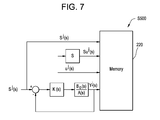
- FIG. 7 illustrates an architecture for implementing and storing results of steering tests according to an example embodiment
- FIG. 8 illustrates a method for identifying a simplified vehicle model according to an example embodiment
- FIG. 9 illustrates closed loop architecture for implementing Iterative Learning Identification (ILI) according to an example embodiment
- FIG. 10 illustrates a method for generating target poles according to an example embodiment
- FIG. 11 illustrates a method for determining calibration parameters according to an example embodiment.
- Such existing hardware may include one or more Central Processing Units (CPUs), digital signal processors (DSPs), application-specific-integrated-circuits, field programmable gate arrays (FPGAs) computers or the like.
- CPUs Central Processing Units
- DSPs digital signal processors
- FPGAs field programmable gate arrays
- tangible storage medium may be magnetic (e.g., a floppy disk or a hard drive) or optical (e.g., a compact disk read only memory, or “CD ROM”), and may be read only or random access.
- CD ROM compact disk read only memory
- FIG. 1 illustrates a system 10 in which at least one example embodiment is implemented.
- the system includes a controller 20 for implementing calibration and control of at least one vehicle system. Features of the controller 20 are described in further detail with regard to FIG. 2 .
- the system 10 further includes a steering system 30 .
- the controller 20 may be integrated into a structure of the steering system 30 in example embodiments. In at least another example embodiment, the controller 20 may be separate from the steering system 30 . It should be understood that the controller 20 may be used to control any steering system installed by a vehicle owner, dealer, or other party.
- the steering system 30 may be an electrical steering system, a drive-by-wire steering system, an electro-hydraulic steering system, or a hydraulic steering system with an electronic control interface.
- An electrical steering system or a drive-by-wire steering system may include an electric motor or actuator that is mechanically coupled to rotate or steer at least one wheel of the vehicle 60 .
- An electro-hydraulic steering system may control a hydraulic valve, a hydraulic cylinder or another hydraulic member via a solenoid or another electromechanical device to steer the vehicle 60 or execute a turn.
- the system 10 further includes a user display 40 .
- the user display 40 may display any features or parameters of the vehicle 60 , including, for example, speed and heading information.
- the user display 40 may comprise a keyboard, a keypad, a touch-screen display, a pointing device, a switch, a console, or a dashboard, for example.
- the user display 40 may be used to enter user preference parameters described in further detail below.
- the system 10 further includes a location-determining receiver 50 to determine the position of the vehicle 60 .
- the location-determining receiver may be, for example, a Global Positioning System (GPS) receiver.
- GPS Global Positioning System
- the location-determining receiver 50 may provide one or more of the following data types: position data (e.g., expressed as geographic coordinates), velocity data, and acceleration data.
- Velocity data further comprises speed data and heading data for the vehicle 60 .
- the aforementioned data may further be displayed on the user display 40 .
- the system 10 further includes at least one wheel angle sensor 70 measuring the steering angle of at least one wheel 80 .
- the lines that are interconnecting the aforementioned devices may be physical data paths, logical data paths, or both. Physical data paths are defined by transmission lines or data buses. Data buses may be, for example, Control Area Network (CAN) buses. Logical data paths may comprise logical or virtual communications that take place within software or between software modules.
- CAN Control Area Network
- FIG. 2 illustrates an example embodiment of the controller 20 .
- the controller 20 includes a data interface 200 for interfacing with other systems of the vehicle 60 .
- the data interface 200 communicates over a data bus connected to the user display 40 and/or to the location-determining receiver 50 and/or the wheel angle sensor 70 .
- the data interface 200 may connect to other devices or sensors of the vehicle including, for example, electronic control units (ECU's), which may include, for example, a transmission controller 250 and an engine controller 270 . It should be understood that these examples are non-limiting and there may be any number of controllers and/or sensors providing data to the data interface 200 over the data bus.
- ECU's electronice control units
- the data interface 200 may receive messages containing further data from any ECU such as, for example, the transmission controller 250 , engine controller 270 or other controller of the vehicle connected on the data bus.
- the messages may be implemented using a protocol such as, for example, Control Area Network (CAN).
- CAN Control Area Network
- the messages may contain data including operational parameters or other parameters related to the vehicle 60 provided by, for example, temperature gauges, magnetic wheel speed sensors, traction control sensors, etc.
- the data interface 200 relays data to or from the processor 210 and at least one memory 220 .
- the processor 210 implements algorithms and other functionality of the controller 20 described in further detail below.
- the processor 210 may be any type of processor configured to execute program codes stored in the at least one memory 210 .
- the memory 210 may be any type of memory such as Random-Access Memory (RAM) and/or Read-Only Memory (ROM), for example.
- RAM Random-Access Memory
- ROM Read-Only Memory
- the processor 210 outputs results of algorithms and other functionality of the controller 20 to the control interface 230 .
- the processor 210 may send an analog control signal or a digital control signal to the control interface 230 .
- the control interface 230 provides the signals to steering control 240 .
- the control interface 230 may provide signals including CAN messages to a steering control 240 .
- the messages may include, for example, commands such as steering angle commands or position data.
- the steering control 240 may be a motor, for example, a servo motor.
- the steering control 240 may be incorporated in a housing attached to the steering wheel 30 and the steering control 240 may be coupled to the steering wheel 30 such that the controller 20 controls operation of the steering wheel 30 and thus steering of the vehicle through the steering control 240 .
- the controller 20 may also be incorporated in this housing.
- the steering control 240 may include valves, for example hydraulic valves, for causing movement of at least one vehicle wheel 80 , and the control interface 230 provides an electrical current for operating the valves. In at least this embodiment, the steering control 240 is not incorporated in the housing of the steering wheel 30 .
- controller 20 may provide control outputs through a control interface 230 to other types of vehicle systems such as, for example, a braking system.
- Example embodiments are not limited to providing control of a steering system 30 .
- a mathematical model may be developed to describe the motion of vehicles.
- a typical vehicle model for describing vehicle motion can be expressed using a fourth-order transfer function from a front wheel steering angle, u(s), to a lateral output, y(s).
- a transfer function is a mathematical expression relating the input to the output of a system.
- a pole of a transfer function is a value at which the transfer function equals infinity. In other words, a pole is a value for which the denominator of the transfer function is zero.
- a zero of a transfer function is a value at which the transfer function equals zero. In other words, a zero is a value for which the numerator of the transfer function is zero.
- the order of a transfer function equals the number of poles of the transfer function.
- the fourth-order transfer function may be developed using vehicle parameters such as, for example, longitudinal velocity, vehicle mass, and center of gravity.
- a vehicle model G(s), calculated using typical values for the aforementioned vehicle parameters, may be expressed as:
- G ⁇ ( s ) 62.3202 ⁇ ( s + 8.3455 ) ⁇ ( s + 1.7497 ) s 2 ⁇ ( s + 39.2902 ) ⁇ ( s + 10.8859 ) ( 2 )
- s is a complex frequency variable.
- the calculation steps are known and are omitted for brevity. As can be seen, there are four poles in the model above (the s 2 term counts as two poles) and therefore the transfer function is a fourth-order transfer function.
- b 1 and b 0 are positive constants that may depend on the vehicle parameters and operating conditions.
- the model may be expressed as:
- a root locus plot of a typical fourth order model and a root locus plot of the simplified second order model are depicted and compared in FIG. 3 .
- the controller 20 controls an automated steering system for an off-road vehicle, for example, by implementing a method illustrated in FIG. 5 .
- step S 500 steering tests are conducted. A depiction of a steering test is shown in FIG. 6 .
- the steering test may include steering vehicle 60 in a defined course in a work area 600 .
- the course includes changing from a first path 610 to a second path 620 , where the first path 610 and the second path 620 are spaced apart laterally.
- the control architecture for the steering test S 500 is described with respect to FIG. 7 .
- the processor 210 chooses a reference signal s(s).
- s(s) is a step lateral signal with amplitude of, for example, 3 meters, equivalent to a crop row change such as would occur during a steering test described with respect to step S 500 and FIG. 6 .
- the processor 210 injects the reference signal Sj(s) into the closed loop architecture shown in FIG. 7 .
- the block K(s) corresponds to the compensator of the steering control system for controlling lane changes during the steering tests of step S 500 .
- the steering test provides, for example, measurements of at least one steered wheel angle u j (s) provided by at least one wheel angle sensor 70 and at least one tractor lateral position y j (s) provided by the location-determining receiver 50 .
- the processor 210 captures values during the steering test of step S 500 and writes the values to memory 220 .
- the reference signal Sj(s) may be the same as the step lateral signal s(s) discussed above.
- B 0 ⁇ ( s ) A ⁇ ( s ) in FIG. 7 represents the true plant or the true (actual) vehicle response.
- Inclusion of the transfer function block in FIG. 7 illustrates that, during the steering tests in the field 600 , the processor 210 measures and records true values of u(s), i.e., the steering angle, and the actual response y(s), i.e., the vehicle lateral position. The processor 210 therefore writes captured values for steering angle u(s), steered wheel angle rate su j (s) and lateral position y(s), captured during the steering test, to memory 220 .
- the processor 210 uses the actual measurement data, taken during the steering test of step S 500 and stored in the memory 220 , in subsequent steps illustrated in FIG. 5 , described below.
- the processor 210 uses the measurement data in the ILI algorithm step S 510 , described below, to generate a simplified vehicle model.
- Step S 510 performs system identification, in other words, in step S 510 , the processor 210 fits a mathematical model to the actual measurement data in order to perform a system identification.
- step S 510 the processor 210 generates a simplified vehicle model by identifying estimates of b 1 and b 0 from the model of Equation (3), through an iterative learning process known as Iterative Learning Identification (ILI).
- ILI Iterative Learning Identification
- b 0 0 and b 1 0 are the unknown true parameters of the system, whose values are to be estimated.
- the steered wheel angle is u(s) and the tractor lateral position is y(s).
- step S 510 The goal of the iterative learning process of step S 510 is to find acceptable estimates of B 0 (s), expressed in Equation (4), based on the measurements of the input and output data.
- Equation (5) The values of the parameter set ⁇ circumflex over ( ⁇ ) ⁇ j , ⁇ circumflex over (b) ⁇ 0 j , ⁇ circumflex over (b) ⁇ 1 j , are then used in Equation (5) to determine the estimator
- Step S 510 is described in further detail below with regard to FIGS. 8 and 9 .
- the processor 210 calculates, in step S 810 error signal ⁇ j (s) reflecting the errors between the estimated and measured values of B0(s) using the closed loop architecture according to FIG. 9 .
- the error signal ⁇ j (s) is generated if the estimation of ⁇ circumflex over (B) ⁇ j (s) is known.
- uj(s) and yj(s) are steered wheel angle and vehicle lateral output measurements, respectively, recorded during the steering test corresponding to the j-th trial in step S 500 and stored in memory 220 .
- the result is an estimated output ⁇ j (s) ⁇ A0 is the known denominator of the plant model.
- the error signal, e j (s) is from the S 810 step in FIG. 8 .
- the corrector function updates the coefficients of ⁇ circumflex over (B) ⁇ j+1 (s) for the next iteration based on the current iteration's coefficients, ⁇ circumflex over (B) ⁇ j (s) and the error signal ⁇ j (s).
- the processor 210 outputs the simplified vehicle model in S 830 as set forth in Eq. (4) in at least one example embodiment.
- the criterion for outputting the simplified model may be based on the number of iterations attained.
- the criteria may be a combination of the estimation error being below a threshold and a certain number of iterations being executed.
- ⁇ j is a projection of ⁇ j onto a finite-dimensional subspace, which has the same dimension as the unknown parameter set ⁇ circumflex over ( ⁇ ) ⁇ j
- H is a learning gain
- the matrix M can be estimated without knowing the dynamics of the feedback control algorithm, and this must be done prior to the ILI procedure.
- the measured system input, or the steered wheel angle u(s) is given by:
- u ⁇ ( s ) K ⁇ ( s ) 1 + K ⁇ ( s ) ⁇ B 0 ⁇ ( s )
- a ⁇ ( s ) ⁇ s ⁇ ( s ) G s ⁇ K ⁇ ( s ) ⁇ s ⁇ ( s ) ( 10 )
- su ⁇ ( s ) sK ⁇ ( s ) 1 + K ⁇ ( s ) ⁇ B 0 ⁇ ( s )
- a ⁇ ( s ) ⁇ s ⁇ ( s ) sG s ( K ⁇ ( s ) ⁇ s ⁇ ( s ) ( 11 )
- the two unknown terms in matrix M are estimated over the time window [0,T].
- the learning gain H can be determined based on the estimated M matrix.
- step S 520 determines desired closed-loop pole locations in step S 520 , to be implemented based on the limitations of the tractor system 10 . It will be understood, however, that in example embodiments step S 520 may occur separately from steps S 510 , S 530 and S 540 . In example embodiments, step S 520 may occur in advance of steps S 510 , S 530 and S 540 .
- the processor 210 implements a composite control system comprising the simplified vehicle model identified in step S 510 and a feedback control algorithm.
- the feedback control algorithm may be the same as the feedback control algorithm K(s) described above regarding FIG. 7 in one example embodiment.
- the feedback control algorithm may be different.
- the feedback control algorithm may share a similar structure to the structure of the feedback control algorithm K(s), but with different control gains or calibration parameters.
- the feedback control algorithm is implemented as a lead/lag compensator.
- the location of poles in a control system determines the stability and performance of the resulting control system.
- certain limitations may be imposed on the control system based on parameters of the tractor system 10 .
- the processor 210 takes these limitations into account when the processor 210 determines desired closed loop pole locations in step S 520 (or generates target poles). Step S 520 is described in detail with respect to FIG. 10 .
- step S 1000 the processor 210 receives a set of transient response specifications representing limitations of the tractor system 10 .
- limitations of the tractor system 10 For example, there may be system delays, or slow sampling rates imposed by constraints of data buses within the system 10 . These limitations may affect closed loop performance.
- a typical set of transient response specifications may include settling times and overshoot.
- an example embodiment may exhibit a settling time t x of 10 sec, and a maximum percentage of overshoot M P of 10%. These may be expressed as shown below:
- t s 4 ⁇ ⁇ ⁇ w n ⁇ ( 2 ⁇ % ⁇ ⁇ criteria ) ( 22 )
- M p e - ( ⁇ / 1 - ⁇ 2 ) ⁇ ⁇ ( 23 ) where ⁇ is the system damping ratio and w n is the system natural frequency.
- the processor 210 calculates the locations of desired closed loop poles 5520 based on these specifications.
- the vehicle dynamics model is a second order transfer function.
- the processor 210 may implement a first-order control algorithm with one closed loop pole. Therefore, the composite system includes three closed loop poles.
- the processor 210 calculates S 1010 the two dominant (i.e., lower-frequency) closed loop poles based upon the specifications, shown for example in Equations (22) and (23).
- the processor 210 determines 51020 one non-dominant pole. If the non-dominant pole is not specified, the location of this non-dominant pole may negatively affect the overall system performance. In an example embodiment, the non-dominant pole is placed at a position that is 5 times faster than the dominant closed loop poles.
- the processor 210 may also receive in step S 1030 user preference criteria and adjust the target poles based upon these preferences.
- a user may, for example, prefer a more aggressive response.
- the user may indicate that fast response time is relatively more important to the customer than smoother steering, or vice versa.
- the processor 210 may, for example, empirically decrease (override) the specified target settling time used to compute desired pole locations.
- the processor 210 may compute pole locations for nominal performance specifications and empirically adjust the resultant target pole locations.
- the processor 210 may retain the nominal settling time, the resulting nominal target pole locations, and the resulting nominal gain values that result in poles being placed at the nominal target location, but empirically adjust the resultant gains before use in the steering controller. It should be understood, however, that these are only three possible examples.
- the processor 210 determines in step S 530 calibration parameters to place the composite system poles at the target closed loop pole locations calculated in step S 520 .
- the processor 210 places the closed loop poles at the target closed loop pole locations by solving closed loop characteristic equations. It should be understood that other example embodiments may use different methods including but not limited to, for example, root locus design and the state space method. Step S 530 is described in detail with respect to FIG. 11 .
- step S 1100 of FIG. 11 the processor 210 discretizes the vehicle system model as describe below with respect to Equations (27)-(30).
- the composite system includes the identified simplified vehicle model, and a control algorithm, the control algorithm being for example a lead/lag compensator.
- a lead/lag compensator can be denoted by the following expression:
- Equation (29) The processor 210 uses zero-order hold (ZOH), for example, to transform the design from Laplace domain to z-domain, and Equation (29) shows the transformation:
- Equation (31) the composite closed loop system transfer function depicted in Equation (31) and also referred to more generically as the composite system.
- the model of equation (31) is used to calculate the control system gains for the controller 20 on the vehicle system 10 .
- the gain is equivalent to a sensitivity of a control system.
- a large correction is generated for a given error.
- a small correction would be generated for a given error.
- the gain of the controller may be adjusted based on a user preference to obtain more or less sensitive steering controls.
- a desired vehicle trajectory is provided by a field map.
- the field map is incorporated in the user display 40 in at least one example embodiment.
- GPS system 50 provides a true position of the vehicle. Based on the true position and desired position, a tracking error is input to controller 20 , and depending on the gain provided by Equation (30), corrections are made by controlling the steering of the steering mechanism 30 .
- the input to controller 20 used for steering control, are the tracking errors between the desired and actual trajectory.
- the processor 210 calculates calibration parameters S 1110 that solve the characteristic equation by setting Equation (32) equal to Equation (33). As can be seen, this will result in three equations with three unknown variables, k 1 ,k 2 ,k 3 , and the solution should be unique. This type of solution requires the least computational cost.
- the calculated calibration parameters therefore create a closed loop control system with poles placed at the desired pole locations to meet the performance criteria. Placing these calibration parameters into equation (27) results in the steering control transfer function also referred to more generically as the steering control system.
- the performance criteria may include, for example, a target settling time and a target maximum overshoot, as previously described with regard to FIG. 10 .
- performance criteria may further include target standard deviations for lateral position error and heading angle error.
- the performance criteria are satisfied if an observed settling time is less than or equal to the target settling time and an observed maximum overshoot is less than or equal to a maximum target overshoot.
- the evaluation process and the vehicle model identification includes steering vehicle 60 on a track in a defined work area, as described above with respect to FIG. 6 .
- the evaluation process may further evaluate at least an aggregate lateral position error of the steering and an aggregate heading angle error of the steering.
- the evaluating may include determining, by a location-determining receiver 50 , a plurality of pairs of actual observed positions and corresponding observed headings of the vehicle along the defined course in the work area.
- the processor 210 may then determine a lateral position error between each of the actual observed positions and a corresponding target position on the course.
- the processor 210 may further determine each heading angle error of the vehicle 60 between each of the actual observed heading angles and a target heading angle of the vehicle 60 on a course.
- the processor 210 may then estimate an aggregate lateral position error based on the determined lateral position errors.
- the processor 210 may estimate an aggregate heading error based on the determined errors.
- a GPS system 50 provides the position of the vehicle referenced to a field map. Comparing the position measurement to the desired position along a trajectory specified in the field map results in the tracking error. Namely, obtaining a difference between the two results in the tracking error TE.
- the processor 210 controls the vehicle by outputting steering commands to the steering control 240 to obtain the determined steering wheel angle. It should be noted that as the vehicle 60 is operating based on the controls of step S 540 , the user may change user preferences and control may revert to step S 520 as shown in FIG. 5 .
- step S 540 dynamic response of the vehicle 60 may be changed and the vehicle operator may subjectively determine in step S 550 , in at least one example embodiment, whether criteria are still being met.
- the operator changes an implement attached to the vehicle 60 for example, or if the operator indicates changing soil conditions for example, the operator indicates that vehicle dynamics have changed in step S 550 , re-initiation is then triggered based on new vehicle dynamics in step S 560 and the steering tests of S 500 are then performed again so that system dynamics may be re-learned.
- the processor 210 may determine, in step S 550 , whether performance criteria are still being met. After a determination that performance criteria are not being met in step S 550 , the processor 210 in step S 560 triggers re-initiation of the process starting at step S 500 .
- step S 500 the steering tests then take place again to capture new measurement data under the new vehicle dynamics.
- the processor 210 uses the new measurement data in step S 510 , described previously, to fit a mathematical model to the new measurement data to perform an updated system identification.
- the processor 210 determines calibration parameters for the controller 20 in step S 530 .
- the vehicle 60 will then be controlled in step S 540 under the updated determined control parameters.
- the calibration process herein described may be initiated based on a user request to perform a calibration procedure.
- An example embodiment may also be initiated based on the installation of a control system 20 in a vehicle 60 , for example a steering control system.
- the processor 210 provides control based on the tracking error.
- the control system may be derived according to the above described embodiments for control based on other forms of input instead of tracking error.
- the processor 210 provides control for a steering system.
- vehicle control systems may be derived according to the above described embodiments for other types of vehicle systems.
- the inventors have developed the above model taking into account that simplified models may be possible for certain off-road vehicles.
- Example embodiments enable the possibility of simpler calculations of control algorithm gains, in turn enabling control computations to be undertaken in relatively small control units in real-time on a vehicle system.
- example embodiments provide for a better control system that may adjust for vehicle parameters, soil conditions, etc., through definition of a vehicle model, identified in an iterative learning process.
Landscapes
- Engineering & Computer Science (AREA)
- Physics & Mathematics (AREA)
- General Physics & Mathematics (AREA)
- Radar, Positioning & Navigation (AREA)
- Remote Sensing (AREA)
- Mechanical Engineering (AREA)
- Transportation (AREA)
- Combustion & Propulsion (AREA)
- Chemical & Material Sciences (AREA)
- Aviation & Aerospace Engineering (AREA)
- Automation & Control Theory (AREA)
- Theoretical Computer Science (AREA)
- General Engineering & Computer Science (AREA)
- Steering Control In Accordance With Driving Conditions (AREA)
Abstract
Description
where s is a complex frequency variable. The calculation steps are known and are omitted for brevity. As can be seen, there are four poles in the model above (the s2 term counts as two poles) and therefore the transfer function is a fourth-order transfer function.
where b1 and b0 are positive constants that may depend on the vehicle parameters and operating conditions. For example, using typical vehicle parameter values mentioned above, the model may be expressed as:
in
where b0 0 and b1 0 are the unknown true parameters of the system, whose values are to be estimated. For the agricultural vehicle tested, the steered wheel angle is u(s) and the tractor lateral position is y(s). The denominator and numerator of the system at the j-th trial are defined as:
A(s)=s 2 and {circumflex over (B)} j(s)={circumflex over (b)} 0 j +{circumflex over (b)} 1 j s (5)
{circumflex over (γ)}j =[{circumflex over (b)} 0 j ,{circumflex over (b)} 1 j]T (6)
which is the estimated plant model from the j-th trial. As stated above, the goal of the ILI process is to find the real (non-estimated) plant model, and because A(s) is known the final goal will find the real (non-estimated) Bj(s). Step S510 is described in further detail below with regard to
εj(s)=[ŷ j(s)−y j(s)]A(s) (7)
{circumflex over (γ)}j+1={circumflex over (γ)}j +Hδ j (8)
H=k*M −1,(k<1) (9)
M=U T [G s(s)K(s)s(s)s(G s(s)K(s)s(s)]
where ξ is the system damping ratio and wn is the system natural frequency. The
s 1,2=−0.4±0.5458i (24)
The non-dominant closed loop pole should be placed at
s 3=−2 (25)
z=e sT
Thus, the
There are three unknown parameters in the compensator, k1,k2,k3. The identified vehicle system model described previously may be expressed as:
The
where
is the shorthand expression for
and Z{•}, L{•} denote the z and Laplace transforms respectively. By applying the transform shown in Equations (28) and (29), the discretized vehicle system model can be written as:
(z 2−2z+1)(z−k 3)+(b z1 z−b z0)(k 1 z−k 2)=0 (32)
(z−z 1)(z−z 2)(z−z 3)=0 (33)
u=TE*K(z) (34)
where K(z) is the steering control system (e.g., equation (27) with the calibration parameters plugged in.
Claims (17)
Priority Applications (2)
| Application Number | Priority Date | Filing Date | Title |
|---|---|---|---|
| US13/601,691 US9139222B2 (en) | 2012-03-30 | 2012-08-31 | Self tuning universal steering control system, method, and apparatus for off-road vehicles |
| US14/609,106 US9242671B2 (en) | 2012-03-30 | 2015-01-29 | Self tuning universal steering control system, method, and apparatus for off-road vehicles |
Applications Claiming Priority (2)
| Application Number | Priority Date | Filing Date | Title |
|---|---|---|---|
| US201261617913P | 2012-03-30 | 2012-03-30 | |
| US13/601,691 US9139222B2 (en) | 2012-03-30 | 2012-08-31 | Self tuning universal steering control system, method, and apparatus for off-road vehicles |
Related Child Applications (1)
| Application Number | Title | Priority Date | Filing Date |
|---|---|---|---|
| US14/609,106 Division US9242671B2 (en) | 2012-03-30 | 2015-01-29 | Self tuning universal steering control system, method, and apparatus for off-road vehicles |
Publications (2)
| Publication Number | Publication Date |
|---|---|
| US20130261897A1 US20130261897A1 (en) | 2013-10-03 |
| US9139222B2 true US9139222B2 (en) | 2015-09-22 |
Family
ID=48014314
Family Applications (2)
| Application Number | Title | Priority Date | Filing Date |
|---|---|---|---|
| US13/601,691 Active 2033-05-29 US9139222B2 (en) | 2012-03-30 | 2012-08-31 | Self tuning universal steering control system, method, and apparatus for off-road vehicles |
| US14/609,106 Active US9242671B2 (en) | 2012-03-30 | 2015-01-29 | Self tuning universal steering control system, method, and apparatus for off-road vehicles |
Family Applications After (1)
| Application Number | Title | Priority Date | Filing Date |
|---|---|---|---|
| US14/609,106 Active US9242671B2 (en) | 2012-03-30 | 2015-01-29 | Self tuning universal steering control system, method, and apparatus for off-road vehicles |
Country Status (4)
| Country | Link |
|---|---|
| US (2) | US9139222B2 (en) |
| DE (1) | DE112013001803T5 (en) |
| GB (1) | GB2515659B (en) |
| WO (1) | WO2013148160A2 (en) |
Cited By (2)
| Publication number | Priority date | Publication date | Assignee | Title |
|---|---|---|---|---|
| US11294043B2 (en) * | 2016-10-18 | 2022-04-05 | Hyundai Mobis Co., Ltd. | Ultrasonic sensor device and sensing method of ultrasonic sensor device |
| US12016257B2 (en) | 2020-02-19 | 2024-06-25 | Sabanto, Inc. | Methods for detecting and clearing debris from planter gauge wheels, closing wheels and seed tubes |
Families Citing this family (5)
| Publication number | Priority date | Publication date | Assignee | Title |
|---|---|---|---|---|
| US10654520B2 (en) * | 2016-08-31 | 2020-05-19 | Deere & Company | Methods and apparatuses for disturbance and stability detection by vehicle guidance systems |
| US11054828B2 (en) * | 2017-07-17 | 2021-07-06 | Agco International Gmbh | Self-tuning vehicle guidance system |
| EP3575913B1 (en) * | 2018-05-25 | 2021-09-22 | AGCO International GmbH | Robust digital controller for skid-steer agricultural machine |
| GB2594456A (en) * | 2020-04-27 | 2021-11-03 | Caterpillar Inc | System and method for autonomous steering calibration |
| US20230134480A1 (en) * | 2021-10-28 | 2023-05-04 | Magna Electronics Inc. | Vehicular control system with enhanced lane centering |
Citations (15)
| Publication number | Priority date | Publication date | Assignee | Title |
|---|---|---|---|---|
| US4811025A (en) * | 1984-12-06 | 1989-03-07 | Toyota Jidosha Kabushiki Kaisha | Automotive antenna system |
| US5593551A (en) * | 1993-05-05 | 1997-01-14 | Varian Associates, Inc. | Magnetron sputtering source for low pressure operation |
| US20020022916A1 (en) * | 2000-05-26 | 2002-02-21 | Aisin Seiki Kabushiki Kaisha | Rear-wheel steering angle control device |
| US20020040269A1 (en) * | 2000-09-29 | 2002-04-04 | Bayerische Motoren Werke Aktiengesellschaft | Control system and method using an electronic control unit for wheel-specific braking torque control |
| US20030128182A1 (en) * | 2001-10-01 | 2003-07-10 | Max Donath | Virtual mirror |
| DE10254392A1 (en) | 2002-11-18 | 2004-05-27 | Volkswagen Ag | Regulating vehicle dynamics involves detecting variable system parameter deviation from base value, identifying system parameter, determining identified system model, adapting control gain to model |
| US20080091343A1 (en) * | 2006-08-23 | 2008-04-17 | Hill Donald J | Control unit for off-road vehicles including housing configured to fit within pre-existing cavity of off-road-vehicle cab |
| EP1916584A2 (en) | 2006-10-27 | 2008-04-30 | CNH Belgium N.V. | Nudge compensation for curved swath paths |
| US20080249690A1 (en) * | 2007-04-03 | 2008-10-09 | Denso Corporation | Vehicle control system |
| US20090284208A1 (en) * | 2005-06-17 | 2009-11-19 | Mitsubishi Electric Corporation | Machine position control device |
| US20090299573A1 (en) * | 2008-05-27 | 2009-12-03 | Sebastian Thrun | Systems, methods and devices for adaptive steering control of automotive vehicles |
| US20100023222A1 (en) * | 2008-07-22 | 2010-01-28 | Trimble Navigation Limited | System and Method for Location Based Guidance Controller Configuration |
| US20100100295A1 (en) * | 2007-04-27 | 2010-04-22 | Toyota Jidosha Kabushiki Kaisha | Vehicle speed control system and vehicle speed control method of vehicle |
| US20120070013A1 (en) * | 2009-05-28 | 2012-03-22 | Ixmotion | Method and device for narrow-band noise suppression in a vehicle passenger compartment |
| US20130179036A1 (en) * | 2012-01-11 | 2013-07-11 | GM Global Technology Operations LLC | Lane tracking system with active rear-steer |
-
2012
- 2012-08-31 US US13/601,691 patent/US9139222B2/en active Active
-
2013
- 2013-03-12 WO PCT/US2013/030503 patent/WO2013148160A2/en active Application Filing
- 2013-03-12 DE DE201311001803 patent/DE112013001803T5/en active Pending
- 2013-03-12 GB GB1411999.4A patent/GB2515659B/en active Active
-
2015
- 2015-01-29 US US14/609,106 patent/US9242671B2/en active Active
Patent Citations (15)
| Publication number | Priority date | Publication date | Assignee | Title |
|---|---|---|---|---|
| US4811025A (en) * | 1984-12-06 | 1989-03-07 | Toyota Jidosha Kabushiki Kaisha | Automotive antenna system |
| US5593551A (en) * | 1993-05-05 | 1997-01-14 | Varian Associates, Inc. | Magnetron sputtering source for low pressure operation |
| US20020022916A1 (en) * | 2000-05-26 | 2002-02-21 | Aisin Seiki Kabushiki Kaisha | Rear-wheel steering angle control device |
| US20020040269A1 (en) * | 2000-09-29 | 2002-04-04 | Bayerische Motoren Werke Aktiengesellschaft | Control system and method using an electronic control unit for wheel-specific braking torque control |
| US20030128182A1 (en) * | 2001-10-01 | 2003-07-10 | Max Donath | Virtual mirror |
| DE10254392A1 (en) | 2002-11-18 | 2004-05-27 | Volkswagen Ag | Regulating vehicle dynamics involves detecting variable system parameter deviation from base value, identifying system parameter, determining identified system model, adapting control gain to model |
| US20090284208A1 (en) * | 2005-06-17 | 2009-11-19 | Mitsubishi Electric Corporation | Machine position control device |
| US20080091343A1 (en) * | 2006-08-23 | 2008-04-17 | Hill Donald J | Control unit for off-road vehicles including housing configured to fit within pre-existing cavity of off-road-vehicle cab |
| EP1916584A2 (en) | 2006-10-27 | 2008-04-30 | CNH Belgium N.V. | Nudge compensation for curved swath paths |
| US20080249690A1 (en) * | 2007-04-03 | 2008-10-09 | Denso Corporation | Vehicle control system |
| US20100100295A1 (en) * | 2007-04-27 | 2010-04-22 | Toyota Jidosha Kabushiki Kaisha | Vehicle speed control system and vehicle speed control method of vehicle |
| US20090299573A1 (en) * | 2008-05-27 | 2009-12-03 | Sebastian Thrun | Systems, methods and devices for adaptive steering control of automotive vehicles |
| US20100023222A1 (en) * | 2008-07-22 | 2010-01-28 | Trimble Navigation Limited | System and Method for Location Based Guidance Controller Configuration |
| US20120070013A1 (en) * | 2009-05-28 | 2012-03-22 | Ixmotion | Method and device for narrow-band noise suppression in a vehicle passenger compartment |
| US20130179036A1 (en) * | 2012-01-11 | 2013-07-11 | GM Global Technology Operations LLC | Lane tracking system with active rear-steer |
Non-Patent Citations (2)
| Title |
|---|
| International Search Report and Written Opinion dated Apr. 17, 2014. |
| PCT International Preliminary Report on Patentability and Written Opinion for corresponding International Application No. PCT/US2013/030503 dated Oct. 9, 2014. |
Cited By (2)
| Publication number | Priority date | Publication date | Assignee | Title |
|---|---|---|---|---|
| US11294043B2 (en) * | 2016-10-18 | 2022-04-05 | Hyundai Mobis Co., Ltd. | Ultrasonic sensor device and sensing method of ultrasonic sensor device |
| US12016257B2 (en) | 2020-02-19 | 2024-06-25 | Sabanto, Inc. | Methods for detecting and clearing debris from planter gauge wheels, closing wheels and seed tubes |
Also Published As
| Publication number | Publication date |
|---|---|
| GB201411999D0 (en) | 2014-08-20 |
| US20150142270A1 (en) | 2015-05-21 |
| US20130261897A1 (en) | 2013-10-03 |
| US9242671B2 (en) | 2016-01-26 |
| GB2515659B (en) | 2019-05-01 |
| WO2013148160A2 (en) | 2013-10-03 |
| WO2013148160A3 (en) | 2014-05-30 |
| DE112013001803T5 (en) | 2014-12-24 |
| GB2515659A (en) | 2014-12-31 |
Similar Documents
| Publication | Publication Date | Title |
|---|---|---|
| US9242671B2 (en) | Self tuning universal steering control system, method, and apparatus for off-road vehicles | |
| Kayacan et al. | Towards agrobots: Identification of the yaw dynamics and trajectory tracking of an autonomous tractor | |
| US20180308296A1 (en) | Emulator hardware-in-loop architecture and control logic for vehicle steer-by-wire test system | |
| CN107380254B (en) | Electric power steering control using system state prediction | |
| US20150134181A1 (en) | Position estimation and vehicle control in autonomous multi-vehicle convoys | |
| US10340828B2 (en) | Disturbance observer for permanent magnet direct current machines | |
| CN110816528A (en) | Solver for embedded real-time constrained optimal control problem in autonomous system | |
| CN110968088B (en) | Method and device for determining vehicle control parameters, vehicle-mounted controller and unmanned vehicle | |
| EP3442840B1 (en) | Device for tracking the path of a vehicle | |
| EP2669146A2 (en) | Average friction learning and average friction change estimation | |
| CN112146561B (en) | Hall angle sensor installation angle offset estimation method | |
| EP4345421A2 (en) | Method for calibrating sensor parameters based on autonomous driving, apparatus, storage medium, and vehicle | |
| US11827293B2 (en) | Real-time estimation of achievable angle, velocity, and acceleration capabilities of steering actuator | |
| CN112298354A (en) | State estimation method for steering wheel and front wheel corner of steering system of unmanned automobile | |
| Ge et al. | Robust adaptive sliding mode control for path tracking of unmanned agricultural vehicles | |
| US11235802B2 (en) | Enhanced vehicle operation | |
| CN114115274A (en) | Agricultural wheeled tractor path tracking output feedback control strategy | |
| Rödönyi et al. | Identification of the nonlinear steering dynamics of an autonomous vehicle | |
| Karkee et al. | Parameter estimation and validation of a tractor and single axle towed implement dynamic system model | |
| CN112147656B (en) | GNSS double-antenna course installation angle offset estimation method | |
| CN112758109B (en) | Transverse tracking steady state deviation compensation method and device | |
| CN109283923A (en) | A kind of modeling of tractor self-steering system | |
| CN110995203A (en) | Nonlinear observability degree analysis method based on condition number fusion | |
| RU2821391C1 (en) | Wheel odometry sensors calibration method | |
| Malonga Makosi et al. | Advanced model-based control functions to design the longitudinal vehicle dynamics in passenger cars |
Legal Events
| Date | Code | Title | Description |
|---|---|---|---|
| AS | Assignment |
Owner name: DEERE & COMPANY, ILLINOIS Free format text: ASSIGNMENT OF ASSIGNORS INTEREST;ASSIGNORS:POTTER, MATTHEW D.;SCHLEICHER, TYLER D.;LIU, NANJUN;AND OTHERS;SIGNING DATES FROM 20120814 TO 20120820;REEL/FRAME:028923/0517 |
|
| STCF | Information on status: patent grant |
Free format text: PATENTED CASE |
|
| MAFP | Maintenance fee payment |
Free format text: PAYMENT OF MAINTENANCE FEE, 4TH YEAR, LARGE ENTITY (ORIGINAL EVENT CODE: M1551); ENTITY STATUS OF PATENT OWNER: LARGE ENTITY Year of fee payment: 4 |
|
| MAFP | Maintenance fee payment |
Free format text: PAYMENT OF MAINTENANCE FEE, 8TH YEAR, LARGE ENTITY (ORIGINAL EVENT CODE: M1552); ENTITY STATUS OF PATENT OWNER: LARGE ENTITY Year of fee payment: 8 |