JP4938541B2 - Console box bottom mounting structure - Google Patents
Console box bottom mounting structure Download PDFInfo
- Publication number
- JP4938541B2 JP4938541B2 JP2007117836A JP2007117836A JP4938541B2 JP 4938541 B2 JP4938541 B2 JP 4938541B2 JP 2007117836 A JP2007117836 A JP 2007117836A JP 2007117836 A JP2007117836 A JP 2007117836A JP 4938541 B2 JP4938541 B2 JP 4938541B2
- Authority
- JP
- Japan
- Prior art keywords
- cut
- support bracket
- console box
- box
- raised
- Prior art date
- Legal status (The legal status is an assumption and is not a legal conclusion. Google has not performed a legal analysis and makes no representation as to the accuracy of the status listed.)
- Expired - Fee Related
Links
- 239000011324 bead Substances 0.000 description 2
- 230000003014 reinforcing effect Effects 0.000 description 2
- 238000010521 absorption reaction Methods 0.000 description 1
- 239000002184 metal Substances 0.000 description 1
- 238000012986 modification Methods 0.000 description 1
- 230000004048 modification Effects 0.000 description 1
- 239000011347 resin Substances 0.000 description 1
- 229920005989 resin Polymers 0.000 description 1
Images


Landscapes
- Vehicle Step Arrangements And Article Storage (AREA)
Description
この発明は、コンソールボックス底部取付部構造に関するものである。 The present invention relates to a console box bottom mounting portion structure.
自動車などの車両には、車室内の運転席と助手席との間の部分に、ほぼ車両前後方向へ延びるセンターコンソールを備えたものが存在する(例えば、特許文献1参照)。 Some vehicles such as automobiles are provided with a center console extending in the vehicle front-rear direction at a portion between a driver seat and a passenger seat in a passenger compartment (see, for example, Patent Document 1).
そして、図3に示すように、センターコンソール1の後部には、通常、コンソールボックス2などが設けられている。このコンソールボックス2は、図4に示すように、コンソールボックス本体3と、このコンソールボックス本体3の上部に開閉可能に設けられたリッド部4とを備えている。コンソールボックス本体3は、外観部を構成するボックスアウタ部5と、このボックスアウタ部5の内部に設置されたボックス容器部6とを備えている。
As shown in FIG. 3, a
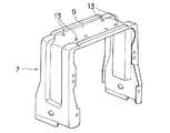
コンソールボックス2を構成するボックス容器部6の下方には、図5に示すように、正面視ほぼ下向きコ字状の支持ブラケット7が配設されている。ボックス容器部6は、この支持ブラケット7によって、底面部8を支持固定される。即ち、このボックス容器部6の底面部8と、支持ブラケット7の上面部9との間が、ネジ12で止められている。
Below the
そのために、上面部9には、ネジ孔13が形成され、ボックス容器部6の底面部8には、ネジ孔13と対応するボス部14が突設されている。上面部9には、所要の強度を有するように、エンボス加工などが適宜施されている。
For this purpose, a
なお、図3中、符号15は、センターコンソール1の後部に対して取付けられるリアカバーである。
しかしながら、上記コンソールボックス底部取付部構造では、ボックス容器部6の底面部8と、支持ブラケット7の上面部9との間を、ネジ12でほぼ直接固定するようにしていたので、緊急時に上方からの荷重入力(例えば、後席乗員の頭部の二次衝突による荷重入力など)があった場合に、これを充分に吸収することができなかった。
However, in the console box bottom mounting portion structure, since the space between the
上記課題を解決するために、請求項1に記載された発明では、コンソールボックスを構成するボックス容器部の下方に、ほぼ下向きコ字状の支持ブラケットを配設し、ボックス容器部の底面部と、支持ブラケットの上面部に設けられた取付座面との間をネジ止めしたコンソールボックス底部取付部構造において、前記取付座面を、支持ブラケットの上面部から上方へ切起し形成された切起片の先端部に設けると共に、前記切起片の根元部分に、スリット部を形成し、且つ、前記切起片およびスリット部を、緊急時の荷重入力を吸収可能な切起し高さおよび切込み深さに設定したコンソールボックス底部取付部構造を特徴としている。
In order to solve the above-mentioned problem, in the invention described in
請求項1の発明によれば、前記取付座面を、支持ブラケットの上面部から上方へ切起し形成された切起片の先端部に設けると共に、前記切起片の根元部分に、スリット部を形成し、且つ、前記切起片およびスリット部を、緊急時の荷重入力を吸収可能な切起し高さおよび切込み深さに設定したことにより、緊急時などに、切起片およびスリット部が変形することによって、上方からの荷重入力を充分に吸収することが可能となる。 According to the first aspect of the present invention, the mounting seat surface is provided at the front end portion of the cut and raised piece formed by cutting upward from the upper surface portion of the support bracket, and the slit portion is provided at the root portion of the cut and raised piece. And the cut and raised pieces and the slit portion are set to a cut and raised height and a cut depth capable of absorbing an emergency load input. By deforming, it becomes possible to sufficiently absorb the load input from above.
以下、本発明を具体化した実施例について、図示例と共に説明する。 Hereinafter, embodiments embodying the present invention will be described together with illustrated examples.
図1、図2は、この発明の実施例を示すものである。 1 and 2 show an embodiment of the present invention.
なお、センターコンソールおよびコンソールボックスの構成については、図3を用いて説明したものと基本的にほぼ同様なので、必要に応じてこの図面を参照すると共に、これに対する記載を以てこの実施例の説明とすることができる。この際、同一ないし均等な部分については、同一の符号を付すようにしている。但し、図3と異なる構成がある場合については、図1、図2に拠るものとする。 The configurations of the center console and the console box are basically the same as those described with reference to FIG. 3, so that this drawing will be referred to as necessary and the description of this embodiment will be made with reference thereto. be able to. At this time, the same or equivalent parts are denoted by the same reference numerals. However, in the case where there is a configuration different from that in FIG. 3, it is based on FIGS.
まず、構成について説明する。 First, the configuration will be described.
自動車などの車両には、車室内の運転席と助手席との間の部分に、図3に示すように、ほぼ車両前後方向へ延びるセンターコンソール1が備えられている。
A vehicle such as an automobile is provided with a
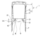
このセンターコンソール1の後部には、通常、コンソールボックス2などが設けられている。このコンソールボックス2は、図1に示すように、コンソールボックス本体3と、このコンソールボックス本体3の上部に開閉可能に設けられたリッド部4とを備えている。コンソールボックス本体3は、外観部を構成するボックスアウタ部5と、このボックスアウタ部5の内部に設置されたボックス容器部6とを備えている。
A
ボックスアウタ部5は、センターコンソール1の後部とされている。ボックス容器部6は、上面に開口部を有する箱型のものなどとされている。このボックス容器部6は、樹脂製とされている。
The box
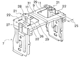
そして、コンソールボックス2を構成するボックス容器部6の下方には、図2に示すように、正面視ほぼ下向きコ字状の支持ブラケット7(ボックス底部支持ブラケット)が配設されている。この支持ブラケット7は、金属製とされている。ボックス容器部6は、この支持ブラケット7によって、底面部8を支持固定される。即ち、このボックス容器部6の底面部8と、支持ブラケット7の上面部9に設けられた取付座面11との間が、ネジ12を用いて固定されている。
As shown in FIG. 2, a U-shaped support bracket 7 (box bottom support bracket) that is substantially downward when viewed from the front is disposed below the
そのために、上面部9には、ネジ孔13が形成され、ボックス容器部6の底面部8には、ネジ孔13と対応するボス部14がほぼ下方へ向けて突設されている。
For this purpose, a
なお、図3中、符号15は、センターコンソール1の後部に対して取付けられるリアカバーである。
In FIG. 3,
以上の構成は、上記した従来例のものとほぼ同様である。 The above configuration is almost the same as that of the conventional example described above.
以上のような基本構成に対し、この実施例のものでは、取付座面11を、支持ブラケット7の上面部9から上方へ切起し形成された切起片21の先端部に設けるようにする。この切起片21は、左右一対設けられている。
In contrast to the basic configuration as described above, in this embodiment, the
また、各切起片21の根元部分に、スリット部22を形成する。スリット部22は、切起片21の根元部分の両側部に、ほぼ均等な長さで前後一対設けるようにするのが好ましい。このスリット部22は、切起片21の切り起し方向に沿ったものなどとする。この場合には、スリット部22は、車幅方向へ延びるものとされている。
In addition, a
且つ、切起片21およびスリット部22を、緊急時の荷重入力を吸収可能な切起し高さ24(切起片21)および切込み深さ25(スリット部22)に設定する。
Further, the cut and raised
この切起片21の部分は、その上端側に、内方へ向けてほぼ水平に延びる取付座面11を有し、その中間部に、取付座面11の外側辺部から下方へ向けてほぼ垂直に延びる縦面部26を有し、その下端側に、縦面部26の下辺部から外方へ向けてスリット部22の長さだけほぼ水平に延びる下面部27を有する、正面視ほぼクランク形状のものなどとなる。
The cut-and-raised
なお、この切起片21に対し、必要に応じて、ほぼ上下方向へ延びる補強ビードなどの切起片強度調節形状部28を設けるようにしても良い。この場合、切起片強度調節形状部28は、切起片21の縦面部26から下面部27にかけて形成されている。
The cut and raised
また、図中、符号29は、切起片21を形成したことにより、支持ブラケット7の上面部9に形成された穴部である。この穴部29により、支持ブラケット7の上面部9は、枠状となる。更に、符号31は、支持ブラケット7の上面部9に形成された補強ビードなどの上面強度調節形状部である。この上面強度調節形状部31は、左右の穴部29の中間部分に、ほぼ車両前後方向へ向けて形成されている。
In the drawing,
次に、この実施例の作用について説明する。 Next, the operation of this embodiment will be described.
コンソールボックス本体3に対してリッド部4を開くことにより、ボックス容器部6が外部に露出されるので、ボックス容器部6に対する物の出し入れが可能となる。
By opening the
反対に、コンソールボックス本体3に対してリッド部4を閉じることにより、ボックス容器部6が隠されるので、物を外部から見えないように収納しておくことが可能となる。
On the contrary, by closing the
そして、緊急時に、閉じた状態のリッド部4に上方から下方へ向かう荷重入力があった場合には、切起片21およびスリット部22が下方に変形する。この切起片21およびスリット部22の変形によって、荷重入力が吸収される。
In an emergency, when there is a load input from the upper side to the lower side in the
この荷重入力に対する吸収量は、切起片21の切起し高さ24、および、スリット部22の切込み深さ25によって設定される。この場合の、切起し高さ24および切込み深さ25は、通常の切起部の切起し高さや、通常のスリット部の切込み深さよりは大きなものとされる。この切起し高さ24および切込み深さ25は、最適なものとなるように精密に設計される。
The amount of absorption with respect to this load input is set by the cut and raised
この実施例によれば、取付座面11を、支持ブラケット7の上面部9から上方へ切起し形成された切起片21の先端部に設けると共に、切起片21の根元部分に、スリット部22を形成し、且つ、切起片21およびスリット部22を、緊急時の荷重入力を吸収可能な切起し高さ24および切込み深さ25に設定したことにより、緊急時などに、切起片21およびスリット部22が変形することによって、上方からの荷重入力を充分に吸収することが可能となる。
According to this embodiment, the mounting
以上、この発明の実施例を図面により詳述してきたが、実施例はこの発明の例示にしか過ぎないものであるため、この発明は実施例の構成にのみ限定されるものではなく、この発明の要旨を逸脱しない範囲の設計の変更等があってもこの発明に含まれることは勿論である。また、例えば、各実施例に複数の構成が含まれている場合には、特に記載がなくとも、これらの構成の可能な組合せが含まれることは勿論である。また、複数の実施例や変形例が示されている場合には、特に記載がなくとも、これらに跨がった構成の組合せのうちの可能なものが含まれることは勿論である。また、図面に描かれている構成については、特に記載がなくとも、含まれることは勿論である。 Although the embodiments of the present invention have been described in detail with reference to the drawings, the embodiments are only examples of the present invention, and the present invention is not limited to the configurations of the embodiments. Needless to say, design changes and the like within a range not departing from the gist of the invention are included in the present invention. Further, for example, when each embodiment includes a plurality of configurations, it is a matter of course that possible combinations of these configurations are included even if not specifically described. Further, when a plurality of embodiments and modifications are shown, it is needless to say that possible combinations of configurations extending over these are included even if not specifically described. Further, the configuration depicted in the drawings is of course included even if not particularly described.
2 コンソールボックス
6 ボックス容器部
7 支持ブラケット
8 底面部
9 上面部
11 取付座面
12 ネジ
21 切起片
22 スリット部
24 切起し高さ
25 切込み深さ
2
Claims (1)
前記取付座面を、支持ブラケットの上面部から上方へ切起し形成された切起片の先端部に設けると共に、
前記切起片の根元部分に、スリット部を形成し、
且つ、前記切起片およびスリット部を、緊急時の荷重入力を吸収可能な切起し高さおよび切込み深さに設定したことを特徴とするコンソールボックス底部取付部構造。 A substantially downward U-shaped support bracket is arranged below the box container part constituting the console box, and a screw is provided between the bottom surface part of the box container part and the mounting seat surface provided on the upper surface part of the support bracket. In the console box bottom mounting part structure
The mounting seat surface is provided at the tip of a cut and raised piece formed by cutting upward from the upper surface of the support bracket, and
Forming a slit in the root of the cut and raised piece;
The console box bottom mounting structure is characterized in that the cut and raised piece and the slit are set to a cut and raised height and a cut depth capable of absorbing an emergency load input.
Priority Applications (1)
| Application Number | Priority Date | Filing Date | Title |
|---|---|---|---|
| JP2007117836A JP4938541B2 (en) | 2007-04-27 | 2007-04-27 | Console box bottom mounting structure |
Applications Claiming Priority (1)
| Application Number | Priority Date | Filing Date | Title |
|---|---|---|---|
| JP2007117836A JP4938541B2 (en) | 2007-04-27 | 2007-04-27 | Console box bottom mounting structure |
Publications (2)
| Publication Number | Publication Date |
|---|---|
| JP2008273339A JP2008273339A (en) | 2008-11-13 |
| JP4938541B2 true JP4938541B2 (en) | 2012-05-23 |
Family
ID=40051885
Family Applications (1)
| Application Number | Title | Priority Date | Filing Date |
|---|---|---|---|
| JP2007117836A Expired - Fee Related JP4938541B2 (en) | 2007-04-27 | 2007-04-27 | Console box bottom mounting structure |
Country Status (1)
| Country | Link |
|---|---|
| JP (1) | JP4938541B2 (en) |
Families Citing this family (10)
| Publication number | Priority date | Publication date | Assignee | Title |
|---|---|---|---|---|
| JP5165491B2 (en) * | 2008-07-31 | 2013-03-21 | ダイキョーニシカワ株式会社 | Rear console |
| KR100944766B1 (en) | 2008-11-06 | 2010-03-03 | 한일이화주식회사 | Console bracket of vehicle |
| DE102008063665A1 (en) * | 2008-12-18 | 2010-06-24 | Euwe Eugen Wexler Gmbh | Center console of a motor vehicle |
| JP5280829B2 (en) * | 2008-12-22 | 2013-09-04 | カルソニックカンセイ株式会社 | Console shock absorber structure |
| JP5907706B2 (en) * | 2011-11-29 | 2016-04-26 | 日本プラスト株式会社 | Storage device |
| JP6094092B2 (en) | 2012-08-20 | 2017-03-15 | スズキ株式会社 | Console Box |
| JP5900302B2 (en) * | 2012-11-29 | 2016-04-06 | トヨタ自動車株式会社 | Console structure |
| CN108859983B (en) * | 2018-05-18 | 2021-03-09 | 安徽江淮汽车集团股份有限公司 | Automobile armrest box assembly |
| KR102074815B1 (en) * | 2018-09-11 | 2020-02-10 | 에코플라스틱 주식회사 | Floor console mounting structure of car |
| JP7380123B2 (en) * | 2019-11-19 | 2023-11-15 | スズキ株式会社 | Vehicle interior structure |
Family Cites Families (3)
| Publication number | Priority date | Publication date | Assignee | Title |
|---|---|---|---|---|
| JPH0614846B2 (en) * | 1985-12-26 | 1994-03-02 | 曽田香料株式会社 | Flavoring agent with milky aroma |
| JPH0210151A (en) * | 1988-06-28 | 1990-01-12 | Toshiba Corp | Magnetic flaw detector |
| JP4258437B2 (en) * | 2003-10-31 | 2009-04-30 | 豊田合成株式会社 | Console module assembly structure |
-
2007
- 2007-04-27 JP JP2007117836A patent/JP4938541B2/en not_active Expired - Fee Related
Also Published As
| Publication number | Publication date |
|---|---|
| JP2008273339A (en) | 2008-11-13 |
Similar Documents
| Publication | Publication Date | Title |
|---|---|---|
| JP4938541B2 (en) | Console box bottom mounting structure | |
| JP5692506B2 (en) | Instrument panel box support structure | |
| JP5708993B2 (en) | Vehicle door trim | |
| JP2013124069A (en) | center console | |
| JP5148870B2 (en) | Car door structure | |
| JP5280829B2 (en) | Console shock absorber structure | |
| JP2008230587A (en) | Console mounting part structure | |
| JP2008290605A (en) | Rear bumper cover structure | |
| JP2008030632A (en) | Vehicle deck garnish structure | |
| JP5614663B2 (en) | Body front structure | |
| JP5920086B2 (en) | Automotive door trim structure | |
| JP2017222320A (en) | Vehicle front structure | |
| JP5982328B2 (en) | Rear body structure of the vehicle | |
| JP2014180974A (en) | Vehicle body front structure of vehicle | |
| JP5347613B2 (en) | Auto body structure | |
| JP6024441B2 (en) | Body rear structure | |
| JP5427519B2 (en) | Vehicle door structure | |
| JP2005289250A (en) | Interior trim component for automobile | |
| JP6372735B2 (en) | Door trim structure for automobile doors | |
| JP2010058528A (en) | Lid opening/closing structure for vehicular storage part | |
| JP5023677B2 (en) | Car interior side structure | |
| JP2007196731A (en) | Structure around the glove box in the vehicle compartment | |
| JP2014012423A (en) | Attachment structure of headrest | |
| JP6348338B2 (en) | Vehicle front structure | |
| JP2007168713A (en) | Cab structure of cab over type vehicle |
Legal Events
| Date | Code | Title | Description |
|---|---|---|---|
| A621 | Written request for application examination |
Free format text: JAPANESE INTERMEDIATE CODE: A621 Effective date: 20091210 |
|
| A977 | Report on retrieval |
Free format text: JAPANESE INTERMEDIATE CODE: A971007 Effective date: 20111006 |
|
| TRDD | Decision of grant or rejection written | ||
| A01 | Written decision to grant a patent or to grant a registration (utility model) |
Free format text: JAPANESE INTERMEDIATE CODE: A01 Effective date: 20120221 |
|
| A01 | Written decision to grant a patent or to grant a registration (utility model) |
Free format text: JAPANESE INTERMEDIATE CODE: A01 |
|
| A61 | First payment of annual fees (during grant procedure) |
Free format text: JAPANESE INTERMEDIATE CODE: A61 Effective date: 20120223 |
|
| FPAY | Renewal fee payment (event date is renewal date of database) |
Free format text: PAYMENT UNTIL: 20150302 Year of fee payment: 3 |
|
| R150 | Certificate of patent or registration of utility model |
Ref document number: 4938541 Country of ref document: JP Free format text: JAPANESE INTERMEDIATE CODE: R150 Free format text: JAPANESE INTERMEDIATE CODE: R150 |
|
| R250 | Receipt of annual fees |
Free format text: JAPANESE INTERMEDIATE CODE: R250 |
|
| R250 | Receipt of annual fees |
Free format text: JAPANESE INTERMEDIATE CODE: R250 |
|
| R250 | Receipt of annual fees |
Free format text: JAPANESE INTERMEDIATE CODE: R250 |
|
| R250 | Receipt of annual fees |
Free format text: JAPANESE INTERMEDIATE CODE: R250 |
|
| LAPS | Cancellation because of no payment of annual fees |