JP4937133B2 - Tubular member cleaning scraper - Google Patents
Tubular member cleaning scraper Download PDFInfo
- Publication number
- JP4937133B2 JP4937133B2 JP2007545511A JP2007545511A JP4937133B2 JP 4937133 B2 JP4937133 B2 JP 4937133B2 JP 2007545511 A JP2007545511 A JP 2007545511A JP 2007545511 A JP2007545511 A JP 2007545511A JP 4937133 B2 JP4937133 B2 JP 4937133B2
- Authority
- JP
- Japan
- Prior art keywords
- scraper
- elastic
- tubular member
- cartridge
- pat
- Prior art date
- Legal status (The legal status is an assumption and is not a legal conclusion. Google has not performed a legal analysis and makes no representation as to the accuracy of the status listed.)
- Expired - Fee Related
Links
- 238000004140 cleaning Methods 0.000 title description 20
- 230000000712 assembly Effects 0.000 claims description 10
- 238000000429 assembly Methods 0.000 claims description 10
- 125000006850 spacer group Chemical group 0.000 claims description 7
- 239000010453 quartz Substances 0.000 description 30
- VYPSYNLAJGMNEJ-UHFFFAOYSA-N silicon dioxide Inorganic materials O=[Si]=O VYPSYNLAJGMNEJ-UHFFFAOYSA-N 0.000 description 30
- XLYOFNOQVPJJNP-UHFFFAOYSA-N water Substances O XLYOFNOQVPJJNP-UHFFFAOYSA-N 0.000 description 11
- 239000000463 material Substances 0.000 description 5
- 239000002253 acid Substances 0.000 description 4
- 229910052751 metal Inorganic materials 0.000 description 4
- 239000002184 metal Substances 0.000 description 4
- 239000004576 sand Substances 0.000 description 3
- 239000010865 sewage Substances 0.000 description 3
- 239000000126 substance Substances 0.000 description 3
- XEEYBQQBJWHFJM-UHFFFAOYSA-N Iron Chemical compound [Fe] XEEYBQQBJWHFJM-UHFFFAOYSA-N 0.000 description 2
- 239000004809 Teflon Substances 0.000 description 2
- 229920006362 Teflon® Polymers 0.000 description 2
- 239000012535 impurity Substances 0.000 description 2
- 238000010297 mechanical methods and process Methods 0.000 description 2
- 238000000034 method Methods 0.000 description 2
- 239000005416 organic matter Substances 0.000 description 2
- 239000004033 plastic Substances 0.000 description 2
- 238000002604 ultrasonography Methods 0.000 description 2
- OBMBUODDCOAJQP-UHFFFAOYSA-N 2-chloro-4-phenylquinoline Chemical compound C=12C=CC=CC2=NC(Cl)=CC=1C1=CC=CC=C1 OBMBUODDCOAJQP-UHFFFAOYSA-N 0.000 description 1
- 241000894006 Bacteria Species 0.000 description 1
- OYPRJOBELJOOCE-UHFFFAOYSA-N Calcium Chemical compound [Ca] OYPRJOBELJOOCE-UHFFFAOYSA-N 0.000 description 1
- 241000700605 Viruses Species 0.000 description 1
- 150000007513 acids Chemical class 0.000 description 1
- 238000005452 bending Methods 0.000 description 1
- 229910052791 calcium Inorganic materials 0.000 description 1
- 239000011575 calcium Substances 0.000 description 1
- 238000006243 chemical reaction Methods 0.000 description 1
- 239000011248 coating agent Substances 0.000 description 1
- 238000000576 coating method Methods 0.000 description 1
- -1 debris Substances 0.000 description 1
- 230000000249 desinfective effect Effects 0.000 description 1
- 230000007613 environmental effect Effects 0.000 description 1
- 239000012530 fluid Substances 0.000 description 1
- 238000002347 injection Methods 0.000 description 1
- 239000007924 injection Substances 0.000 description 1
- 229910010272 inorganic material Inorganic materials 0.000 description 1
- 239000011147 inorganic material Substances 0.000 description 1
- 238000007689 inspection Methods 0.000 description 1
- 229910052742 iron Inorganic materials 0.000 description 1
- JEIPFZHSYJVQDO-UHFFFAOYSA-N iron(III) oxide Inorganic materials O=[Fe]O[Fe]=O JEIPFZHSYJVQDO-UHFFFAOYSA-N 0.000 description 1
- 238000003754 machining Methods 0.000 description 1
- WPBNNNQJVZRUHP-UHFFFAOYSA-L manganese(2+);methyl n-[[2-(methoxycarbonylcarbamothioylamino)phenyl]carbamothioyl]carbamate;n-[2-(sulfidocarbothioylamino)ethyl]carbamodithioate Chemical compound [Mn+2].[S-]C(=S)NCCNC([S-])=S.COC(=O)NC(=S)NC1=CC=CC=C1NC(=S)NC(=O)OC WPBNNNQJVZRUHP-UHFFFAOYSA-L 0.000 description 1
- 238000004519 manufacturing process Methods 0.000 description 1
- 244000005700 microbiome Species 0.000 description 1
- 238000006552 photochemical reaction Methods 0.000 description 1
- 238000001556 precipitation Methods 0.000 description 1
- 230000001737 promoting effect Effects 0.000 description 1
- 230000001681 protective effect Effects 0.000 description 1
- 239000005060 rubber Substances 0.000 description 1
- 239000000523 sample Substances 0.000 description 1
- 229910001220 stainless steel Inorganic materials 0.000 description 1
- 239000010935 stainless steel Substances 0.000 description 1
- 230000001954 sterilising effect Effects 0.000 description 1
- 238000004506 ultrasonic cleaning Methods 0.000 description 1
- 239000002351 wastewater Substances 0.000 description 1
- 210000002268 wool Anatomy 0.000 description 1
Images


Classifications
-
- B—PERFORMING OPERATIONS; TRANSPORTING
- B08—CLEANING
- B08B—CLEANING IN GENERAL; PREVENTION OF FOULING IN GENERAL
- B08B9/00—Cleaning hollow articles by methods or apparatus specially adapted thereto
- B08B9/02—Cleaning pipes or tubes or systems of pipes or tubes
- B08B9/023—Cleaning the external surface
-
- B08B1/165—
-
- B08B1/30—
-
- C—CHEMISTRY; METALLURGY
- C02—TREATMENT OF WATER, WASTE WATER, SEWAGE, OR SLUDGE
- C02F—TREATMENT OF WATER, WASTE WATER, SEWAGE, OR SLUDGE
- C02F1/00—Treatment of water, waste water, or sewage
- C02F1/30—Treatment of water, waste water, or sewage by irradiation
- C02F1/32—Treatment of water, waste water, or sewage by irradiation with ultraviolet light
Description
【技術分野】
【0001】
本発明は、概して、スケール(scale)、錆、有機付着物、及び無機付着物を管状部材の外面から取り除く装置の改良に関している。本発明は、より詳細には、流体の殺菌及び光化学反応の発生に使用される紫外線ランプを収納する石英スリーブの外側表面を掃除する装置の目詰まりを低減する装置に関する。
【背景技術】
【0002】
有害なバクテリアやウイルスを含む可能性のある水を処理するために紫外線(UV)ランプが使用された最初の時期に、ランプの外側表面に、水中の不純物が被覆することが知られていた。例えば、UVランプが水中に沈められている場合、保護用の石英スリーブ内にあるUVランプの大部分は水に入ってしまう。このような種類のUVランプは、ランプの種類に応じて、40℃から800℃の表面温度で動作する。水は、カルシウム、マンガン、及び鉄などの不純物を含んでおり、それらは、石英スリーブに収納されているランプにより生じる熱によって、石英スリーブの表面上に析出してしまう。このような析出によって、水を殺菌する又は化学反応を促進する紫外線が水に届くことが妨げられてしまう。物質の積み重なりが非常に顕著になると、全ての紫外線が吸収されて、ランプで生成された紫外線以外の波長の光が、石英スリーブの外側表面の微生物の成長を促進してしまう。石英スリーブ上のこのようなコーティングによって、ある種の面内(in-plane)掃除システムや、UVユニットを分離及び分解して手作業で掃除することが必要とされる。UVランプを囲う石英管の掃除は、このような機器を製造する主要な機会となってきた。様々なスクレーパ、ブラシ、超音波洗浄、面内酸洗浄、空気洗浄、及び化学物質が、この問題を解決するために提案されてきた。
【0003】
従来のスクレーパ又はワイパは、通常、フェルト、ゴム、金属、プラスチック又はテフロン(登録商標)で形成された部分を含んでおり、石英管の長さ方向に、若しくは石英管の周囲で押し引きされる。これら従来のシステムは、この目的を達成する様々な方法を説明する。スクレーパに関する米国特許第1,998,076号は、1935年にH.M.Creightonらに与えられた。このスクレーパは、石英スリーブに対して押し付けられ、中心にあるランプと共に、一組のギアで駆動される。H.M.Creightonらのワイパの改良が引き続きなされた。1965年に、S.Ellnerは、ギアを伴った外部モータを用いて、加圧されたUVシステムの内部にある石英管(米国特許第3,182,193号)の長さ方向にスクレーパを押し下げることを行った。米国特許第3,336,099号において、J.Czulakらは、石英管の長さ方向に沿って、水の流れにより駆動するワイパを説明した。G.W.Robertsonも、水の流れを利用して、石英管の長さ方向に浮遊ワイパを駆動した。それは、石英管に沿って移動する際に回転するフィンを有していた。1965年に、A.Youngは、シングルエンドの石英管の長さ方法に、ワイパを手動で押すためのプランジャを伴ったワイパーシステムについて、米国特許第3,462,597号を受けた。そのワイパは、テフロン(登録商標)で作製されていた。H.Boehmeは、1990年にほぼ同じシステムについて特許を受けた。1965年に、D.E.Wiltroutは、石英管の長さ方向にワイパを押す油圧手段について、米国特許第3,566,105号を受けた。A.F.McFarlandら(1965年の米国特許第3,182,191号)、R.W.Hippen(1971年の米国特許第3,562,520号)、D.G.Hagger及びR.L.Petersen(1993年の米国特許第5,227,140号)は、水の流れが止まった場合に、バネを用いて、休止位置にワイパを戻した。米国特許第4,367,140号にて、M.D.Woodは、1つのアセンブリを用いてUVアレイの全てを掃除する場合におけるワイパのアイデアを詳しく述べた。例えば、その特許の図3を参照のこと。このシステムは、石英スリーブの破損に至る耐性の問題によって成功しなかった。米国特許第5,528,044号は、非常に薄い金属の平坦な片から作られたワイパ(その特許の図1)について、1996年に、J.A.Hutchisonに付与された。そのワイパの内周には、小さな切れ目があって、石英管に沿って動く際にワイパが曲がった。
【0004】
R.L.Petersonは、ステンレス鋼の粉(filings)又はウールが満たされたカートリッジを用いたワイパ(その特許の図6)について、1996年に米国特許第5,501,843号を受けた。
【0005】
加圧されたUVシステム内で(R.M.G.Boucher 米国特許第3,672,823号、E.A.Pedziwiatr 米国特許第4,728,368号、J.M.Maarschalkerweerd 米国特許第5,539,209号)、半加圧された(semi-puressurized)UVシステム内で(S.Ellner 米国特許第4,358,204号)、及びUVプローブ内で(J.M.Maarschalkerweerd 米国特許第5,539,210号)、超音波を用いて石英スリーブを掃除することについて特許がなされた。排水用のUVシステムを掃除するのに使用される超音波システムは、効果的ではなかった(米国環境保護庁、1986年)。
【0006】
米国特許第5,133,945号は、加圧されたUVシステム内の石英スリーブを掃除するブラシの使用について、1992年に、Hallettらに与えられた。1993年には、ドイツ国意匠DE3710250号が、石英スリープと加圧されたUVユニットの内側表面とをブラシを用いて掃除することについて、W.Stellrechtらに与えられた。
【0007】
S.Ellnerには、1978年、1990年及び1994年に、米国特許4,103,167号、米国特許4,899,056号及びRe34,513号が夫々与えられた。これら特許は、再循環システムに配置される石英スリーブの掃除に、又は、導管の外へUVモジュールを持ち上げた後に石英スリーブを掃除する際に、酸を用いることに関している。これらの方法の全ては、UVシステムを点検外とすることを必要とした。P.Binotは、酸と空気注入システムとを用いて、加圧されたUVシステムを掃除することについて、1997年に、米国特許第5725757号を与えられた。
【0008】
P.Schuerchらは、汚水を殺菌する垂直ランプ式UVシステムに関する空気洗浄システムについて、1994年に、米国特許第5,332,388号を与えられた。
【0009】
J.M.Maarschalkerweerdは、半加圧のUVシステム内の石英スリーブを掃除する化学的及び機械的方法について、1995年に米国特許第5,418,370号を与えられた。石英スリーブはスリーブと接して、そのスリーブ内の酸はあらゆる無機物を溶かし、スリーブ前部にあるシールは、あらゆる付着物をこすり取る。この掃除システムは、石英スリーブに沿ってスリーブが移動するように変更された。E.Ishiyamaは、水平なランプを有する開導管型並流式(open channel parallel flow)UVシステム内の石英スリーブを掃除する化学的及び機械的方法を発明し、1999年に米国特許第5,874,740号を与えられた。酸洗浄剤は、連続的に補給される必要がある。
【0010】
2002年の8月13日に、Wang及びSotirakosに米国特許第6,432,213B2号が与えられた。この特許は、管状部材の外面から付着物を除去するスクレーパに関している(この特許の図1を参照)。このスクレーパは、内側に開いた環状の窪みと軸方向に位置決めされた2つの開口とを有する外側ジャケットを規定する要素と、スクレーパ要素とを含んでいる。このスクレーパ要素は、円状ではない細長い弾性ワイヤで形成されており、一体的に連結された一連の弾性セグメントを規定するように曲げられている。隣接するセグメントの各対は、屈曲部又は湾曲部を介して接続されている。外側ジャケットを精密に機械加工する必要があるので、このスクレーパを作製するのは高価である。さらに、このスクレーパは非常に効果的である一方で、汚水を処理するUVシステムの石英スリーブに用いられると、外側ジャケットの内側が、有機物、砂及びその他の物質で目詰まりする傾向がある。このスクレーパが使用可能なUVシステムの例は、米国特許第5,006,244号、同第4,482,809号、同第4,757,205号及び同第6,231,820B1号に示されている。汚水の流れがこれらUVシステム内のランプに平行であって、スクレーパに垂直であると、破片がスクレーパのワイヤで捕獲される。スクレーパの外周が閉じているので、この破片は流れ出ない。この破片又は砂は、除去作業によって、外周が閉じた外側ジャケットの内側に度々ぎっしり詰まり、スクレーパの働きを邪魔する。
【0011】
従って、本発明の目的は、米国特許第6,432,213B2号の弾性ワイヤの湾曲したセグメントの利点を用いる一方で、その不利益を有さないスクレーパを与えることである。本発明のさらなる目的は、比較的廉価で製造でき、UV石英ハウジングに用いる効果的なスクレーパを与えることである。
【発明の開示】
【0012】
本発明は、外側の円筒状の壁部をスクレーパから取り除くことで目詰まりの問題を解決する。これによって、有機物、破片、砂などがスクレーパから追い出されて、点検間の時間間隔が長くなる。
【0013】
中空の円筒が、2枚の板に置き換えられる。これらの板の各々は、円筒形の開口を有している。これらの板は、機械加工を必要とせずに、金属、又はUV耐性プラスチックの板を打ち抜いて作ることができる。
【0014】
概して、本発明のスクレーパは、共に位置決めされ、離間した円環状の第1板と第2板とを具えており、各々の板の内径は、スクレーパで掃除される管の外径よりも若干大きい。実際には、円環状の板の開口は十分に大きくされて、それらの間に挿入されたスクレーパカートリッジは、掃除中に管に嵌まると、各々の開口に及ぶのが好ましい。それら板は、スペーサを用いることなく、又は、少なくとも1個のスペーサが、その外端にて各円板の内側表面に装着されることで、離間した関係で維持される。
【0015】
スクレーパカートリッジは、離間した円環状の第1板と第2板の間に配置されており、複数の細長い弾性ワイヤアセンブリを具えている。各ワイヤアセンブリは、一体的に連結された一連の弾性ワイヤセグメントで規定されている。隣接するセグメントの各対は、湾曲部を介して接続されている。現在において好ましい本発明の実施例では、各アセンブリは、3つのセグメントを具えており、それらセグメントは、掃除される管の表面に当たって軸方向に変形するように構成されている。この実施例では、セグメントの湾曲角度は略60度である。しかしながら、本発明の他の実施例では、1つのセグメントが、掃除される管と十分に接する関係を維持するならば、セグメントの数は変更されてもよく、湾曲角度が大きくされてもよい。複数のワイヤアセンブリは、スクレーパカートリッジを構成し、スクレーパカートリッジの内径は、掃除される管の外径よりも若干小さくされる。このような構成によって、掃除する管と接するアセンブリの各セグメントが、若干円弧状に変形して、セグメントと管の間の接触領域をより広くする。弾性があるので、ワイヤは曲がって、管に向かって内向きにその外側表面を押す。これによって、表面を擦って掃除する作業が実行可能となる。カートリッジの全てのワイヤセグメントを、管表面を内向きに押すように構成することで、掃除する管の軸方向に沿った前後の動きにより、効果的な掃除がなされる。
【0016】
掃除される管の外側表面から物質が擦り取られると、本発明のスクレーパは、スクレーパカートリッジの先端部に沿って物質を押す。しかしながら、カートリッジのアセンブリ内に取り込まれた如何なる物質も、スクレーパの動きと、このような清掃作業によってスクレーパで押された水によって、カートリッジを通ってその外へと、半径方向に抜け出る。
【0017】
本発明のその他の利点は、添付の図面と共に、現在における本発明の好ましい実施例に関する詳細な説明を読むことで明らかにされるだろう。
【発明を実施するための最良の形態】
【0018】
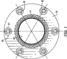
本発明は、管状の石英の覆い(sheath)のような管状部材の外面から付着物を取り除くスクレーパを与える。現在における本発明の好ましい実施例では、スクレーパは、複数のスクレーパアセンブリを具えるスクレーパカートリッジを与える。複数のスクレーパアセンブリには、互いに角度的なオフセットがあって、スクレーパカートリッジは、掃除される管状部材の外側表面に接触する。特に図1及び図2を参照すると、離間した同軸の一対の円環状の板がある。第1板(10)及び第2板(20)には、円状の開口(11)及び開口(12)が夫々設けられている。スクレーパカートリッジ(30)は、第1板(10)と第2板(20)の間に配置される。第1板(10)と第2板(20)の内側表面の間には、複数のスペーサ部材(40)が、各々の円環状の板の端にて、第1板(10)及び第2板(20)の内側表面の間に配置される。各スペーサ部材(40)は、管状部材(41)を具えており、調整可能な留め具(42)が、管状部材(41)と、個々の板(10)及び板(20)の端にある開口(43)とを通るように配置される。好ましい実施例では、留め具(42)は着脱自在なボルトであって、これによって、スクレーパの組立て又は分解が容易に行われる。代わりに、個々の板(10)及び(20)の内側表面の端に接合された金属棒材のような、常設されるスペーサ部材が、スクレーパの組立て中に固定されてもよい。
【0019】
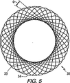
図3乃至図5を参照すると、スクレーパカートリッジ(30)は、弾性のある複数のワイヤアセンブリ(31)を具えており、各アセンブリ(31)は、弾性のある細長いワイヤ(32)である。スクレーパカートリッジ(30)は、多角形の横断面を有するのが好ましい。各ワイヤは、一体的に連結された一連の弾性セグメント(33)を規定するように曲げられている。隣接するセグメントの各対は、湾曲部(34)を介して接続されている。湾曲部(34)は、アセンブリ(31)が、比較的真っ直ぐな一連の弾性セグメント(33)と丸い湾曲部(34)とで構成されるように、曲げられている。ワイヤ(32)は、約1000分の10乃至20インチの太さを有している。
【0020】
現在において好ましい本発明の実施例の図4に示すように、スクレーパのセグメント(33)の隣接する対は、湾曲部(34)によって形成された60度の角度で、ほぼ三角形を構成するように配置されている。しかしながら、各アセンブリが、掃除される管状部材の外側表面と接する少なくとも1つのセグメントを有するならば、より多くのセグメント(33)と共にその他の角度が採用されてもよいことに留意すべきである。
【0021】
図3を参照すると、スクレーパのアセンブリ(31)は、ほぼ三角形の形状をなすようにカートリッジ(30)に配置されており、セグメント(32)は互いに、角度φで角度的に離れている。角度φは、約10度である。φが約10度であり、掃除される管状部材の外径が35ミリである場合、カートリッジ(30)を作製するのに用いられる弾性ワイヤアセンブリ(31)の数は、約32となる。
【0022】
作業では、スクレーパが、掃除される管状部材を覆うように、開口(11)を用いて同軸状に配置されると、カートリッジ(30)の接面したセグメント(32)は、軸方向に外側に押されることで、ワイヤの弾性によって弓状に変形する。セグメント(32)の弓状の部分は、掃除される管状部材の外側表面に押される。これによって、当該技術分野における通常の知識を有する者にはよく知られた方法で、管の表面に沿った前後の往復運動に伴って、管の表面を擦って掃除する作業がなされる。
【0023】
現在における本発明の好ましい実施例が詳細に図示及び説明されたが、本発明は、添付の特許請求の範囲内において別の態様で実施されてよい。
【図面の簡単な説明】
【0024】
【図1】図1は、本発明のスクレーパの現在における好ましい実施例の正面図である。
【図2】図2は、図1に示された本発明の実施例の側面図である。
【図3】図3は、個々のワイヤアセンブリを具えるスクレーパカートリッジの側面図である。
【図4】図4は、隣接するセグメント対の湾曲部で接続された3つのセグメントを有する好ましいアセンブリの正面図である。
【図5】図5は、図3のスクレーパカートリッジの正面図である。【Technical field】
[0001]
The present invention generally relates to an improved apparatus for removing scale, rust, organic deposits, and inorganic deposits from the outer surface of a tubular member. More particularly, the present invention relates to an apparatus that reduces clogging of an apparatus that cleans the outer surface of a quartz sleeve that houses an ultraviolet lamp used to sterilize fluids and generate photochemical reactions.
[Background]
[0002]
When the ultraviolet (UV) lamp was first used to treat water that could contain harmful bacteria and viruses, it was known that the outer surface of the lamp was coated with impurities in the water. For example, if the UV lamp is submerged in water, most of the UV lamp in the protective quartz sleeve will enter the water. Such types of UV lamps operate at a surface temperature of 40 ° C. to 800 ° C., depending on the type of lamp. Water contains impurities such as calcium, manganese, and iron, which are deposited on the surface of the quartz sleeve by heat generated by the lamp contained in the quartz sleeve. Such precipitation hinders ultraviolet light from sterilizing water or promoting chemical reactions from reaching the water. When the material stack becomes very prominent, all ultraviolet light is absorbed and light of wavelengths other than ultraviolet light generated by the lamp promotes the growth of microorganisms on the outer surface of the quartz sleeve. Such a coating on the quartz sleeve necessitates some in-plane cleaning systems and manual cleaning by separating and disassembling the UV unit. Cleaning the quartz tube that surrounds the UV lamp has become a major opportunity to manufacture such equipment. Various scrapers, brushes, ultrasonic cleaning, in-plane acid cleaning, air cleaning, and chemicals have been proposed to solve this problem.
[0003]
Conventional scrapers or wipers usually include a portion formed of felt, rubber, metal, plastic or Teflon and are pushed or pulled in the length direction of the quartz tube or around the quartz tube. . These conventional systems describe various ways to achieve this goal. U.S. Pat. No. 1,998,076 relating to scrapers was granted to HMCreighton et al. The scraper is pressed against the quartz sleeve and is driven by a set of gears with a central lamp. HMCreighton et al. Wiper improvements continued. In 1965, S. Ellner used an external motor with gear to push the scraper down the length of a quartz tube (US Pat. No. 3,182,193) inside a pressurized UV system. Did that. In US Pat. No. 3,336,099, J. Czulak et al. Described a wiper that is driven by the flow of water along the length of a quartz tube. GWRobertson also used a water flow to drive a floating wiper along the length of the quartz tube. It had fins that rotated as it moved along the quartz tube. In 1965, A. Young received US Pat. No. 3,462,597 for a wiper system with a plunger for manually pushing the wiper in a single-ended quartz tube length method. The wiper was made of Teflon (registered trademark). H. Boehme received a patent for nearly the same system in 1990. In 1965, DEWiltrout received U.S. Pat. No. 3,566,105 for hydraulic means to push the wiper along the length of the quartz tube. AFMcFarland et al. (1965 US Pat. No. 3,182,191), RWHippen (1971 US Pat. No. 3,562,520), DGHagger and RLPetersen (1993 US Pat. No. 5,227,140) Used a spring to return the wiper to the rest position when the water flow stopped. In US Pat. No. 4,367,140, MDWood elaborated on the wiper idea when cleaning all of the UV array using one assembly. See, for example, FIG. 3 of that patent. This system was unsuccessful due to resistance issues leading to quartz sleeve failure. US Pat. No. 5,528,044 was granted to JAHutchison in 1996 for a wiper made from a flat piece of very thin metal (FIG. 1 of that patent). There was a small cut in the inner circumference of the wiper, and the wiper bent as it moved along the quartz tube.
[0004]
RLPeterson received US Pat. No. 5,501,843 in 1996 for a wiper (FIG. 6 of that patent) using a cartridge filled with stainless steel filings or wool.
[0005]
In a pressurized UV system (RMGBoucher US Pat. No. 3,672,823, EAPedziwiatr US Pat. No. 4,728,368, JMMaarschalkerweerd US Pat. No. 5,539,209), semi-pressurized (semi -puressurized) Cleaning the quartz sleeve using ultrasound in the UV system (S.Ellner US Pat. No. 4,358,204) and in the UV probe (JMMaarschalkerweerd US Pat. No. 5,539,210) A patent was issued for this. The ultrasound system used to clean the wastewater UV system has not been effective (US Environmental Protection Agency, 1986).
[0006]
US Pat. No. 5,133,945 was awarded to Hallett et al. In 1992 for the use of a brush to clean a quartz sleeve in a pressurized UV system. In 1993, German design DE 3710250 was awarded to W. Stellrecht et al. For cleaning the quartz sleep and the inner surface of the pressurized UV unit with a brush.
[0007]
S. Ellner was awarded US Pat. No. 4,103,167, US Pat. No. 4,899,056 and Re 34,513 in 1978, 1990 and 1994, respectively. These patents relate to the use of acids in cleaning quartz sleeves placed in recirculation systems or in cleaning quartz sleeves after lifting the UV module out of the conduit. All of these methods required the UV system to be out of service. P. Binot was awarded US Pat. No. 5,725,757 in 1997 for cleaning a pressurized UV system using an acid and air injection system.
[0008]
P. Schuerch et al. Was awarded US Pat. No. 5,332,388 in 1994 for an air cleaning system for a vertical lamp UV system for disinfecting sewage.
[0009]
JMMaarschalkerweerd was awarded US Pat. No. 5,418,370 in 1995 for a chemical and mechanical method of cleaning a quartz sleeve in a semi-pressurized UV system. The quartz sleeve contacts the sleeve, the acid in the sleeve dissolves any inorganic material, and the seal at the front of the sleeve scrapes off any deposits. The cleaning system was modified so that the sleeve moved along the quartz sleeve. E. Ishiyama invented a chemical and mechanical method for cleaning a quartz sleeve in an open channel parallel flow UV system with a horizontal lamp, and in 1999, US Pat. , 740. The acid detergent needs to be replenished continuously.
[0010]
On August 13, 2002, US Pat. No. 6,432,213 B2 was awarded to Wang and Sotirakos. This patent relates to a scraper that removes deposits from the outer surface of a tubular member (see FIG. 1 of this patent). The scraper includes an element defining an outer jacket having an annular recess opened inward and two axially positioned openings, and a scraper element. The scraper element is formed of an elongated, non-circular elastic wire and is bent to define a series of integrally connected elastic segments. Each pair of adjacent segments is connected via a bent portion or a curved portion. This scraper is expensive to make because the outer jacket needs to be precisely machined. Further, while this scraper is very effective, when used in a quartz sleeve of a UV system that treats sewage, the inside of the outer jacket tends to become clogged with organic matter, sand and other materials. Examples of UV systems in which this scraper can be used are shown in US Pat. Nos. 5,006,244, 4,482,809, 4,757,205, and 6,231,820B1. Has been. If the sewage flow is parallel to the lamps in these UV systems and perpendicular to the scraper, debris will be captured by the scraper wire. Since the outer periphery of the scraper is closed, this debris does not flow out. This debris or sand is often tightly packed inside the outer jacket whose outer periphery is closed by the removal operation, and disturbs the function of the scraper.
[0011]
Accordingly, it is an object of the present invention to provide a scraper that uses the advantages of the curved segment of elastic wire of US Pat. No. 6,432,213 B2, while not having its disadvantages. A further object of the present invention is to provide an effective scraper for use in a UV quartz housing that can be manufactured at a relatively low cost.
DISCLOSURE OF THE INVENTION
[0012]
The present invention solves the clogging problem by removing the outer cylindrical wall from the scraper. This expels organic matter, debris, sand, etc. from the scraper and increases the time interval between inspections.
[0013]
The hollow cylinder is replaced with two plates. Each of these plates has a cylindrical opening. These plates can be made by stamping metal or UV resistant plastic plates without the need for machining.
[0014]
Generally, scraper of the present invention is positioned together, and the first plate spaced apart annular and comprises a second plate, the inner diameter of each of the plate is slightly larger than the outer diameter of the tube to be cleaned by the scraper . In practice, it is preferred that the openings in the annular plate are sufficiently large so that the scraper cartridge inserted between them extends into each opening when it fits into the tube during cleaning. The plates are maintained in a spaced relationship without the use of spacers or at least one spacer is mounted on the inner surface of each disc at its outer end.
[0015]
The scraper cartridge is disposed between the spaced apart annular first and second plates and includes a plurality of elongated elastic wire assemblies. Each wire assembly is defined by a series of elastic wire segments connected together. Each pair of adjacent segments is connected via a curved portion. In the presently preferred embodiment of the present invention, each assembly comprises three segments that are configured to axially deform against the surface of the tube to be cleaned. In this embodiment, the bending angle of the segment is approximately 60 degrees. However, in other embodiments of the invention, the number of segments may be varied and the angle of curvature may be increased if one segment maintains a sufficient contact relationship with the tube to be cleaned. The plurality of wire assemblies constitute a scraper cartridge, and the inner diameter of the scraper cartridge is slightly smaller than the outer diameter of the tube to be cleaned. With this arrangement, each segment of the assembly that contacts the tube to be cleaned is slightly arcuate to provide a wider contact area between the segment and the tube. Due to elasticity, the wire bends and pushes its outer surface inward toward the tube. This makes it possible to perform the work of rubbing and cleaning the surface. By configuring all the wire segments of the cartridge to push the tube surface inward, effective cleaning is achieved by back and forth movement along the axial direction of the tube to be cleaned.
[0016]
When the material is scraped off the outer surface of the tube to be cleaned, the scraper of the present invention pushes the material along the tip of the scraper cartridge. However, any material entrained in the cartridge assembly will escape radially out through the cartridge due to the movement of the scraper and the water pushed by the scraper during such cleaning operations.
[0017]
Other advantages of the present invention will become apparent upon reading the detailed description of the presently preferred embodiments of the invention in conjunction with the accompanying drawings.
BEST MODE FOR CARRYING OUT THE INVENTION
[0018]
The present invention provides a scraper that removes deposits from the outer surface of a tubular member, such as a tubular quartz sheath. In the presently preferred embodiment of the present invention, the scraper provides a scraper cartridge comprising a plurality of scraper assemblies. The plurality of scraper assemblies are angularly offset from each other so that the scraper cartridge contacts the outer surface of the tubular member to be cleaned. With particular reference to FIGS. 1 and 2, there is a pair of spaced apart coaxial annular plates. The first plate (10) and the second plate (20) are provided with circular openings (11) and openings (12), respectively. The scraper cartridge (30) is disposed between the first plate (10) and the second plate (20). Between the inner surfaces of the first plate (10) and the second plate (20), there are a plurality of spacer members (40) at the end of each annular plate, the first plate (10) and the second plate (2). Located between the inner surfaces of the plate (20). Each spacer member (40) comprises a tubular member (41) with adjustable fasteners (42) at the ends of the tubular member (41) and the individual plates (10) and plates (20). It is arranged to pass through the opening (43). In the preferred embodiment, the fastener (42) is a detachable bolt that facilitates assembly or disassembly of the scraper. Alternatively, permanent spacer members, such as metal bars joined to the inner surface edges of the individual plates (10) and (20), may be secured during assembly of the scraper.
[0019]
Referring to FIGS. 3-5, the scraper cartridge (30) comprises a plurality of elastic wire assemblies (31), each assembly (31) being an elastic elongated wire (32). The scraper cartridge (30) preferably has a polygonal cross section. Each wire is bent to define a series of elastic segments (33) connected together. Each pair of adjacent segments is connected via a curved portion (34). The bend (34) is bent so that the assembly (31) is composed of a series of relatively straight elastic segments (33) and a round bend (34). The
[0020]
As shown in FIG. 4 of the presently preferred embodiment of the present invention, adjacent pairs of scraper segments (33) form approximately a triangle at an angle of 60 degrees formed by the curved portion (34). Has been placed. However, it should be noted that other angles may be employed with more segments (33) if each assembly has at least one segment in contact with the outer surface of the tubular member to be cleaned.
[0021]
Referring to FIG. 3, the scraper assembly (31) is disposed in the cartridge (30) so as to form a substantially triangular shape, and the segments (32) are angularly separated from each other by an angle φ. The angle φ is about 10 degrees. If φ is about 10 degrees and the outer diameter of the tubular member to be cleaned is 35 mm, the number of elastic wire assemblies (31) used to make the cartridge (30) will be about 32.
[0022]
In operation, when the scraper is placed coaxially with the opening (11) so as to cover the tubular member to be cleaned, the abutting segment (32) of the cartridge (30) is axially outward. By being pushed, it is deformed into a bow shape by the elasticity of the wire. The arcuate portion of segment (32) is pushed against the outer surface of the tubular member to be cleaned. This allows the tube surface to be rubbed and cleaned in a manner well known to those having ordinary knowledge in the art as the tube reciprocates back and forth along the tube surface.
[0023]
While presently preferred embodiments of the invention have been shown and described in detail, the invention may be practiced otherwise than within the scope of the appended claims.
[Brief description of the drawings]
[0024]
FIG. 1 is a front view of a presently preferred embodiment of a scraper of the present invention.
FIG. 2 is a side view of the embodiment of the present invention shown in FIG.
FIG. 3 is a side view of a scraper cartridge comprising individual wire assemblies.
FIG. 4 is a front view of a preferred assembly having three segments connected by the bends of adjacent segment pairs.
FIG. 5 is a front view of the scraper cartridge of FIG. 3;
Claims (6)
a.互いに位置決めされており、離間した第1及び第2の円環状の板と、
b.第1及び第2の円環状の板の各々の内側表面の外端に配置された複数のスペーサと、
c.第1及び第2の円環状の板の間に位置決めされて装着されたスクレーパカートリッジとを具えており、
スクレーパカートリッジは、複数の弾性ワイヤアセンブリを具えており、それら弾性ワイヤアセンブリは、管状部材の外径よりも小さい径を有する開口を規定するように配置されており、
複数の弾性ワイヤアセンブリの各々は、少なくとも3つの一体的に連結された一連の弾性セグメントを有する弾性ワイヤで構成されており、
それら弾性セグメントは、隣接する弾性セグメントの間にある湾曲部によって規定されており、
少なくとも1つの弾性セグメントは、開口を通って配置される管状部材の外側表面と変形して接触するように、カートリッジ内に位置決めされている、スクレーパ。A scraper for removing deposits from the outside of the tubular member,
a. First and second annular plates positioned relative to each other and spaced apart;
b. A plurality of spacers disposed at the outer ends of the inner surfaces of each of the first and second annular plates;
c. A scraper cartridge positioned and mounted between the first and second annular plates;
The scraper cartridge comprises a plurality of elastic wire assemblies, the elastic wire assemblies being arranged to define an opening having a diameter smaller than the outer diameter of the tubular member;
Each of the plurality of elastic wire assemblies is comprised of an elastic wire having a series of at least three integrally connected elastic segments;
The elastic segments are defined by a bend between adjacent elastic segments,
A scraper, wherein the at least one elastic segment is positioned within the cartridge such that it deforms and contacts the outer surface of a tubular member disposed through the opening.
Applications Claiming Priority (3)
| Application Number | Priority Date | Filing Date | Title |
|---|---|---|---|
| US11/008,827 US7159264B2 (en) | 2004-12-10 | 2004-12-10 | Scraper for cleaning tubular members |
| US11/008,827 | 2004-12-10 | ||
| PCT/US2005/042937 WO2006065508A2 (en) | 2004-12-10 | 2005-11-29 | Scraper for cleaning tubular members |
Publications (3)
| Publication Number | Publication Date |
|---|---|
| JP2008522810A JP2008522810A (en) | 2008-07-03 |
| JP2008522810A5 JP2008522810A5 (en) | 2011-03-24 |
| JP4937133B2 true JP4937133B2 (en) | 2012-05-23 |
Family
ID=36582101
Family Applications (1)
| Application Number | Title | Priority Date | Filing Date |
|---|---|---|---|
| JP2007545511A Expired - Fee Related JP4937133B2 (en) | 2004-12-10 | 2005-11-29 | Tubular member cleaning scraper |
Country Status (11)
| Country | Link |
|---|---|
| US (1) | US7159264B2 (en) |
| EP (2) | EP1833620B1 (en) |
| JP (1) | JP4937133B2 (en) |
| KR (1) | KR101270325B1 (en) |
| AU (1) | AU2005316905B2 (en) |
| CA (1) | CA2587442C (en) |
| ES (2) | ES2388870T3 (en) |
| NZ (1) | NZ555030A (en) |
| PL (2) | PL1833620T3 (en) |
| TW (1) | TW200635674A (en) |
| WO (1) | WO2006065508A2 (en) |
Families Citing this family (14)
| Publication number | Priority date | Publication date | Assignee | Title |
|---|---|---|---|---|
| US8459861B2 (en) * | 2008-11-26 | 2013-06-11 | Calgon Carbon Corporation | Method and apparatus for use of mixing elements in wastewater / recycle water UV disinfection system |
| WO2015044074A1 (en) * | 2013-09-26 | 2015-04-02 | Cgg Services Sa | Device and methods for low contact cable cleaning |
| CN104741345B (en) * | 2013-12-31 | 2017-05-17 | 上海长园电子材料有限公司 | Surface oil remover |
| CN105537209B (en) * | 2014-10-31 | 2018-02-02 | 中国石油天然气股份有限公司 | Pipeline cleaning device |
| SE1650595A1 (en) | 2016-05-03 | 2017-10-24 | Wallenius Water Ab | A UV light liquid treatment system |
| SE541117C2 (en) * | 2017-02-17 | 2019-04-09 | Wallenius Water Innovation Ab | A liquid treatment system comprising at least one ultra-violet (UV) treatment lamp |
| SE540414C2 (en) | 2017-02-17 | 2018-09-11 | Wallenius Water Innovation Ab | A liquid treatment system including a cleaning arrangement |
| WO2019213188A1 (en) * | 2018-05-04 | 2019-11-07 | James Van Voorhis | Pipeline washing and drying system |
| CN110293092A (en) * | 2019-07-02 | 2019-10-01 | 罗瑞芳 | A kind of high-end equipment manufacturing grinding device |
| SE544296C2 (en) | 2020-02-06 | 2022-03-29 | Wallenius Water Innovation Ab | Cleaning arrangement for a liquid treatment system |
| CN111420944B (en) * | 2020-04-10 | 2021-04-13 | 浙江科技学院 | Rotary scraper machine |
| CN112718661B (en) * | 2020-12-22 | 2021-11-02 | 徐州瑞马智能技术有限公司 | Galvanizing equipment for treating outer surface of steel and using method |
| CN114396500A (en) * | 2021-12-28 | 2022-04-26 | 武汉思能物联网科技有限公司 | Multifunctional hydraulic control valve with low pressure loss |
| DK181491B1 (en) * | 2022-04-11 | 2024-03-07 | Rigtools Aps | System for pipe cleaning |
Citations (1)
| Publication number | Priority date | Publication date | Assignee | Title |
|---|---|---|---|---|
| JP2003531004A (en) * | 2000-04-20 | 2003-10-21 | 株式会社日本フォトサイエンス | Scraper for tubular members |
Family Cites Families (34)
| Publication number | Priority date | Publication date | Assignee | Title |
|---|---|---|---|---|
| US1253363A (en) * | 1917-03-01 | 1918-01-15 | Charles A Farr | Printing-roller-cleaning device. |
| US1998076A (en) | 1931-10-08 | 1935-04-16 | R U V Engineering Corp | Active ray treating device |
| US3182193A (en) | 1962-01-03 | 1965-05-04 | Ultra Dynamics Corp | Electronically monitored liquid purification or sterilizing system |
| US3336099A (en) | 1963-01-23 | 1967-08-15 | Czulak Joseph | Apparatus for the sanitization of liquids with especial application to water storages and swimming pools |
| US3182191A (en) | 1963-02-14 | 1965-05-04 | Puretest Water Purifier Co | Water purifying apparatus with an automatically actuated wiper for the ultra-violet source |
| US3462597A (en) | 1966-07-29 | 1969-08-19 | Ultra Dynamics Corp | Ultraviolet fluid purifier having manually operable wiper means |
| US3566105A (en) | 1968-08-16 | 1971-02-23 | Ultra Dynamics Corp | System for ultraviolet irradiation of fluids with fail safe monitoring means |
| US3562520A (en) | 1968-11-04 | 1971-02-09 | Puretest Water Purifying Co | Fail-safe water purifying apparatus |
| US3672823A (en) | 1970-03-25 | 1972-06-27 | Wave Energy Systems | Method of sterilizing liquids |
| DE2549321A1 (en) * | 1975-11-04 | 1977-05-12 | Gottfried Baumann | Strip metal coil with angled bends - having polygonal profile formed from strip continually bent at regular angle |
| US4103167A (en) | 1976-08-16 | 1978-07-25 | Sidney Ellner | Ultraviolet liquid purification system |
| US4367410A (en) | 1979-07-09 | 1983-01-04 | Pure Water Systems, Inc. | Waste purification apparatus and method |
| US4358204A (en) | 1980-09-22 | 1982-11-09 | Sidney Ellner | Ultrasonic cleaning apparatus |
| CA1163086A (en) | 1981-11-30 | 1984-03-06 | Jan Maarschalkerweerd | Ultraviolet fluid purifying device |
| US4728368A (en) | 1986-04-25 | 1988-03-01 | Pedziwiatr Edward A | Ultrasonic cleaning in liquid purification systems |
| US4757205A (en) | 1986-06-10 | 1988-07-12 | Arlat Inc. | Ultraviolet water treatment apparatus |
| DE3710250C3 (en) | 1987-03-28 | 1993-11-18 | Ultralight Ag Schaanwald | Device for disinfecting water by UV radiation |
| JP2660847B2 (en) * | 1988-05-07 | 1997-10-08 | 株式会社東京機械製作所 | Equipment for removing accumulated dirt |
| US4899056A (en) | 1988-07-07 | 1990-02-06 | Ultraviolet Purification Systems, Inc. | Cleaning system for ultraviolet light producing lamps |
| US5006244A (en) | 1988-09-13 | 1991-04-09 | Trojan Technologies, Inc. | Fluid purification device |
| US4922114A (en) | 1989-06-01 | 1990-05-01 | Hilary Boehme | Wiper mechanism |
| US5227140A (en) | 1990-04-13 | 1993-07-13 | Peroxidation Systems, Inc. | Modular self-cleaning oxidation chamber |
| US5133945A (en) | 1991-06-17 | 1992-07-28 | Solarchem Enterprises Inc. | UV lamp transmittance controller |
| US5332388A (en) | 1992-12-04 | 1994-07-26 | Infilco Degremont, Inc. | Ultraviolet disinfection module |
| TW360619B (en) | 1993-03-05 | 1999-06-11 | Trojan Techn Inc | A cleaning apparatus for a radiation source assembly in a fluid treatment system and a method of removal of fouling materials therefrom |
| CH686116A5 (en) * | 1994-08-18 | 1996-01-15 | Franz Disler | Solvent evaporation unit for solutions and suspensions |
| US5501843A (en) | 1994-10-14 | 1996-03-26 | Vulcan Peroxidation Systems, Inc. | Wiper cartridge |
| US5539209A (en) | 1994-10-17 | 1996-07-23 | Trojan Technologies Inc. | Method of cleaning fouling materials from a radiation module |
| FR2729382B1 (en) | 1995-01-16 | 1997-03-28 | Omnium Traitement Valorisa | UV IRRADIATION REACTOR FOR THE TREATMENT OF LIQUIDS |
| US5528044A (en) | 1995-04-28 | 1996-06-18 | Solar Kinetics, Inc. | Wiper assembly for ultraviolet-light reactor tubes |
| US5874740A (en) | 1996-03-14 | 1999-02-23 | Photoscience Japan Corporation | Ultraviolet ray irradiation equipment having scraper rings fitted to light transmission tubes |
| DE19653083B4 (en) | 1996-12-19 | 2005-09-08 | Wedeco Ag Water Technology | Streamlined UV disinfection device |
| WO2003024873A1 (en) | 2001-09-18 | 2003-03-27 | Photoscience Japan Corporation | Ultraviolet water treatment apparatus with dome-shaped baffle |
| CN2656033Y (en) | 2003-09-19 | 2004-11-17 | 福建新大陆环保科技有限公司 | Ultraviolet sterilizing device with automatic cleaning apparatus |
-
2004
- 2004-12-10 US US11/008,827 patent/US7159264B2/en not_active Expired - Fee Related
-
2005
- 2005-11-29 NZ NZ555030A patent/NZ555030A/en not_active IP Right Cessation
- 2005-11-29 CA CA2587442A patent/CA2587442C/en not_active Expired - Fee Related
- 2005-11-29 PL PL05825584T patent/PL1833620T3/en unknown
- 2005-11-29 KR KR1020077013506A patent/KR101270325B1/en not_active IP Right Cessation
- 2005-11-29 JP JP2007545511A patent/JP4937133B2/en not_active Expired - Fee Related
- 2005-11-29 ES ES05825584T patent/ES2388870T3/en active Active
- 2005-11-29 ES ES11163160.2T patent/ES2536587T3/en active Active
- 2005-11-29 AU AU2005316905A patent/AU2005316905B2/en not_active Ceased
- 2005-11-29 WO PCT/US2005/042937 patent/WO2006065508A2/en active Application Filing
- 2005-11-29 EP EP05825584A patent/EP1833620B1/en not_active Not-in-force
- 2005-11-29 EP EP11163160.2A patent/EP2340896B1/en not_active Not-in-force
- 2005-11-29 PL PL11163160T patent/PL2340896T3/en unknown
- 2005-12-01 TW TW094142341A patent/TW200635674A/en unknown
Patent Citations (1)
| Publication number | Priority date | Publication date | Assignee | Title |
|---|---|---|---|---|
| JP2003531004A (en) * | 2000-04-20 | 2003-10-21 | 株式会社日本フォトサイエンス | Scraper for tubular members |
Also Published As
| Publication number | Publication date |
|---|---|
| JP2008522810A (en) | 2008-07-03 |
| PL1833620T3 (en) | 2012-11-30 |
| CA2587442A1 (en) | 2006-06-22 |
| AU2005316905B2 (en) | 2011-06-16 |
| ES2388870T3 (en) | 2012-10-19 |
| AU2005316905A1 (en) | 2006-06-22 |
| US7159264B2 (en) | 2007-01-09 |
| WO2006065508A2 (en) | 2006-06-22 |
| EP2340896A1 (en) | 2011-07-06 |
| NZ555030A (en) | 2009-09-25 |
| KR101270325B1 (en) | 2013-05-31 |
| KR20070086232A (en) | 2007-08-27 |
| WO2006065508A3 (en) | 2007-03-29 |
| EP1833620A2 (en) | 2007-09-19 |
| PL2340896T3 (en) | 2015-08-31 |
| EP1833620B1 (en) | 2012-06-06 |
| ES2536587T3 (en) | 2015-05-26 |
| CA2587442C (en) | 2013-05-21 |
| EP2340896B1 (en) | 2015-03-11 |
| US20060123571A1 (en) | 2006-06-15 |
| TW200635674A (en) | 2006-10-16 |
Similar Documents
| Publication | Publication Date | Title |
|---|---|---|
| JP4937133B2 (en) | Tubular member cleaning scraper | |
| JP4624634B2 (en) | Scraper for tubular members | |
| US10968116B2 (en) | Liquid treatment system | |
| US11001510B2 (en) | Liquid treatment system | |
| US20230025794A1 (en) | Cleaning arrangement for a liquid treatment system | |
| KR200331333Y1 (en) | UV Sterilizer with Rubbing and Pushing Wiper System |
Legal Events
| Date | Code | Title | Description |
|---|---|---|---|
| A621 | Written request for application examination |
Free format text: JAPANESE INTERMEDIATE CODE: A621 Effective date: 20081016 |
|
| A977 | Report on retrieval |
Free format text: JAPANESE INTERMEDIATE CODE: A971007 Effective date: 20100929 |
|
| A131 | Notification of reasons for refusal |
Free format text: JAPANESE INTERMEDIATE CODE: A131 Effective date: 20101109 |
|
| A524 | Written submission of copy of amendment under article 19 pct |
Free format text: JAPANESE INTERMEDIATE CODE: A524 Effective date: 20110203 |
|
| A131 | Notification of reasons for refusal |
Free format text: JAPANESE INTERMEDIATE CODE: A131 Effective date: 20110809 |
|
| A521 | Request for written amendment filed |
Free format text: JAPANESE INTERMEDIATE CODE: A523 Effective date: 20111017 |
|
| TRDD | Decision of grant or rejection written | ||
| A01 | Written decision to grant a patent or to grant a registration (utility model) |
Free format text: JAPANESE INTERMEDIATE CODE: A01 Effective date: 20120207 |
|
| A01 | Written decision to grant a patent or to grant a registration (utility model) |
Free format text: JAPANESE INTERMEDIATE CODE: A01 |
|
| A61 | First payment of annual fees (during grant procedure) |
Free format text: JAPANESE INTERMEDIATE CODE: A61 Effective date: 20120221 |
|
| FPAY | Renewal fee payment (event date is renewal date of database) |
Free format text: PAYMENT UNTIL: 20150302 Year of fee payment: 3 |
|
| R150 | Certificate of patent or registration of utility model |
Free format text: JAPANESE INTERMEDIATE CODE: R150 |
|
| A524 | Written submission of copy of amendment under article 19 pct |
Free format text: JAPANESE INTERMEDIATE CODE: A524 Effective date: 20110203 |
|
| R250 | Receipt of annual fees |
Free format text: JAPANESE INTERMEDIATE CODE: R250 |
|
| R250 | Receipt of annual fees |
Free format text: JAPANESE INTERMEDIATE CODE: R250 |
|
| R250 | Receipt of annual fees |
Free format text: JAPANESE INTERMEDIATE CODE: R250 |
|
| LAPS | Cancellation because of no payment of annual fees |