JP4624634B2 - Scraper for tubular members - Google Patents
Scraper for tubular members Download PDFInfo
- Publication number
- JP4624634B2 JP4624634B2 JP2001578104A JP2001578104A JP4624634B2 JP 4624634 B2 JP4624634 B2 JP 4624634B2 JP 2001578104 A JP2001578104 A JP 2001578104A JP 2001578104 A JP2001578104 A JP 2001578104A JP 4624634 B2 JP4624634 B2 JP 4624634B2
- Authority
- JP
- Japan
- Prior art keywords
- scraper
- tubular member
- wire
- aligned
- elasticity
- Prior art date
- Legal status (The legal status is an assumption and is not a legal conclusion. Google has not performed a legal analysis and makes no representation as to the accuracy of the status listed.)
- Expired - Fee Related
Links
- 239000012634 fragment Substances 0.000 claims description 13
- 238000004140 cleaning Methods 0.000 claims description 12
- 238000000034 method Methods 0.000 claims description 6
- 230000002093 peripheral effect Effects 0.000 claims 3
- XLYOFNOQVPJJNP-UHFFFAOYSA-N water Substances O XLYOFNOQVPJJNP-UHFFFAOYSA-N 0.000 description 15
- 230000001681 protective effect Effects 0.000 description 11
- 239000000463 material Substances 0.000 description 8
- 239000012530 fluid Substances 0.000 description 7
- 239000010453 quartz Substances 0.000 description 7
- VYPSYNLAJGMNEJ-UHFFFAOYSA-N silicon dioxide Inorganic materials O=[Si]=O VYPSYNLAJGMNEJ-UHFFFAOYSA-N 0.000 description 7
- 238000007790 scraping Methods 0.000 description 6
- 230000005855 radiation Effects 0.000 description 5
- 238000004659 sterilization and disinfection Methods 0.000 description 4
- 239000004809 Teflon Substances 0.000 description 3
- 229920006362 Teflon® Polymers 0.000 description 3
- 238000005452 bending Methods 0.000 description 3
- 238000006243 chemical reaction Methods 0.000 description 3
- 239000004033 plastic Substances 0.000 description 3
- 238000011282 treatment Methods 0.000 description 3
- 229920002313 fluoropolymer Polymers 0.000 description 2
- 239000004811 fluoropolymer Substances 0.000 description 2
- 230000001954 sterilising effect Effects 0.000 description 2
- 241000894006 Bacteria Species 0.000 description 1
- 239000012620 biological material Substances 0.000 description 1
- 230000005540 biological transmission Effects 0.000 description 1
- 230000001680 brushing effect Effects 0.000 description 1
- 239000002131 composite material Substances 0.000 description 1
- 238000010586 diagram Methods 0.000 description 1
- 230000005484 gravity Effects 0.000 description 1
- 210000004209 hair Anatomy 0.000 description 1
- 239000007788 liquid Substances 0.000 description 1
- 239000012528 membrane Substances 0.000 description 1
- 239000002184 metal Substances 0.000 description 1
- 238000012986 modification Methods 0.000 description 1
- 230000004048 modification Effects 0.000 description 1
- 238000000746 purification Methods 0.000 description 1
- 239000013049 sediment Substances 0.000 description 1
- 239000000126 substance Substances 0.000 description 1
- 230000003442 weekly effect Effects 0.000 description 1
Images


Classifications
-
- B—PERFORMING OPERATIONS; TRANSPORTING
- B08—CLEANING
- B08B—CLEANING IN GENERAL; PREVENTION OF FOULING IN GENERAL
- B08B9/00—Cleaning hollow articles by methods or apparatus specially adapted thereto
- B08B9/02—Cleaning pipes or tubes or systems of pipes or tubes
- B08B9/023—Cleaning the external surface
-
- B08B1/30—
-
- B—PERFORMING OPERATIONS; TRANSPORTING
- B21—MECHANICAL METAL-WORKING WITHOUT ESSENTIALLY REMOVING MATERIAL; PUNCHING METAL
- B21C—MANUFACTURE OF METAL SHEETS, WIRE, RODS, TUBES OR PROFILES, OTHERWISE THAN BY ROLLING; AUXILIARY OPERATIONS USED IN CONNECTION WITH METAL-WORKING WITHOUT ESSENTIALLY REMOVING MATERIAL
- B21C43/00—Devices for cleaning metal products combined with or specially adapted for use with machines or apparatus provided for in this subclass
-
- C—CHEMISTRY; METALLURGY
- C02—TREATMENT OF WATER, WASTE WATER, SEWAGE, OR SLUDGE
- C02F—TREATMENT OF WATER, WASTE WATER, SEWAGE, OR SLUDGE
- C02F1/00—Treatment of water, waste water, or sewage
- C02F1/30—Treatment of water, waste water, or sewage by irradiation
- C02F1/32—Treatment of water, waste water, or sewage by irradiation with ultraviolet light
- C02F1/325—Irradiation devices or lamp constructions
-
- C—CHEMISTRY; METALLURGY
- C02—TREATMENT OF WATER, WASTE WATER, SEWAGE, OR SLUDGE
- C02F—TREATMENT OF WATER, WASTE WATER, SEWAGE, OR SLUDGE
- C02F2201/00—Apparatus for treatment of water, waste water or sewage
- C02F2201/32—Details relating to UV-irradiation devices
- C02F2201/324—Lamp cleaning installations, e.g. brushes
Description
【0001】
発明の分野
本発明は、管状部材の外面にスケール、堆積物などが残らないようにする方法および装置に関する。本発明は、水および他の液体の紫外線殺菌および/または消毒時に用いられる保護用石英製管状部材の掻き取りおよび清掃に特に適しているが、それに限られない。
【0002】
発明の背景
紫外線を水の殺菌および/または消毒に使用することがよく知られている。さらに、紫外線は、水および空気を含む流体に他の処理を行い、また反応を生じさせるのに用いることができる。紫外線は、通常、紫外線を透過させる材料からなる直線状の中空の管状部材、特に石英製管状部材の形態のランプから得られる。電気接続部が管状部材の、密閉された端部を通って延びており、これらの電気接続部は流体と接触しないように保護されている。
【0003】
紫外線ランプの表面、または外側シースが使用される場合には外側シースには、特に連続的な使用期間の後に、スケール、堆積物などが溜まりやすい。スケールおよび他の堆積物の問題は、水を処理する際に部分的に深刻になる。管状部材の表面にスケールおよび他の堆積物が堆積すると、流体に伝達される、ランプからの紫外線が減少する。このため、光の強度が低下し、その結果、処理の効率および有効性が低下する。水を処理する際には、管状部材の外面を、処理中の水の品質に応じて毎週、または毎日、場合によってはそれよりも頻繁に清掃することが要求される場合がある。
【0004】
管状部材の清掃は、管状部材を流体から切り離し、掻き取りまたは化学処理をすることによって行うことができる。このようにするために、複数の管状部材を密集させて使用する通常の状況では、装置を部分的に分解する必要があり、装置の使用の休止時間を延長する必要がある。
【0005】
管状部材を流体から切り離すことなく、ブラシ、ワイパーなどを用いて管状部材を清掃する様々な方法が開発されている。このようなシステムの1つが、1993年11月30日にHallettに発行された米国特許第5266280号明細書に開示されている。このシステムでは、円筒状のUV透過シースが、UVランプを反応容器の内部空間から隔離するのに用いられている。このシースは、UVランプを流体から隔離するように密閉されている。ブラシ装置が、シースの外面をブラッシングして、流体から堆積した物質を除去するために設けられている。このブラシ装置は、ブラシによってシースの周りを囲んだ時に半径方向内側にシースの方へ延びる荒い毛を有する少なくとも2つのブラシを有している。これらのブラシは、ブラシを、好ましくは周期的にシースの外側に沿って往復運動させる装置と共にシース上で間隔をおいて互いに連結されている。
【0006】
1969年8月19日にYoungに発行された米国特許第3462597号明細書には、UVランプを囲む保護用シース用のワイパーシステムを含む、水を浄化するUVランプシステムが開示されている。このワイパーシステムは、UV放射の影響を受けないテフロン(商標)または同様の材料から形成されたワイパーリングを有している。各リングは、互いに間隔をおいて配置されており、ばねによって保護用管状部材の外面に弾性的に、すなわち弾力を伴って保持できるように裂け目を入れられているのが好ましい。ワイパーリングは、反応器の端部を通って延びるロッドに係合したリングホルダに連結されている。そして、リングホルダは、管状部材の外側に堆積した、物理的または生物的な物質を除去するために保護用管状部材に沿って拭き取り動作をするように往復運動させられる。しかし、このシステムは、通常石英から形成される保護用管状部材の寸法の変動への対処が不十分であると考えられる。さらに、テフロン(商標)フッ化樹脂または同様の材料で作られたワイパーリングを使用すると、a)(かみそりのような)鋭く堅い掻き取り面がなく、b)テフロンフッ化樹脂に特有の滑りやすさのために、石英の表面はきれいにならない。
【0007】
1971年2月にHippenに発行された米国特許第3562520号明細書には、UVランプを囲む保護用石英製管状部材を日常的に清掃するのにワイパーシステムを用いることが開示されている。ワイパーシステムは、保護用管状部材の外面を囲み、この外面に拭き取りを行うように接触する複数のリング状のワイパー部材を含んでいる。ワイパー組立体は、コイルばねによって管状部材に沿って付勢されている。処理すべき水が反応器を通って流れると、ワイパーは管状部材の他方の端部に向かって戻され、管状部材の、入口と出口の間の領域の拭き取りが行われる。これによって、水浄化装置が始動される度に保護用管状部材から堆積物を除去することができると記載されている。
【0008】
1975年9月9日にFreeに発行された米国特許第3904363号明細書には、同様に水の流れによって作動させられるワイパーシステムが開示されている。しかし、水の流れが継続される間、保護用管状部材は清掃されない。ワイパーシステムは、水の流れによって管状部材の一方の端部に移動させられ、そこに保持される。水が遮断されると、ワイパーは重力の影響の下で反応器の底へと下降する。このワイパーシステムは可撓性の半剛性のプラスチックまたは可撓性の金属の膜を含んでいる。この膜は、複合材料またはプラスチック材料からなる、ブラシ状に形成された膜であってよい。しかし、この膜は非常に薄く、保護用シース上の頑固な堆積物を除去するのには不適切であることが多い。さらに、プラスチック製のワイパーは、高出力のランプからの、強度の強いUV放射を受けると劣化する。
【0009】
米国特許第3562520号明細書および第3904363号明細書に開示された装置が、水が連続的に流れている状態で動作できないことは、装置内を通って水が流れ続けると、堆積物が保護用管状部材上に徐々に溜まっていくことを意味する。このために、UV光の伝達が減り、その結果、細菌の処理時のUV放射の効果が低下する。
【0010】
1996年6月18日にHutchinsonに発行された米国特許第5528044号明細書には、反応容器の外部からワイパー組立体を機械的に往復運動させるように動かすことができるロッドを有するワイパー組立体を用いることが開示されている。このワイパー組立体は、ランプを囲む管状部材の外面に係合する、半径方向内側に延びる複数の指状部材を有するプレートを有している。
【0011】
他の特許には、全てMaarschalkerweerdに発行された米国特許第4482809号、米国特許第4872980号、米国特許第5006244号、および米国特許第5418370号がある。これらの特許のうちの最初の3つに記載された装置では、UVランプを囲むスリーブは周期的に異物で汚染され、そこで、このような物質を除去する、手作業による清掃が必要になる。最後の特許では、放射線源の組立体の外側の一部に係合し、引ッ込んだ位置と差し出された位置の間で移動することができる清掃スリーブを組み込んだ清掃装置を設けることによってこの欠点を解消している。この清掃スリーブは、放射線源の一部に接触するチャンバを含んでおり、このチャンバに、望ましくない材料を除去するのに適した洗浄溶液が供給されている。このような清掃方法および装置は、比較的複雑で高価なものになる傾向がある。
【0012】
管状部材の外面を清掃する簡素で効果的な方法および装置が有利である。
【0013】
発明の概要
上述の従来技術の欠点を考慮して、本発明の1つの目的は、保護用石英製シースのような管状部材の外面から堆積物を除去するスクレーパを提供することにある。
【0014】
したがって、本発明の一態様は、管状部材の外側から堆積物を除去するスクレーパであって、
内側に向かって開いた、周面に位置する凹部および互いに揃えられた軸方向の2つの開口部を形成する外側のジャケットと、
一体で、つながれた、弾性を有する一連の断片であって、互いに隣接する断片の各対が膝状湾曲部によって連結された断片を形成するように湾曲した、弾性を有する細長いワイヤの形態のスクレーパ部材とを有し、
膝状湾曲部は、少なくとも1つの断片が、互いに揃えられた軸方向の開口部の弦に実質的に沿って延びている状態で凹部内に入れられ、
管状部材を互いに揃えられた軸方向の開口部に通すには、管状部材によって少なくとも1つの断片を外側に変形させる必要があり、その結果、断片は、変形させられた断片の弾性によって内側に管状部材に対して押し付けられ、それによって、管状部材は、スクレーパが管状部材に対して軸方向に移動した際に清掃されるスクレーパを提供する。
【0015】
本発明の他の態様は、管状部材の外面から堆積物を除去する方法であって、
内側に向かって開いた、周面に位置する凹部および互いに揃えられた軸方向の2つの開口部を形成する外側ジャケットと、一体で、つながれた、弾性を有する一連の断片であって、互いに隣接する断片の各対が膝状湾曲部によって連結された断片を形成するように湾曲した、弾性を有する細長いワイヤの形態のスクレーパ部材とを含み、湾曲部は、少なくとも1つの断片が、互いに揃えられた軸方向の開口部の弦に実質的に沿って延びている状態で凹部内に入れられているスクレーパを形成することと、
少なくとも1つの断片を外側に変形させるように、管状部材を互いに揃えられた開口部に挿入し、これによって、断片は、変形させられた断片の弾性によって内側に管状部材に対して押し付けられ、それによって、管状部材を、スクレーパが管状部材に対して軸方向に移動する際に清掃することとを含む方法を提供する。
【0016】
発明の詳細な説明
本発明の2つの実施形態が添付の図に示されており、いくつかの図に亘って同様の参照番号は、同様の部分を示している。
【0017】
本発明は、管状の石英製シースのような管状部材の外面から堆積物を除去するスクレーパを提供する。本実施形態において、このスクレーパは、管状部材に接触するスクレーパ部材を備えている。このようなスクレーパ部材は、断片が、互いに揃えられた軸方向の開口部の弦に沿って延びるように外側のジャケット内に保持された、弾性を有する細長いワイヤの形態のものであってよい。このようにした場合、管状部材は、ワイヤのこの断片を外側に変形させることによってのみ、開口部に通すことができる。各断片は各断片の弾性によって管状部材に対して押し付けられ、管状部材の表面が、スクレーパを長手方向に移動させることによって清掃される。
【0018】
まず、図1を参照すると、本実施形態で説明するスクレーパ9の基本的な4つの部材が示されている。4つの部材は軸方向に揃えられているが、分かりやすくするために、分解して示されている。
【0019】
図1の1番左側に示されているのが外側のジャケット10であり、その右側にあるのがスクレーパ部材12、続いて、ワッシャー14およびサークリップ16である。図1には、1つのワッシャー14および1つのサークリップ16しか示されていないが、完全な組立体には2つのワッシャーおよび2つのサークリップが必要であることが分かる。
【0020】
図2において最もよくわかるように、外側のジャケット10は、外側の円筒状の壁18および内側の円筒状の壁20を有する中空の円筒の形状を有している。内側の円筒状の壁20には、各々がサークリップ16を入れるようになっている、間隔をおいて配置された2つの溝22が設けられている。各サークリップ16は、それに対応する溝22内の所定の位置に弾性的に「パチンと留まる(snap)」大きさになっている。図1において最も良くわかるように、各サークリップ16は、各自由端部24が、実際の直径が小さくなって、サークリップを所定の位置にパチンと留めることができるように弾性的に互いに近づくことができるような形になった、準環状の部材である。
【0021】
サークリップ16は、各々がサークリップ16の1つのすぐ隣りに位置する(ジャケット10内に破線で示されている)2つのワッシャー14を収容できるように、かつワッシャー14の間に位置するスクレーパ部材12も収容できるように互いに軸方向に間隔をおいて配置されている。
【0022】
図2では、各サークリップ16は2つの位置、すなわちジャケット10の外側と内側の両方に示しており、同様に、各ワッシャー14はジャケット10の外側と内側の両方に示していることを、混乱を避けるために述べておく。全てのこのような部材の内側の位置は破線で示されている。
【0023】
図1に戻ると、スクレーパ部材12は、一体で、つながれた、弾性を有する一連の断片26であって、互いに隣接する断片26の各対が膝状湾曲部28によって連結された断片26を形成するように湾曲した、弾性を有する細長いワイヤの形態になっている。膝状湾曲部28は丸くなっている。スクレーパ部材は、このように湾曲した時に、丸い部分によって順に連結された一連の比較的直線的な部分から成っている。より正確に言えば、好ましい実施形態のスクレーパ部材12は、弾性を有するワイヤを、各膝状湾曲部が、この膝状湾曲部からいずれかの方向に断片3つ分離れた膝状湾曲部の位置の近くに隣接しているが、これらの位置と一致していない位置に位置するように、丸い頂点を有する一連の近似的な三角形を形成するように湾曲させることによって形成されている。
【0024】
スクレーパ部材12は、ジャケット10と2つのワッシャー14によって形成された、図2に参照番号30によって示されている凹部内に入れられている。
【0025】
図5において最も良くわかるように、弾性を有する細長いワイヤを、図1に示されている形状に湾曲させた結果、ワイヤの、実質的に全ての断片が、ワッシャー14によって形成された互いに揃えられた軸方向の開口部32の弦に実質的に沿って延びている。
【0026】
どのようになっているかを理論的に示すために、開口部32の弦に沿って延びる、ワイヤの単一の断片26aのみが示されている図3を参照する。図3と図4を比較すると、管状部材(横断面が図4に34で示されている)が開口部32内の中央の位置を占める時、この管状部材は、断片26aを外側に押さなければ、そのようにできないことが分かる。しかし、ワイヤは、弾性を有しているため、図3の位置に残ろうとし、外側に変位することによって内側に管状部材34の外面に対して押し付けられ、これによって、スクレーパ9を管状部材34に沿って移動させた時に、管状部材の外面に対して掻き取る動作と清掃する動作を行うことができる。実質的に全てのワイヤ断片が内側に管状部材に対して同様に押し付けられるように構成することによって、非常に効果的で効率的な、多重の掻き取り動作が行われる。
【0027】
既に指摘したように、図5はスクレーパの構成をより正確に示す図である。
【0028】
図1に示されているワイヤの断片の数が、約100である実際の数よりもずっと少ないことをさらに指摘しておく必要がある。
【0029】
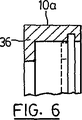
図6に示されている実施形態では、ジャケット10aの左側が、(図2の)左側のワッシャー14と同じ働きをする、内側に突き出た簡素なフランジ36に変更されている。
【0030】
このようにして、(サークリップ16によって所定の位置に保持されている)2つまたは1つのワッシャーを有するジャケット10,10aは、内側に向かって開いた、周面に位置する凹部30と、互いに揃えられた軸方向の2つの開口部32を形成していることが分かる。
【0031】
スクレーパ部材12の掻き取り機能を高めるために、弾性を有するワイヤの横断面を丸くない形状にしてもよい。弾性を有するワイヤは多角形の断面を有するのが好ましく、方形の断面を有するのがより好ましい。
【0032】
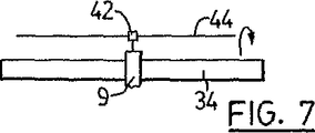
スクレーパ9は、管状部材を囲むことができる位置にスクレーパ9を支持するようになっている、管状部材に対して軸方向に移動させることができる手段と結び付けて取り付けられることを理解されたい。このことは、管状部材34と、ねじ山を付けられたねじ44に沿って長手方向に移動するようになっているキャリッジ部材42に連結されたスクレーパ9を示す図7に模式的に示されている。ねじ44を回転させると、キャリッジ42は(回転の向きに応じて)左へ、または右へ移動し、スクレーパ9を管状部材34の長手方向に搬送する。
【0033】
本発明の2つの実施形態を添付の図面に示し、上述したが、当業者が、添付の特許請求の範囲に記載されたような、本発明の本質から逸脱することなく、これらに変更および修正を行うことができるのは明白である。
【図面の簡単な説明】
【図1】 本発明の一実施形態の主要な部材の分解斜視図である。
【図2】 図1に示されている主要な部材の軸方向の分解断面図である。
【図3】 本発明の原理を示すために、(湾曲したワイヤから作られた)スクレーパ部材の1つの断片の理論的な配置を示す、各部品が図1および図2に示されている組み立てられたスクレーパの横断面図である。
【図4】 管状部材によってスクレーパ断片が所定の位置から外側へ湾曲させられ、したがって、内側への押圧力が生じ、ワイヤの断片によって管状部材の表面の一部を清掃することができる状態の、ジャケット部材の互いに揃えられた開口部を通過している管状部材の、図3と同様の横断面図である。
【図5】 ワイヤの複数の断片を示す、スクレーパの軸方向の図である。
【図6】 図2の保持部材に類似している、第2の実施形態の主要な保持部材の一部の軸方向の断面図である。
【図7】 管状部材と、スクレーパ部材と、スクレーパ部材を管状部材に沿って移動させる手段を示す模式的な側面図である。[0001]
FIELD OF THE INVENTION The present invention relates to a method and apparatus for preventing scale, deposits, etc. from remaining on the outer surface of a tubular member. The present invention is particularly suitable for, but not limited to, scraping and cleaning of protective quartz tubular members used during UV sterilization and / or disinfection of water and other liquids.
[0002]
Background of the invention It is well known to use ultraviolet light for the sterilization and / or disinfection of water. In addition, ultraviolet light can be used to perform other treatments and produce reactions on fluids including water and air. The ultraviolet light is usually obtained from a lamp in the form of a linear hollow tubular member, in particular a quartz tubular member, made of a material that transmits ultraviolet light. Electrical connections extend through the sealed end of the tubular member, and these electrical connections are protected from contact with the fluid.
[0003]
Scales, deposits, etc. tend to accumulate on the surface of the UV lamp, or where an outer sheath is used, especially after a continuous period of use. Scale and other sediment problems become partly severe when treating water. As scale and other deposits accumulate on the surface of the tubular member, the ultraviolet light from the lamp transmitted to the fluid is reduced. For this reason, the intensity of light is reduced, resulting in a reduction in processing efficiency and effectiveness. When treating water, it may be required to clean the outer surface of the tubular member weekly or daily, and possibly more frequently, depending on the quality of the water being treated.
[0004]
The tubular member can be cleaned by separating the tubular member from the fluid and scraping or chemical treatment. To this end, in a normal situation where a plurality of tubular members are used in a dense manner, it is necessary to partially disassemble the device and to extend the downtime of use of the device.
[0005]
Various methods have been developed to clean the tubular member using a brush, wiper, etc. without separating the tubular member from the fluid. One such system is disclosed in US Pat. No. 5,266,280 issued Nov. 30, 1993 to Hallett. In this system, a cylindrical UV transparent sheath is used to isolate the UV lamp from the internal space of the reaction vessel. The sheath is sealed to isolate the UV lamp from the fluid. A brush device is provided for brushing the outer surface of the sheath to remove deposited material from the fluid. The brush device has at least two brushes with rough hairs extending radially inward toward the sheath when surrounded by the brush. These brushes are connected to each other at intervals on the sheath together with a device that causes the brushes to reciprocate, preferably periodically along the outside of the sheath.
[0006]
U.S. Pat. No. 3,462,597 issued to Young on August 19, 1969 discloses a UV lamp system for purifying water, including a wiper system for a protective sheath surrounding the UV lamp. The wiper system has a wiper ring formed from Teflon ™ or similar material that is not affected by UV radiation. The rings are preferably spaced apart from each other and are split into springs so that they can be held elastically, i.e. elastically, on the outer surface of the protective tubular member. The wiper ring is connected to a ring holder engaged with a rod that extends through the end of the reactor. The ring holder is then reciprocated to perform a wiping action along the protective tubular member to remove physical or biological material deposited on the outside of the tubular member. However, this system is considered inadequate to cope with the dimensional variations of the protective tubular member, usually formed from quartz. In addition, using a wiper ring made of Teflon ™ fluoropolymer or similar materials, a) no sharp, hard scraping surfaces (like razors), b) the slipperiness typical of Teflon fluoropolymers Because of this, the quartz surface does not become clean.
[0007]
US Pat. No. 3,562,520 issued to Hippen in February 1971 discloses the use of a wiper system for routine cleaning of a protective quartz tubular member surrounding a UV lamp. The wiper system includes a plurality of ring-shaped wiper members that surround the outer surface of the protective tubular member and contact the outer surface for wiping. The wiper assembly is biased along the tubular member by a coil spring. As the water to be treated flows through the reactor, the wiper is returned toward the other end of the tubular member, and the area of the tubular member between the inlet and outlet is wiped off. It is described that the deposit can be removed from the protective tubular member each time the water purification device is started.
[0008]
U.S. Pat. No. 3,904,363 issued September 9th, 1975 to Free discloses a wiper system which is also operated by a stream of water. However, the protective tubular member is not cleaned while the water flow continues. The wiper system is moved to one end of the tubular member by the flow of water and held there. When the water is shut off, the wiper descends to the bottom of the reactor under the influence of gravity. The wiper system includes a flexible semi-rigid plastic or flexible metal film. This film may be a film formed in a brush shape made of a composite material or a plastic material. However, this membrane is very thin and often unsuitable for removing stubborn deposits on the protective sheath. Furthermore, plastic wipers degrade when subjected to intense UV radiation from high power lamps.
[0009]
The inability of the devices disclosed in US Pat. Nos. 3,562,520 and 3,904,363 to operate with a continuous flow of water protects the deposits as water continues to flow through the device. It means that it gradually accumulates on the tubular member. This reduces UV light transmission and, as a result, reduces the effectiveness of UV radiation during the treatment of bacteria.
[0010]
US Pat. No. 5,528,044 issued to Hutchinson on June 18, 1996 describes a wiper assembly having a rod that can be moved from the outside of the reaction vessel to mechanically reciprocate the wiper assembly. It is disclosed to use. The wiper assembly includes a plate having a plurality of radially extending fingers that engage the outer surface of a tubular member surrounding the lamp.
[0011]
Other patents include US Pat. No. 4,482,809, US Pat. No. 4,872,980, US Pat. No. 5,0062,444, and US Pat. No. 5,418,370, all issued to Maarschalkerweerd. In the devices described in the first three of these patents, the sleeve surrounding the UV lamp is periodically contaminated with foreign material, where manual cleaning is required to remove such material. In the last patent, by providing a cleaning device incorporating a cleaning sleeve that engages the outer part of the assembly of the radiation source and is movable between a retracted position and an extended position. This drawback is eliminated. The cleaning sleeve includes a chamber that contacts a portion of the radiation source, which is supplied with a cleaning solution suitable for removing unwanted material. Such cleaning methods and devices tend to be relatively complex and expensive.
[0012]
A simple and effective method and apparatus for cleaning the outer surface of the tubular member is advantageous.
[0013]
SUMMARY OF THE INVENTION In view of the aforementioned disadvantages of the prior art, one object of the present invention is to provide a scraper that removes deposits from the outer surface of a tubular member, such as a protective quartz sheath. is there.
[0014]
Accordingly, one aspect of the present invention is a scraper that removes deposits from the outside of a tubular member,
An outer jacket opening inwardly forming a recess located in the circumferential surface and two axially aligned openings;
A scraper in the form of an elongated elastic wire that is curved to form a series of unitary, tethered, elastic pieces, each pair of adjacent pieces connected by a knee-like curve. And having a member
The knee-shaped bend is placed in the recess with at least one piece extending substantially along the chords of the axial openings aligned with each other,
In order for the tubular member to pass through the axial openings aligned with each other, at least one piece needs to be deformed outward by the tubular member, so that the piece is inwardly tubular due to the elasticity of the deformed piece. Pressed against the member, whereby the tubular member provides a scraper that is cleaned as the scraper moves axially relative to the tubular member.
[0015]
Another aspect of the present invention is a method for removing deposits from the outer surface of a tubular member comprising:
A series of elastic pieces, adjacent to each other, with an inwardly-opening circumferential recess and an outer jacket forming two axially aligned openings And a scraper member in the form of an elongate elastic wire, curved to form a piece connected by a knee-like bend, wherein the bend is at least one piece aligned with each other. Forming a scraper that is encased in the recess in a state extending substantially along the string of the axial opening.
The tubular member is inserted into the aligned openings so as to deform at least one piece outwardly, whereby the piece is pressed against the tubular member inwardly by the elasticity of the deformed piece. Thereby cleaning the tubular member as the scraper moves axially relative to the tubular member.
[0016]
DETAILED DESCRIPTION OF THE INVENTION Two embodiments of the present invention are illustrated in the accompanying figures, wherein like reference numerals designate like parts throughout the several views.
[0017]
The present invention provides a scraper that removes deposits from the outer surface of a tubular member, such as a tubular quartz sheath. In this embodiment, the scraper includes a scraper member that contacts the tubular member. Such a scraper member may be in the form of an elongated elastic wire held in an outer jacket so that the pieces extend along the chords of the axial openings aligned with each other. In this way, the tubular member can only be passed through the opening by deforming this piece of wire outward. Each piece is pressed against the tubular member by the elasticity of each piece, and the surface of the tubular member is cleaned by moving the scraper longitudinally.
[0018]
First, referring to FIG. 1, four basic members of a
[0019]
Shown on the left side of FIG. 1 is an
[0020]
As best seen in FIG. 2, the
[0021]
The
[0022]
In FIG. 2, it is confused that each
[0023]
Returning to FIG. 1, the
[0024]
The
[0025]
As best seen in FIG. 5, as a result of bending an elastic elongated wire into the shape shown in FIG. 1, substantially all of the pieces of wire are aligned with each other formed by the
[0026]
To theoretically show what happens, reference is made to FIG. 3 where only a
[0027]
As already pointed out, FIG. 5 is a diagram showing the configuration of the scraper more accurately.
[0028]
It should be further pointed out that the number of wire fragments shown in FIG. 1 is much less than the actual number, which is about 100.
[0029]
In the embodiment shown in FIG. 6, the left side of the
[0030]
In this way, the
[0031]
In order to enhance the scraping function of the
[0032]
It should be understood that the
[0033]
While two embodiments of the invention have been illustrated and described above in the accompanying drawings, those skilled in the art will perceive changes and modifications therein without departing from the essence of the invention as set forth in the appended claims. It is clear that can be done.
[Brief description of the drawings]
FIG. 1 is an exploded perspective view of main members according to an embodiment of the present invention.
FIG. 2 is an exploded sectional view in the axial direction of main members shown in FIG. 1;
FIG. 3 shows the theoretical arrangement of one piece of scraper member (made from a curved wire), each part shown in FIGS. 1 and 2, to illustrate the principles of the present invention. It is a cross-sectional view of the obtained scraper.
FIG. 4 shows the scraper piece being curved outward from a predetermined position by the tubular member, thus creating an inward pressing force that allows the wire piece to clean a portion of the surface of the tubular member. FIG. 4 is a cross-sectional view similar to FIG. 3 of a tubular member passing through openings aligned with each other in a jacket member.
FIG. 5 is an axial view of a scraper showing a plurality of pieces of wire.
6 is an axial sectional view of a portion of a main holding member of a second embodiment, similar to the holding member of FIG.
FIG. 7 is a schematic side view showing a tubular member, a scraper member, and means for moving the scraper member along the tubular member.
Claims (10)
内側に向かって開いた、周面に位置する凹部および、一列に揃えられた、軸方向の2つの開口部を形成する外側のジャケットと、
一体につながれた、弾性を有する一連の断片であって、互いに隣接する該断片の対の各々が屈曲部によって連結された断片を形成するように屈曲した、弾性を有する細長いワイヤからなるスクレーパ部材とを有し、
前記屈曲部は、少なくとも1つの前記断片が、前記一列に揃えられた、軸方向の開口部の中の弦となる方向に延びている状態で前記凹部内に入れられ、
それによって、前記管状部材を、前記一列に揃えられた、軸方向の開口部に通すには、前記管状部材によって少なくとも1つの前記断片を外側に変形させる必要があり、その結果、前記断片は、変形させられた前記断片の弾性によって内側に前記管状部材に対して押し付けられ、それによって、前記管状部材は、前記スクレーパが前記管状部材に対して軸方向に移動する際に清掃されるスクレーパ。A scraper for removing deposits from the outer surface of the tubular member,
Open towards the inside, the recess and located on the peripheral surface, aligned in a row, and an outer jacket to form the two openings in the axial direction,
And flows together Nitsu, a series of fragments having elasticity and bent to form fragments each pair of the fragment are linked by bent portions adjacent to each other, the scraper member consisting of an elongated wire having elasticity And
The bent portion includes at least one of said fragments, said aligned in a row, in a state extending in a direction in which a chord in the axial opening placed in the recess,
Whereby, said tubular member, said aligned in a row, is passed through the opening in the axial direction, it is necessary to deform the at least one of said pieces by said tubular member outwardly, so that the fragment, A scraper that is pressed against the tubular member inwardly by the elasticity of the deformed piece, whereby the tubular member is cleaned as the scraper moves axially relative to the tubular member.
内側に向かって開いた、周面に位置する凹部および、一列に揃えられた、軸方向の2つの開口部を形成する、外側のジャケットと、一体につながれた、弾性を有する一連の断片であって、互いに隣接する該断片の対の各々が屈曲部によって連結された断片を形成するように湾曲した、弾性を有する細長いワイヤからなるスクレーパ部材とを含み、前記屈曲部は、少なくとも1つの前記断片が、前記一列に揃えられた、軸方向の開口部の中の弦となる方向に延びている状態で前記凹部内に入れられているスクレーパを形成することと、
少なくとも1つの前記断片を外側に変形さるように、前記管状部材を互いに揃えられた前記開口部に挿入し、これによって、前記断片は、変形させられた前記断片の弾性によって内側に前記管状部材に対して押し付けられ、それによって、前記管状部材を、前記スクレーパが前記管状部材に対して軸方向に移動する際に清掃することとを含む方法。A method of removing deposits from the outer surface of a tubular member,
Open towards the inside, the recess and located on the peripheral surface, aligned in a row to form two openings in the axial direction, and outer jacket, tethered together, there a set of fragments having elasticity Te, curved to form a fragment each pair of the fragment are linked by bent portions adjacent to each other, and a scraper member consisting of an elongated wire having elasticity, the bent portion, at least one of the fragments but forming a said aligned in a row, the axial direction of the scraper that is placed in the recess in a state extending in a direction in which a chord in the opening,
The tubular member is inserted into the openings aligned with each other so that at least one of the pieces is deformed outward, whereby the pieces are brought into the tubular member inwardly by the elasticity of the deformed pieces. Cleaning the tubular member as it is axially moved relative to the tubular member.
Applications Claiming Priority (3)
| Application Number | Priority Date | Filing Date | Title |
|---|---|---|---|
| CA2,306,546 | 2000-04-20 | ||
| CA002306546A CA2306546C (en) | 2000-04-20 | 2000-04-20 | Tube scraper |
| PCT/CA2000/000814 WO2001081019A1 (en) | 2000-04-20 | 2000-07-12 | Tube scraper |
Publications (3)
| Publication Number | Publication Date |
|---|---|
| JP2003531004A JP2003531004A (en) | 2003-10-21 |
| JP2003531004A5 JP2003531004A5 (en) | 2007-09-06 |
| JP4624634B2 true JP4624634B2 (en) | 2011-02-02 |
Family
ID=4165991
Family Applications (1)
| Application Number | Title | Priority Date | Filing Date |
|---|---|---|---|
| JP2001578104A Expired - Fee Related JP4624634B2 (en) | 2000-04-20 | 2000-07-12 | Scraper for tubular members |
Country Status (18)
| Country | Link |
|---|---|
| US (1) | US6432213B2 (en) |
| EP (1) | EP1274521B1 (en) |
| JP (1) | JP4624634B2 (en) |
| KR (1) | KR100496609B1 (en) |
| CN (1) | CN1265898C (en) |
| AT (1) | ATE281249T1 (en) |
| AU (2) | AU5958900A (en) |
| BR (1) | BR0017219B1 (en) |
| CA (1) | CA2306546C (en) |
| DE (1) | DE60015610T2 (en) |
| ES (1) | ES2232467T3 (en) |
| HK (1) | HK1049296B (en) |
| MX (1) | MXPA02010354A (en) |
| NO (1) | NO318484B1 (en) |
| NZ (1) | NZ521787A (en) |
| PL (1) | PL196286B1 (en) |
| RU (1) | RU2241553C2 (en) |
| WO (1) | WO2001081019A1 (en) |
Families Citing this family (42)
| Publication number | Priority date | Publication date | Assignee | Title |
|---|---|---|---|---|
| DE10125507A1 (en) * | 2001-05-23 | 2003-01-09 | Wedeco Ag | scraper |
| US6649917B2 (en) * | 2001-05-30 | 2003-11-18 | Ondeo Degremont | Cleaning system for UV disinfection module/reactor |
| EP1371611B1 (en) * | 2002-06-13 | 2007-03-21 | Malcolm Robert Snowball | Fluid Treatment apparatus |
| WO2004016586A2 (en) * | 2002-08-16 | 2004-02-26 | Board Of Regents The University Of Texas System | Compositions and methods related to flavivirus envelope protein domain iii antigens |
| FR2862010B1 (en) * | 2003-11-12 | 2006-06-16 | Otv Sa | DEVICE FOR CLEANING THE PROTECTIVE SHEATH OF UV LAMPS OF A DEVICE FOR DISINFECTING WATER BY ULTRAVIOLET RADIATION |
| FR2864814B1 (en) * | 2004-01-06 | 2007-02-02 | Rene Portalier | DEVICE FOR CLEANING A HANDLE AND TROLLEY COMPRISING SAME |
| FR2864813B3 (en) * | 2004-01-06 | 2006-03-17 | Rene Portalier | DEVICE FOR CLEANING A HANDLE AND TROLLEY COMPRISING SAME |
| GB0410607D0 (en) * | 2004-05-13 | 2004-06-16 | Snowball Malcolm R | Irradiation device |
| US7159264B2 (en) * | 2004-12-10 | 2007-01-09 | Calgon Carbon Corporation | Scraper for cleaning tubular members |
| US7275429B2 (en) * | 2005-04-06 | 2007-10-02 | Itt Manufacturing Enterprises Inc. | Mechanical self-cleaning probe via bi-metallic or shape memory |
| EP1882521A1 (en) * | 2006-07-28 | 2008-01-30 | Huei-Tarng Liou | Device for on-line light radiation in gas-containing liquid |
| US7780856B2 (en) * | 2006-07-28 | 2010-08-24 | Huei-Tarng Liou | Device for on-line light radiation in gas-containing liquid |
| US8336152B2 (en) * | 2007-04-02 | 2012-12-25 | C. R. Bard, Inc. | Insert for a microbial scrubbing device |
| US8065773B2 (en) * | 2007-04-02 | 2011-11-29 | Bard Access Systems, Inc. | Microbial scrub brush |
| US9192449B2 (en) | 2007-04-02 | 2015-11-24 | C. R. Bard, Inc. | Medical component scrubbing device with detachable cap |
| US8696820B2 (en) | 2008-03-31 | 2014-04-15 | Bard Access Systems, Inc. | Method of removing a biofilm from a surface |
| US8069523B2 (en) * | 2008-10-02 | 2011-12-06 | Bard Access Systems, Inc. | Site scrub brush |
| CA2757080C (en) | 2009-04-01 | 2017-03-14 | C. R. Bard, Inc. | Microbial scrubbing device |
| US8424150B1 (en) | 2009-06-11 | 2013-04-23 | Daniel Richard Higgins | Rod scraper |
| DE102009039655B3 (en) * | 2009-09-02 | 2011-03-31 | ITT Mfg. Enterprises, Inc., Wilmington | UV disinfection device for waste water and drinking water with a cleaning device |
| CN102311154B (en) * | 2010-07-01 | 2014-11-05 | 深圳市海川实业股份有限公司 | Sensor, cleaning device and ultraviolet disinfection equipment |
| CN102310056B (en) * | 2010-07-07 | 2014-03-12 | 株式会社日立建筑系统 | Spline lining cleaning device and assembling workpiece clamp |
| CN102172589A (en) * | 2011-02-23 | 2011-09-07 | 上海华钢不锈钢有限公司 | Device for cleaning stainless steel pipe by flexible films |
| DE102012103497A1 (en) * | 2012-04-20 | 2013-10-24 | Miele & Cie. Kg | dishwasher |
| DE102012103496A1 (en) * | 2012-04-20 | 2013-11-07 | Miele & Cie. Kg | dishwasher |
| CN103351035B (en) * | 2013-07-10 | 2014-12-17 | 上海船研环保技术有限公司 | Cleaning support structure of ultraviolet sterilizing device for water treatment |
| CN103351036B (en) * | 2013-07-10 | 2015-02-04 | 上海船研环保技术有限公司 | Cleaning support structure of ultraviolet sterilizing device for water treatment |
| EP3049834A1 (en) * | 2013-09-26 | 2016-08-03 | CGG Services SA | Device and methods for low contact cable cleaning |
| RU2605540C2 (en) * | 2015-01-12 | 2016-12-20 | Акционерное общество "Центральное конструкторское бюро машиностроения" (АО "ЦКБМ") | Method for automatic decontamination of rod fuel elements and device therefor |
| CN106269748B (en) * | 2016-08-30 | 2021-08-27 | 台州长天能源技术有限公司 | Column cleaning device driven by oblique roller |
| CN106269721B (en) * | 2016-08-31 | 2018-11-13 | 张家港市华扬冶金机械有限公司 | A kind of metal pipe outer wall derusting cleaning equipment |
| SE541117C2 (en) * | 2017-02-17 | 2019-04-09 | Wallenius Water Innovation Ab | A liquid treatment system comprising at least one ultra-violet (UV) treatment lamp |
| SE540414C2 (en) | 2017-02-17 | 2018-09-11 | Wallenius Water Innovation Ab | A liquid treatment system including a cleaning arrangement |
| RU2656500C1 (en) * | 2017-07-06 | 2018-06-05 | Рашид Ильмарович Бурнашев | Cleaning tool |
| CN108380540A (en) * | 2018-04-13 | 2018-08-10 | 上海宝冶集团有限公司 | It is a kind of to dissipate the method and tool that soil is cleared up to foundation pit steel support surface |
| CN113491382A (en) * | 2020-04-03 | 2021-10-12 | 深圳中标南方低碳经济标准化研究院有限公司东莞分公司 | Brush cleaner |
| CN111420944B (en) * | 2020-04-10 | 2021-04-13 | 浙江科技学院 | Rotary scraper machine |
| RU206071U1 (en) * | 2021-04-26 | 2021-08-18 | Михаил Маркович Дорошинский | DEVICE FOR CLEANING THE EXTERNAL SURFACE OF PIPES |
| CN113149376B (en) * | 2021-05-28 | 2021-12-31 | 江苏汇龙水务集团有限公司 | Domestic sewage VER treatment system |
| DK181491B1 (en) * | 2022-04-11 | 2024-03-07 | Rigtools Aps | System for pipe cleaning |
| CN115301640B (en) * | 2022-08-25 | 2023-11-17 | 上海友海建设工程有限公司 | Water conservancy construction pipeline surface rust cleaning device |
| CN116621287B (en) * | 2023-07-24 | 2023-09-22 | 中国市政工程西南设计研究总院有限公司 | Electrode bar self-cleaning device for sewage electrolytic purification treatment |
Family Cites Families (72)
| Publication number | Priority date | Publication date | Assignee | Title |
|---|---|---|---|---|
| US3138430A (en) | 1964-06-23 | J-sojh | ||
| US2732502A (en) | 1956-01-24 | darney | ||
| US1134342A (en) | 1915-04-06 | Charles Maier | Flue-cleaner. | |
| US1253363A (en) * | 1917-03-01 | 1918-01-15 | Charles A Farr | Printing-roller-cleaning device. |
| US1899379A (en) * | 1931-03-26 | 1933-02-28 | Ernest H Adams | Pipe cleaning machine |
| US2843168A (en) * | 1957-04-22 | 1958-07-15 | Edward O Lunn | Rotary-ring debarker having cablebiased springy-blade scrapers |
| US3061721A (en) | 1960-01-19 | 1962-10-30 | Brenner Al | Automatic tube cleaning device |
| US3182193A (en) | 1962-01-03 | 1965-05-04 | Ultra Dynamics Corp | Electronically monitored liquid purification or sterilizing system |
| US3138708A (en) | 1962-06-01 | 1964-06-23 | Ultra Dynamics Corp | Apparatus for ultraviolet irradiation of fluids |
| US3336099A (en) | 1963-01-23 | 1967-08-15 | Czulak Joseph | Apparatus for the sanitization of liquids with especial application to water storages and swimming pools |
| US3182191A (en) | 1963-02-14 | 1965-05-04 | Puretest Water Purifier Co | Water purifying apparatus with an automatically actuated wiper for the ultra-violet source |
| US3456107A (en) | 1967-05-16 | 1969-07-15 | Aquacare Intern Ltd | Water sterilizing apparatus |
| US3485576A (en) | 1967-06-29 | 1969-12-23 | Ionics | Ultraviolet process and apparatus for disinfection of aqueous liquids |
| US3562520A (en) | 1968-11-04 | 1971-02-09 | Puretest Water Purifying Co | Fail-safe water purifying apparatus |
| FR2045155A5 (en) * | 1969-06-10 | 1971-02-26 | Tractel Sa | |
| US3634025A (en) | 1969-11-20 | 1972-01-11 | Alfred Landry | Water sterilizer |
| DE2003989A1 (en) | 1970-01-29 | 1971-08-05 | Rauh Apparatebau D | Ultraviolet irradiation sterilizer for conti |
| US3837800A (en) | 1971-05-06 | 1974-09-24 | Meltzer H | Method and apparatus for purifying fluids |
| CA966608A (en) | 1972-11-20 | 1975-04-29 | Naturvard Research (Canada) Ltd. | Automatic tube cleaner for water sterilizer |
| US3844661A (en) | 1973-02-14 | 1974-10-29 | Gen Atomic Co | Self-cleaning optical cell for a fluid analysis system |
| US4017734A (en) | 1974-09-27 | 1977-04-12 | Ross Henry M | Water purification system utilizing ultraviolet radiation |
| DE2515604C2 (en) | 1975-04-10 | 1977-06-08 | Alfred Graentzel | APPARATUS FOR RADIATION OF FLOW CAPABLE MEDIA TO ACHIEVE CHEMICAL REACTIONS AND REACTION PRODUCTS |
| DE2549321A1 (en) * | 1975-11-04 | 1977-05-12 | Gottfried Baumann | Strip metal coil with angled bends - having polygonal profile formed from strip continually bent at regular angle |
| US4102645A (en) | 1976-06-23 | 1978-07-25 | Refreshment Machinery Incorporated | Sterilization apparatus |
| US4103167A (en) | 1976-08-16 | 1978-07-25 | Sidney Ellner | Ultraviolet liquid purification system |
| DE2733344C2 (en) | 1977-07-23 | 1979-07-12 | Alfred 7500 Karlsruhe Graentzel | Apparatus for irradiating flowable media to achieve chemical reactions or reaction products |
| JPS54136761U (en) * | 1978-03-14 | 1979-09-21 | ||
| US4151085A (en) | 1978-04-03 | 1979-04-24 | Malik Lionel W | Water purification system |
| US4358204A (en) | 1980-09-22 | 1982-11-09 | Sidney Ellner | Ultrasonic cleaning apparatus |
| GB2152184B (en) | 1983-11-30 | 1986-02-12 | Ae Plc | Oil scraper rings |
| US4752401A (en) | 1986-02-20 | 1988-06-21 | Safe Water Systems International, Inc. | Water treatment system for swimming pools and potable water |
| US4849100A (en) | 1986-03-07 | 1989-07-18 | North American Aqua | Portable water purifier |
| US4728368A (en) | 1986-04-25 | 1988-03-01 | Pedziwiatr Edward A | Ultrasonic cleaning in liquid purification systems |
| US4766321A (en) | 1986-05-27 | 1988-08-23 | Jung G. Lew | Symbiotic filter-sterilizer |
| DE3710250C3 (en) | 1987-03-28 | 1993-11-18 | Ultralight Ag Schaanwald | Device for disinfecting water by UV radiation |
| US4899056A (en) | 1988-07-07 | 1990-02-06 | Ultraviolet Purification Systems, Inc. | Cleaning system for ultraviolet light producing lamps |
| US4968489A (en) | 1988-09-13 | 1990-11-06 | Peroxidation Systems, Inc. | UV lamp enclosure sleeve |
| US4940902A (en) | 1988-10-24 | 1990-07-10 | Emmanuel Mechalas | Apparatus and method for continuous measurement of suspended solids in a liquid medium with wiping means |
| US4922114A (en) | 1989-06-01 | 1990-05-01 | Hilary Boehme | Wiper mechanism |
| US5005245A (en) | 1989-10-12 | 1991-04-09 | Atlantic Richfield Company | Pipe coating removal system |
| US5085016A (en) * | 1990-01-26 | 1992-02-04 | E. B. Thomas | Method and apparatus for cleaning pipe |
| US5227140A (en) | 1990-04-13 | 1993-07-13 | Peroxidation Systems, Inc. | Modular self-cleaning oxidation chamber |
| NL9001605A (en) | 1990-07-16 | 1992-02-17 | Berson Milieutech | STERILIZATION DEVICE. |
| US5185533A (en) | 1991-09-03 | 1993-02-09 | Nalco Chemical Company | Monitoring film fouling in a process stream with a transparent shunt and light detecting means |
| US5185531A (en) | 1991-09-26 | 1993-02-09 | Wedgewood Technology, Inc. | Window cleaner for inline optical sensors |
| US5151252A (en) | 1991-10-17 | 1992-09-29 | Purus, Inc. | Chamber design and lamp configuration for an ultraviolet photochemical reactor |
| US5247178A (en) | 1991-12-12 | 1993-09-21 | Fusion Systems Corporation | Method and apparatus for treating fluids by focusing reflected light on a thin fluid layer |
| US5372781A (en) | 1992-02-18 | 1994-12-13 | Solarchem Enterprises Inc. | UV reactor assembly with improved lamp cooling means |
| DE4213021A1 (en) | 1992-04-21 | 1993-10-28 | Peter Ueberall | Cleaning turbine for quartz sheath tube of UV radiation channel for sewage - has water driven rotor surrounding tube and having brushes which clean tube surface as turbine is traversed along tube by arm and returned to parking position |
| US5332388A (en) | 1992-12-04 | 1994-07-26 | Infilco Degremont, Inc. | Ultraviolet disinfection module |
| US5418370A (en) | 1993-03-05 | 1995-05-23 | Trojan Technologies, Inc. | Fluid treatment system and process |
| CA2239925C (en) | 1993-03-05 | 2000-01-18 | Trojan Technologies Inc. | Fluid treatment system and process |
| US5620642A (en) | 1993-03-05 | 1997-04-15 | Misawa Homes Co., Ltd. | Simulated wood product manufacturing method and simulated wood product |
| CA2173472A1 (en) | 1993-10-06 | 1995-04-13 | Malcolm Robert Snowball | Uv apparatus for fluid treatment |
| US5440131A (en) | 1994-07-21 | 1995-08-08 | Solar Kinetics Inc. | Wiper assembly for ultraviolet-light reactor tubes |
| US5501843A (en) * | 1994-10-14 | 1996-03-26 | Vulcan Peroxidation Systems, Inc. | Wiper cartridge |
| US5504335A (en) | 1994-10-17 | 1996-04-02 | Trojan Technologies, Inc. | Fluid treatment device and method |
| US5539209A (en) | 1994-10-17 | 1996-07-23 | Trojan Technologies Inc. | Method of cleaning fouling materials from a radiation module |
| CA2160730C (en) | 1994-10-17 | 1999-12-21 | Jan M. Maarschalkerweerd | Method of cleaning fouling materials from a radiation module |
| US5534142A (en) | 1994-11-25 | 1996-07-09 | Vulcan Peroxidation Systems, Inc. | Flow-reversing system for series connected reaction chambers |
| US5660719A (en) | 1994-12-23 | 1997-08-26 | Kurtz; Mark E. | Ultraviolet light apparatus for fluid purification |
| FR2729382B1 (en) | 1995-01-16 | 1997-03-28 | Omnium Traitement Valorisa | UV IRRADIATION REACTOR FOR THE TREATMENT OF LIQUIDS |
| US5792433A (en) | 1995-03-13 | 1998-08-11 | Photoscience Japan Corporation | Light irradiating device with easily replaceable light irradiating lamps |
| US5528044A (en) | 1995-04-28 | 1996-06-18 | Solar Kinetics, Inc. | Wiper assembly for ultraviolet-light reactor tubes |
| US5625194A (en) | 1995-10-20 | 1997-04-29 | Phillips Petroleum Company | Continuous cleaning of lamp wells for ultraviolet (UV) light producing lamps |
| US5937266A (en) | 1996-03-08 | 1999-08-10 | Photoscience Japan Corporation | Light irradiating device employing light irradiating modules equipped with a cleaning mechanism |
| US5874740A (en) | 1996-03-14 | 1999-02-23 | Photoscience Japan Corporation | Ultraviolet ray irradiation equipment having scraper rings fitted to light transmission tubes |
| DE29608441U1 (en) | 1996-05-09 | 1996-08-01 | Dueker Eisenwerk | Plant for the disinfection of flowing media, such as water |
| DE19653083B4 (en) | 1996-12-19 | 2005-09-08 | Wedeco Ag Water Technology | Streamlined UV disinfection device |
| US6342188B1 (en) | 1998-11-03 | 2002-01-29 | Trojan Technologies, Inc. | Radiation source module and cleaning apparatus therefor |
| US6646269B1 (en) | 1999-02-26 | 2003-11-11 | Trojan Technologies, Inc. | Radiation source module and cleaning apparatus therefor |
| WO2000073212A1 (en) | 1999-05-27 | 2000-12-07 | Nilfisk-Advance A/S | A method of removing dirt from a dirty solution, use of the method and devices able to perform this method |
-
2000
- 2000-04-20 CA CA002306546A patent/CA2306546C/en not_active Expired - Fee Related
- 2000-07-12 AT AT00945497T patent/ATE281249T1/en not_active IP Right Cessation
- 2000-07-12 PL PL357649A patent/PL196286B1/en not_active IP Right Cessation
- 2000-07-12 AU AU5958900A patent/AU5958900A/en active Pending
- 2000-07-12 AU AU2000259589A patent/AU2000259589B2/en not_active Ceased
- 2000-07-12 KR KR10-2002-7014083A patent/KR100496609B1/en not_active IP Right Cessation
- 2000-07-12 RU RU2002131162/12A patent/RU2241553C2/en not_active IP Right Cessation
- 2000-07-12 ES ES00945497T patent/ES2232467T3/en not_active Expired - Lifetime
- 2000-07-12 WO PCT/CA2000/000814 patent/WO2001081019A1/en active IP Right Grant
- 2000-07-12 EP EP00945497A patent/EP1274521B1/en not_active Expired - Lifetime
- 2000-07-12 BR BRPI0017219-7A patent/BR0017219B1/en not_active IP Right Cessation
- 2000-07-12 CN CNB008194505A patent/CN1265898C/en not_active Expired - Fee Related
- 2000-07-12 NZ NZ521787A patent/NZ521787A/en not_active IP Right Cessation
- 2000-07-12 JP JP2001578104A patent/JP4624634B2/en not_active Expired - Fee Related
- 2000-07-12 DE DE60015610T patent/DE60015610T2/en not_active Expired - Lifetime
- 2000-07-12 MX MXPA02010354A patent/MXPA02010354A/en active IP Right Grant
-
2001
- 2001-02-27 US US09/794,654 patent/US6432213B2/en not_active Expired - Lifetime
-
2002
- 2002-10-18 NO NO20025032A patent/NO318484B1/en not_active IP Right Cessation
-
2003
- 2003-02-24 HK HK03101384.9A patent/HK1049296B/en not_active IP Right Cessation
Also Published As
| Publication number | Publication date |
|---|---|
| PL357649A1 (en) | 2004-07-26 |
| BR0017219A (en) | 2003-03-05 |
| CA2306546A1 (en) | 2001-10-20 |
| AU2000259589B2 (en) | 2004-12-23 |
| PL196286B1 (en) | 2007-12-31 |
| NO20025032D0 (en) | 2002-10-18 |
| US6432213B2 (en) | 2002-08-13 |
| JP2003531004A (en) | 2003-10-21 |
| WO2001081019A1 (en) | 2001-11-01 |
| MXPA02010354A (en) | 2004-09-06 |
| HK1049296B (en) | 2005-05-13 |
| NZ521787A (en) | 2003-05-30 |
| KR20030001441A (en) | 2003-01-06 |
| KR100496609B1 (en) | 2005-06-22 |
| CA2306546C (en) | 2006-06-27 |
| ES2232467T3 (en) | 2005-06-01 |
| DE60015610D1 (en) | 2004-12-09 |
| ATE281249T1 (en) | 2004-11-15 |
| US20010032659A1 (en) | 2001-10-25 |
| AU5958900A (en) | 2001-11-07 |
| AU2000259589A1 (en) | 2002-01-24 |
| EP1274521A1 (en) | 2003-01-15 |
| RU2002131162A (en) | 2004-03-20 |
| CN1452523A (en) | 2003-10-29 |
| NO20025032L (en) | 2002-12-18 |
| BR0017219B1 (en) | 2010-06-15 |
| NO318484B1 (en) | 2005-03-29 |
| CN1265898C (en) | 2006-07-26 |
| RU2241553C2 (en) | 2004-12-10 |
| EP1274521B1 (en) | 2004-11-03 |
| DE60015610T2 (en) | 2005-11-10 |
| HK1049296A1 (en) | 2003-05-09 |
Similar Documents
| Publication | Publication Date | Title |
|---|---|---|
| JP4624634B2 (en) | Scraper for tubular members | |
| KR101270325B1 (en) | Scraper for cleaning tubular members | |
| US5528044A (en) | Wiper assembly for ultraviolet-light reactor tubes | |
| AU1910295A (en) | Wiper cartridge | |
| EP3583070B1 (en) | A liquid treatment system | |
| EP3583071B1 (en) | A liquid treatment system | |
| US20230025794A1 (en) | Cleaning arrangement for a liquid treatment system |
Legal Events
| Date | Code | Title | Description |
|---|---|---|---|
| A521 | Request for written amendment filed |
Free format text: JAPANESE INTERMEDIATE CODE: A523 Effective date: 20070712 |
|
| A621 | Written request for application examination |
Free format text: JAPANESE INTERMEDIATE CODE: A621 Effective date: 20070712 |
|
| RD03 | Notification of appointment of power of attorney |
Free format text: JAPANESE INTERMEDIATE CODE: A7423 Effective date: 20070712 |
|
| A131 | Notification of reasons for refusal |
Free format text: JAPANESE INTERMEDIATE CODE: A131 Effective date: 20100224 |
|
| A521 | Request for written amendment filed |
Free format text: JAPANESE INTERMEDIATE CODE: A523 Effective date: 20100421 |
|
| TRDD | Decision of grant or rejection written | ||
| A01 | Written decision to grant a patent or to grant a registration (utility model) |
Free format text: JAPANESE INTERMEDIATE CODE: A01 Effective date: 20101006 |
|
| A01 | Written decision to grant a patent or to grant a registration (utility model) |
Free format text: JAPANESE INTERMEDIATE CODE: A01 |
|
| A61 | First payment of annual fees (during grant procedure) |
Free format text: JAPANESE INTERMEDIATE CODE: A61 Effective date: 20101104 |
|
| R150 | Certificate of patent or registration of utility model |
Free format text: JAPANESE INTERMEDIATE CODE: R150 |
|
| FPAY | Renewal fee payment (event date is renewal date of database) |
Free format text: PAYMENT UNTIL: 20131112 Year of fee payment: 3 |
|
| R250 | Receipt of annual fees |
Free format text: JAPANESE INTERMEDIATE CODE: R250 |
|
| R250 | Receipt of annual fees |
Free format text: JAPANESE INTERMEDIATE CODE: R250 |
|
| R250 | Receipt of annual fees |
Free format text: JAPANESE INTERMEDIATE CODE: R250 |
|
| R250 | Receipt of annual fees |
Free format text: JAPANESE INTERMEDIATE CODE: R250 |
|
| R250 | Receipt of annual fees |
Free format text: JAPANESE INTERMEDIATE CODE: R250 |
|
| LAPS | Cancellation because of no payment of annual fees |