JP4919059B2 - Stator for rotating electrical machine and method for manufacturing the same - Google Patents
Stator for rotating electrical machine and method for manufacturing the same Download PDFInfo
- Publication number
- JP4919059B2 JP4919059B2 JP2007169325A JP2007169325A JP4919059B2 JP 4919059 B2 JP4919059 B2 JP 4919059B2 JP 2007169325 A JP2007169325 A JP 2007169325A JP 2007169325 A JP2007169325 A JP 2007169325A JP 4919059 B2 JP4919059 B2 JP 4919059B2
- Authority
- JP
- Japan
- Prior art keywords
- stator
- slot
- rotating electrical
- electrical machine
- circumferential direction
- Prior art date
- Legal status (The legal status is an assumption and is not a legal conclusion. Google has not performed a legal analysis and makes no representation as to the accuracy of the status listed.)
- Active
Links
Images


Classifications
-
- Y—GENERAL TAGGING OF NEW TECHNOLOGICAL DEVELOPMENTS; GENERAL TAGGING OF CROSS-SECTIONAL TECHNOLOGIES SPANNING OVER SEVERAL SECTIONS OF THE IPC; TECHNICAL SUBJECTS COVERED BY FORMER USPC CROSS-REFERENCE ART COLLECTIONS [XRACs] AND DIGESTS
- Y02—TECHNOLOGIES OR APPLICATIONS FOR MITIGATION OR ADAPTATION AGAINST CLIMATE CHANGE
- Y02T—CLIMATE CHANGE MITIGATION TECHNOLOGIES RELATED TO TRANSPORTATION
- Y02T10/00—Road transport of goods or passengers
- Y02T10/60—Other road transportation technologies with climate change mitigation effect
- Y02T10/64—Electric machine technologies in electromobility
Landscapes
- Windings For Motors And Generators (AREA)
- Manufacture Of Motors, Generators (AREA)
Description
本発明は、回転電機のステータ及びその製造方法に関し、好適にはハイブリッド車や電気自動車駆動用回転電機のステータ及びその製造方法に関する。 The present invention relates to a stator for a rotating electrical machine and a method for manufacturing the same, and preferably relates to a stator for a rotating electrical machine for driving a hybrid vehicle or an electric vehicle and a method for manufacturing the same.
近年、ハイブリッド車の回転電機は、燃費向上と車両搭載上の制約からモータの小型化が可能なステータおよびその製造技術が望まれている。小型化のためには、ステータ巻線(導体)のスロット占積率を高くすること、また、コイルエンド突出量を減らすことが望まれている。従来のステータ(特許文献1参照)を図12に示す。なお、図12に示す符号は、後述する本発明の実施形態を説明する他図の符号とは無関係である。図12において、高占積率を得るために、ステータ巻線は、平角線を径方向に整列配置し、予め環状に巻回した整形コイルをステータコアに収容する手法が採用されている。この整形コイルは、あらかじめ整列状態で織込まれた軸方向突出長が短いコイルエンドをもつ。図12では、この整形コイルをステータコアに収容するために整形コイルの外周側に環状配置された複数の分割コアを縮径方向に移動させる手法が採用されている。
予め整形された整形コイルをステータコアのスロットに収容する上記のステータの製造方法によれば、ステータ巻線を高占積率、低コイルエンドとすることができる。しかしながら、図12に示す分割コアからなるステータコアを高トルク仕様で磁束量も多い車両駆動用モータに適用した場合、コアバック(継鉄)が1スロット間隔で分割されるため、磁気抵抗の増大により磁束量の低下やトルク低下を生じさせ、回転電機の小型化を阻害するという問題点があった。 According to the above-described stator manufacturing method in which the preshaped coil is accommodated in the stator core slot, the stator winding can have a high space factor and a low coil end. However, when the stator core composed of the split cores shown in FIG. 12 is applied to a vehicle drive motor having a high torque specification and a large amount of magnetic flux, the core back is divided at 1-slot intervals. There has been a problem in that the amount of magnetic flux is reduced and the torque is reduced, and the miniaturization of the rotating electrical machine is hindered.
本発明は上記事情に鑑みてなされたもので、磁気抵抗の増大を抑止し且つコア分割も不要であり、高占積率及び低コイルエンド化が可能な回転電機のステータ及びその製造方法を提供することをその目的としている。 The present invention has been made in view of the above circumstances, and provides a stator for a rotating electrical machine that suppresses an increase in magnetic resistance, does not require a core division, and can achieve a high space factor and a low coil end, and a method for manufacturing the same. Its purpose is to do.
本発明による回転電機のステータは、スロット及びティースが周方向交互に形成された円筒状のステータコアと、前記スロットに収容されたステータ巻線とを備える回転電機のステータにおいて、前記ステータ巻線は、周方向略磁極ピッチ離れた2つの前記スロットに個別に収容される1対のスロット収容部と、前記ステータコアの軸方向外側にて前記1対のスロット収容部を接続するターン部とを有し、前記ステータ巻線は、互いに面接触状態にて積層され且つそれぞれ樹脂被膜により絶縁被覆されて互いに平行に延在する複数の導体素線と、前記複数の導体素線を囲包する樹脂被覆部とを有する厚被膜積層線により構成されており、前記ターン部の端部は、前記スロットの端部に位置する前記スロット収容部の端部から前記ティースの端面に沿いつつ周方向へ延在するクランク部を有し、前記ターン部は、周方向へ延在するとともに前記厚被膜積層線1本分に略等しい幅だけ径方向へ斜行する頭頂部を有していることをその特徴としている。 A stator of a rotating electrical machine according to the present invention is a stator of a rotating electrical machine including a cylindrical stator core in which slots and teeth are alternately formed in the circumferential direction, and a stator winding accommodated in the slot. A pair of slot accommodating portions individually accommodated in the two slots spaced apart from each other by a substantially magnetic pole pitch in the circumferential direction, and a turn portion connecting the pair of slot accommodating portions on the outer side in the axial direction of the stator core, The stator winding includes a plurality of conductor strands laminated in a surface contact state with each other and insulated and coated with a resin coating, respectively, and a resin coating portion surrounding the plurality of conductor strands. is constituted by a thick film multilayer line having an end portion of the turn portion, the end of the teeth from the end of the slot portion situated at the end of the slot Has a crank portion extending in the circumferential direction while along, the turn portion may have a top portion that obliquely only in the radial direction width substantially equal to the thickness coating layered lines one roll with extending in the circumferential direction It is characterized by that.
本発明によれば、導体を複数の導体素線に細分化したことによりステータ巻線の剛性を低下させることができるため、ターン部を容易に撓ませることができる。このため、ステータ巻線の電流容量を大きくするためその合計導体断面積を大きくする場合でも、予め円筒状に形成されたステータ巻線を縮径状態としてステータコアの内周側に配置し、その後、スロット収容部をステータコアの径方向内側からスロット内に挿入する作業を容易化することができる。また、ステータ巻線の良好な弾性変形性を利用して、非分割のステータコアの径方向内側に整形コイルを挿入し、ステータ巻線のスロット収容部をスロットに径方向に押し込むことができるため、コア分割が不要になり、磁気抵抗を増大させることがなく、高占積率で低コイルエンド化に適した巻線が可能になる。
また、ターン部の両端部に連なる一対のスロット収容部間に必要な径方向位置のずれをターン部の頭頂部により実現できる。したがって、ステータコア端面から頭頂部の先端までのターン部の軸方向突出長に相当するコイルエンドの高さを低減することができる。また、ターン部の頭頂部以外の部分は周方向及び軸方向に延在すればよく、ターン部の曲げ加工が容易となる。
According to the present invention, since the rigidity of the stator winding can be reduced by subdividing the conductor into a plurality of conductor strands, the turn portion can be easily bent. For this reason, even when the total conductor cross-sectional area is increased in order to increase the current capacity of the stator winding, the stator winding formed in a cylindrical shape in advance is disposed on the inner peripheral side of the stator core in a reduced diameter state, and then The operation of inserting the slot accommodating portion into the slot from the radially inner side of the stator core can be facilitated. Further, by utilizing the good elastic deformability of the stator winding, a shaping coil can be inserted inside the non-divided stator core in the radial direction, and the slot accommodating portion of the stator winding can be pushed into the slot in the radial direction. There is no need for core division, the magnetic resistance is not increased, and a winding suitable for low coil end can be achieved with a high space factor.
Further, a necessary radial position shift between the pair of slot accommodating portions connected to both ends of the turn portion can be realized by the top of the turn portion. Therefore, it is possible to reduce the height of the coil end corresponding to the axial protruding length of the turn portion from the stator core end surface to the tip of the top. Further, the portion other than the top portion of the turn portion only needs to extend in the circumferential direction and the axial direction, and bending of the turn portion is facilitated.
好適な態様において、前記複数の導体素線は、前記スロット内にて少なくとも周方向へ積層され且つ短辺が周方向へ延在する長方形断面形状を有する。つまり、この態様では、複数の導体素線は、スロット内にて少なくとも周方向へ積層され且つ積層方向に偏平な断面形状を有する。そのため、厚被膜積層線の周方向の曲げ剛性を低下させることができ、ターン部を周方向へ曲げ加工することが容易となる。したがって、ステータ巻線をステータコアの内周側で巻回した縮径状態としてから、スロット収容部をスロット位置まで移動させる挿入工程が容易にできる。 In a preferred aspect, the plurality of conductor strands have a rectangular cross-sectional shape that is laminated at least in the circumferential direction in the slot and has a short side extending in the circumferential direction. That is, in this aspect, the plurality of conductor strands have a cross-sectional shape that is laminated at least in the circumferential direction in the slot and flat in the lamination direction. Therefore, the bending rigidity in the circumferential direction of the thick film laminated wire can be reduced, and the turn part can be easily bent in the circumferential direction. Therefore, the insertion step of moving the slot accommodating portion to the slot position after the diameter of the stator winding is reduced on the inner peripheral side of the stator core can be facilitated.
好適な態様において、前記複数の導体素線は、前記スロット内にて少なくとも径方向へ積層され且つ短辺が径方向へ延在する長方形断面形状を有する。つまり、この態様では、複数の導体素線は、スロット内にて少なくとも径方向へ積層され且つ積層方向に偏平な断面形状を有する。そのため、厚被膜積層線の径方向の曲げ剛性を低下させることができ、厚被膜積層線の径方向寸法を大きくしてもターン部を径方向へ曲げ加工することが容易となる。したがって、厚被膜積層線の径方向寸法を増やすだけで大電流仕様に対応することができる。 In a preferred aspect, the plurality of conductor wires have a rectangular cross-sectional shape in which at least a radial direction is laminated in the slot and a short side extends in the radial direction. In other words, in this aspect, the plurality of conductor wires have a cross-sectional shape that is laminated at least in the radial direction in the slot and flat in the lamination direction. Therefore, the bending rigidity in the radial direction of the thick film laminated wire can be reduced, and the turn portion can be easily bent in the radial direction even if the radial dimension of the thick film laminated wire is increased. Therefore, it is possible to meet the large current specification only by increasing the radial dimension of the thick film laminated wire.
好適な態様において、前記複数の導体素線は、スロット内にて周方向及び径方向へ延在する側面を有して径方向及び周方向の両方へ整列して積層された平角線によりそれぞれ構成されている。これにより、厚被膜積層線の周方向の曲げ剛性を低下させることができ、ターン部を周方向へ撓ませることが容易になる。したがって、ステータ巻線をステータコアの内周側で巻回した縮径状態としてから、スロット収容部をスロット位置まで移動させる挿入工程が容易にできる。そのうえ、高いスロット占積率を実現することができる。 In a preferred aspect, each of the plurality of conductor strands is configured by a rectangular wire having side surfaces extending in the circumferential direction and the radial direction in the slot and stacked in alignment in both the radial direction and the circumferential direction. Has been. Thereby, the bending rigidity of the circumferential direction of a thick film laminated line can be reduced, and it becomes easy to bend a turn part to the circumferential direction. Therefore, the insertion step of moving the slot accommodating portion to the slot position after the diameter of the stator winding is reduced on the inner peripheral side of the stator core can be facilitated. Moreover, a high slot space factor can be realized.
好適な態様において、前記樹脂被膜は、100〜170μmの厚さを有する。これにより、部分放電の抑止に必要な絶縁被膜厚(100〜170μm)を安定して確保できる。 In a preferred embodiment, the resin coating has a thickness of 100 to 170 μm. Thereby, the insulation film thickness (100-170 micrometers) required for suppression of partial discharge can be ensured stably.
好適な態様において、前記樹脂被覆部は、押出し成形されて形成されている。これにより、サージ電圧による相間の部分放電(コロナ放電)の発生を相間絶縁紙なしに抑止できる。 In a preferred aspect, the resin coating portion is formed by extrusion molding. Thereby, generation | occurrence | production of the partial discharge (corona discharge) between phases by a surge voltage can be suppressed without interphase insulating paper.
好適な態様において、前記樹脂被膜は、内側に形成されて前記樹脂被膜をなす内層絶縁被膜と、前記内層絶縁被膜を被覆して前記樹脂被覆部をなす外層絶縁被膜とからなり、前記外層絶縁被膜は、前記内層絶縁被膜よりも低いガラス転移温度を有する。これにより、高温時に内層絶縁被膜より先に外層絶縁被膜が軟化して同一スロット内の線材どうしが熱接着し、径方向に整列して一体化するため、機械強度を向上させることができる。 In a preferred embodiment, the resin film is formed of an inner layer insulating film that is formed on the inner side to form the resin film, and an outer layer insulating film that covers the inner layer insulating film to form the resin coating portion, and the outer layer insulating film Has a glass transition temperature lower than that of the inner insulating film. As a result, the outer layer insulating film is softened prior to the inner layer insulating film at a high temperature, and the wires in the same slot are thermally bonded to each other and aligned in the radial direction, thereby improving the mechanical strength.
好適な態様において、前記スロットの内壁面は、絶縁性樹脂層により被覆されている。このため、従来のスロット絶縁紙を無くすことが出来、ステータ巻線のスロット収容部との組付けが容易になる。 In a preferred embodiment, the inner wall surface of the slot is covered with an insulating resin layer. For this reason, the conventional slot insulation paper can be eliminated, and the assembly with the slot accommodating part of a stator winding becomes easy.
好適な態様において、前記絶縁性樹脂層は、電着塗装により形成されている。このため、絶縁性樹脂層が厚くなり過ぎることがなく、コイルの占積率を向上できる。 In a preferred embodiment, the insulating resin layer is formed by electrodeposition coating. For this reason, the insulating resin layer does not become too thick, and the space factor of the coil can be improved.
本発明の回転電機のステータの製造方法によれば、上記ステータは、前記スロットに径方向に挿入可能に予め形成された円筒状の整形コイルを作製し、前記整形コイルを縮径してステータコアのロータ配置位置にセットし、前記整形コイルのスロット収容部を径方向外側に付勢して前記ステータコアの各スロットに収容して前記ステータ巻線を構成する組み付け方法を採用する。これにより、ステータコイルの組み付けを大幅に簡素化することができ、ステータコアの分割も不要となる。 According to the method for manufacturing a stator for a rotating electrical machine of the present invention, the stator is formed with a cylindrical shaping coil formed in advance so as to be insertable in the slot in the radial direction. An assembly method is adopted in which the stator winding is configured by setting the rotor coil at the rotor arrangement position, and energizing the slot accommodating portion of the shaping coil radially outward to accommodate the slot of the stator core. As a result, the assembly of the stator coil can be greatly simplified, and the division of the stator core becomes unnecessary.
以下、本発明の実施形態を図面に基づいて説明する。 Hereinafter, embodiments of the present invention will be described with reference to the drawings.
(第1実施形態)
(ステータの基本構造)
本発明の第1実施形態によるステータの基本構造を図5を参照して説明する。11はステータ、12はステータコア、13はステータコア12の端面、20はステータ巻線、hはステータ巻線20のコイルエンドの軸方向突出長(コイルエンド高さ)である。
(First embodiment)
(Basic structure of stator)
The basic structure of the stator according to the first embodiment of the present invention will be described with reference to FIG. 11 is a stator, 12 is a stator core, 13 is an end face of the
ステータ11は車両駆動用発電電動機に使用されるものであり、ステータ11の径方向内側には図略のロータが回転自在に収容される。このロータの外周部には、極性が周方向交互に異なる多数の磁極が永久磁石によって形成されている。ロータの外周面は、ステータ11の内周面に対して微小なエアギャップを介して対面している。ステータコア12は、所定厚さの電磁鋼板を軸方向に積層している。ステータ巻線20は3相巻線であり、スロット14には第1相の波巻巻線が巻装され、スロット15にも第1相の波巻巻線が巻装されている。つまり、互いに隣接する2つのスロット14、15(図6参照)に同相のステータ巻線20が巻装されいわゆる毎極毎相2スロット構成となっている。ステータ巻線20とステータコア12との間の電気絶縁性を確保するため、スロット14、15内壁にはスロット絶縁紙80が設けられている(図2参照)。
The
(線材30)
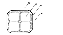
ステータ巻線20の線材30の構造について、図4を参照して説明する。
(Wire 30)
The structure of the
ステータ巻線20の線材30は、銅を素材とする4本の矩形断面形状の導体素線32により構成されている。各導体素線32の外周面は樹脂製の内層絶縁被膜34にて覆われ、更にそれらを囲覆して樹脂製の外層絶縁被膜36が形成され、最終的に一本の線材30となっている。4本の導体素線32はそれぞれ略正方形の平角線であって、それらの矩形断面の辺が2つの内層絶縁被膜34を挟んで互いに正対するように整列して配置されている。なお、各導体素線32が長方形の場合には、その長辺同士が正対し、短辺同士が正対するように整列して配置され、ステータ巻線20の線材30が略矩形断面となるように配置される。
The
内層絶縁被膜34はポリアミドイミド等のエナメル層からなり、外層絶縁被膜36はPPS等の押出し被覆樹脂層により形成されている。内層絶縁被膜34と外層絶縁被膜36とを合わせた絶縁皮膜の合計厚さは100μm〜170μmに設定されている。これにより、これらの絶縁被膜のみでサージ電圧による部分放電(コロナ放電)を防止することができる。従来、高電位差となる巻線相間には絶縁紙が必要であったが、上記2層構造の絶縁皮膜により、この絶縁紙を省略することができ、巻線作業も容易となる。
The inner insulating
(ステータ巻線20の形状)
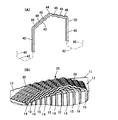
ステータ巻線20の形状について、図1を参照して説明する。
(Shape of stator winding 20)
The shape of the stator winding 20 will be described with reference to FIG.
ステータ巻線20は、ステータコア12のスロット14、15内にそれぞれ収容されるスロット収容部40と、軸方向及び周方向へ延在しつつ周方向略1磁極ピッチ離れた2つのスロット収容部40の端部同士をステータコア12の軸方向両端にて接続するターン部42とを有している。
The stator winding 20 includes a
ターン部42の中央部には、軸方向外側に突出せず周方向へ延在するクランク部(頭頂部)44が形成されている。線材30は、クランク部44にて周方向へ延在するとともに径方向に変位するようにその径方向幅分だけ斜行し、クランク部44の両端はその径方向幅分だけ径方向へずれている。つまり、つまり、クランク部44の一端と他端とは線材30の径方向幅分だけ径方向にずれている。このずれは、クランク部44の一端から他端へ向けて連続的に形成され、クランク部44は周方向へ変位するにつれて径方向へ斜行している。この斜行するクランク部44の周方向幅は略1スロットピッチとされ、スロットの同一径方向位置のスロット収容部に連なる各ターン部のクランク部44は、軸方向等位置に配置される。これにより、互いに隣接する線材30のターン部42を高密度配置することができるため、コイルエンドの膨らみを低減することができる。また、図1(B)に示すように、一つのスロット内のスロット収容部40に連なるターン部42に対してこの一つのスロットの隣のスロット内のスロット収容部40に連なるターン部42は、軸方向に隣接するように配置される。これにより、コイルエンドの膨らみを低減することができる。
A crank portion (head top portion) 44 that extends in the circumferential direction without protruding outward in the axial direction is formed in the central portion of the
スロット収容部40の端部に連なるターン部42の端部には、ステータ11の端面13に沿いつつ周方向(正確には接線方向)へ延在するクランク部46が形成されている。これにより、コイルエンドの高さを低減することができる。つまり、極ピッチよりコイル辺ピッチが短い短節巻と同様の幾何学的効果で全節巻であってもコイルエンド高さを低くできる。更に、ターン部42は、ターン部42の端部と頭頂部との中間に位置して、1スロット間隔で上記クランク部46と同様に周方向へ延在するクランク部48を有する。これにより、コイルエンド高さを更に低くすることができる。
A
図6を参照してこの略階段状のターン部42に効果について更に詳しく説明する。
With reference to FIG. 6, the effect of the substantially step-
図6において、2点鎖線は、スロット14、14間において周方向及び軸方向に延在する従来のターン部330の配置位置を示す。ターン部330はたとえばその中央部にて径方向に捻られ、これによりターン部330の両端は線材の径方向幅だけ径方向にずれている。これに対して、この実施形態のターン部42は、周方向幅d1のクランク部44及びクランク部46、48をもつ分だけ軸方向高さhを縮小することができる。なお、d2はティース12bの周方向幅、42はクランク部44及びクランク部46、48の間にて周方向及び軸方向に延在するターン部42の斜行部である。
In FIG. 6, a two-dot chain line indicates an arrangement position of the
以上説明したように、この実施形態では、矩形断面の導体素線32を積層した線材30を用いているので、スロット占積率を高めることができる。更に、この実施形態では、ステータ巻線20のターン部42にクランク部46、クランク部(頭頂部)44を設け、更に途中のクランク部48を2段設けているので、低くコンパクトなコイルエンドを実現することができる。そのうえ、このターン部42の各クランク部の屈曲加工は、複数の導体素線32を整列させて線材30を構成することにより線材30の変形性を向上しているため容易となっている。更にそのうえ、クランク部44、46、48が屈曲加工して形成された後のターン部42の剛性は増大するため、回転電機の運転等に伴うコイルエンドの振動を良好に抑止することもできる。
As described above, in this embodiment, since the
(ステータ巻線20の製造工程)
上記したステータ巻線20をステータコア12へ巻装する方法の一例について、図2、図3を用いて説明する。図2はステータコア12へのステータ巻線20の組付完了状態を示し、図3は組付け途中状態を示す。ただし、図2、図3の図示を簡略化するため、ステータ巻線20のターン部42の図示は省略され、スロット収容部40の線材30の断面は簡略化して図示されている。
(Manufacturing process of stator winding 20)
An example of a method of winding the above-described stator winding 20 around the
ステータコア12は、電磁鋼板等の軟磁性薄板材を軸方向に積層して構成されている。ステータコア12は、継鉄部(バックヨーク)12aと、継鉄部12aから径方向内側へ突出するティース12bとを有する。隣接する2つのティース12b間には、奇数番目のスロット14と偶数番目のスロット15とが周方向交互に設けられている。19aは、スロット14、15の径方向内側に開口する開口部(スロット開口)であり、スロット14、15の周方向幅は、開口部19aからスロット14、15の奥径部19bに至るまで等しくされている。スロット14、15は、オープンスロット構造となっている。
The
この実施形態の回転電機のステータの製造方法によれば、スロット14、15に径方向へ挿入可能にステータ巻線と同形の整形コイルを予め円筒状に作製しておき、この整形コイルを縮径してステータコア12のロータ配置位置にセットし、その後、この整形コイルの縮径を解除して整形コイルの各スロット収容部40をステータコア12のスロット14、15に収容してステータ巻線20を完成させる。もちろん、上記セットにおいて、各スロット収容部40は、それが収容されるべきスロットの径方向内側に配置される。
According to the method for manufacturing a stator of a rotating electrical machine of this embodiment, a shaping coil having the same shape as the stator winding is prepared in advance in a cylindrical shape so that it can be inserted in the
更に説明すると、図3では、予め円筒状に整形されたステータ巻線20のスロット収容部40の線材30が、ステータコア12の径方向内側に径方向へ12本互いに隣接して配列されている。この状態から、ステータ巻線20のスロット収容部40の線材30を径方向外側へ移動させることにより、ステータ巻線20のスロット収容部40およびそれを囲むスロット絶縁紙80をスロット14、15内に挿入する(図2)。その後、絶縁性樹脂等からなるウェッジ82をスロットの開口部19aに挿入し、ステータ巻線20のスロット収容部40をスロット14、15内に封止する(図2参照)。
More specifically, in FIG. 3, twelve
(第2実施形態)
本発明の第2実施形態を図7に示す。
(Second Embodiment)
A second embodiment of the present invention is shown in FIG.
第2実施形態の線材70には、第1実施形態と同様に捩りを伴わない形状のクランク部76がターン部74の中央部(頭頂部)にほぼ周方向に延在して形成されている。クランク部76では、線材70がその径方向幅分だけ径方向にオフセットして整列されている。つまり、クランク部76の一端と他端とは線材70の径方向幅分だけ径方向にずれている。このずれは、クランク部76の一端から他端へ向けて連続的に形成され、これにより、クランク部76は周方向へ変位するにつれて径方向へ斜行している。この斜行するクランク部76の周方向幅は略1スロットピッチとされ、スロットの同一径方向位置のスロット収容部に連なる各ターン部のクランク部76は、軸方向等位置に配置されることが好適である。これにより、互いに隣接する線材70のターン部74は、密に配置されることができるため、コイルエンドの膨らみを低減することができる。
In the
また、ステータ巻線20には、スロット収容部72に連なるターン部74の端部に位置して、ステータ11の端面13に平行に周方向(正確には接線方向)へ延在するクランク部78が形成されている。これにより、第1実施形態と同様にコイルエンドの高さを低減することができる。ただし、第2実施形態の線材70は、クランク部76とクランク部78との間は直線状に形成され、途中クランク部をもたない。これにより、コイルエンドで線材70の途中クランク部同士が空間的に干渉することを抑止することができる。これにより、径方向内側のスロット収容部72から径方向外側のスロット収容部72に至るターン部74の線材30を径方向に変位させ、組み合わせる作業、並びに、ステータ巻線20のスロット収容部72をスロット14、15内に挿入する作業が容易となる。
Further, the stator winding 20 has a
更に、この実施形態では、絶縁性樹脂層が電着塗装によりスロット内壁に40μm〜80μm厚で形成されている。これにより、図4に示す外層絶縁被膜36の厚さを必要最低限とすることができるため、生産性を損なわずにステータ巻線20のスロット収容部72の占積率を向上できる。
Furthermore, in this embodiment, the insulating resin layer is formed with a thickness of 40 μm to 80 μm on the inner wall of the slot by electrodeposition coating. Thereby, since the thickness of the outer insulating
(第3実施形態)
本発明の第3実施形態を図8、図9に示す。
(Third embodiment)
A third embodiment of the present invention is shown in FIGS.
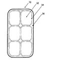
図9に示すようにステータ巻線20の線材70は、銅を素材とする6本の長方形断面形状の導体素線32を含む。導体素線32の外周は内層絶縁被膜34にて覆われ、その外周を外層絶縁被膜36により覆われ、これにより線材70は実質的に単一の線材とされている。6本の導体素線32は長方形断面の長辺同士が接する向きに2列、短辺同士が接する向きに3列に積層されている。長辺は径方向へ、短辺は周方向へ延在している。
As shown in FIG. 9, the
内層絶縁被膜34はポリアミドイミド等のエナメル層により形成され、外層絶縁被膜36はPPS等の押出し被覆樹脂層により形成されている。内層絶縁被膜34と外層絶縁被膜36とを合わせた絶縁被膜の厚さは100μm〜170μmに設定され、この絶縁被膜のみでサージ電圧による部分放電(コロナ放電)を防止している。
The inner insulating
図8において、ステータコア12は、電磁鋼板等の軟磁性薄板材からなり、継鉄部12aと、この継鉄部12aから内径側に突出したティース12bを形成している。このティース12b間には側壁が平行なスロット14、15が設けられ、オープンスロット構造が採用されている。
In FIG. 8, the
ステータ巻線20の各スロット収容部72の線材70はすべて、収容されるべきスロットの径方向内側に予め配置される。これにより、各スロットの径方向内側には6本のスロット収容部72が径方向へ整列して予め配置される。その後、スロット収容部72の線材70を径方向外側へ移動させることにより、各スロット収容部72が、スロット14、15内に挿入される。
All the
この第3実施形態によれば、図9に示す線材70の素線数を図4に示す場合より径方向へ増やしているため、線材70の電流容量を増やすことができるうえに、図4に示す場合に比べてターン部の線材70を容易に周方向へ曲げることができる。つまり、一本の平角線からなる線材では製作困難な総断面積の線材70も容易に加工することができ、大電流にも対応できる。また、この実施形態では、毎極毎相2スロットを配置しているため毎極毎相1スロット構成の場合と比較して線材70の整形工程及び既述の縮径工程を容易とすることができる。
According to the third embodiment, since the number of strands of the
(他の実施形態)
上記実施形態では、ステータ巻線20の線材30(70)は、導体素線32は長方形断面の長辺同士が接する向きかつ周方向へ複数列(2列)、短辺同士が接する向きかつ径方向へ複数列(2列または3列)、配列していた。しかし、電流容量が小さい場合には図10、図11に示すように、周方向及び径方向の一方へのみ複数列配列し、周方向及び径方向の他方へは単列だけ配列してもよい。図10では、スロット内に収容された状態において、導体素線は径方向へ単列だけ配置され、周方向へ2列に積層(配列)され、且つ、積層方向(周方向)に偏平な断面形状を有する。つまり、短辺が周方向へ長辺が径方向へ配置される。このようにすれば、厚被膜積層線(線材)の周方向への曲げ剛性を低下することができるのでターン部を周方向に撓ませることが容易になり、ステータ巻線のスロット収容部をステータコアの径方向内側からスロット位置まで移動させる挿入工程も容易となる。
(Other embodiments)
In the above embodiment, the wire 30 (70) of the stator winding 20 has the
図11では、スロット内に収容された状態において、導体素線32は周方向に単列、径方向に2列に2列に積層され、且つ、積層方向に偏平な断面形状を有する。つまり、短辺が径方向へ長辺が周方向へ配置される。このため、厚被膜積層線の径方向の曲げ剛性を低下することができるので、厚被膜積層線の径方向寸法を大きくしてもターン部を径方向に撓ませることが容易となり、厚被膜積層線の径方向寸法を増やすことで大電流仕様に対応できる。
In FIG. 11, the
また、上記実施形態では、ステータ巻線20の線材30(70)は、矩形断面形状の導体素線32の外周をガラス転移温度が相対的に高い熱可塑性樹脂(たとえばポリアミドイミド)からなる内層絶縁被膜34により被覆し、その外周をガラス転移温度が相対的に低い熱可塑性樹脂(たとえばナイロン等)からなる外層絶縁被膜36により被覆している。これにより、高温時、内層より先に外層絶縁被膜が軟化し同一スロット内の線材どうしが熱接着し径方向に整列して一体化することで、ステータ巻線の機械強度を向上することができる。また、過大な振動等が加わっても内層と外層の接着箇所が先に剥離するので内層絶縁被膜と導体の接着を維持し絶縁性を確保できる。
Further, in the above embodiment, the wire 30 (70) of the stator winding 20 has an inner layer insulation made of a thermoplastic resin (for example, polyamideimide) having a relatively high glass transition temperature around the outer periphery of the
上記実施形態ではステータ巻線20の線材30(70)の素線として、矩形断面形状導体(平角線)を用いたが、入手容易な円形断面形状の丸線を用い、スロット収容部40(72)のみを押圧加工して偏平断面形状としてもよい。このようにすると、ターン部42の曲げ加工が容易となる。
In the above embodiment, a rectangular cross-section conductor (flat wire) is used as the wire of the wire 30 (70) of the stator winding 20, but a round cross-section round wire that is easily available is used, and the slot accommodating portion 40 (72 ) May be pressed into a flat cross-sectional shape. If it does in this way, the bending process of the
なお、本発明は、上記実施形態に限定されるものではなく、その要旨を逸脱しない範囲で種々の実施形態に適用可能である。 In addition, this invention is not limited to the said embodiment, In the range which does not deviate from the summary, it is applicable to various embodiment.
11 ステータ
12 ステータコア
12a 継鉄部
12b ティース
13 ステータの端面
14 スロット
15 スロット
19a 開口部
19b 奥径部
20 ステータ巻線
30 線材(厚被膜積層線)
32 導体素線
34 内層絶縁被膜(絶縁被膜)
36 外層絶縁被膜(樹脂被覆部)
40 スロット収容部
42 ターン部
44 クランク部
46 クランク部
48 クランク部
70 線材
72 スロット収容部
74 ターン部
76 クランク部
78 クランク部
80 スロット絶縁紙
82 ウェッジ
DESCRIPTION OF
32
36 Outer insulation coating (resin coating)
40
Claims (10)
前記ステータ巻線は、周方向略磁極ピッチ離れた2つの前記スロットに個別に収容される1対のスロット収容部と、前記ステータコアの軸方向外側にて前記1対のスロット収容部を接続するターン部とを有し、
前記ステータ巻線は、互いに面接触状態にて積層され且つそれぞれ樹脂被膜により絶縁被覆されて互いに平行に延在する複数の導体素線と、前記複数の導体素線を囲包する樹脂被覆部とを有する厚被膜積層線により構成されており、
前記ターン部の端部は、前記スロットの端部に位置する前記スロット収容部の端部から前記ティースの端面に沿いつつ周方向へ延在するクランク部を有し、
前記ターン部は、周方向へ延在するとともに前記厚被膜積層線1本分に略等しい幅だけ径方向へ斜行する頭頂部を有していることを特徴とする回転電機のステータ。 In a stator of a rotating electrical machine comprising a cylindrical stator core in which slots and teeth are alternately formed in the circumferential direction, and a stator winding housed in the slot,
The stator winding is a turn that connects a pair of slot accommodating portions individually accommodated in two slots spaced apart from each other by a substantially magnetic pole pitch in the circumferential direction, and the pair of slot accommodating portions outside in the axial direction of the stator core. And
The stator winding includes a plurality of conductor strands laminated in a surface contact state with each other and insulated and coated with a resin coating, respectively, and a resin coating portion surrounding the plurality of conductor strands. is constituted by a thick film multilayer line having,
The end of the turn portion has a crank portion extending in the circumferential direction along the end surface of the teeth from the end of the slot accommodating portion located at the end of the slot,
The stator of a rotating electrical machine, wherein the turn part has a top part extending in a circumferential direction and obliquely inclined in a radial direction by a width substantially equal to one thick film laminated line .
前記複数の導体素線は、前記スロット内にて少なくとも周方向へ積層され且つ短辺が周方向へ延在する長方形断面形状を有する回転電機のステータ。 The stator of the rotating electrical machine according to claim 1 ,
The stator of a rotating electrical machine, wherein the plurality of conductor strands have a rectangular cross-sectional shape in which at least a circumferential direction is laminated in the slot and a short side extends in the circumferential direction.
前記複数の導体素線は、前記スロット内にて少なくとも径方向へ積層され且つ短辺が径方向へ延在する長方形断面形状を有する回転電機のステータ。 The stator of the rotating electrical machine according to claim 1 ,
The plurality of conductor wires are stators of a rotating electrical machine having a rectangular cross-sectional shape in which at least a radial direction is laminated in the slot and a short side extends in the radial direction.
前記複数の導体素線は、前記スロット内にて略周方向及び略径方向へ延在する側面を有して径方向及び周方向の両方へ整列して積層された平角線によりそれぞれ構成されている回転電機のステータ。 The stator of the rotating electrical machine according to claim 1 ,
The plurality of conductor wires are respectively configured by rectangular wires that have side surfaces extending in a substantially circumferential direction and a substantially radial direction in the slot and are stacked in alignment in both the radial direction and the circumferential direction. The stator of the rotating electrical machine.
前記樹脂被膜は、100〜170μmの厚さを有する回転電機のステータ。 The stator of the rotating electrical machine according to any one of claims 1 to 4 ,
The resin film is a stator of a rotating electric machine having a thickness of 100 to 170 μm.
前記樹脂被覆部は、押出し成形により形成されている回転電機のステータ。 In the stator of the rotating electrical machine according to any one of claims 1 to 5 ,
The resin coating portion is a stator of a rotating electric machine formed by extrusion molding.
前記樹脂被膜は、内側に形成されて前記樹脂被膜をなす内層絶縁被膜と、前記内層絶縁被膜を被覆して前記樹脂被覆部をなす外層絶縁被膜とからなり、前記外層絶縁被膜は、前記内層絶縁被膜よりも低いガラス転移温度を有する回転電機のステータ。 In the stator of the rotary electric machine according to any one of claims 1 to 6 ,
The resin coating includes an inner layer insulating coating formed on the inner side to form the resin coating, and an outer layer insulating coating that covers the inner layer insulating coating to form the resin coating portion, and the outer layer insulating coating is formed of the inner layer insulating coating. A stator for a rotating electrical machine having a glass transition temperature lower than that of a coating.
前記スロットの内壁面は、絶縁性樹脂層により被覆されている回転電機のステータ。 In the stator of the rotating electrical machine according to any one of claims 1 to 7 ,
A stator of a rotating electrical machine in which an inner wall surface of the slot is covered with an insulating resin layer.
前記絶縁性樹脂層は、電着塗装により形成されている回転電機のステータ。 The stator of the rotating electrical machine according to claim 8 ,
The insulating resin layer is a stator of a rotating electric machine formed by electrodeposition coating.
Priority Applications (1)
| Application Number | Priority Date | Filing Date | Title |
|---|---|---|---|
| JP2007169325A JP4919059B2 (en) | 2007-06-27 | 2007-06-27 | Stator for rotating electrical machine and method for manufacturing the same |
Applications Claiming Priority (1)
| Application Number | Priority Date | Filing Date | Title |
|---|---|---|---|
| JP2007169325A JP4919059B2 (en) | 2007-06-27 | 2007-06-27 | Stator for rotating electrical machine and method for manufacturing the same |
Publications (2)
| Publication Number | Publication Date |
|---|---|
| JP2009011064A JP2009011064A (en) | 2009-01-15 |
| JP4919059B2 true JP4919059B2 (en) | 2012-04-18 |
Family
ID=40325572
Family Applications (1)
| Application Number | Title | Priority Date | Filing Date |
|---|---|---|---|
| JP2007169325A Active JP4919059B2 (en) | 2007-06-27 | 2007-06-27 | Stator for rotating electrical machine and method for manufacturing the same |
Country Status (1)
| Country | Link |
|---|---|
| JP (1) | JP4919059B2 (en) |
Cited By (1)
| Publication number | Priority date | Publication date | Assignee | Title |
|---|---|---|---|---|
| US12046969B2 (en) | 2020-03-11 | 2024-07-23 | Kabushiki Kaisha Toshiba | Stator of rotary electric machine and rotary electric machine |
Families Citing this family (12)
| Publication number | Priority date | Publication date | Assignee | Title |
|---|---|---|---|---|
| JP5352979B2 (en) * | 2007-09-20 | 2013-11-27 | 株式会社デンソー | Stator for rotating electric machine and method for manufacturing the same |
| JP5093582B2 (en) * | 2007-10-10 | 2012-12-12 | 株式会社デンソー | Segment type stator, rotating electric machine and driving device |
| JP2010259316A (en) * | 2009-03-31 | 2010-11-11 | Denso Corp | Stator for rotary electric machine and manufacturing method of the same |
| JP5445033B2 (en) * | 2009-10-28 | 2014-03-19 | 株式会社デンソー | Rotating electric machine stator |
| DE112011100077T5 (en) * | 2010-02-18 | 2012-10-31 | Aisin Aw Co., Ltd. | Anchor for a rotating electrical machine |
| JP2011223652A (en) * | 2010-04-05 | 2011-11-04 | Toyota Central R&D Labs Inc | Rotating electric machine winding and rotating electric machine component member |
| JP6048191B2 (en) * | 2013-02-12 | 2016-12-21 | 株式会社デンソー | Multi-gap rotating electric machine |
| KR102438991B1 (en) | 2017-11-28 | 2022-09-02 | 삼성전자주식회사 | Memory device and operation method thereof |
| JP2020025418A (en) * | 2018-08-08 | 2020-02-13 | 日立オートモティブシステムズ株式会社 | Stator of rotary electric machine and rotary electric machine having the same |
| EP4117149A4 (en) * | 2020-03-05 | 2023-11-29 | Kabushiki Kaisha Toshiba | Stator for dynamo-electric machine, and dynamo-electric machine |
| CN114157071A (en) * | 2021-12-06 | 2022-03-08 | 广东汇天航空航天科技有限公司 | Stator, stator manufacturing method, and rotating electrical machine |
| CN116404789B (en) * | 2023-06-09 | 2023-09-22 | 中国第一汽车股份有限公司 | Motor and driving system with same and vehicle |
Family Cites Families (8)
| Publication number | Priority date | Publication date | Assignee | Title |
|---|---|---|---|---|
| JPS57129141A (en) * | 1981-02-03 | 1982-08-11 | Kazuo Sano | Single layer half-wound coil |
| JP3134304B2 (en) * | 1990-10-31 | 2001-02-13 | 日本電産株式会社 | motor |
| JP2001309619A (en) * | 2000-04-25 | 2001-11-02 | Mitsuba Corp | Winding method for stator coil in rotating electric machine |
| JP2002044892A (en) * | 2000-07-27 | 2002-02-08 | Matsushita Electric Ind Co Ltd | Electric motor and electric compressor mounted with this electric motor |
| JP2003086026A (en) * | 2001-09-13 | 2003-03-20 | Totoku Electric Co Ltd | Laminated flat enameled electric wire for high frequency electricity and method for manufacturing the same |
| JP2003158840A (en) * | 2001-11-16 | 2003-05-30 | Toyota Motor Corp | Stator for rotating electric machine for vehicle |
| JP2004064989A (en) * | 2002-06-04 | 2004-02-26 | Toyota Motor Corp | Stator for segment coil rotary electric machine and its manufacturing method |
| JP2006158024A (en) * | 2004-11-26 | 2006-06-15 | Sumitomo Electric Ind Ltd | Coil and its manufacturing method |
-
2007
- 2007-06-27 JP JP2007169325A patent/JP4919059B2/en active Active
Cited By (1)
| Publication number | Priority date | Publication date | Assignee | Title |
|---|---|---|---|---|
| US12046969B2 (en) | 2020-03-11 | 2024-07-23 | Kabushiki Kaisha Toshiba | Stator of rotary electric machine and rotary electric machine |
Also Published As
| Publication number | Publication date |
|---|---|
| JP2009011064A (en) | 2009-01-15 |
Similar Documents
| Publication | Publication Date | Title |
|---|---|---|
| JP4919059B2 (en) | Stator for rotating electrical machine and method for manufacturing the same | |
| US10461591B2 (en) | Rotary electric machine with armature coil end top portions displaced in a radial direction | |
| JP5532319B2 (en) | Stator for rotating electric machine and method for manufacturing the same | |
| JP4624421B2 (en) | Permanent magnet synchronous machine with rectangular wire winding | |
| US9172280B2 (en) | Conductor and rotating electrical machine with a covering material | |
| JP4577588B2 (en) | Method for manufacturing coil assembly of rotating electrical machine | |
| JP5126577B2 (en) | Rotating electric machine stator | |
| JP6165260B2 (en) | Rotating electric machine | |
| US7239059B2 (en) | Stator of rotating electric machine and manufacturing method of the stator | |
| JP5848579B2 (en) | Segment coil, segment coil manufacturing method, and stator | |
| JP5774082B2 (en) | Rotating electric machine | |
| US20100148620A1 (en) | Stator for electric rotating machine | |
| JP2010011715A (en) | Coil wire for coil assembly for rotating electrical machine | |
| JP2008245489A (en) | Stator for electrical rotating machine | |
| JP3903609B2 (en) | Wave winding coil of rotating electric machine and method for manufacturing the same | |
| JP6598736B2 (en) | Rotating electric machine stator | |
| JP5163278B2 (en) | Rotating electric machine stator | |
| JP2007336725A (en) | Stator of rotating electric machine | |
| JP4535147B2 (en) | Rotating electric machine stator and rotating electric machine | |
| JP5072502B2 (en) | Rotating motor | |
| JP2006067756A (en) | Stator for rotary electric machine, and manufacturing method for stator for the rotary electric machine | |
| JP5152578B2 (en) | Method for manufacturing coil assembly of rotating electrical machine | |
| JP7210128B2 (en) | Rotating electric machine, method for manufacturing tortoiseshell-shaped coil, and manufacturing apparatus for tortoiseshell-shaped coil | |
| JP6000051B2 (en) | Electric machine and manufacturing method thereof | |
| JP3771875B2 (en) | Rotating electric machine stator |
Legal Events
| Date | Code | Title | Description |
|---|---|---|---|
| A621 | Written request for application examination |
Free format text: JAPANESE INTERMEDIATE CODE: A621 Effective date: 20091019 |
|
| A977 | Report on retrieval |
Free format text: JAPANESE INTERMEDIATE CODE: A971007 Effective date: 20110906 |
|
| A131 | Notification of reasons for refusal |
Free format text: JAPANESE INTERMEDIATE CODE: A131 Effective date: 20110913 |
|
| A521 | Request for written amendment filed |
Free format text: JAPANESE INTERMEDIATE CODE: A523 Effective date: 20111114 |
|
| TRDD | Decision of grant or rejection written | ||
| A01 | Written decision to grant a patent or to grant a registration (utility model) |
Free format text: JAPANESE INTERMEDIATE CODE: A01 Effective date: 20120105 |
|
| A01 | Written decision to grant a patent or to grant a registration (utility model) |
Free format text: JAPANESE INTERMEDIATE CODE: A01 |
|
| A61 | First payment of annual fees (during grant procedure) |
Free format text: JAPANESE INTERMEDIATE CODE: A61 Effective date: 20120118 |
|
| R151 | Written notification of patent or utility model registration |
Ref document number: 4919059 Country of ref document: JP Free format text: JAPANESE INTERMEDIATE CODE: R151 |
|
| FPAY | Renewal fee payment (event date is renewal date of database) |
Free format text: PAYMENT UNTIL: 20150210 Year of fee payment: 3 |
|
| R250 | Receipt of annual fees |
Free format text: JAPANESE INTERMEDIATE CODE: R250 |
|
| R250 | Receipt of annual fees |
Free format text: JAPANESE INTERMEDIATE CODE: R250 |
|
| R250 | Receipt of annual fees |
Free format text: JAPANESE INTERMEDIATE CODE: R250 |
|
| R250 | Receipt of annual fees |
Free format text: JAPANESE INTERMEDIATE CODE: R250 |
|
| R250 | Receipt of annual fees |
Free format text: JAPANESE INTERMEDIATE CODE: R250 |
|
| R250 | Receipt of annual fees |
Free format text: JAPANESE INTERMEDIATE CODE: R250 |
|
| R250 | Receipt of annual fees |
Free format text: JAPANESE INTERMEDIATE CODE: R250 |
|
| R250 | Receipt of annual fees |
Free format text: JAPANESE INTERMEDIATE CODE: R250 |
|
| R250 | Receipt of annual fees |
Free format text: JAPANESE INTERMEDIATE CODE: R250 |