JP4535147B2 - Rotating electric machine stator and rotating electric machine - Google Patents
Rotating electric machine stator and rotating electric machine Download PDFInfo
- Publication number
- JP4535147B2 JP4535147B2 JP2008049922A JP2008049922A JP4535147B2 JP 4535147 B2 JP4535147 B2 JP 4535147B2 JP 2008049922 A JP2008049922 A JP 2008049922A JP 2008049922 A JP2008049922 A JP 2008049922A JP 4535147 B2 JP4535147 B2 JP 4535147B2
- Authority
- JP
- Japan
- Prior art keywords
- coil
- fixing member
- stator
- stator core
- winding
- Prior art date
- Legal status (The legal status is an assumption and is not a legal conclusion. Google has not performed a legal analysis and makes no representation as to the accuracy of the status listed.)
- Expired - Fee Related
Links
Images


Classifications
-
- H—ELECTRICITY
- H02—GENERATION; CONVERSION OR DISTRIBUTION OF ELECTRIC POWER
- H02K—DYNAMO-ELECTRIC MACHINES
- H02K3/00—Details of windings
- H02K3/46—Fastening of windings on the stator or rotor structure
- H02K3/48—Fastening of windings on the stator or rotor structure in slots
-
- H—ELECTRICITY
- H02—GENERATION; CONVERSION OR DISTRIBUTION OF ELECTRIC POWER
- H02K—DYNAMO-ELECTRIC MACHINES
- H02K3/00—Details of windings
- H02K3/32—Windings characterised by the shape, form or construction of the insulation
- H02K3/38—Windings characterised by the shape, form or construction of the insulation around winding heads, equalising connectors, or connections thereto
-
- H—ELECTRICITY
- H02—GENERATION; CONVERSION OR DISTRIBUTION OF ELECTRIC POWER
- H02K—DYNAMO-ELECTRIC MACHINES
- H02K3/00—Details of windings
- H02K3/46—Fastening of windings on the stator or rotor structure
- H02K3/50—Fastening of winding heads, equalising connectors, or connections thereto
Description
本発明は、固定子コアとコイルとの位置のズレを規制するコイルの固定部材を有する回転電機の固定子及び回転電機に関する。 The present invention relates to a stator of a rotating electrical machine having a coil fixing member that restricts a positional deviation between a stator core and a coil, and the rotating electrical machine.
近年、電動機および発電機として使用される回転電機において、小型高出力および品質の向上が求められている。 In recent years, rotating electric machines used as electric motors and generators have been required to be small and have high output and improved quality.
例えば、車両に搭載される回転電機においては、車両のエンジンルームで回転電機を搭載するためのスペースが小さくなってきている一方で、車両負荷の増大による発電出力の向上が求められている。また、信頼性の向上も求められている。 For example, in a rotating electrical machine mounted on a vehicle, a space for mounting the rotating electrical machine in an engine room of the vehicle is becoming smaller, and an improvement in power generation output due to an increase in vehicle load is required. There is also a need for improved reliability.
特許文献1および2には、固定子コアとコイルとの間に絶縁スペーサを設置している回転電機が開示されている。
しかしながら、これらの回転電機においては、絶縁スペーサが固定子コアおよびコイルの間に挿入してあるのみであり、両者のいずれにも支持されていない。このため、回転電機の使用時に振動や熱・機械ストレス等により絶縁スペーサがズレたり脱落する可能性がある。絶縁スペーサが脱落すると、コイルと固定子コアとの接触が起こりコイルを構成する固定子巻線の絶縁性能の低下や振動等のストレスが加わることにより巻線が損傷し、回転電機の信頼性が低下するおそれがある。
本発明は上記実状に鑑みてなされたものであり、回転電機のコイルと固定子コアとの間に介在するとともに脱落が抑えられたコイルの固定部材を有する回転電機の固定子および回転電機を提供することを課題とする。 The present invention has been made in view of the above circumstances, and provides a stator of a rotating electrical machine and a rotating electrical machine having a coil fixing member that is interposed between the coil of the rotating electrical machine and a stator core and suppressed from falling off. The task is to do.
上記課題を解決するために本発明者らは検討を重ねた結果、コイルの固定部材が、径方向の外方と内方の両方から挿入される二つの部材の組み合わせよりなる構成とすることで上記課題を解決できることを見出した。 As a result of repeated studies by the present inventors to solve the above-mentioned problems, the coil fixing member is constituted by a combination of two members inserted from both the radially outer side and the inner side. It has been found that the above problems can be solved.
すなわち、請求項1に記載の本発明の回転電機の固定子は、スロットを周方向に複数有する固定子コアと、周方向の異なるスロットに収容されるスロット収容部と、スロットの外部でスロット収容部同士を接続している接続部と、を有する固定子巻線により形成されるコイルと、を備えた回転電機の固定子において、固定子コアの少なくとも一方の端面とコイルの接続部との間に介在してコイルと固定子コアの変移を規制するコイルの固定部材を備え、固定部材は、接続部と固定子コアの端面との間に径方向の外方から挿入され、該接続部を構成する巻線に一致する凹凸形状に形成されて該接続部を保持する保持部が周方向の一方側に形成されたくさび状の第一固定部材と、接続部と固定子コアの端面との間であって第一固定部材の周方向の他方側に径方向内方から挿入される棒状の第二固定部材と、を有することを特徴とする。 That is, the stator of the rotating electrical machine according to the first aspect of the present invention includes a stator core having a plurality of slots in the circumferential direction, a slot accommodating portion accommodated in a different slot in the circumferential direction, and a slot accommodating outside the slot. In a stator of a rotating electrical machine comprising a coil formed by a stator winding having a connection part that connects parts to each other, between at least one end face of the stator core and the connection part of the coil interposed comprise a stationary member of the coil to regulate the displacement of the coil and the stator core, the fixing member is inserted from the outside in the radial direction between the end face of the connecting portion and the stator core, the connecting portion A wedge-shaped first fixing member that is formed in a concave-convex shape that coincides with the windings that are formed and has a holding portion that holds the connection portion formed on one side in the circumferential direction, and a connection portion and an end surface of the stator core In the circumferential direction of the first fixing member And a second fixing rod-like member which is inserted in a square side from radially inwardly to have a characterized.
請求項2に記載の本発明の回転電機の固定子は、請求項1において、第二固定部材は、コイルの径方向の最外周面に係止する係止部を有することを特徴とする。 According to a second aspect of the present invention, the stator of the rotating electrical machine according to the first aspect of the present invention is characterized in that the second fixing member has a locking portion that is locked to the outermost peripheral surface in the radial direction of the coil.
請求項3に記載の本発明の回転電機の固定子は、請求項1〜2のいずれかにおいて、第一固定部材は、第二固定部材の径方向外方に、第二固定部材が径方向外方に変移することを規制する規制部を有することを特徴とする。 A stator for a rotating electrical machine according to a third aspect of the present invention is the stator according to any one of the first to second aspects, wherein the first fixing member is radially outward of the second fixing member, and the second fixing member is radial. It has the control part which controls shifting to the outside.
また、請求項4に記載の本発明の回転電機は、請求項1〜3のいずれかに記載の固定子を用いてなることを特徴とする。 A rotating electric machine according to a fourth aspect of the present invention is characterized by using the stator according to any one of the first to third aspects.
請求項1に記載の本発明の回転電機の固定子は、コイルの固定部材が、径方向の反対側から組み付けられる第一及び第二固定部材から構成される。これにより、第一及び第二固定部材のそれぞれのズレが抑えられ、コイルの固定部材がコイルと固定子コアの変移を規制する。この結果、本発明の回転電機の固定子を用いた回転電機に振動や熱・機械ストレス等が付与されても、固定部材が脱落しなくなった。この結果、回転電機の性能の低下が抑えられる。 The stator of the rotating electrical machine of the first aspect of the present invention, the fixing member of the coil, and a first and second fixing member is assembled from the opposite side in the radial direction. Thereby, each shift | offset | difference of a 1st and 2nd fixing member is suppressed, and the fixing member of a coil controls the transition of a coil and a stator core. As a result, even when vibration, heat, mechanical stress, or the like is applied to the rotating electrical machine using the rotating electrical machine stator of the present invention, the fixing member does not fall off. As a result, a decrease in performance of the rotating electrical machine can be suppressed.
請求項2に記載の本発明の回転電機の固定子は、第二固定部材がコイルに係止されることで、第二固定部材が径方向にずれることが抑えられる。 In the stator of the rotating electrical machine according to the second aspect of the present invention, the second fixing member is restrained from shifting in the radial direction by the second fixing member being locked to the coil.
請求項3に記載の本発明の回転電機の固定子は、第一固定部材が規制部を有することで第二固定部材が径方向外方にずれることが抑えられる。 In the stator of the rotating electrical machine according to the third aspect of the present invention, the second fixing member can be prevented from shifting outward in the radial direction because the first fixing member has the restricting portion.
また、請求項4に記載の本発明の回転電機は、上記の各固定子を有する。各固定子は、回転電機に振動や熱・機械ストレス等が付与されても、固定部材が脱落しなくなっている。すなわち、本発明の回転電機は、固定部材の脱落による性能の低下が抑えられた回転電機となっている。 According to a fourth aspect of the present invention, there is provided a rotating electrical machine according to the present invention having the above-described stators . In each stator , even if vibration, heat, mechanical stress, or the like is applied to the rotating electrical machine, the fixing member does not fall off. In other words, the rotating electrical machine of the present invention is a rotating electrical machine in which a decrease in performance due to the dropping of the fixing member is suppressed.
以下、実施の形態を用いて本発明を具体的に説明する。 Hereinafter, the present invention will be specifically described with reference to embodiments.
(実施形態例)
本実施形態のコイルの固定部材は、コイル4と固定子コア30とを備えた固定子3と回転子2とを備えた回転電機1に用いられる。
(Example embodiment)
The coil fixing member of this embodiment is used in a rotating electrical machine 1 including a stator 3 including a coil 4 and a
本実施形態のコイルの固定部材5の構成を図1〜3に示す。コイルの固定部材5は、第一固定部材51と、第二固定部材52と、から構成される。
The structure of the
第一固定部材51及び第二固定部材52は、コイル4と固定子コア30との間に介在する状態で、固定子コア30に対して背向した表面の角部がなめらかなR形状をなすテーパ状に形成されている。
The
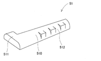
第一固定部材51は、図2に示したように、略くさび板状の本体部510と、本体部510の径方向外方側の端部でありかつ略くさび状の広がった端部側に一体に形成された規制部511と、を有している。規制部511は、本体部510の幅方向の一方側に突出している。
As shown in FIG. 2, the
本体部510の幅方向の他方側の側面には、コイル4の接続部45を構成する巻線40を保持する保持部512が形成されている。保持部512は、接続部45を構成する巻線40に略一致する凹凸形状に形成された本体部510の表面よりなる。
On the other side surface of the
第二固定部材52は、図3に示したように、基端部520、薄肉部521及びツメ部522を有する略棒状の部材である。
As shown in FIG. 3, the
基端部520は、コイル4と固定子コア30との間に介在する状態で、径方向内方側に位置する断面略扇状の部材である。
The
薄肉部521は、基端部520に一体に形成され、基端部520から径方向外方に伸びる略板状の部材である。薄肉部521は、固定子コア30の端面との間にすき間を有する状態で設けられている。
The
ツメ部522は、薄肉部521の先端部に、固定子コア30から離反する方向に突出している。ツメ部522は、第二固定部材52がコイル4と固定子コア30との間に介在する状態で、コイル4の接続部45に当接可能な位置にもうけられている。そして、コイル4の接続部45にツメ部552が係止され、第二固定部材52が径方向内方に抜けることが防止される。
The nail |
本実施形態の固定部材5の組付けは、図4に示したように、コイル4の接続部45と固定子コア30の端面との間にギャップを有する固定子に用いられる。
As shown in FIG. 4, the assembly of the
まず、第一固定部材51を径方向外方から内方にむかって、コイル4の接続部45と固定子コア30の端面との間のギャップに挿入する。このとき、接続部45が接続する一対のスロット31の間の略中央部で挿入する。
First, the
そして、第一固定部材51の径方向位置が所定の位置となったら、本体部510の幅方向の他方側に変移させ、保持部512をコイル4の接続部45に嵌合させる。保持部512が接続部45に嵌合したことで、図5に示したように、第一固定部材51がギャップ内で固定される。このとき、本体部510が接続部45を構成する巻線40のうち、保持部512と当接する巻線40の軸方向での変移が規制される。
And if the radial direction position of the
その後、第二固定部材55を径方向内方から外方にむかって、コイル4の接続部45と固定子コア30の端面との間のギャップであり、かつ第一固定部材51の本体部510の一方の側方のギャップに挿入する。挿入時には、薄肉部521自身の弾性により薄肉部521の先端部が固定子コア30方向に湾曲し、ツメ部522が押し下げられて接続部45と干渉しなくなっている。
Thereafter, the second fixing member 55 is directed from the inside in the radial direction to the outside, the gap between the
そして、第二固定部材52が挿入されて、ツメ部522の径方向位置がコイル4の径方向での外周面の外方に到達すると、薄肉部521が湾曲形状から板状に形状が復元する。これにより、ツメ部522の軸方向での位置が接続部45の軸方向での位置と重なり合い、係止される。このとき、ツメ部522の側面が接続部45の外周面と当接する。この結果、第二固定部材52が径方向内方にズレを生じようとしても、ツメ部522がコイル4に係止されており、ズレが生じない。
And if the
また、挿入された第二固定部材52の径方向外方には、第一固定部材51の規制部511が位置しており、第二固定部材52が径方向外方に移動することを規制している。
Further, a restricting
さらに、図6に示したように、第一固定部材51の本体部510と第二固定部材52の基端部520とで、コイルの径方向の厚さの内周側で、接続部45の巻線40の周方向での変移が規制されている。
Further, as shown in FIG. 6, the
この結果、本実施形態の固定部材5は、固定子コア30の端面とコイル4の接続部45との間のギャップを打ち消すことができ、固定子コア30とコイル4とが固定される。
As a result, the fixing
本実施形態の固定部材5が組み付けられる回転電機1について説明する。
The rotating electrical machine 1 to which the fixing
本実施形態の回転電機の構成を図7に示した。本実施形態の回転電機1は、略有底筒状の一対のハウジング部材100,101とが開口部同士で接合されてなるハウジング10と、ハウジング10に軸受け110,111を介して回転自在に支承される回転軸20に固定された回転子2と、ハウジング10の内部で回転子2を包囲する位置でハウジング10に固定された固定子3と、を備えている。
The configuration of the rotating electrical machine of this embodiment is shown in FIG. The rotating electrical machine 1 according to the present embodiment includes a
回転子2は、永久磁石により周方向に交互に異なる磁極を、固定子3の内周側と向き合う外周側に複数形成している。回転子2の磁極の数は、回転電機により異なるため限定されるものではない。本実施形態においては、8極(N極:4、S極:4)の回転子が用いられている。
The
固定子3は、固定子コア30と、複数の各相巻線から形成される三相のコイル4と、固定子コア30とコイル4との間に配された絶縁紙(図示せず)と、を備えた構成を有している。
The stator 3 includes a
固定子コア30は、内周に複数のスロット31が形成された円環状を有している。複数のスロット31は、その深さ方向が径方向と一致するように形成されている。固定子コア30に形成されたスロット31の数は、回転子2の磁極数に対し、コイル4の一相あたり2個の割合で形成されている。すなわち、8×3×2=48個のスロット31が形成されている。
The
固定子コア30は、所定の数の分割コアを周方向に配設して形成されている。本実施形態においては、24個である。分割コアは、ひとつのスロット31を区画するとともに、周方向で隣接する分割コアとの間でひとつのスロットを区画する形状(径方向内方に伸びるティース部と、ティース部が形成されるバックコア部)に形成されている。
The
固定子コア30(を構成する分割コア)は、0.3mmの厚さの電磁鋼板410枚を積層させて形成されている。なお、積層された電磁鋼板の間には、絶縁薄膜が配置されている。なお、固定子コア30は、この電磁鋼板の積層体からだけでなく、従来公知の金属薄板および絶縁薄膜を用いて形成してもよい。
The stator core 30 (a divided core constituting the stator core 30) is formed by laminating 410 electromagnetic steel sheets having a thickness of 0.3 mm. An insulating thin film is disposed between the laminated electrical steel sheets. The
コイル4は、複数の巻線40を所定の巻回方法で巻回してなる。コイル4を構成する巻線40は、図8(A)に示したように、銅製の導体41と、導体41の外周を覆い導体41を絶縁する内層420及び外層421からなる絶縁皮膜42とから形成されている。内層420および外層421を合わせた絶縁皮膜42の厚みは、100μm〜200μmの間に設定されている。このように、内層420および外層421からなる絶縁皮膜42の厚みが厚いので、巻線40同士を絶縁するために巻線40同士の間に絶縁紙等を挟み込んで絶縁する必要がなくなっているが、線材同士を絶縁するためにあるいは固定子コア30との間に絶縁紙を配してもよい。
The coil 4 is formed by winding a plurality of
外層421はナイロン等の絶縁材、内層420は外層よりもガラス転移温度の高い熱可塑性樹脂またはポリアミドイミド等の絶縁材で形成されている。これにより、回転電機に発生する熱により外層421は内層420よりも早く軟化するので、同じスロット31に設置されている巻線40同士が外層421同士で熱接着する。その結果、同じスロット31に設置されている複数の巻線40が一体化し巻線40同士が剛体化するので、スロット31内の線巻線40の機械的強度が向上する。また、過剰な振動が発生しても、内層420と導体41の接着箇所よりも内層420と外層421との接着箇所が先に剥離するので、内層420と導体41との接着を維持し絶縁を確保できる。
The
さらに、コイル4の巻線40は、図8(B)に示したように、内層420および外層421からなる絶縁皮膜42の外周をエポキシ樹脂等からなる融着材48で被覆してもよい。これにより、回転電機に発生する熱により融着材43は絶縁皮膜42よりも早く溶融するので、同じスロット31に設置されている複数の巻線40同士が融着材48同士により熱接着する。その結果、同じスロット31に設置されている複数の巻線40が一体化し巻線40同士が鋼体化することで、スロット31の巻線40の機械的強度が向上する。
Further, as shown in FIG. 8B, the winding 40 of the coil 4 may cover the outer periphery of the insulating
コイル4を構成する巻線40の絶縁皮膜42には、ポリフェニレンサルファイド(PPS)よりなる皮膜を用いても良い。
A film made of polyphenylene sulfide (PPS) may be used for the insulating
コイル4は、図9に示したように、それぞれ二本の三相巻線(U1,U2,V1,V2,W1,W2)により形成されている。 As shown in FIG. 9, the coil 4 is formed by two three-phase windings (U1, U2, V1, V2, W1, W2).
コイル4は、複数の巻線40を所定の形状に巻回してなる。コイル4を構成する巻線40は、固定子コア30の内周側で周方向にそって波巻きされている。そして、固定子コア30に形成されたスロット31に収容される直線状のスロット収容部44と、隣り合ったスロット収容部44同士を接続する接続部45と、を備えている。スロット収容部44は、所定のスロット数(本実施形態では3相×2個=6個)ごとのスロット31に収容されている。接続部45は、固定子コア30の軸方向の端面から突出して形成されている。
The coil 4 is formed by winding a plurality of
そして、コイル4は、複数の巻線40を一方の端部が固定子コア30の軸方向の端面から突出した状態で、周方向に沿って波状に巻装して形成されている。コイル4の巻線40は、径方向外方から径方向内方に向かって巻装されている。最内周面側で巻線40の端部がコイル4の端面から突出している。
The coil 4 is formed by winding a plurality of
ここで、コイル4の巻線40の巻回方法は、特に限定されるものではなく、コイル4の1相は、周方向に沿って波状でありかつ異なる巻装方向に巻装された2本の巻線40,40を巻装方向が反転する折り返し部46で接続された構成としてもよい。つまり、巻線40は、第一の巻線40と第二の巻線40とが接続された構成を有していてもよい。二つの巻線40,40は、同一スロット31にそれぞれのスロット収容部44が収容される。このとき、第一の巻線40のスロット収容部44と、第二の巻線部40のスロット収容部44は、スロット31の深さ方向で交互にスロット収容部44が位置するように設置されている。このような構成では、コイルの最内周側に巻線40の端部が位置しないため、巻線40の端部がコイル4の端面を乗り越えなくなり、コイル4の体格を小さくできる効果を発揮する。
Here, the winding method of the winding 40 of the coil 4 is not particularly limited, and one phase of the coil 4 is wavy along the circumferential direction and wound in different winding directions. It is good also as a structure connected by the folding | returning part 46 from which the
コイル4においては、この二つの巻線40,40のコイル4の最内周側の端部が接合されており、二つの巻線40,40で1相をなすように巻線40が配されている。この二つの巻線40,40の成形体を6組用いて3相(U,V,W)×2個(倍スロット)のコイル4を形成している。つまり、コイル4は、二つの巻線40,40×3相(U,V,W)×2個(倍スロット)=12本の巻線40を用いて形成されている。
In the coil 4, the ends on the innermost peripheral side of the coil 4 of the two
本実施形態においては、巻線40は、周方向で4周巻回してコイル4を形成している。すなわち、コイル4は、二つの巻線40,40が径方向で4層重なった構成となっている。つまり、ひとつのスロット31内に4層×2本=8本のスロット収容部44が配置されている。
In the present embodiment, the winding 40 is wound four times in the circumferential direction to form the coil 4. That is, the coil 4 has a configuration in which two
コイル4において、接続部45は固定子コア30の軸方向両側にそれぞれ形成されている。接続部45の略中央部は、ねじりを伴わないクランク状をなすように成形されている。接続部45のクランク形状は、固定子コア30の周方向でクランク形状をなすように形成されている。この接続部45のクランク形状によるずれ量は、巻線40の略幅分である。これにより、径方向に隣接している巻線40の接続部45同士が干渉しなくなり、接続部45を密に巻回できる。その結果、コイル4の固定子コア30の端面から突出したコイルエンドの径方向の幅が小さくなるので、コイル4を形成した巻線40が径方向外側に張り出すことが防止できる。
In the coil 4, the
また、スロット31から固定子コア30の外に突出する接続部45は、固定子コア30の軸方向の端面から階段状に形成されている。接続部45が階段状に形成されたことで、巻線40の階段状の接続部45が周方向に隣り合うスロットから突出する巻線40と干渉することを防止できる。これにより、周方向に隣接するスロットから突出する巻線40同士が互いに干渉することを避けるために、コイル4の固定子コア30の端面から突出したコイルエンドの高さが高くなったり、あるいはコイルエンドの径方向の幅が大きくなることを防止できる。その結果、コイルエンドの高さが低くなる。さらに、コイルエンドの径方向の幅が小さくなるので、コイル4が径方向外側に張り出すことを防止できる。
Further, the connecting
階段状の接続部45は、4段の階段状に形成されている。そして、4段の階段状の接続部45の一段の高さは、巻線40の略幅(高さ)分である。これにより、軸方向で接続部45が重なり合ったときに、すき間を生じることなく接続部45同士を重ね合わせることができ、接続部45を密に巻回できる。
The step-
階段状の接続部45は、その最も高い部分(階段状の頂上部)が、クランク状に形成されている。したがって、巻線40の接続部45は、クランク部を挟んで両側を階段状に形成している。
The step-like connecting
階段状の接続部45は、その最も低い部分(固定子コア30に最も近接した位置で固定子コア30の端面に略平行にのびる部分)と固定子コア30の端面との間には、ギャップが存在している。このギャップは、巻線加工やコイル4と固定子コア30との組み付け時に固定子巻線40に加わるストレスの緩和、絶縁性能および固定子コア30の食い込みを防止する等の目的のため存在している。
The step-like connecting
コイル4は、接続部45が固定子コア30から突出したコイルエンドの高さの範囲内で、コイル4を構成する各巻線40の成形体の端部が径方向外方に向かって突出している。そして、各巻線40の成形体の端部であって、中性点側の端部は、他方の端部よりも高い位置で径方向外方に突出している。
In the coil 4, the end portion of the molded body of each winding 40 constituting the coil 4 protrudes radially outward within the range of the height of the coil end where the
本実施形態においては、固定部材5が組み付けられる数については、特に限定されるものではないが、周方向で対称な位置に複数箇所が組み付けられていればよい。好ましくは三カ所である。
In the present embodiment, the number of the fixing
また、コイルの固定部材5は、固定子コア30の少なくとも一方の端面側に組み付けられていればよい。固定子コア30の両方の端面側にコイルの固定部材5を組み付けることは、より好ましい。
Further, the
1:回転電機 10:ハウジング
110,111:軸受け
2:回転子 20:回転軸
3:固定子 30:固定子コア
31:スロット
4:コイル 40:各相巻線
41:導体 42:絶縁皮膜
44:スロット収容部 45:接続部
48:融着材
5:コイルの固定部材 51:第一固定部材
52:第二固定部材
1: Rotating electric machine 10:
Claims (4)
周方向の異なる該スロットに収容されるスロット収容部と、該スロットの外部で該スロット収容部同士を接続している接続部と、を有する固定子巻線により形成されるコイルと、
を備えた回転電機の固定子において、
該固定子コアの少なくとも一方の端面と該コイルの該接続部との間に介在して該コイルと該固定子コアの変移を規制するコイルの固定部材
を備え、
該固定部材は、
該接続部と該固定子コアの端面との間に径方向の外方から挿入され、該接続部を構成する巻線に一致する凹凸形状に形成されて該接続部を保持する保持部が周方向の一方側に形成されたくさび状の第一固定部材と、
該接続部と該固定子コアの端面との間であって該第一固定部材の周方向の他方側に径方向内方から挿入される棒状の第二固定部材と、
を有することを特徴とする回転電機の固定子。 A stator core having a plurality of slots in the circumferential direction;
A coil formed by a stator winding having a slot accommodating portion accommodated in the circumferentially different slots, and a connecting portion connecting the slot accommodating portions to each other outside the slot;
In the stator of a rotary electric machine provided with,
A coil fixing member that is interposed between at least one end face of the stator core and the connection portion of the coil and restricts the transition of the coil and the stator core.
With
The fixing member is
Inserted from the outside in the radial direction between the connection portion and the stator end face of the core, is formed in an uneven shape corresponding to the winding constituting the connection part holding portion for holding the connection portions in the circumferential A wedge-shaped first fixing member formed on one side of the direction ;
A rod-shaped second fixing member inserted between the connecting portion and the end face of the stator core and radially inward on the other circumferential side of the first fixing member;
A stator for a rotating electrical machine, comprising:
Priority Applications (2)
| Application Number | Priority Date | Filing Date | Title |
|---|---|---|---|
| JP2008049922A JP4535147B2 (en) | 2008-02-29 | 2008-02-29 | Rotating electric machine stator and rotating electric machine |
| US12/393,167 US20090218905A1 (en) | 2008-02-29 | 2009-02-26 | Coil fixing member and electric rotary machine |
Applications Claiming Priority (1)
| Application Number | Priority Date | Filing Date | Title |
|---|---|---|---|
| JP2008049922A JP4535147B2 (en) | 2008-02-29 | 2008-02-29 | Rotating electric machine stator and rotating electric machine |
Publications (3)
| Publication Number | Publication Date |
|---|---|
| JP2009207334A JP2009207334A (en) | 2009-09-10 |
| JP2009207334A5 JP2009207334A5 (en) | 2010-01-21 |
| JP4535147B2 true JP4535147B2 (en) | 2010-09-01 |
Family
ID=41012645
Family Applications (1)
| Application Number | Title | Priority Date | Filing Date |
|---|---|---|---|
| JP2008049922A Expired - Fee Related JP4535147B2 (en) | 2008-02-29 | 2008-02-29 | Rotating electric machine stator and rotating electric machine |
Country Status (2)
| Country | Link |
|---|---|
| US (1) | US20090218905A1 (en) |
| JP (1) | JP4535147B2 (en) |
Families Citing this family (5)
| Publication number | Priority date | Publication date | Assignee | Title |
|---|---|---|---|---|
| JP2010259266A (en) | 2009-04-27 | 2010-11-11 | Denso Corp | Stator of rotating electrical machine, and the rotating electrical machine |
| JP5466117B2 (en) * | 2010-09-07 | 2014-04-09 | トヨタ自動車株式会社 | Method for manufacturing stator of electric motor and method for positioning stator coil |
| US9893584B2 (en) * | 2015-06-24 | 2018-02-13 | Hamilton Sundstrand Corporation | End winding support for an electric generator |
| DE102019204125A1 (en) * | 2019-03-26 | 2020-10-01 | Robert Bosch Gmbh | Winding support for a stator arrangement of an electrical machine and stator arrangement with a winding support |
| WO2024013796A1 (en) * | 2022-07-11 | 2024-01-18 | ファナック株式会社 | Stator |
Citations (3)
| Publication number | Priority date | Publication date | Assignee | Title |
|---|---|---|---|---|
| JPS51156402U (en) * | 1975-06-09 | 1976-12-13 | ||
| JPH10322953A (en) * | 1997-05-14 | 1998-12-04 | Toshiba Corp | Wiring coil supporting structure for rotating machine |
| JP2005151615A (en) * | 2003-11-11 | 2005-06-09 | Toshiba Corp | Rotary electric machine and its rotor |
Family Cites Families (6)
| Publication number | Priority date | Publication date | Assignee | Title |
|---|---|---|---|---|
| US2688103A (en) * | 1952-07-16 | 1954-08-31 | Honeywell Regulator Co | Stator for rotative electrical apparatus |
| US2894157A (en) * | 1956-07-20 | 1959-07-07 | Wayne J Morrill | Winding forms for dynamoelectric machines |
| DE19622186A1 (en) * | 1996-06-03 | 1997-12-04 | Hilti Ag | Electric motor |
| US5780951A (en) * | 1996-12-23 | 1998-07-14 | General Electric Company | Low-cost bobbin-wound stator construction for small, single-phase AC motors |
| US6066905A (en) * | 1997-11-05 | 2000-05-23 | General Electric Company | Dynamoelectric machine: quadrature winding retention apparatus |
| US6727634B2 (en) * | 2001-08-30 | 2004-04-27 | Honeywell International, Inc. | System and method for end turn retention on a high speed generator rotor |
-
2008
- 2008-02-29 JP JP2008049922A patent/JP4535147B2/en not_active Expired - Fee Related
-
2009
- 2009-02-26 US US12/393,167 patent/US20090218905A1/en not_active Abandoned
Patent Citations (3)
| Publication number | Priority date | Publication date | Assignee | Title |
|---|---|---|---|---|
| JPS51156402U (en) * | 1975-06-09 | 1976-12-13 | ||
| JPH10322953A (en) * | 1997-05-14 | 1998-12-04 | Toshiba Corp | Wiring coil supporting structure for rotating machine |
| JP2005151615A (en) * | 2003-11-11 | 2005-06-09 | Toshiba Corp | Rotary electric machine and its rotor |
Also Published As
| Publication number | Publication date |
|---|---|
| US20090218905A1 (en) | 2009-09-03 |
| JP2009207334A (en) | 2009-09-10 |
Similar Documents
| Publication | Publication Date | Title |
|---|---|---|
| JP4688003B2 (en) | Rotating electric machine stator and rotating electric machine using the same | |
| JP5314908B2 (en) | Rotating electric machine stator and rotating electric machine | |
| JP4535146B2 (en) | Coil fixing member and rotating electric machine | |
| JP4396761B2 (en) | Rotating electric machine stator and rotating electric machine | |
| JP4582230B2 (en) | Rotating electric machine stator and rotating electric machine | |
| JP5151738B2 (en) | Rotating electric machine stator and rotating electric machine | |
| JP2010239691A (en) | Stator of rotary electric machine, and rotary electric machine | |
| JP4445023B2 (en) | Rotating electric machine stator and rotating electric machine | |
| JP4623129B2 (en) | Rotating electric machine stator and rotating electric machine | |
| JP2009131092A (en) | Stator of dynamo electric machine, and dynamo electric machine | |
| JP4911441B2 (en) | Rotating electric machine stator and rotating electric machine using the same | |
| JP4502041B2 (en) | Stator for rotating electric machine and method for manufacturing the same | |
| JP4535147B2 (en) | Rotating electric machine stator and rotating electric machine | |
| JP5819037B2 (en) | Rotating electric machine stator and rotating electric machine | |
| JP2011182509A (en) | Stator for electric rotating machine | |
| JP5609937B2 (en) | Rotating electric machine stator | |
| JP6319226B2 (en) | Rotating electrical machine stator | |
| JP2010259266A (en) | Stator of rotating electrical machine, and the rotating electrical machine | |
| JP5057144B2 (en) | Rotating electric machine stator | |
| JP2006149027A (en) | Insulation member for stator and rotating machine therewith | |
| JP6968215B2 (en) | Rotating machine | |
| JP5233385B2 (en) | Rotating electric machine stator and rotating electric machine | |
| WO2021205653A1 (en) | Electric motor stator and electric motor | |
| JP4464812B2 (en) | Motor stator and motor stator winding fixing method | |
| JP6497263B2 (en) | Rotating electrical machine stator |
Legal Events
| Date | Code | Title | Description |
|---|---|---|---|
| A621 | Written request for application examination |
Free format text: JAPANESE INTERMEDIATE CODE: A621 Effective date: 20090630 |
|
| A521 | Written amendment |
Free format text: JAPANESE INTERMEDIATE CODE: A523 Effective date: 20091201 |
|
| A977 | Report on retrieval |
Free format text: JAPANESE INTERMEDIATE CODE: A971007 Effective date: 20100106 |
|
| A131 | Notification of reasons for refusal |
Free format text: JAPANESE INTERMEDIATE CODE: A131 Effective date: 20100112 |
|
| A521 | Written amendment |
Free format text: JAPANESE INTERMEDIATE CODE: A523 Effective date: 20100315 |
|
| TRDD | Decision of grant or rejection written | ||
| A01 | Written decision to grant a patent or to grant a registration (utility model) |
Free format text: JAPANESE INTERMEDIATE CODE: A01 Effective date: 20100525 |
|
| A01 | Written decision to grant a patent or to grant a registration (utility model) |
Free format text: JAPANESE INTERMEDIATE CODE: A01 |
|
| A61 | First payment of annual fees (during grant procedure) |
Free format text: JAPANESE INTERMEDIATE CODE: A61 Effective date: 20100607 |
|
| FPAY | Renewal fee payment (event date is renewal date of database) |
Free format text: PAYMENT UNTIL: 20130625 Year of fee payment: 3 |
|
| R151 | Written notification of patent or utility model registration |
Ref document number: 4535147 Country of ref document: JP Free format text: JAPANESE INTERMEDIATE CODE: R151 |
|
| FPAY | Renewal fee payment (event date is renewal date of database) |
Free format text: PAYMENT UNTIL: 20140625 Year of fee payment: 4 |
|
| R250 | Receipt of annual fees |
Free format text: JAPANESE INTERMEDIATE CODE: R250 |
|
| R250 | Receipt of annual fees |
Free format text: JAPANESE INTERMEDIATE CODE: R250 |
|
| R250 | Receipt of annual fees |
Free format text: JAPANESE INTERMEDIATE CODE: R250 |
|
| R250 | Receipt of annual fees |
Free format text: JAPANESE INTERMEDIATE CODE: R250 |
|
| R250 | Receipt of annual fees |
Free format text: JAPANESE INTERMEDIATE CODE: R250 |
|
| LAPS | Cancellation because of no payment of annual fees |