JP4913939B2 - Inkjet recording apparatus and inkjet recording method - Google Patents
Inkjet recording apparatus and inkjet recording method Download PDFInfo
- Publication number
- JP4913939B2 JP4913939B2 JP2000300186A JP2000300186A JP4913939B2 JP 4913939 B2 JP4913939 B2 JP 4913939B2 JP 2000300186 A JP2000300186 A JP 2000300186A JP 2000300186 A JP2000300186 A JP 2000300186A JP 4913939 B2 JP4913939 B2 JP 4913939B2
- Authority
- JP
- Japan
- Prior art keywords
- thinning
- ink
- recording
- area
- unit
- Prior art date
- Legal status (The legal status is an assumption and is not a legal conclusion. Google has not performed a legal analysis and makes no representation as to the accuracy of the status listed.)
- Expired - Fee Related
Links
- 238000000034 method Methods 0.000 title claims description 146
- 239000000976 ink Substances 0.000 claims description 181
- 230000008569 process Effects 0.000 claims description 111
- 238000012545 processing Methods 0.000 claims description 95
- 230000009467 reduction Effects 0.000 claims description 16
- 239000003086 colorant Substances 0.000 claims description 13
- 238000011946 reduction process Methods 0.000 claims description 3
- 238000007599 discharging Methods 0.000 claims 1
- 238000007639 printing Methods 0.000 description 71
- 238000010586 diagram Methods 0.000 description 18
- 239000007788 liquid Substances 0.000 description 16
- 238000005304 joining Methods 0.000 description 12
- 230000000740 bleeding effect Effects 0.000 description 9
- 230000008859 change Effects 0.000 description 9
- 238000003672 processing method Methods 0.000 description 8
- 230000000694 effects Effects 0.000 description 7
- 238000009835 boiling Methods 0.000 description 4
- 238000004364 calculation method Methods 0.000 description 4
- 230000003111 delayed effect Effects 0.000 description 4
- 239000000463 material Substances 0.000 description 4
- 239000007787 solid Substances 0.000 description 4
- 230000008602 contraction Effects 0.000 description 3
- 238000011084 recovery Methods 0.000 description 3
- 102100040160 Rabankyrin-5 Human genes 0.000 description 2
- 101710086049 Rabankyrin-5 Proteins 0.000 description 2
- 230000002457 bidirectional effect Effects 0.000 description 2
- 230000005540 biological transmission Effects 0.000 description 2
- 230000006866 deterioration Effects 0.000 description 2
- 238000010438 heat treatment Methods 0.000 description 2
- 238000007641 inkjet printing Methods 0.000 description 2
- 238000013021 overheating Methods 0.000 description 2
- 230000035515 penetration Effects 0.000 description 2
- 238000012546 transfer Methods 0.000 description 2
- 230000002411 adverse Effects 0.000 description 1
- 230000009118 appropriate response Effects 0.000 description 1
- 238000005452 bending Methods 0.000 description 1
- 230000008901 benefit Effects 0.000 description 1
- 230000015572 biosynthetic process Effects 0.000 description 1
- 229940102872 bluemax Drugs 0.000 description 1
- 238000006243 chemical reaction Methods 0.000 description 1
- 238000004140 cleaning Methods 0.000 description 1
- 238000007796 conventional method Methods 0.000 description 1
- 238000001816 cooling Methods 0.000 description 1
- 238000012937 correction Methods 0.000 description 1
- 230000003247 decreasing effect Effects 0.000 description 1
- 238000011161 development Methods 0.000 description 1
- 238000009792 diffusion process Methods 0.000 description 1
- 238000007865 diluting Methods 0.000 description 1
- 238000001704 evaporation Methods 0.000 description 1
- 239000004744 fabric Substances 0.000 description 1
- 230000006872 improvement Effects 0.000 description 1
- 238000009776 industrial production Methods 0.000 description 1
- 230000010365 information processing Effects 0.000 description 1
- 239000010985 leather Substances 0.000 description 1
- 238000004519 manufacturing process Methods 0.000 description 1
- 230000007246 mechanism Effects 0.000 description 1
- 239000002184 metal Substances 0.000 description 1
- 239000004745 nonwoven fabric Substances 0.000 description 1
- 239000000123 paper Substances 0.000 description 1
- 238000013139 quantization Methods 0.000 description 1
- 230000004043 responsiveness Effects 0.000 description 1
- 238000010187 selection method Methods 0.000 description 1
- 239000000126 substance Substances 0.000 description 1
- 239000000758 substrate Substances 0.000 description 1
- 239000013589 supplement Substances 0.000 description 1
- 230000001502 supplementing effect Effects 0.000 description 1
Images


Classifications
-
- G—PHYSICS
- G06—COMPUTING; CALCULATING OR COUNTING
- G06K—GRAPHICAL DATA READING; PRESENTATION OF DATA; RECORD CARRIERS; HANDLING RECORD CARRIERS
- G06K15/00—Arrangements for producing a permanent visual presentation of the output data, e.g. computer output printers
- G06K15/02—Arrangements for producing a permanent visual presentation of the output data, e.g. computer output printers using printers
- G06K15/10—Arrangements for producing a permanent visual presentation of the output data, e.g. computer output printers using printers by matrix printers
- G06K15/102—Arrangements for producing a permanent visual presentation of the output data, e.g. computer output printers using printers by matrix printers using ink jet print heads
-
- B—PERFORMING OPERATIONS; TRANSPORTING
- B41—PRINTING; LINING MACHINES; TYPEWRITERS; STAMPS
- B41J—TYPEWRITERS; SELECTIVE PRINTING MECHANISMS, i.e. MECHANISMS PRINTING OTHERWISE THAN FROM A FORME; CORRECTION OF TYPOGRAPHICAL ERRORS
- B41J2/00—Typewriters or selective printing mechanisms characterised by the printing or marking process for which they are designed
- B41J2/005—Typewriters or selective printing mechanisms characterised by the printing or marking process for which they are designed characterised by bringing liquid or particles selectively into contact with a printing material
- B41J2/01—Ink jet
- B41J2/21—Ink jet for multi-colour printing
- B41J2/2132—Print quality control characterised by dot disposition, e.g. for reducing white stripes or banding
Description
【0001】
【発明の属する技術分野】
本発明は、記録媒体上に高品位の画像を得ることができるインクジェット記録方法、記録装置及びデータ処理方法に関し、詳しくは、記録ヘッドにより、1パス、もしくは複数パスによりカラー記録を行うインクジェット記録方法、記録装置及びデータ処理方法に関するものである。
【0002】
本発明は、紙や布、革、不織布、OHP用紙等、さらには金属等の記録媒体を用いる機器すべてに適用可能である。具体的な適用機器としては、プリンタ、複写機、ファクシミリ等の事務機器や工業用生産機器等を挙げることができる。
【0003】
【従来の技術】
記録装置による記録媒体上への記録において、高速で印字したいとするユーザーのニーズは高まってきている。高速化を重視した印字を行う際には、高画質を実現するために用いられているマルチパス印字の際のパス数を減らすといった方法が有効である。ここで印字のパス数とは、1ラインを完成させるのに必要なキャリッジの走査回数のことである。
【0004】
これは、記録ヘッドの吐出口の数がある一定値である関係上、パス数が多いほど一回の紙送り量は小さくなり、逆にパス数を少なくするほど一回の紙送りの量を大きくすることができるからである。例えば、2パスによる印字が行われているところを1パスで印字することが可能であれば、単純には約2倍の高速化が図れることになる。すなわち、パス数が少なくなればなるほど所定領域(例えば、1枚)の記録に要するキャリッジのスキャン回数は減り、かつ、一回の紙送り量は大きくなり、結果的に1枚を印字するのにかかる時間は短くなる。
【0005】
記録液(インク)を吐出する複数の吐出口を持つ記録ヘッドを、吐出口の配列方向とほぼ垂直な方向に走査して印字を行う関係上、1パスで印字を行なう場合には、1度の走査により図23のように帯状の画像領域(バンド)が形成されることになる。
【0006】
このように1パスで印字を行う際には、1バンドの領域を1度の走査で形成するため、1度に被記録媒体上へ打ち込む記録インクのデューティー(比率)が1バンドの領域を複数回の走査で形成するマルチパス印字よりも多くなる。このため記録媒体や、記録液の性質により程度の差は異なるものの、1パス印字では印字デューティーの高い部分においてパス間(バンド間)の黒スジ発生は、顕著なものとなる。
【0007】
この弊害は、複数の異なる記録インク(シアン、マゼンタ、イエローなど)を吐出する記録ヘッドが主走査方向に配置される、所謂横並びと呼ばれている形態のヘッド構成において、さらに大きいものとなる。これは各色のつなぎ位置が同じ場所に発生するためである。横並びの記録ヘッドの模式図を図6に示す。
【0008】
以上のような、バントとバンドの境界部に生じる黒スジは、つなぎスジとかバンディングとも呼ばれており、このつなぎスジが生じると、印字品位は実使用に耐えがたいレベルとなることがある。
【0009】
このため、このようなつなぎスジをなくして、1パスにおいて高画質化を図る方法が提案されている。
【0010】
例えば、特開平11−188898号公報には、シリアルスキャン方式において、記録ヘッドが主走査方向に繰り返し走査して1バンド分ずつ画像を記録するときに、その1バンド分ずつの記録領域のつなぎ目部分にスジを発生させないようにする方法が記載されている。すなわち、記録ヘッドの1回の走査により記録される1バンドの少なくとも第1ラスタ及び最終ラスタの一方を予め定めた個数のドットからなる複数の単位領域に分割し、画像データに基づいて、各単位領域内の着目した色のインク吐出量(デューティー)と、単位領域内の他のインク吐出量との合計に応じて、着目したインクの吐出量を低減させるよう間引いて印字を行うという方法である。
【0011】
【発明が解決しようとする課題】
しかしながら従来の方法では、例えば、普通紙のようなつなぎスジの発生しやすい記録媒体における印字においては、つなぎスジを低減させる精度が十分とはいえず、印字された画像につなぎスジが目立つ場合があった。
【0012】
本発明者らの検討によれば、つなぎスジの発生の程度は、バンド端部のデューティーに依存する他、バンド間での印字時間差により影響を受けるところが大きいことが判明した。例えば、印字の途中において排紙スミアの防止や、ヘッドの過昇温防止などために印字スキャン間にディレイを入れる制御をかけると、ディレイが入ったところでのつなぎスジは、通常の印字スピードで連続的に印字を行っていたところよりも顕著となる。このため、ディレイを考慮することなく通常の印字スピードを想定して設定されたつなぎ処理では、つなぎスジの発生を充分低減させることができず、さらなる印字品位の向上が望まれる。
【0013】
また、キャリッジのスキャン幅が大きければ、その両端においても時間差が生じる。例えば、キャリッジの速度が8インチ/秒だとすると、A4フルページ(8インチ)で1走査に1秒かかる。この時間差により、往復印字を行った場合は、最大2秒の時間差が生じることになり、つなぎスジの発生の程度が異なることがある。
【0014】
本発明は、上述した問題点を解消するためになされたものであり、その目的とするところは、バンド間の走査間隔が一定でない場合でもつなぎスジの少ない画像を得ることができるインクジェット記録装置、記録方法およびデータ処理方法を提供することにある。
【0015】
また、本発明の他の目的は、1パス双方向で印字する場合でもつなぎスジの少ないカラー画像を得ることができるインクジェット記録装置、記録方法およびデータ処理方法を提供することにある。
【0016】
【課題を解決するための手段】
本発明は上述の目的を達成するため、記録ヘッドを記録媒体に対して相対的に走査しつつ複数の吐出口からインクを吐出させて記録媒体にバンド単位で記録を行うインクジェット記録装置であって、前記記録ヘッドのある走査と、当該走査で記録されるバンドと隣接するバンドを記録する次の走査との時間差に関連する走査間隔情報を取得する取得手段と、前記取得手段により取得した走査間隔情報に基づいて、2つの前記バンド間のつなぎ部近傍へ打ち込むインクの量を低減させるための処理を行う低減手段とを有し、前記低減手段は、前記時間差が第1の時間の場合に2つの前記バンド間のつなぎ部近傍へ打ち込むインクの量を低減させる量を、前記時間差が前記第1の時間よりも短い第2の時間の場合よりも多くすることを特徴とする。
【0017】
また、本発明は、記録ヘッドを記録媒体に対して相対的に走査しつつ異なる色の複数のインクを吐出させて記録媒体に記録を行うインクジェット記録装置であって、前記記録ヘッドのある走査と、当該走査で記録されるバンドと隣接するバンドを記録する次の走査との時間差に関連する走査間隔情報を取得する取得手段と、前記記録ヘッドの走査によって記録媒体に記録される2つの前記バンド間のつなぎ部近傍を複数に分割してなる単位領域毎に、当該単位領域に打ち込まれる各インクの量の相対関係を示す相対情報を獲得する獲得手段と、この獲得手段により獲得された単位領域毎の相対情報と、当該単位領域に打ち込まれる各インクの量の和を示す量情報に基づいて、当該単位領域内のつなぎ部近傍に打ち込むインクの量を低減するための低減率をインク毎に決定する決定手段と、前記取得手段により取得した走査間隔情報が所定時間よりも長いことを示す情報である場合、前記決定手段によって決定されたインク毎の低減率に基づいて、前記つなぎ部近傍へ打ち込む各インクの量を低減させるための低減処理を行う低減手段とを有することを特徴とする。
【0018】
上記構成によれば、走査間隔情報に基づいてつなぎ近傍の記録データに間引き処理を行うことにより、バンド間の走査間隔が一定でない場合でもつなぎスジの少ない画像を得ることができる。
【0019】
また、つなぎ近傍の記録データの数(描画するドット数)から、単位領域(着目領域)の色域(色相と彩度)を判定し、この色域に応じて、使用インク毎、記録位置毎に間引きランクの設定ができる。このようにして設定された間引きランクを用いて、各インク毎に間引き処理を行うことにより、1パス印字におけるバンド間において発生するつなぎスジの程度を緩和させることができる。
【0020】
【発明の実施の形態】
以下、本発明の実施の形態を、複数の記録ヘッドを有するシリアルプリンタを例に説明する。
【0021】
本発明の一実施形態では、1バンド分のデータのうち、つなぎ部分近傍を、ある単位領域に区分し、各領域毎に各色のドット数をカウントし、各色毎のドットカウント値から着目している領域の色域を判定する。そして、この色域において、各色毎のドットカウント値の和により得られる各単位領域毎のドットカウント値(もしくは印字デューティ)と、あらかじめ与えておく間引きランクグラフから、各色毎に間引き処理領域(特に、バンドの下端部)の間引きランクを決定し、SMS間引き処理を実行する。以下、このつなぎ処理を通常つなぎ処理という。
【0022】
本実施の形態では、通常つなぎ処理と同様に、走査間隔情報に基づいても、つなぎ部近傍において、間引き処理領域(特に、次のバンドの上端部)の間引きランクを各インク毎に指定し、SMS間引き処理を実行する。以下、このつなぎ処理を遅延間引き処理という。
【0023】
ここで、上記形態において以下のポイントにつき補足する。
【0024】
(走査間隔情報)
遅延間引き処理で用いる走査間隔情報は、定着を向上させて排紙スミアを防止したり、ヘッドの過昇温防止などのために印字スキャン間にディレイを入れる場合の遅延時間や、印字データ量に依存するデータ転送時間や印字データ作成のためのデータ処理時間の情報を含んでいる。さらには、キャリッジ走査に要する時間に起因してスキャン間の時間差を考慮するための、印字位置とスキャン方向の情報も走査間隔情報に含まれる。あるいは、1スキャンの印字データの長さであっても良い。
【0025】
即ち、ある走査と次の走査のつなぎ部分が印字されるのに要する時間に直接的、間接的に関連する情報は、直接時間情報でなくても本発明の走査間隔情報に含まれるものである。
【0026】
(間引き処理位置)
通常間引き処理を行う領域は図5に示した様に、印字を行う1スキャンのうち、給紙側数ラスタ(例えば、4ラスタ)とする。給紙側を間引くことにしたのは、排紙側のほうが給紙側よりも相対的に記録媒体に対するマージン(余白)が大きいからである。給紙側を間引くことにすることで,一つのパラメータにより排紙側を間引くよりも相対的に多くの記録媒体をサポートすることができる。
【0027】
遅延間引き処理を行う領域は、印字を行う1スキャンのうち、排紙側数ラスタ(例えば、4ラスタ)とする。排紙側を間引くことにしたのは、遅延時間は一般にはある走査を行う直前に確定するので、後打となる走査で間引く場合はつなぎ部が排紙側になるからである。
【0028】
また、間引きを数ラスタにわたって行なう際、その中でラスタ毎、あるいは数ラスタ単位(ここでは、2ラスタ単位で上下2つ)で間引きの度合い(ここでは、ランクグラフ)を独立に設定することで、例えば、つなぎに近い部分ほど間引きレベルを上げるように設定することで、間引きの精度すなわち間引き処理の精度を上げることができる。
【0029】
(ドットカウント領域)
ドットカウントを行う領域は、通常間引き処理も遅延間引き処理の場合も、図5に示すように、つなぎ部を跨いだ16ドット×16ラスター(ドット)の領域としている。詳細は後述するが、間引き領域よりも大きい領域とし、かつ、つなぎ部を跨いで両バンドの印字データをドットカウントすることで、つなぎ部におけるにじみの状況を適切に把握することが可能となる。
【0030】
なお、通常間引き処理も遅延間引き処理の場合も、同じ領域をドットカウントしているが、通常間引き処理で先行するバンドのつなぎ部で間引きが行われた場合は、再度ドットカウントを行っている。また、遅延時間が短い場合、遅延によるつなぎスジは発生しないため、遅延間引き処理は必要なく、当然ドットカウントも必要ない。
【0031】
(間引き処理方法)
本実施形態においては、SMS(シーケンシャル マルチスキャン)間引き処理と呼ばれる間引き方式を用いて、印字データの間引き処理を実行する。間引き処理方法としては他に、パターンマスクによる方法や、誤差拡散(ED)といった方法が考えられる。
【0032】
しかし、パターンマスクによる方法は、図24に示すように例えば、同図(a)に示した千鳥配列の間引きマスクを用いるときに(白抜き部分の画素データを間引く)、同図(b−1)、(b−2)のような打ち込み量の等しい印字データをそれぞれ処理すると、処理後のデータは(c−1)、(c−2)となり、×で示された格子にあった印字データの間引きが行われる。この二つの図からわかるように、パターンマスクによる方法は構成が簡単ではあるが、同じ記録インクの打ち込み量(デューティー)のデータに対して、印字データの配列によっては間引きマスクと印字データとが干渉を起こしてしまうため、間引き量を均等に制御できない場合が生じる。
【0033】
またEDによる方法であるが、これの一例としては以下のような操作が考えられる。
・量子化された画像データの処理を行う画素に印字すべきデータがあれば、あらかじめ求めたノズル補正値に基づいて多値の値を割り当てる
・周囲の画素からの誤差を加算する
・所定のしきい値と比較して画素の印字データを間引くかどうかを決める
・その判定により発生した誤差を算出する
・その誤差を周囲の所定の画素へ振り分ける
・量子化された画像データの処理を行う画素に印字すべきデータがなければ、周囲の画素からの誤差を取得し、それを周囲の所定の画素に振り分ける。
・誤差を振り分ける画素は、つなぎスジ処理の走査方向の画素と、それ以外に処理中の画素のデータ列からみて、次に処理を行うデータ列の画素のうち、少なくとも1つの画素に誤差を振り分ける。
【0034】
しかしこのような処理は適正な間引きが行える反面、1パス印字を行おうとした際には、現在のような高密度ノズルヘッドにおいてはノズルの数が多く、印字データの処理が間に合わなくなる場合が発生することが容易に想像できる。データ処理待ちの状態になると、印字データ待ちによるキャリッジ停止という現象を引き起こし、1パス印字を行うことによる印字の高速化という目的に反することになる。
【0035】
このため、本実施形態においては間引き量の均等制御と高速処理を達成するため、SMS間引き処理を採用することとした。ここで、SMS間引き処理とは、印字データがあるたびに、カウンタ(レジスタ)により指定されるカウント値(特定のビット、例えばMSB)を読み、それが1ならば印字データを間引かず(印字が行なわれる)、一方、カウンタ値が0であるなら印字データを間引く(印字が行われない)。そして、カウンタを右へ一つ移動(ビットをシフト)する。また、カウンタは一番右まで移動すると再び一番左へと戻る(サイクリックにシフトする)。この処理を印字データが来る毎に繰り返すことで、間引きドットを確定して(間引き処理して)行く処理方法である。以上のように、印字データのあるドットに対してのみ間引きか非間引きかを決定するので、印字データのパターンに同調することはない。
【0036】
(間引きテーブル)
使用するインクの記録媒体上への印字順番により印字端部における発色が異なる。記録インクの記録媒体への浸透の一例を模式的に図25に示す。ただし、記録インクの浸透の様子は、用いる記録インクや記録媒体、環境、印字を行う記録インク間の印字時間差等により異なる。
【0037】
ここでは、先に打たれる記録インク231の下に、後に印字される記録インク232が潜り込む状態を示してある。このように、通常、記録媒体上の同一位置に記録された異なる記録インクは、完全に交じり合って発色しているわけではなく、図25( a )にあるような状態となって発色している。この際、図25( b )に円で示した印字端部233は印字内部234と発色が異なり、後に打たれた記録インクの発色が強いことがわかる。これによってもつなぎスジは悪化している。このため、先に印字を行った記録インクと、後から印字を行う記録インクとで同じ間引き率を用いても、端部における色の違いは解消することができない。そこで、本実施形態においては、インクが記録媒体に付着する順序を考慮して間引率を決定してる。
【0038】
次に、本実施形態における間引率を決定するための間引きランクグラフの一例を図10(a)に示す。この間引きランクグラフは間引きの対象となるインク毎に、ドットカウント領域のドットカウント数に応じた間引きランクを示している。
【0039】
間引きランクグラフは、スタートドット数、ドット間隔、MAXランクの三個の数値による組み合わせにより指定する。また、間引きランクは予め指定しておくことにし、例えば、本発明においては間引き率として、0%、12.5%、25%、37.5%、50%、62.5%、75%、7.5%、100%の9段階を設定する。
【0040】
それぞれのパラメータの説明をすると、まずスタートドット数であるが、これは間引き率12.5%(間引きランク1)を使用し始めるときのトータルドットカウント値を意味する。ドット間隔とは、次の間引き率(12.5%の次ならば25%)に移行するまでのドットカウント数、すなわち、同じ間引き率を使用するドットカウントの範囲を意味する。MAXランクとは最大間引き率のことであり、これを超えた間引き率を選択することなく、間引き率がMAXランクに達したら、その後ドット間隔分のドットカウント値がきても、間引き率を上げることはせずに、MAXランクの間引き率を保持することを意味する。
【0041】
このように3つのパラメータにより設定できるようにすると例えば、スタートドット数3ビット(8段階)、ドット間隔3ビット(8段階)、MAXランク2ビット(4段階)のように一本の間引きランクグラフを1バイト(8ビット)で表現できる。
【0042】
各パラメータの分解能を高めるためには、パラメータのビット数を多くしても良い。あるいは、ビット数はそのままとし、これにさらに、間引きランクグラフ共通のオフセットをスタートドット数、ドット間隔、MAXランクの各々に対し1バイトずつで与えることによっても、パラメータのより精度の高い設定が行える。
【0043】
こうして、間引きランクグラフを設定するのに必要なデータ量を少なくすることができる。以上のようにデータ量を削減することは、本実施形態において非常に重要である。というのも、1パスのように印字スピードが速い印字モードにおいて、本実施形態のような、つなぎ処理を行うためには、ソフトで実施することは難しく、ハードでの実施が望ましいからである。これはソフトでデータ処理を行うと、キャリッジでの印字スピードにデータの生成が間に合わず、印字データ待ちが生じるためである。このため、ハードすなわちゲートアレイでの実施が望ましいが、必要なデータ数がゲート数に直接効いてくるため、データ数は少ないほど回路規模の点で望ましいのである。
【0044】
間引きランクの他の一例を図10( b )に示す。これは先の間引きランクグラフで傾きを途中で変更したいような場合に有効である。
【0045】
先の間引きランクを記述するために必要な3つのパラメータの他に、二つ目の傾きを規定するために、変更の開始点を示す変更ドット数とそれ以降の傾きを規定するドット間隔2とを持たせるものである。このようなパラメータ設定を行えばより精度の高い処理が可能となる。
【0046】
(色域判定)
使用するインクと記録媒体との関係により、印字を行った際に記録媒体上での挙動が異なり、また、色によりつなぎスジの見え方、及び、間引いたときのつなぎスジへの効き方は異なる。
【0047】
例えば、白から、青そしてUC(アンダーカラー、YMCの混色)に向かうようなグラデーションにおいては、青に向かうところではシアンインクとマゼンタインクを用いて印字をしており、青のMAXになった時点でシアン、マゼンタはそれぞれベタ印字のデータ(最大デューティーのデータ)となっている。この状態では、つなぎスジを緩和させるためにシアン、マゼンタに対してある程度高率の間引きを適用する。
【0048】
これと同じ間引きパラメータを用いて白から赤、そしてUCに向かうグラデーションを印字する場合を考える。赤のMAXからUCに向かうポイントにおいてはじめてシアンインクを使用し始めることになる。この点での打ち込み量は、マゼンタ、イエローそれぞれの最大デューティーのデータであり、先の白−青−黒のグラデーションの場合の青から黒に向かうところと等しいため、シアンおよびマゼンタに対して先に使用した高い間引き率を用いて間引きを行うことになる。このため、データが入りはじめで、まばらな状態にしかドットが配置されていないシアンのドットを大量に抜いてしまうため、シアンドットの抜けが目立つといった弊害が発生する。
【0049】
このように、従来用いられていた端部近傍における単位領域に付与されるインクの総量に加えて、単位領域の色相と彩度の情報と、どの記録インクを用いて印字を行うの情報を得て、その情報に応じた間引き率を設定できるようにすることが、カラー画像を形成する場合におけるつなぎ処理を行う上では必要となる。これを実現するため、本実施形態では各色のドットカウント値から、着目領域(単位領域)の色相および彩度の判定を行うこととした。以下では、色相と彩度を合わせて色域と言う。
【0050】
以上の実施形態によれば、つなぎ近傍の記録データの数(描画するドット数)から、着目領域の色域を判定し、この色域に応じて使用インク毎、記録位置毎に間引きランク(間引きの程度)の設定ができ、このように設定された間引きランクを用いて、各インク毎に間引き処理を行うことにより、1パス印字におけるバンド間において発生するつなぎスジの程度を緩和させることができる。
【0051】
以下、図面を参照して本発明の実施例を詳細に説明する。なお、各図において、同一符号で示す要素はそれぞれ同一または対応する要素とする。
【0052】
(第1実施例)
本発明の第1実施例は、複数の記録ヘッドにより記録媒体上に記録インクを用いて印字を行い画像を形成する記録方式に関するものである。まず、通常つなぎ処理について説明し、その後本実施形態の特徴である遅延つなぎ処理について説明する。
【0053】
(記録装置の構成例)
図1は本発明を適用したインクジェット記録装置の実施例の要部構成を示す模式的斜視図である。図1において、複数(3個)のヘッドカートリッジ1A,1B,1Cがキャリッジ2に交換可能に搭載されている。各カートリッジ1A〜1Cのそれぞれには、記録ヘッド部を駆動する信号を受けるためのコネクターが設けられている。なお以下の説明では上記記録手段1A〜1Cの全体または任意の1つを指す場合、単に記録手段(記録ヘッドまたはヘッドカートリッジ)1で示すことにする。
【0054】
上記複数のカートリッジ1は、それぞれ異なる色のインクで記録するものであり、それらのインクタンク部には例えばシアン、マゼンタ、イエローなどの異なるインクが収納されている。各記録手段1はキャリッジ2に位置決めして交換可能に搭載されており、キャリッジ2には、上記コネクターを介して各記録手段1に駆動信号等を伝達するためのコネクターホルダー(電気接続部)が設けられている。
【0055】
キャリッジ2は、主走査方向で装置本体に設置されたガイドシャフト3に沿って移動方向に案内指示される。そしてキャリッジ2は、主走査モーター4により、モータプーリー5、従動プーリー6、及びタイミングベルト7を介して駆動され、その位置及び移動を制御される。用紙やプラスチック薄板等の記録材8は、2組の搬送ローラーの回転により記録ヘッド1の吐出口面と対向する位置(記録部)を通して搬送(紙送り)される。なお記録材8は、記録部において平坦な記録面を形成できるように、その裏面をプラテン(不図示)により指示されている。この場合、キャリッジ2に搭載された各カートリッジ1は、それらの吐出口面がキャリッジ2から下方へ突出して上記2組の搬送ローラー対の間で記録材8と平坦になるように保持されている。
【0056】
前記記録ヘッド1は、熱エネルギーを利用してインクを吐出するインクジェット記録手段であって、熱エネルギーを発生するための電気熱変換体を備えたものである。また前記記録ヘッド1は前記電気熱変換体によって印加される熱エネルギーにより生じる膜沸騰による気泡の成長、収縮によって生じる圧力変化を利用して、吐出口よりインクを吐出させ、記録を行うものである。本実施例に用いる複数のヘッドのノズル構成を図6に示す。
【0057】
図2は、前記記録ヘッド1のインク吐出部13の主要部構造を部分的に示す模式的斜視図である。図2において記録材8と所定の隙間(約0.5〜2[mm]程度)をおいて対面する吐出口面21には、所定のピッチ(ここでは、360dpi)で複数(ここでは、256)の吐出口22が形成され、共通液室23を各吐出口22とを連通する各流路24の壁面に沿ってインク吐出量のエネルギーを発生するために電気熱変換体(発熱抵抗体など)25が配設されている。本例においては、記録ヘッド1は前記吐出口22がキャリッジ2の走査方向と交差する方向に並ぶような位置関係で、該キャリッジ2に搭載されている。こうして画像信号または吐出信号に基づいて対応する電気熱変換体25を駆動(通電)して、流路24内のインクを膜沸騰させ、その時に発生する圧力によって吐出口22からインクを吐出させる記録ヘッド1が構成されている。
【0058】
図3は、図1に示したインクジェットプリント装置における制御回路の概略構成例を示す。
【0059】
図3において、コントローラ100は主制御部であり、例えばマイクロ・コンピュータ形態のCPU101、プログラムや所要のテーブルその他の固定データを格納したROM103、画像データを展開する領域や作業用の領域等を設けたRAM105を有する。さらに、走査間隔情報として遅延時間をカウントするためのタイマー106を有しており、排紙スミア対策のためのディレイと、記録ヘッドが過昇温した場合に冷却のためのディレイを計測している。
【0060】
ホスト装置110は、画像データの供給源(プリントに係る画像等のデータの作成、処理等を行うコンピュータとする他、画像読み取り用のリーダ部等の形態であってもよい)である。画像データ、その他のコマンド、ステータス信号等は、インタフェース(I/F)112を介してコントローラ100と送受信される。
【0061】
操作部120は操作者による指示入力を受容するスイッチ群であり、電源スイッチ122、プリント開始を指示するためのスイッチ124、吸引回復の起動を指示するための回復スイッチ126等を有する。
【0062】
ヘッド・ドライバ140は、プリント・データ等に応じてプリント・ヘッド1の吐出ヒータ25を駆動するドライバである。ヘッド・ドライバ140は、プリントデータを吐出ヒータ25の位置に対応させて整列させるシフト・レジスタ、適宜のタイミングでラッチするラッチ回路、駆動タイミング信号に同期して吐出ヒータを作動させる論理回路素子の他、ドット形成位置合わせのために駆動タイミング(吐出タイミング)を適切に設定するタイミング設定部等を有する。
【0063】
プリント・ヘッド1には、サブヒータ142が設けられている。サブヒータ142はインクの吐出特性を安定させるための温度調整を行うものであり、吐出ヒータ25と同時にプリント・ヘッド基板上に形成された形態および/またはプリント・ヘッド本体ないしはヘッド・カートリッジに取り付けられる形態とすることができる。
【0064】
モータ・ドライバ150は主走査モータ152を駆動するドライバであり、副走査モータ162はプリント媒体8を搬送(副走査)するために用いられるモータであり、モータ・ドライバ160はそのドライバである。
【0065】
(印字データ処理)
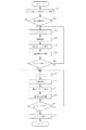
図4は、通常間引き処理を行う場合の1走査分の印字データ受信から印字データ処理終了までを示すフローチャートである。
【0066】
ステップS1では、各色のインクに対応する1走査の印字に必要な量の印字データを受信する。1走査の印字には1バンド分のデータに加え、次のバンドのドットカウント領域分のデータが必要となる。ここで、1バンドとは1回のキャリッジ走査において形成される印字領域のことである。
【0067】
印字データの受信後、単位領域、ここでは、図5に示した16ドット×16ラスターの領域毎に、ステップS2でドットカウント、ステップS3で色域判定、ステップS4で間引きランク決定、ステップS5でSMS間引き処理を行う。ステップS6では、上記の処理を1バンド分終了するまで繰り返す。1バンド終了後、ステップS7では1バンドを印字する。以下に、各処理の詳細について説明する。
【0068】
(ドットカウント)
本実施例において、ドットカウントを行う領域はバンドのつなぎ部分を含む16ラスター分の幅とする。
【0069】
ドットカウントは、本実施例に用いる記録装置が搭載している記録インク全て、すなわち、シアン、マゼンタ、イエローの各色の2値データにおいて行い、それぞれから得られたドットカウント数の総和を、ドットカウントの結果のドットカウント値(もしくはトータルドットカウント値)とする。
【0070】
ここでドットカウント値について補足すると、「ドットカウント値が1である」とは、1画素にドットが一つ存在する状態であり、2なら1画素にドットが二つ存在する状態であることを示している。
【0071】
ドットカウントは、つなぎ部近傍の分割された領域において実施し、その大きさとしては、排紙方向に16ラスター、キャリッジ走査方向に16ドット分の大きさの領域(以下「ドットカウント単位領域」とも表記する。)とする。このため、トータルドットカウント値の最大値は、16(ラスター)×16(ドット)×3(色数)=768となる。
【0072】
本実施例の処理は、このドットカウントにより得られるトータルドットカウント値から、間引きランクを決定、SMS間引き処理実施という流れで行う。また、各色のドットカウント値から単位領域に打ち込まれる各インクの量の相対関係を示す相対情報を獲得することが可能となり、この相対情報から単位領域の色域(色相と彩度)を判定している。
【0073】
このような処理を、1バンド分全てにおいて繰り返し行い、さらに1ページ分の全てのバンドに対して処理を行うことで、印字データを生成する。
【0074】
このため例えば、1バンドを形成するのに、360dpi、A4フルスキャン(8インチ)の場合には、360(dpi)×8(インチ)÷16=180となり、180回の計算を行うことになる。
【0075】
ここでトータルドットカウント値として、本実施例においては単純にシアン、マゼンタ、イエローのドットカウント値の総和としているが、色によってつなぎスジの発生への影響度が違う場合には各色毎に重みをつけても良い。例えば、イエローインクが入るとつなぎスジの程度は悪化するようなら、イエローのドットカウント値だけドットカウント値に対して重み付けしてもよいし(例えばイエローのドットカウント値のみ1.2倍する)、また色により吐出量が異なる(例えばある色だけ吐出量が大きい)などの条件があるならば、それも考慮に入れてもよいことはもちろんである。
【0076】
以上のようなドットカウント処理によれば、1バンドのうちつなぎ部近傍(すなわちノズル端部)にある小領域のデータ処理ですむので、処理にかかる負荷は小さく、1パスのようにスピードを重視する関係上、その処理に当てられる時間が短い場合においても十分処理することができる。
【0077】
また、つなぎ部を跨いだ16ドット×16ドットの領域をドットカウント単位領域とした理由について説明する。
【0078】
この場合、トータルドットカウント値の最大値は、16×16×3(色数)=768となる。また、1バンドを形成するのに、360dpiでは上述のとおり180回、600dpi、A4フルスキャン(約8インチ)の場合には、600(dpi)×8(インチ)÷16=300となり、300回の計算を行うことになる。具体的には、図5に示すように、レングス設定の全範囲に対して、ドットカウント単位領域毎にドットカウントを順次行い、全ドットカウント単位領域に対して計算を行うことにより、1バンド分のドットカウントを完成することができる。
【0079】
このようにつなぎ部を跨いだ領域をドットカウント単位領域とすることにより、つなぎ部前後の印字ドットの状態を把握することができる。つまり、つなぎスジが発生しやすいインク打ち込みがなされているかを判断することができ、より高精度なつなぎスジ処理を実施することが可能である。1バンド内のみでドットカウントを行う場合には、その領域内でのつなぎスジの要因となるインクにじみの量を想定することはできるが、次のバンドへの影響度を把握することはできない。次のバンドのつなぎ部近傍のインク量によりつなぎスジの発生具合は異なる。例えば、次のバンドにある程度のインクがある場合は、相互のインクにじみによりつなぎスジは発生しやすくなるが、インクが少ない場合は、先打ちのバンドのインクにじみは発生する可能性はあるものの、つなぎスジになる可能性は少ない。
【0080】
つなぎスジの発生メカニズムに関して、図13を用いて説明する。
【0081】
先打ちのバンドのインクが多少にじんだ状態で定着が促進しているところに、次のバンドの記録が行われる。そこで、次のバンド内のインクが紙内部もしくは表面に浸透していく過程で、先打ちのバンド領域内に次のバンドに新たに打ち込まれたインクが引き寄せられていくと考えられる。このとき、つなぎ部に何ら処理を施していないと、同図(a)に示すように、バンド間のつなぎ部のインク量が多くなってしまい、つなぎ部の濃度が他の部分より上がってしまうのがつなぎスジ発生の原因であると想定される。
【0082】
従って、このようなつなぎスジの発生を抑制するためには、同図(b)に示すようにつなぎスジ処理を施し、先後どちらかのバンドのインク量を低減させる、つまり印字データを間引くことが有効である。また、前後のどちらかのバンドでも良いし、双方のバンドに関して間引き処理を行っても良いのである。
【0083】
以上のように、つなぎスジの発生要因は、つなぎ部の前後のバンドのインク量に起因するものであり、つなぎ部を跨いだ領域をドットカウント単位領域とすることは、つなぎスジ処理の制御効率を向上させ、有効なつなぎ処理を実施することが可能となる。
【0084】
また、つなぎ部の前後において、ドットカウントの際に、先打ちのバンドとの後打ちのバンドとで重み付けをしても良い。例えば、つなぎスジ発生は先打ちのバンドのインク量に起因する傾向が高ければ、先打ちバンドのドットカウント値を1.2倍する等して、先打ちバンドのインク量に敏感な制御を実施するのも有効と考えられる。
【0085】
(色域判定)
色域選択のフローチャートを図7に示す。
【0086】
まず、ステップS2で各色のドットカウントを行う。ある単位領域におけるドットカウント値の一例を図8に、また、本実施例に用いる色域の区分を図9に示す。
【0087】
図8の例では、ドット数の多い順に、マゼンタ、シアン、イエローとなっている。ここで、シアン、マゼンタ、イエローのうち最も少ないイエローの部分は一般にUC(アンダーカラー:Under Color)と呼ばれる部分であり、二番目に多いシアンからUCを引いた部分が2次色(D2とも表記する。本例では青)、一番多いマゼンタから二番目に多いシアンを引いたものが1次色(D1とも表記する。本例ではマゼンタ)である。これらD1,D2,UCをステップS31で計算する。
【0088】
これらD1、D2、UCのうちで最も大きい値を取るものを判定することで、着目しているドットカウント領域(単位領域)が図9の中でどの色域にあるかを決定する(ステップS32)。本例においてはD1が三つのうちで最も大きいため、ドットカウント領域はシアンの中にある、という判定を行うことになる。
【0089】
なお、D1、D2、UCで、最も大きいものが2つ、あるいは3つ存在した場合には、色域としては、UC、D2、D1の順番(UCとD2が同じならUC、D1とD2が等しいならD2となり、実際はD1が使用されることはない。)で採用することにする。
【0090】
(間引きランクグラフ)
図10に間引きランクを決定するための間引きランクグラフの一例を示す。
【0091】
ここで、図10は縦軸に間引きランク(間引き率に対応)、横軸にトータルドットカウント値を取る。すなわち、ドットカウントにより得られた単位領域のトータルドットカウント値から、データの間引き率(SMSでいうところのカウント値)の指定を行う。
【0092】
本実施例においては間引き率として0%、12.5%、25%、37.5%、50%、62.5%、75%、87.5%、100%の9段階を設定する。このときのカウンタ値を図11に示す。また本実施例における間引きランクグラフの指定方法は、上述のとおり、スタートドット数、ドット間隔、MAXランクの三個の数値による組み合わせにより指定する。これら3つそれぞれのパラメータが間引きランクグラフのどこに対応するかも図10において合わせて示すことにする。
【0093】
本実施例においては上記のように3つのパラメータ(スタートドット数、間引き間隔、MAXランク)により間引きランクグラフを決定することにしたが、特にこの方法に限定する必要はないことはもちろんである。本実施例のような間引きランクグラフの決定だと、トータルドットカウント数と間引き率との関係が線形にしかできないので、間引きランクグラフそのものの形を規定するようにしてもよい。また間引き率も上に挙げた9段階に限定する必要もなく、必要に応じて間引き率の段階を増減させてよい。
【0094】
実際に、本実施例に用いる通常間引き処理における間引きランクグラフの一例を、図12に実線で示す。上述のとおり、間引きランクグラフは各色域毎に適切なものが設定されており、図12にはある1つの色域(シアン)での例を示している。
【0095】
本実施例においては、異なるインク毎(シアン、マゼンタ、イエロー)に間引きランクをそれぞれ指定するものとし、各間引き領域を排紙方向(副走査方向)に二つ分割し、各領域に独立した間引きランクグラフを設定している。そのため、図12では6つの間引きランクグラフ(シアンupper、シアンlower、マゼンタupper、マゼンタlower、イエローupper、イエローlower)を本実施例においては設定している。
【0096】
また、図12 においては、色域判定により判定された色域(本実施例においてはシアン)に対するグラフのみを示したが、実際にはこの組み合わせが、さらにマゼンタ、イエロー、UCに対しても存在する。
【0097】
このように異なるインク毎に間引きランクグラフを設定することで、インクによる記録媒体上での挙動の違いや、異なるインク間での明度や彩度の違いによるスジの見え方の差などに起因して生じる、使用インクの違いによるつなぎスジの程度差に対応することができる。
【0098】
また、間引きランクグラフを色毎に設定できるので、つなぎ部において記録媒体への打ちこみ順により生じる端部での色の変化に対応することができる。ここで、端部での色の変化とは先に図25を用いて説明したように、記録媒体への記録インクの打ちこみの時間差や記録媒体の性質により挙動は異なるが、本実施例のような横並びの記録ヘッドのように時間差がごく短い場合において、例えば普通紙上の同一位置にシアン、マゼンタの順番で記録を行うと、後に打たれるマゼンタの縁取りのようなものができるというものである。このような端部での色の変化がある場合に、記録インク毎に間引きを変えることにより、すなわち先のシアン、マゼンタの打ちこみ順において、マゼンタの間引きをシアンよりも上げることで、つなぎ部のスジの程度をより良好な状態にすることができる。
【0099】
(間引き処理領域)
本実施例においては、図5を用いて説明したように、1バンドのうち給紙側4ラスター分を処理することにし、主走査方向には16ドット分の領域を処理領域として指定する。さらに、処理を行う4ラスターを、さらに排紙側2ラスター(upperとも表記)、給紙側2ラスター(lowerとも表記)という2ヶ所の領域に分割し、その各々について、間引きランクを決定できるように、異なる間引きランクグラフを用意する。
【0100】
図5からもわかるように、本実施例で用いている間引き領域とドットカウント領域は、同一の領域ではなく、ドットカウント領域の一部が間引き領域となっている。このように、間引き領域とドットカウント領域は一致している必要はない。
【0101】
これは、つなぎスジの発生がつなぎ部のみで起きている単純な現象ではなく、相互のバンド間でのインクにじみや、つなぎ部から数ラスタ離れた部分からのインクのにじみ出しがドットのつながり状態に応じて、連鎖的に伝わると考えられる。例えば、つなぎ部の4ラスター分のみインクが打ち込まれる場合と、つなぎ部から8ラスター分にインクが打ち込まれる場合とでは、つなぎスジの状態は異なる。後者の方が重度のつなぎスジとなる。これはつなぎ部から数ラスタ離れた部分からのにじみが徐々に伝わってきて、つなぎ部のインク量は比較的多くなるために、よりつなぎスジが発生しやすくなったためである。従って、ドットカウント領域は間引き領域より大きく取ることが望ましく、前記のインクにじみの連鎖的な伝わりを考慮した領域とするのがより好ましい。本実施例では間引き領域の2倍の領域をドットカウント領域としている。
【0102】
また、間引き領域に関しては、つなぎスジ処理を効果的に実施するために、ある程度の大きさの領域を間引き領域にする必要はある。逆に極端に大きすぎると、間引き処理によっては間引いたことによる濃度低下を引き起こしてしまい、画像弊害である白スジを誘発する場合がある。これらの要因と、インクの特性から適切な間引き領域の幅が決定される。本実施例では、4ラスター(600dpiで約0.17mmの幅)を間引き領域としているが、つなぎスジ抑制の効果があり、且つ、白スジ誘発しない範囲の幅である。
【0103】
本実施例においては、間引き処理領域として、4ラスターを用意しそのうちを2分割することとしているが、4ラスターそれぞれに対して、つまり、4分割して間引きランクグラフを指定できるようにしてももちろんよい。
【0104】
このように、間引き領域内をさらに分割し、その各々に対して独立に間引きテーブルを指定できるようにすることにより、つなぎスジの強さに応じてより適切な間引き率および、間引き領域の設定ができるようになる。
【0105】
前記のようにつなぎスジの発生は、単純なつなぎ部のみの現象ではなく、数ラスター離れた部分からのインクのにじみ出しがドットのつながり状態に応じて、連鎖的に伝わることが要因と考えられる。従って、つなぎ部のみを処理するのではなく、その近傍をインクにじみの観点から処理した方が、より効果的であると考えられる。当然のことながら、つなぎ部の1ラスターもしくは2ラスターが最もつなぎスジの誘発原因となっている。更に、そこから1ラスタ離れた領域、2ラスタ離れた領域、3ラスター離れた領域、と距離に応じて、つなぎスジに影響する度合いが変化する。つなぎスジ近傍では、ある領域のラスターがつなぎスジ発生の要因となっているが、ラスター毎に影響度が異なるのである。
【0106】
この点から、間引き領域内を1ラスタもしくは2ラスター毎に、別々に間引きランクを決定し、そのラスターに適した間引き処理を行うことが重要である。更にはつなぎスジ部からの距離に応じて、間引きランクを決定することにより、つなぎスジ処理の精度をより向上させることができ、ラスター毎の間引き量を更に適正化できるために、今まで以上の高精度なつなぎスジ処理を行うことが可能となる。
【0107】
(SMS間引き処理)
SMS間引き処理とは、印字データがあるたびに、カウンタ(レジスタ)により指定されるカウント値(特定のビット、ここではMSB)を読み、1ならば印字データの印字を行いカウンタを右に一つ移動(シフト)する。カウンタ値が0であるなら、印字データの間引きを行いカウンタを右へ一つ移動する。カウンタは一番右まで移動すると再び一番左へと戻る。この処理を印字データがくるたび繰り返すことで、間引きドットを確定して行く処理方法である。
【0108】
SMS間引きについて、より具体的に図14および図15を用いて説明する。図14および図15において、印字データのうち、印字データを○で、また、印字するデータがないところを×で示した。また注目しているデータを太字で示した。カウンタ値については、印字を行うところを1で、印字データを間引くところを0で示し、カウンタにより指定されているカウンタ値を太字で示した。
【0109】
図14(a)において、1つ目の印字データは○であり、カウンタ値が0であるので、1つ目のデータは間引かれる。そのため、処理後の1つ目の印字データは×となり、またカウンタは右へ一つ移動する(同図(b))。次のデータは印字しないので、×そのままであり、カウンタも移動することなくそのままの位置に残る(同図(c))。3つ目の印字データでは、カウンタ値が1であるので、印字データはそのまま残り、カウンタが右へと一つ移動される。このようにして、印字データは4個に1個の割合で間引かれることになる(同図(d))。
【0110】
また図15では、間引き処理領域が4ラスタであることから、主走査方向に8ドット、排紙方向に4ラスターの領域(本実施例での間引き処理領域の主走査方向に半分にした領域)での間引き処理前と間引き処理後のデータを、間引きランクを排紙側2、給紙側4とした場合について示した。説明のため、図15(a)にあるように、排紙側のほうから第1ラスタ、第2ラスタ、第3ラスタ、第4ラスタと呼ぶことにする。
【0111】
ここで、SMS間引き処理は排紙側のラスタから、ラスタ毎に行うものとし、1つのラスタの処理をしたら、次のラスタの処理に移ることにする。このときSMSカウンタは間引きレベルが変わっても初期位置には戻さないものとしてある。また、SMSカウンタは本実施例においては間引き処理領域が1バンド内での隣の領域に移っても初期位置に返すことはせず、カウンタ位置は1バンド内においては保存する。また、異なるバンドの処理に移った場合には、カウンタ位置を初期位置に返すことにする。
【0112】
またカウンタの1バンドのはじめ処理領域での初期位置は、ランダムに指定することにする。その結果、第1ラスタから第4ラスタは同図(b)〜(e)に示すように処理がなされ、全体としては同図(f)に示すようになる。
【0113】
以上のように、本実施例の通常間引き処理によれば、つなぎ近傍の記録データの数(描画するドット数)から、着目領域の色域を判定し、この色域に応じて、使用インク毎に間引きランクを設定できる。このように設定された間引きランクにより各インク毎に間引き処理を行うことにより、1パス印字におけるバンド間でのつなぎスジの発生の程度を緩和させることができる。
【0114】
(遅延間引き処理)
次に、本実施例の特徴である遅延間引き処理について説明する。排紙スミアや、ヘッド過昇温制御、もしくは、予備吐等の通常の印字時とは異なる制御が入る場合に、その遅延時間情報から、通常間引き処理とは別に独立して、つなぎ処理制御を行う。この遅延つなぎ処理のフローチャートを図16に示す。なお、このフローチャートには図4で説明した通常間引き処理を併せて記載してある。
【0115】
あるバンドを印字する際、ステップS1でそのバンドを印字するために1走査分の印字データを受信する。この時、このバンドに先行するバンドを印字してからの遅延情報の有無をステップS11で判断する。ここでは、タイマー106のカウント値が所定値、例えば0.8秒以下の場合は遅延なしと判断する。この所定値は、遅延によるつなぎスジが現れる時間の下限値とすればよい。
【0116】
ステップS11で遅延情報がない場合はステップS2へ進み、先に説明した通常間引き処理を行うが、遅延情報がある場合はステップS12へ進み、遅延間引き処理を行う。
【0117】
ステップS12のドットカウントおよびステップS13の色域判定は、通常つなぎ処理と同様に行う。但しドットカウント領域については、図17に示す位置において行う。
【0118】
この間引き処理領域に対して、間引きランクグラフの設定を行う方法も通常つなぎ処理と同様とする。また、遅延情報が入ってきたときに実施する遅延つなぎ処理領域と、データ量のみにより制御を行うつなぎ処理領域(以下「通常つなぎ処理領域」とも表記)の関係も合わせて図17に示す。なお、あるバンドの通常ドットカウント領域と次のバンドの遅延ドットカウント領域は同じ領域としている。
【0119】
ステップS14で行う間引きランクの決定も通常間引き処理と同様であるが、間引きランクグラフは図12(a)〜(f)の点線で示すものを用いる。図から理解されるように、遅延間引き処理に用いるランクグラフは、通常間引き処理のそれよりもランクが低く(間引率が低く)設定され、つなぎ部に近いupper領域の方がlower領域よりもランクが高く設定されている。ここでは、lower領域では間引き処理を行わない(ランク0)としている。
【0120】
このように、通常のつなぎ処理とは独立して、遅延時間情報があるときのみ間引き処理を行う遅延つなぎ処理を設けることで、遅延により生じるつなぎスジの悪化にも対応することができるようになる。
【0121】
これは通常のつなぎ処理とは独立に処理することになるので、通常つなぎ処理と、遅延つなぎ処理とを別のタイミングで行うことができる。このためCPUでの処理を行う上で、効率良く処理を行うことができる。
【0122】
また、各々別のパラメータ設定をできるなど別処理として扱えるため自由度が高くかつシンプルな構成といえる。
【0123】
さらにまた、本実施例ではデータの読込み領域を印字を行う1バンド分よりも大きい領域としたので、つなぎ部近傍において読込みが複数回行われる領域が存在する。そして、通常つなぎ処理と遅延つなぎ処理でドットカウント領域を共通化してカウント回路を共有した。しかしながら、通常つなぎ処理と遅延つなぎ処理でドットカウント領域を別にして、遅延つなぎ処理用のドットカウント領域は遅延情報がある場合のみ、ドットカウントを行ってもよい。この場合、1バンド内の上端部を遅延つなぎ領域、下端部を通常つなぎ領域とすれば、1バンド分のデータの読み込みでドットカウントが可能となる。
【0124】
ここで、時間差がある場合、つなぎスジが顕著になる原因について説明する。時間差が少ない場合には、先打ち側のインクが紙に定着しきっておらず、後打ちのインクは先打ち側の部分で紙面表面にあまり定着することができない。
【0125】
一方、スキャン間に時間差が発生している場合には、先打ちのインクは紙に定着している。このため、すでに先打ちのインクが定着しているところに更に重ねて後打ちのインクが定着するため、濃度が高くなるものと考えられる。
【0126】
以上の原理により、走査間に時間差のある方がつなぎスジの程度が悪化するのではないかと考えられえる。これはマルチパス印字のほうが1パス印字よりも濃度が高くなるのと同じ現象と思われる。
【0127】
本実施例においては、遅延間引きランクを0.8秒以上の1セット持つことにしてあるが、遅延時間のレベル毎、例えば、0.8秒未満(遅延間引き処理なし)、0.8秒以上2秒未満(遅延間引きランク1)、2秒以上3秒未満(遅延間引きランク2)、3秒以上(遅延間引きランク3)のように数段階にレベルを設定し、その各々に対して間引きランクグラフを設定できるようにしても良い。このような設定を行えば、遅延時間に対しより適切な対応を取ることができる。上述の場合、遅延間引きランク2はランク1よりも間引ランクが高く(間引率が高く)なるよう設定することが望ましい。
【0128】
また、遅延つなぎ処理領域での間引きデータ取得(間引きランク決定)までの処理は、通常つなぎ処理とともに常に行っておき、実際に間引き処理を行うかどうかのみ遅延情報の有り無しに応じることとしても良い。
【0129】
本実施例の制御方法によれば、何らかの制御の割り込みにより印字ディレイが発生した場合においても、通常のつなぎ処理とは独立した遅延つなぎ処理を行うことができ、これにより、バンド間での印字遅延により生じるつなぎスジの悪化にも対応することができるようになり、バンド間でのつなぎスジの発生の程度を緩和させることができるようになる。
【0130】
(第2実施例)
本発明の第2実施例は、第1実施例と同様に、複数の記録ヘッドにより被記録媒体上に記録インクを用いて印字を行い画像を形成する記録方式に関するものである。
【0131】
本実施例に用いる記録装置の構成、間引き処理領域、SMS間引き処理は前述の第1実施例と同じである。
【0132】
(ドットカウント)
本実施例におけるドットカウント単位領域は、上記実施例1と同様とする。本実施例に用いるヘッド構成を図18( a )に示す。
【0133】
この構成では、黒のノズル数を、カラーのノズル数の倍以上とし、黒のみのデータの際には黒ノズルをフルに使って印字スピードをあげている。また、黒カラー混在のデータにおいては黒カラー間のブリードを防止するため、黒の使用ノズル数を減らし、黒とカラーの印字においては少なくとも1スキャンのブランクを与えることを行う。以上のような構成での、黒のみのデータの印字を行う場合の模式図を図18( b )に、黒、カラー混在のデータを印字した状態を図18( c )に示している。
【0134】
つなぎスジが発生しやすいのは、記録媒体上へインク量を多く吐出するカラーの印字時においてである。その際に黒の印字は、本実施例のようなノズル構成では、カラーの印字に先立って行われ、カラー印字時にはすでに黒の印字は完了し、記録媒体へ定着しているので、黒インクのつなぎスジへの寄与は少ない。
【0135】
以上により、本実施例においては、黒インクのドットカウントは行わずに、カラーインク(シアン、マゼンタ、イエロー)のみのドットカウントにより、つなぎ処理を行うこととした。
【0136】
(色域判定)
本実施例における色域の区分を図19に示す。このときの色域選択方法の一例を説明する。
【0137】
まず、色相方向の選択方法を示す。ここで、色相方向とは、図19の一番外側の円周上においてどこにあるか、すなわち1次色か、2次色か、その中間かの判定である。
【0138】
図20( a )において、横軸に1次色のドットカウント値を、縦軸に2次色のドットカウント値を示す。1次色、2次色、その中間の分割方法は、1次色のドットカウント値を2で割ったものと、2次色のドットカウント値との比較を行い、1次色を2で割ったものの方が大きいならば、色相は1次色にする。
【0139】
また1次色のドットカウント値と、2次色のドットカウント値を2で割ったものとの比較を行い、2次色のドットカウント値を2で割ったものの方が大きいならば、色相は2次色に、またそれ以外のときは中間の色相にあるとする。
【0140】
次に、彩度方向すなわち図19で中心に近いか、円周に近いかその中間かの判定を行う。
【0141】
図20( b )において、横軸に1次色と2次色のドットカウント値の和を、縦軸にUCのドットカウント値を示す。彩度方向の分割方法は、1次色と2次色のドットカウント値の和を2で割ったものと、UCの値との比較を行い、1次色と2次色のドットカウント値の和を2で割ったものの方が大きいならば、彩度は一番円周に近い側となりこの領域をドットカウント領域の色域として決定できる。
【0142】
1次色と2次色のドットカウント値の和を2で割ったものと、UCの値との比較を行い、UCの値のほうが大きく、かつUCの値を2で割ったものと、1次色と2次色のドットカウント値の和との比較を行い、UCの値を2で割ったものの方が大きいならば、彩度は一番中心に近い側となりこの領域をドットカウント領域の色域として決定でき、それ以外はその中間の領域として決定することができる。
【0143】
以上、色相、彩度の決定方法をより簡単に表現すると以下のようになる。

【0144】
(間引きランクグラフ)
本実施例に用いる間引きランクグラフの組み合わせの一例を図21に示す。
【0145】
本実施例では、図19に示した色域のうち7つの領域(シアン、マゼンタ、イエロー、青、緑、赤、UC)について使用するインク毎の間引きランクをそれぞれ指定することにし、それ以外の中間領域の間引きランクグラフについては、この7つの領域のグラフから計算によって算出することにする。このため、ランクグラフのデータ量を低減することが可能となる。
【0146】
グラフの算出方法であるが、その一例としては、色相方向の中間領域には1次色と2次色の平均を、彩度方向の中間領域では高彩度と低彩度の間引きランクの高いものを取ることとしている。
【0147】
本実施例において用意する間引きランクグラフの本数であるが、インク毎(シアン、マゼンタ、イエロー)に間引きランクを指定し、間引き領域を2分割することも考えると、7(色域)×3(インク数)×2(間引き領域の分割数)=42本必要になる。
【0148】
このうち、例えば上記色域判定で着目しているドットカウント領域が青であると判定されたなら、実際に使うのは42本のうち色域が青用の間引きランクグラフとなる。これを取り出して図21に実線で示した。また、同様に色域が赤用のランクグラフを図22に実線で示す。
【0149】
先の実施例と同様に、遅延間引き処理で用いるランクグラフを図21,22ともに破線で示した。いずれもlower領域では遅延間引きを行わず、upper領域でのみ遅延間引きを行なう。
【0150】
通常間引き処理では、この間引きランクグラフとトータルドットカウント数によりSMS間引き処理に使用する間引きランクを決定する。一方、遅延間引き処理においては、さらに遅延時間情報が0.8秒以上の時のみ遅延間引き処理を行う。
【0151】
このように、間引きランクグラフを、分割された色域全てに対して指定するのではなく、基本となる物を指定して、その中間の領域に対しては計算でグラフを算出することにすれば、データ量を減らすことができる。
【0152】
遅延間引き処理と通常間引き処理においてランク決定後は実施例1と同様に単位領域に対してSMS間引きを行い、以上を1バンド分行った後、1走査分の記録を行う。
【0153】
ここで、先に説明した白から、青そしてUC(アンダーカラー、YMCの混色)に向かうようなグラデーションにおける通常間引き処理について、図21を参照して説明する。
【0154】
青に向かうところではシアンインクとマゼンタインクを用いて印字をしており、青のMAXになった時点でシアン、マゼンタはそれぞれベタ印字のデータ(最大デューティーのデータ)、つまり本例では512となっている。この状態では、その単位領域の色域は当然青であり、図21を参照すれば、つなぎスジを緩和させるためにシアンlowerに対してはランク5(同図(a))、マゼンタlowerに対してはランク6(同図(c))の高率の間引きを適用する。一方、白から赤、そしてUCに向かうグラデーションを印字する場合を図22を参照して説明する。赤のMAXからUCに向かうポイントにおいてはじめてシアンインクを使用し始めることになる。この点での打ち込み量は、マゼンタ、イエローそれぞれの最大デューティーのデータであり、先の白−青−黒のグラデーションの場合の青から黒に向かうところと等しい512であり、色域は当然赤である。そのため、図22を参照すればシアンlowerに対してはランク3(同図(a))、マゼンタlowerに対してはランク5(同図(c))の間引き率を用いて間引きを行うことになる。このとき、データが入りはじめで、まばらな状態にしかドットが配置されていないシアンのドットはランク3の比較的低い間引きが施されるため、シアンドットの抜けが目立つといった弊害は発生しない。
【0155】
なお、上記、第1、第2実施例においてドットカウント単位領域として16ドット(主走査方向)×16ラスター(副走査方向)というものを使用しているが、特にこの大きさにこだわる必要はなく、単位領域の大きさは、つなぎスジの程度や、データの処理にかかる負荷、出力解像度等などの諸要因により決定することが望ましい。
【0156】
さらにドットカウントを行う部分であるが、第1,2実施例においては例えば図5に示したように、両方のバンド間でのつなぎ部をまたいだ領域でドットカウントを行ったが、これに限定されるものではない。先の走査の下端部のみを対象としてもよいし、つなぎ部に対し、後の走査の上端部にてドットカウント値を算出しこれにより処理を行うこととしてもよい。
【0157】
SMS間引き処理を行う部位も特に先の走査の下端部に限るというものではなく、後の走査の上端、あるいはその両方すなわち、バンド間のつなぎ部をまたいだ領域で行うとしてももちろんよい。
【0158】
このようなドットカウント領域もしくは、SMS間引き処理領域は、使用する記録媒体と、記録インクの組み合わせ等により随時最適と思われる部分を指定できるほど望ましい。そのため、用いる記録媒体に応じて、ドットカウント領域とSMS間引き処理領域、もしくはそのいずれかを適時変更するのも望ましい処理である。
【0159】
これとともに、区分する色域数であるが、本発明においては、2種類のパターンを示したが、この2つに限定されるものでないことはもちろんである。
【0160】
また、本発明においては基本的に1パスによる印字を想定してあるが、これは1パスにおいて、つなぎスジの発生が最も顕著であるからである。しかし、マルチパス印字時においてもつなぎスジは程度の差こそあるものの発生する。そのため、マルチパス用に、パス数に応じた間引きランクグラフを用意しておき、それを用いてマルチパス印字時においても間引き処理を行うことも有効である。
【0161】
つなぎスジは、記録媒体上での記録インクのにじみによるところがあるので、例えば高温多湿の環境においては記録インクのにじみ具合は大きくなりつなぎは厳しくなる(より目立つ)。そこで、使用する外部環境に応じて、間引きランクグラフや、間引き領域を変更する閾値を複数持っておき、可変できるようにすることは有効である。
【0162】
上記実施例の構成では、使用する記録インクはシアン、マゼンタ、イエロー、黒としているが、通常の所謂レギュラーインクを希釈したフォトインクと呼ばれるものを用いるシステムにおいても本提案は使用することができる。
【0163】
さらに、上述の実施例では各インクの打ち込み量に関するデータとしてY,M,Cの2値データの形態を例に挙げて説明したが、本発明はこれに限定されるものではない。インクの打ち込み量に対応するデータであれば、R,B,Gの多値データであってもよい。この場合、インク量はデータの間引きによって低減するのではなく、多値のデータに低減係数をかけても良い。
【0164】
また、走査間隔情報としては、キャリッジ走査方向の印字データ長を取得して、これによりつなぎ部分の印字時間間隔を求めても良い。これは、キャリッジ走査自体にも時間を要するため、キャリッジ走査速度や記録媒体の幅によっては走査間隔がつなぎスジの生じる時間となる場合があるからである。さらに、双方向印字を行う場合は、記録位置と走査方向によっては大幅な時間間隔が生じるため、これらの情報から印字時間間隔を求めても良い。これらの場合、上述の実施例のように1バンドを複数の単位領域に分割している場合は、単位領域毎に遅延間引きランクを変更することが容易となり、1バンド内での遅延間引き処理を行うことが可能となる。
【0165】
さらに、本実施例は色域を判定し、これに基づいて間引き処理を行っているが、本発明はこれに限定されるものではない。単につなぎ部分の印字デューティーに基づいて間引き処理を行うものにおいて、さらに走査間隔情報に基づいて間引き処理を行うもでも良く、さらには、単に走査間隔情報に基づいて間引き処理を行うものでもよい。
【0166】
また、上記実施例では図26(a)に示すように、先打ち下端で通常間引き処理、後打ち上端で遅延間引き処理を行ったが、本発明はこれに限定されるものではない。
【0167】
すなわち、同図(b)に示すように先打ち下端での通常および遅延一括処理や、同図(c)に示すように後打ち上端での通常および遅延一括処理であってもよい。一括処理のため、処理の高速化や簡易化が図れる利点がある。
【0168】
反面、同図(b)の方法では遅延時間の情報を印字前に取得することが前提となる。しかし、遅延が発生する原因はさまざまある。スキャン間ディレイや、スミア制御ならばデータの先読みにより時間を予測することは可能であるが、昇温や、データ転送待ちあるいは量子化処理待ち等による遅延の場合は、その遅延が果たしてどのくらいとなるのか正確に把握するのは難しい。
【0169】
遅延も終わった状態で処理を行う同図(c)という方法も考えられるが、後打ち上端の処理は、先打ち下端の処理に比べて、使用する紙により影響を大きく受け、処理を有効に実施することが難しい。
【0170】
同図(a)の方法ならば、遅延時間を取得するための先読みの必要が無く、また遅延が発生した場合にだけ通常の処理とは独立に処理することができるなどから、他の方法に比べて実施に向いているといえる
この様に通常つなぎ処理を行う領域を上記のように給紙側とするのではなく、排紙側とした場合でも、本発明のような処理は行うことができる。この場合には一度通常つなぎ処理を行った領域に対し場合によってはさらに処理をかけることで可能である。このときの処理領域や間引きパラメータは、通常処理と遅延処理とで同じにする必要は特にないのはもちろんである。
【0171】
(その他)
なお、本発明は、特にインクジェット記録方式の中でも、インク吐出を行わせるために利用されるエネルギとして熱エネルギを発生する手段(例えば電気熱変換体やレーザ光等)を備え、前記熱エネルギによりインクの状態変化を生起させる方式の記録ヘッド、記録装置において優れた効果をもたらすものである。かかる方式によれば記録の高密度化、高精細化が達成できるからである。
【0172】
その代表的な構成や原理については、例えば、米国特許第4723129号明細書、同第4740796号明細書に開示されている基本的な原理を用いて行うものが好ましい。
【0173】
この方式は所謂オンデマンド型、コンティニュアス型のいずれにも適用可能であるが、特に、オンデマンド型の場合には、液体(インク)が保持されているシートや液路に対応して配置されている電気熱変換体に、記録情報に対応していて、書く沸騰を超える急速な温度上昇を与える少なくとも一つの駆動信号を印可することによって、電気熱変換体に熱エネルギを発生せしめ、記録ヘッドの熱作用面に膜沸騰を生じさせて、結果的にこの駆動信号に一対一で対応した液体(インク)内の気泡を形成できるので有効である。この気泡の成長、収縮により吐出用開口を介して液体(インク)を吐出させて、少なくとも一つの滴を形成する。この駆動信号をパルス形状とすると、即時適切に気泡の成長収縮が行われるので、特に応答性に優れた液体(インク)の吐出が達成でき、より好ましい。このパルス形状の駆動信号としては、米国特許第4463359号明細書、同第4345262号明細書に記載されているようなものが適している。なお、上記熱作用面の温度上昇率に関する発明の米国特許第4313124号明細書に記載されている条件を採用すると、さらに優れた記録を行うことが出来る。
【0174】
記録ヘッドの構成としては、上述の各明細書に記載されているような吐出口、液路電気熱変換体の組合わせ構成(直線状液流路または直角液流路)の他に熱作用部が屈曲する領域に配置されている構成を開示する米国特許第4558333号明細書、米国特許第4459600号明細書を用いた構成も本発明に含まれるものである。加えて、複数の電気熱変換体に対して、共通するスリットを電気熱変換体の吐出部とする構成を開示する特開昭59−123670号公報や熱エネルギの圧力波を吸収する開口を吐出部に対応させる構成を開示する特開昭59−138461号公報に基づいた構成としても本発明の効果は有効である。すなわち、記録ヘッドの形態がどのようなものであっても、本発明によれば記録を確実に効率よく行うことが出来るようになるからである。
【0175】
加えて、上例のようなシリアルタイプのものでも、装置本体に固定された記録ヘッド、あるいは装置本体に装着されることで装置本体との電気的な接続や装置本体からのインクの供給が可能になる交換自在のチップタイプの記録ヘッド、あるいは記録ヘッド自体に一体的にインクタンクが設けられたカートリッジタイプの記録ヘッドを用いた場合にも本発明は有効である。
【0176】
また、本発明の記録装置の構成として、記録ヘッドの吐出回復手段、予備的な補助手段等を付加することは本発明の効果を一層安定出来るので、好ましいものである。これらを具体的にあげれば、記録ヘッドに対してのキャッピング手段、クリーニング手段、加圧あるいは吸引手段、電気熱変換体或いはこれとは別の加熱素子或いはこれらの組み合わせを用いて加熱を行う予備加熱手段、記録とは別の吐出を行う予備吐出手段をあげることができる。
【0177】
また、搭載される記録ヘッドの種類ないし個数についても、例えば単色のインクに対応して1個のみが設けられたもののほか、記録色や濃度を異にする複数のインクに対応して複数個設けられるものであっても良い。すなわち、例えば記録装置の記録モードとしては黒色等の主流色のみの記録モードだけではなく、記録ヘッドを一体的に構成するか複数個によるかのいずれでも良いが、異なる色の複数カラー、または、混色によるフルカラーの各記録モードの少なくとも一つを備えた装置にも本発明はきわめて有効である。
【0178】
さらに加えて、以上説明した本発明実施例においては、インクを液体として説明しているが、室温やそれ以上で固化するインクであって、室温で軟化もしくは液化するものを用いてもよく、あるいはインクジェット方式ではインク自体を30℃以上70℃以下の範囲内で温度調整を行ってインクの粘性を安定吐出範囲にあるように温度制御するものが一般的であるから、使用記録信号付与時にインクが液状をなすものを用いてもよい。加えて、熱エネルギによる昇温を、インクの固形状態から液体状態への状態変化のエネルギとして使用せしめることで積極的に防止するため、またはインクの蒸発を防止するため、放置状態で固化し加熱によって液化するインクを用いてもよい。いずれにしても熱エネルギの記録信号に応じた付与によってインクが液化し、液状インクが吐出されるものや、記録媒体に到達する時点ではすでに固化し始めるもの等のような、熱エネルギの付与によってはじめて液化する性質のインクを使用する場合も本発明は適用可能である。このような場合のインクは、特開昭54−56847号公報あるいは特開昭60−71260号公報に記載されるような、多孔質シート凹部または貫通孔に液状または固形物として保持された状態で、電気熱変換体に対して対向するような形態としてもよい。本発明においては、上述した各インクに対してもっとも有効なものは、上述した膜沸騰方式を実行するものである。
【0179】
さらに加えて、本発明インクジェット方式の形態としては、コンピュータ等の情報処理機器の画像出力端末として用いられるものの他、リーダ等と組み合わせた複写装置、さらには送受信機能を有するファクシミリ装置の形態を採るもの等であってもよい。
【0180】
【発明の効果】
以上説明したように本発明によれば、走査(バンド)間の走査間隔情報に基づいて境界部近傍におけるインクの間引き量を決定しているので、走査間隔が一定でなくてもバンド間でのつなぎスジの発生を緩和することができる。
【図面の簡単な説明】
【図1】本発明の一実施例に係わるインクジェット記録装置の概略構成を一部破断で示す斜視図である。
【図2】図1に示した記録ヘッドの主要部の構造を模式的に示す斜視図である。
【図3】本発明の一実施の形態に係るインク・ジェット・プリント装置における制御回路の概略構成を示すブロック図である。
【図4】本発明の第1実施例における処理の手順を示すフローチャートである。
【図5】本発明の第1実施例における印字データのドットカウントを行う領域と間引きを行う領域を説明する図である。
【図6】本発明の第1実施例における記録ヘッドの構成を示す模式図である。
【図7】本発明の第1実施例における色域判定の手順を示すフローチャートである。
【図8】本発明の第1実施例におけるある単位領域におけるドットカウント値の一例を示す模式図である。
【図9】本発明の第1実施例における色域の区分の一例を示す図である。
【図10】本発明の第1実施例における間引きランクグラフの一例である。
【図11】本発明の第1実施例におけるSMS処理のカウンタ値の一例である。
【図12】本発明の第1実施例における間引きランクグラフの一例である。
【図13】バンドのつなぎ部ににじみが生じる原理を説明する図である。
【図14】本発明の第1実施例におけるSMS処理による印字データの処理を説明するため図である。
【図15】本発明の第1実施例におけるSMS処理による印字データの処理を説明するため図である。
【図16】本発明の第1実施例における遅延間引き処理の手順を示すフローチャートである。
【図17】本発明の第1実施例における間引き領域を説明するための図である。
【図18】本発明の第2実施例における記録ヘッドの構成を示す模式図である。
【図19】本発明の第2実施例における色域の区分の一例を示す図である。
【図20】本発明の第2実施例における色域内での分割方法の一例を説明するための図である。
【図21】本発明の第2実施例における間引きランクグラフの一例である。
【図22】本発明の第2実施例における間引きランクグラフの一例である。
【図23】本発明の実施の形態におけるバンドおよび境界部を説明するための概念図である。
【図24】本発明の実施の形態におけるマスクによる間引き処理を説明するための概念図である。
【図25】本発明の実施の形態における被記録媒体上での記録インクを説明するための概念図である。
【図26】本発明の間引き処理領域を説明するための図である。
【符号の説明】
1、1A、1B、1C ヘッドカートリッジ
2 キャリッジ
4 主走査モータ
8 記録媒体
13 記録ヘッド部
22 吐出口
100 コントローラ
101 CPU
103 ROM
105 RAM
106 タイマー
110 ホスト装置[0001]
BACKGROUND OF THE INVENTION
The present invention relates to an ink jet recording method, a recording apparatus, and a data processing method capable of obtaining a high-quality image on a recording medium, and more specifically, an ink jet recording method for performing color recording by a recording head in one pass or multiple passes. The present invention relates to a recording apparatus and a data processing method.
[0002]
The present invention is applicable to all devices using recording media such as paper, cloth, leather, non-woven fabric, OHP paper, and metal. Specific examples of applicable equipment include office equipment such as printers, copiers, and facsimile machines, and industrial production equipment.
[0003]
[Prior art]
In recording on a recording medium by a recording apparatus, there is an increasing need for users who want to print at high speed. When printing with an emphasis on speeding up, a method of reducing the number of passes in multi-pass printing that is used to achieve high image quality is effective. Here, the number of printing passes is the number of times the carriage is scanned to complete one line.
[0004]
This is because the number of ejection ports of the recording head is a fixed value, so the larger the number of passes, the smaller the paper feed amount per one time. Conversely, the smaller the number of passes, the smaller the amount of paper feed per time. This is because it can be enlarged. For example, if it is possible to print in one pass where printing by two passes is performed, the speed can be increased approximately twice. In other words, the smaller the number of passes, the smaller the number of carriage scans required to record a predetermined area (for example, one sheet), and the larger the amount of paper feed that can be done, resulting in printing one sheet. Such time is shortened.
[0005]
When printing is performed in one pass, the recording head having a plurality of ejection openings for ejecting recording liquid (ink) is scanned in a direction substantially perpendicular to the arrangement direction of the ejection openings. As a result of this scanning, a band-shaped image region (band) is formed as shown in FIG.
[0006]
In this way, when printing in one pass, since one band area is formed by one scan, a plurality of areas where the duty (ratio) of the recording ink that is driven onto the recording medium at one time is one band are plural. More than multi-pass printing formed by one scan. For this reason, although the degree of difference varies depending on the properties of the recording medium and the recording liquid, black streaking between passes (between bands) becomes remarkable in a portion with a high printing duty in one-pass printing.
[0007]
This adverse effect becomes even greater in a so-called side-by-side head configuration in which recording heads that discharge a plurality of different recording inks (cyan, magenta, yellow, etc.) are arranged in the main scanning direction. This is because the connecting position of each color occurs in the same place. A schematic diagram of the recording heads arranged side by side is shown in FIG.
[0008]
The black streaks generated at the boundary between the band and the band as described above are also referred to as connecting streaks or banding, and if this connecting streaks occur, the print quality may be difficult to withstand actual use.
[0009]
For this reason, a method has been proposed in which such connecting stripes are eliminated and image quality is improved in one pass.
[0010]
For example, JP-A-11 − In the 188898 publication, when the recording head repeatedly scans in the main scanning direction and records an image for each band in the serial scanning method, a streak is not generated at the joint portion of the recording area for each band. The method of making is described. That is, at least one of the first raster and the final raster of one band recorded by one scan of the recording head is divided into a plurality of unit areas composed of a predetermined number of dots, and each unit is determined based on the image data. In this method, printing is performed by thinning out the ink discharge amount of interest in accordance with the sum of the ink discharge amount (duty) of the color of interest in the region and the other ink discharge amounts in the unit region. .
[0011]
[Problems to be solved by the invention]
However, according to the conventional method, for example, in printing on a recording medium such as plain paper in which a connecting stripe is likely to occur, the accuracy of reducing the connecting stripe is not sufficient, and the connecting stripe may be conspicuous in the printed image. there were.
[0012]
According to the study by the present inventors, it has been found that the degree of occurrence of the connecting stripe depends not only on the band end duty but also greatly influenced by the difference in the printing time between the bands. For example, if control is performed to put a delay between print scans in order to prevent paper smearing and head overheating in the middle of printing, the connecting stripes where the delay entered will continue at the normal printing speed. This is more prominent than when printing was performed. For this reason, in the joining process set assuming the normal printing speed without considering the delay, the generation of the joining stripe cannot be sufficiently reduced, and further improvement in the printing quality is desired.
[0013]
Further, if the carriage scan width is large, a time difference occurs at both ends. For example, if the carriage speed is 8 inches / second, one scan takes 1 second with A4 full page (8 inches). Due to this time difference, when reciprocal printing is performed, a time difference of up to 2 seconds is generated, and the degree of occurrence of the connecting stripes may be different.
[0014]
The present invention has been made in order to solve the above-described problems, and an object of the present invention is to provide an ink jet recording apparatus capable of obtaining an image with less connecting stripes when the scanning interval between bands is not constant, It is to provide a recording method and a data processing method.
[0015]
Another object of the present invention is to provide an ink jet recording apparatus, a recording method, and a data processing method capable of obtaining a color image with little stitching when printing in one pass bidirectional.
[0016]
[Means for Solving the Problems]
In order to achieve the above-described object, the present invention provides an inkjet recording apparatus that performs recording on a recording medium in units of bands by ejecting ink from a plurality of ejection openings while scanning the recording head relative to the recording medium. , Scanning with the recording head Recording a band adjacent to the band recorded by the scan Next scan When Based on the acquisition means for acquiring the scanning interval information related to the time difference, and the scanning interval information acquired by the acquisition means, Between the two bands And a reduction unit that performs a process for reducing the amount of ink that is ejected in the vicinity of the joint, and the reduction unit is configured so that the time difference is a first time. Two Above Between the bands The amount of ink to be ejected in the vicinity of the joint is made larger than that in the second time in which the time difference is shorter than the first time.
[0017]
The present invention is also an ink jet recording apparatus that performs recording on a recording medium by ejecting a plurality of inks of different colors while scanning the recording head relative to the recording medium, and scanning with the recording head. Recording a band adjacent to the band recorded by the scan Next scan When Acquisition means for acquiring scanning interval information related to the time difference between the recording head and the recording head to record the information on the recording medium Two of the above band while For each unit area obtained by dividing the vicinity of the joint portion into a plurality of areas, acquisition means for acquiring relative information indicating a relative relationship between the amounts of ink to be driven into the unit area, and acquisition means for acquiring the relative information. Simply A reduction rate for reducing the amount of ink to be ejected in the vicinity of the joint portion in the unit area based on the relative information for each position area and the amount information indicating the sum of the amounts of inks to be ejected into the unit area A In the case where the determination means for each ink and information indicating that the scanning interval information acquired by the acquisition means is longer than a predetermined time, the connection is performed based on the reduction rate for each ink determined by the determination means. And a reduction means for performing a reduction process for reducing the amount of each ink to be ejected in the vicinity of the portion.
[0018]
According to the above configuration, by performing the thinning process on the recording data in the vicinity of the connection based on the scanning interval information, it is possible to obtain an image with less connecting stripes when the scanning interval between the bands is not constant.
[0019]
In addition, the color gamut (hue and saturation) of the unit area (target area) is determined from the number of print data (number of dots to be drawn) in the vicinity of the joint, and for each ink used and each print position according to this color gamut. You can set a thinning rank. By performing the thinning process for each ink using the thinning rank set in this way, it is possible to alleviate the degree of joint streaks that occur between bands in one-pass printing.
[0020]
DETAILED DESCRIPTION OF THE INVENTION
Hereinafter, embodiments of the present invention will be described by taking a serial printer having a plurality of recording heads as an example.
[0021]
In one embodiment of the present invention, in the data for one band, the vicinity of the connecting portion is divided into certain unit areas, the number of dots of each color is counted for each area, and attention is paid from the dot count value for each color. The color gamut of the area is determined. In this color gamut, a thinning processing area (particularly, for each color) is obtained from the dot count value (or print duty) for each unit area obtained by the sum of the dot count values for each color and the thinning rank graph given in advance. Determine the thinning rank of the lower end of the band) and execute the SMS thinning process. Hereinafter, this joining process is referred to as a normal joining process.
[0022]
In the present embodiment, similarly to the normal joining process, the thinning rank (in particular, the upper end part of the next band) is designated for each ink in the vicinity of the joining part based on the scanning interval information. Perform SMS thinning process. Hereinafter, this connection process is referred to as a delay thinning process.
[0023]
Here, it supplements about the following points in the said form.
[0024]
(Scanning interval information)
The scan interval information used in the delay thinning process is related to the delay time and the amount of print data when a delay is added between print scans to improve fixing and prevent discharge smear, and to prevent excessive head temperature rise. It includes data transfer time and data processing time information for print data creation. Furthermore, information on the print position and the scan direction for considering the time difference between scans due to the time required for carriage scanning is also included in the scan interval information. Alternatively, it may be the length of print data for one scan.
[0025]
That is, information directly or indirectly related to the time required for printing a connection between one scan and the next scan is included in the scan interval information of the present invention even if it is not direct time information. .
[0026]
(Thinning processing position)
As shown in FIG. 5, the normal thinning-out area is the number of rasters on the feed side (for example, 4 rasters) in one scan for printing. The reason for thinning the paper supply side is that the paper discharge side has a relatively large margin (margin) with respect to the recording medium than the paper supply side. By thinning out the paper supply side, it is possible to support a relatively larger number of recording media than by thinning out the paper discharge side by one parameter.
[0027]
The area where the delay thinning process is performed is the number of discharge side rasters (for example, 4 rasters) in one scan for printing. The reason for thinning out the paper discharge side is that the delay time is generally determined immediately before performing a certain scan, and therefore, when thinning out in the subsequent scan, the connecting portion is on the paper discharge side.
[0028]
In addition, when thinning is performed over several rasters, the degree of thinning (here, a rank graph) is set independently for each raster or in units of several rasters (in this case, two upper and lower two raster units). For example, by setting the thinning level to be higher in the portion closer to the connection, it is possible to increase the thinning accuracy, that is, the thinning processing accuracy.
[0029]
(Dot count area)
As shown in FIG. 5, the area where dot count is performed is 16 dots straddling the connecting portion in both normal thinning processing and delay thinning processing. × The area is 16 rasters (dots). Although details will be described later, it is possible to appropriately grasp the bleeding state in the joint portion by making the area larger than the thinning region and dot-counting the print data of both bands across the joint portion.
[0030]
In the normal thinning process and the delay thinning process, the same area is dot-counted. However, when the thinning is performed at the connecting portion of the preceding band in the normal thinning process, the dot count is performed again. In addition, when the delay time is short, no connection streaks due to delay occur, so no delay thinning process is necessary, and naturally no dot count is necessary.
[0031]
(Thinning processing method)
In the present embodiment, the print data thinning process is executed using a thinning method called SMS (sequential multi-scan) thinning process. Other thinning processing methods include a pattern mask method and error diffusion (ED).
[0032]
However, as shown in FIG. 24, for example, the pattern mask method uses the zigzag array thinning mask shown in FIG. 24A (thinning out the pixel data of the white portion), as shown in FIG. ) And (b-2), when print data having the same driving amount is processed, the processed data becomes (c-1) and (c-2). × The print data corresponding to the grid indicated by is thinned out. As can be seen from these two figures, the pattern mask method is simple in configuration, but the thinning mask and the print data interfere with the data of the same recording ink ejection amount (duty) depending on the print data arrangement. In some cases, the thinning amount cannot be controlled uniformly.
[0033]
Moreover, although it is the method by ED, the following operation can be considered as an example of this.
・ If there is data to be printed on the pixel that processes quantized image data, multi-values are assigned based on the nozzle correction value obtained in advance.
・ Add errors from surrounding pixels
・ Determine whether or not to thin out the print data of pixels by comparing with a predetermined threshold
・ Calculate the error caused by the judgment
・ Distribute the error to surrounding pixels
If there is no data to be printed on the pixel that performs the processing of the quantized image data, an error from the surrounding pixels is acquired and distributed to the predetermined surrounding pixels.
The pixel to which the error is distributed is that the error is distributed to at least one of the pixels in the data string to be processed next, as viewed from the data string of the pixel in the scanning direction of the connecting stripe process and the other pixel being processed. .
[0034]
However, such processing can perform proper thinning, but when trying to perform one-pass printing, there are cases where the number of nozzles in the current high-density nozzle head is large and the processing of the print data is not in time. You can easily imagine what to do. When waiting for data processing, a phenomenon of carriage stoppage due to print data waiting is caused, which is contrary to the purpose of speeding up printing by performing one-pass printing.
[0035]
For this reason, in this embodiment, the SMS thinning process is adopted in order to achieve uniform control of the thinning amount and high-speed processing. Here, the SMS thinning process reads the count value (specific bit, for example, MSB) specified by the counter (register) every time print data exists. If it is 1, the print data is not thinned (printing) On the other hand, if the counter value is 0, the print data is thinned out (printing is not performed). Then, the counter is moved to the right by one (bit shift). When the counter moves to the rightmost position, it returns to the leftmost position again (shifts cyclically). This is a processing method in which thinning dots are determined (thinning processing) by repeating this processing every time print data comes. As described above, since only thinning or non-thinning is determined for a certain dot of print data, there is no synchronization with the print data pattern.
[0036]
(Thinning table)
The color development at the printing edge varies depending on the printing order of the ink used on the recording medium. An example of the penetration of the recording ink into the recording medium is schematically shown in FIG. However, the state of penetration of the recording ink differs depending on the recording ink used, the recording medium, the environment, the printing time difference between the recording inks for printing, and the like.
[0037]
Here, a state is shown in which the
[0038]
Next, FIG. 10A shows an example of a thinning rank graph for determining the thinning rate in the present embodiment. This thinning rank graph shows the thinning rank corresponding to the dot count number in the dot count area for each ink to be thinned.
[0039]
The thinning rank graph is specified by a combination of three numerical values: the number of start dots, the dot interval, and the MAX rank. The thinning rank is designated in advance. For example, in the present invention, the thinning rate is 0%, 12.5%, 25%, 37.5%, 50%, 62.5%, 75%, 7.5%, 100%.
[0040]
Each parameter will be described first. The number of start dots is the total dot count value when starting to use a thinning rate of 12.5% (thinning rank 1). The dot interval means a dot count number until the next thinning rate (25% if 12.5% is followed), that is, a range of dot counts using the same thinning rate. The MAX rank is the maximum thinning rate, and if the thinning rate reaches the MAX rank without selecting a thinning rate exceeding this, even if the dot count value for the dot interval comes after that, the thinning rate is increased. It means that the thinning rate of MAX rank is maintained without doing.
[0041]
If it is possible to set with three parameters in this way, for example, one thinning rank graph such as 3 dots for start dots (8 steps), 3 bits for dot interval (8 steps), and
[0042]
In order to increase the resolution of each parameter, the number of bits of the parameter may be increased. Alternatively, the parameter can be set with higher accuracy by leaving the number of bits as it is, and giving a common offset for the thinning rank graph in 1 byte for each of the start dot number, dot interval, and MAX rank. .
[0043]
In this way, it is possible to reduce the amount of data necessary to set the thinning rank graph. As described above, reducing the amount of data is very important in the present embodiment. This is because, in a printing mode with a high printing speed such as one pass, it is difficult to implement with a software and a hardware implementation is desirable in order to perform a linkage process as in this embodiment. This is because when data processing is performed with software, data cannot be generated in time for the printing speed of the carriage, and print data waits. For this reason, it is desirable to implement in hardware, that is, a gate array. However, since the required number of data directly affects the number of gates, the smaller the number of data, the better in terms of circuit scale.
[0044]
Another example of the thinning rank is shown in FIG. This is effective when it is desired to change the inclination in the middle of the thinning rank graph.
[0045]
In addition to the three parameters required to describe the thinning rank of the previous point, in order to specify the second slope, the number of changed dots indicating the start point of the change and the
[0046]
(Color gamut judgment)
Depending on the relationship between the ink used and the recording medium, the behavior on the recording medium will differ when printing is performed, and the appearance of the connecting stripe and the effect on the connecting stripe when thinned will differ depending on the color. .
[0047]
For example, in a gradation that goes from white to blue and UC (mixed color of under color and YMC), printing is performed using cyan ink and magenta ink in the direction toward blue, and when the maximum of blue is reached. Cyan and magenta are solid print data (maximum duty data). In this state, thinning is applied to some extent to cyan and magenta in order to reduce the connecting stripes.
[0048]
Consider the case of printing gradation from white to red and then to UC using the same thinning parameters. It will begin using cyan ink only at the point from red MAX to UC. The driving amount at this point is the maximum duty data for magenta and yellow. − Blue − Since it is equal to the direction from blue to black in the case of black gradation, thinning is performed using the high thinning rate used previously for cyan and magenta. For this reason, since a large amount of cyan dots are extracted when data starts to enter and dots are arranged only in a sparse state, there is a problem that cyan dot omission is noticeable.
[0049]
In this way, in addition to the total amount of ink applied to the unit area in the vicinity of the edge used in the past, information on the hue and saturation of the unit area and information on which printing ink is used for printing are obtained. Therefore, it is necessary to set the thinning rate according to the information in performing the joining process when forming a color image. In order to realize this, in the present embodiment, the hue and saturation of the region of interest (unit region) are determined from the dot count value of each color. Hereinafter, the hue and saturation are collectively referred to as a color gamut.
[0050]
According to the above embodiment, the color gamut of the region of interest is determined from the number of print data in the vicinity of the connection (the number of dots to be drawn), and the thinning rank (thinning-out) is determined for each ink used and each print position according to this color gamut. By using the thinning rank set in this way and performing the thinning process for each ink, the degree of joint streaks that occur between bands in one-pass printing can be reduced. .
[0051]
Hereinafter, embodiments of the present invention will be described in detail with reference to the drawings. In each figure, elements indicated by the same reference numerals are the same or corresponding elements.
[0052]
(First embodiment)
The first embodiment of the present invention relates to a recording method in which a plurality of recording heads print on a recording medium using recording ink to form an image. First, the normal joining process will be described, and then the delay joining process that is a feature of the present embodiment will be described.
[0053]
(Configuration example of recording device)
FIG. 1 is a schematic perspective view showing a main configuration of an embodiment of an ink jet recording apparatus to which the present invention is applied. In FIG. 1, a plurality (three) of head cartridges 1A, 1B, and 1C are mounted on a
[0054]
The plurality of
[0055]
The
[0056]
The
[0057]
FIG. 2 is a schematic perspective view partially showing a main part structure of the
[0058]
FIG. 3 shows a schematic configuration example of a control circuit in the ink jet printing apparatus shown in FIG.
[0059]
In FIG. 3, a
[0060]
The
[0061]
The operation unit 120 is a switch group that receives an instruction input from the operator, and includes a
[0062]
The
[0063]
The
[0064]
The
[0065]
(Print data processing)
FIG. 4 is a flowchart showing the process from reception of print data for one scan to the end of print data processing when normal thinning processing is performed.
[0066]
In step S1, print data of an amount necessary for one-scan printing corresponding to each color ink is received. For one-scan printing, in addition to data for one band, data for the dot count area of the next band is required. Here, one band is a print area formed in one carriage scan.
[0067]
After receiving the print data, the unit area, here 16 dots shown in FIG. × For each area of 16 rasters, dot count is performed in step S2, color gamut determination is performed in step S3, thinning rank is determined in step S4, and SMS thinning is performed in step S5. In step S6, the above process is repeated until one band is completed. After the end of one band, one band is printed in step S7. Details of each process will be described below.
[0068]
(Dot count)
In this embodiment, the dot count area has a width corresponding to 16 rasters including the band connecting portion.
[0069]
Dot counting is performed on all the recording inks installed in the recording apparatus used in this embodiment, that is, binary data for each color of cyan, magenta, and yellow, and the total dot count obtained from each is calculated as dot count. The resulting dot count value (or total dot count value).
[0070]
Here, supplementing the dot count value, `` dot count value is 1 '' means that there is one dot per pixel, and if it is 2, it means that there are two dots per pixel. Show.
[0071]
The dot count is performed in the divided area in the vicinity of the connecting portion. The size is 16 rasters in the paper discharge direction and 16 dots in the carriage scanning direction (hereinafter referred to as “dot count unit area”). Notation.) For this reason, the maximum total dot count value is 16 (raster). × 16 (dots) × 3 (number of colors) = 768.
[0072]
The processing of this embodiment is performed according to the flow of determining the thinning rank from the total dot count value obtained by this dot count and performing the SMS thinning processing. In addition, it is possible to obtain relative information indicating the relative relationship between the amounts of inks that are shot into the unit area from the dot count value of each color, and the color gamut (hue and saturation) of the unit area is determined from this relative information. ing.
[0073]
Such processing is repeated for all the bands, and print data is generated by performing processing for all the bands for one page.
[0074]
Therefore, for example, in the case of 360 dpi and A4 full scan (8 inches) to form one band, 360 (dpi) × 8 (inch) ÷ 1 6 = 180, and 180 calculations are performed.
[0075]
In this embodiment, the total dot count value is simply the sum of the dot count values of cyan, magenta, and yellow. However, if the degree of influence on the occurrence of streaks differs depending on the color, a weight is assigned to each color. You can put it on. For example, when yellow ink enters, the level of connecting stripes deteriorates Ru In other words, the dot count value may be weighted by the yellow dot count value (for example, only the yellow dot count value is multiplied by 1.2), or the discharge amount may differ depending on the color (for example, the discharge amount for a certain color may be different). Of course, if there is a condition such as (large), it may be taken into consideration.
[0076]
According to the dot count processing as described above, data processing for a small area in the vicinity of the connecting portion (that is, the nozzle end) of one band is sufficient, so the processing load is small and speed is emphasized as in one pass. Therefore, even when the time for the processing is short, the processing can be sufficiently performed.
[0077]
Also, 16 dots straddling the joint × The reason why the 16-dot area is the dot count unit area will be described.
[0078]
In this case, the maximum value of the total dot count value is 16 × 16 × 3 (number of colors) = 768. In order to form one band, 360 dpi is 180 times as described above, and 600 dpi and A4 full scan (about 8 inches) is 600 (dpi) × 8 (inch) ÷ 16 = 300, which is 300 times. Will be calculated. Specifically, as shown in FIG. 5, dot count is sequentially performed for each dot count unit region over the entire length setting range, and calculation is performed for all dot count unit regions, thereby obtaining one band. Can complete the dot count.
[0079]
In this way, by setting the region straddling the joint portion as the dot count unit region, the state of the print dots before and after the joint portion can be grasped. That is, it is possible to determine whether or not the ink is likely to generate a connecting stripe, and it is possible to perform the connecting stripe processing with higher accuracy. When dot counting is performed only within one band, it is possible to assume the amount of ink bleeding that causes a connecting stripe within that area, but the degree of influence on the next band cannot be grasped. The occurrence of the connecting stripe varies depending on the amount of ink in the vicinity of the connecting portion of the next band. For example, if there is a certain amount of ink in the next band, it becomes easy for joint stripes to occur due to mutual ink bleeding, but if there is little ink, ink bleeding in the first band may occur, There is little possibility of connecting stripes.
[0080]
The generation mechanism of the connecting stripe will be described with reference to FIG.
[0081]
The recording of the next band is performed when the fixing is promoted in a state where the ink of the first band is slightly blurred. In view of this, it is considered that the ink newly injected into the next band is attracted to the first band region in the process in which the ink in the next band penetrates into the inside or the surface of the paper. At this time, if no processing is performed on the joint portion, the ink amount in the joint portion between the bands increases as shown in FIG. 5A, and the density of the joint portion increases from the other portions. This is assumed to be the cause of bridging streaks.
[0082]
Therefore, in order to suppress the occurrence of such connecting stripes, it is possible to reduce the amount of ink in one of the bands, that is, to thin out the print data, as shown in FIG. It is valid. Further, either the front or rear band may be used, or the thinning process may be performed for both bands.
[0083]
As described above, the cause of joint streaks is due to the amount of ink in the bands before and after the joint, and the area that spans the joint is defined as the dot count unit area. Thus, it is possible to carry out effective connection processing.
[0084]
In addition, before and after the joint portion, the dot may be weighted with a first band and a second band. For example, if the streak streak generation tends to be caused by the ink amount of the leading band, the dot count value of the leading band is multiplied by 1.2, for example, and control sensitive to the ink amount of the leading band is performed. Is also considered effective.
[0085]
(Color gamut judgment)
FIG. 7 shows a flowchart of color gamut selection.
[0086]
First, in step S2, the dot count for each color is performed. An example of the dot count value in a certain unit area is shown in FIG. 8, and the color gamut division used in this embodiment is shown in FIG.
[0087]
In the example of FIG. 8, magenta, cyan, and yellow are in descending order of the number of dots. Here, the smallest yellow part among cyan, magenta and yellow is generally called UC (under color), and the second most cyan part minus UC is the secondary color (also expressed as D2). In this example, blue is the primary color (also referred to as D1, magenta), which is the most magenta minus the second most cyan. These D1, D2, and UC are calculated in step S31.
[0088]
By determining which of these D1, D2, and UC has the largest value, it is determined which color gamut in FIG. 9 is the dot count region (unit region) of interest (step S32). ). In this example, since D1 is the largest of the three, it is determined that the dot count area is in cyan.
[0089]
If there are two or three of the largest D1, D2, and UC, the color gamut is the order of UC, D2, and D1 (if UC and D2 are the same, UC, D1 and D2 are If they are equal, D2 is used, and D1 is never used.)
[0090]
(Thinning rank graph)
FIG. 10 shows an example of a thinning rank graph for determining the thinning rank.
[0091]
Here, in FIG. 10, the vertical axis represents the thinning rank (corresponding to the thinning rate), and the horizontal axis represents the total dot count value. That is, the data thinning rate (count value in terms of SMS) is designated from the total dot count value of the unit area obtained by dot count.
[0092]
In this embodiment, nine stages of 0%, 12.5%, 25%, 37.5%, 50%, 62.5%, 75%, 87.5%, and 100% are set as the thinning rate. The counter value at this time is shown in FIG. In addition, as described above, the thinning rank graph designation method in this embodiment is designated by a combination of three numerical values of the number of start dots, the dot interval, and the MAX rank. FIG. 10 also shows where each of these three parameters corresponds to the thinning rank graph.
[0093]
In the present embodiment, as described above, the thinning rank graph is determined based on the three parameters (start dot number, thinning interval, MAX rank), but it is needless to say that the method is not particularly limited to this method. When the thinning rank graph is determined as in the present embodiment, the relationship between the total dot count number and the thinning rate can only be linear, so the shape of the thinning rank graph itself may be defined. Also, the thinning rate need not be limited to the nine levels listed above, and the thinning rate may be increased or decreased as necessary.
[0094]
Actually, an example of a thinning rank graph in the normal thinning process used in this embodiment is shown by a solid line in FIG. As described above, an appropriate thinning rank graph is set for each color gamut, and FIG. 12 shows an example in one color gamut (cyan).
[0095]
In this embodiment, the thinning rank is designated for each different ink (cyan, magenta, yellow), and each thinning area is divided into two in the paper discharge direction (sub-scanning direction). A rank graph is set. Therefore, in FIG. 12, six thinning rank graphs (cyan upper, cyan lower, magenta upper, magenta lower, yellow upper, and yellow lower) are set in this embodiment.
[0096]
In FIG. 12, only the graph for the color gamut (cyan in this embodiment) determined by the color gamut determination is shown, but actually this combination also exists for magenta, yellow, and UC. To do.
[0097]
By setting a thinning rank graph for each different ink in this way, it is caused by differences in the behavior of ink on the recording medium and differences in the appearance of streaks due to differences in brightness and saturation between different inks. Therefore, it is possible to cope with the difference in the level of the connecting stripe due to the difference in the ink used.
[0098]
In addition, since the thinning rank graph can be set for each color, it is possible to cope with the color change at the end portion caused by the order of driving into the recording medium at the joint portion. Here, as described with reference to FIG. 25, the change in the color at the edge portion differs in behavior depending on the time difference of the recording ink applied to the recording medium and the nature of the recording medium. In the case where the time difference is very short as in the case of a side-by-side recording head, for example, if recording is performed in the order of cyan and magenta at the same position on plain paper, a magenta border that is printed later can be obtained. . When there is such a color change at the edge, by changing the thinning for each recording ink, that is, by raising the magenta thinning higher than cyan in the order in which cyan and magenta are applied earlier, The degree of streaks can be made better.
[0099]
(Thinning processing area)
In this embodiment, as described with reference to FIG. 5, processing is performed for four rasters on the paper feed side in one band, and an area for 16 dots is designated as a processing area in the main scanning direction. Furthermore, the 4 rasters to be processed are further divided into two areas, 2 rasters on the paper discharge side (also denoted as upper) and 2 rasters on the paper feeding side (also denoted as lower), and the thinning rank can be determined for each of these areas. In addition, different thinning rank graphs are prepared.
[0100]
As can be seen from FIG. 5, the thinning region and the dot count region used in this embodiment are not the same region, and a part of the dot count region is a thinning region. Thus, the thinning area and the dot count area do not need to match.
[0101]
This is not a simple phenomenon in which joint stripes occur only at the joints. It is thought that it is transmitted in a chain according to the situation. For example, the state of the connecting stripe is different between the case where ink is ejected only for 4 rasters at the joint and the case where ink is ejected for 8 rasters from the joint. The latter is a more severe streak. This is because blurring from a portion several rasters away from the joint portion is gradually transmitted, and the amount of ink in the joint portion is relatively large, so that a joint stripe is more likely to occur. Therefore, it is desirable that the dot count area is larger than the thinning area, and it is more preferable that the dot count area is an area in consideration of the chained transmission of the ink blur. In this embodiment, an area twice the thinning area is set as a dot count area.
[0102]
Further, regarding the thinning area, it is necessary to make an area of a certain size a thinning area in order to effectively perform the connecting stripe process. On the other hand, if it is too large, the density reduction due to the thinning may be caused depending on the thinning process, and white stripes, which are harmful to the image, may be induced. An appropriate width of the thinning region is determined from these factors and ink characteristics. In the present embodiment, 4 rasters (width of about 0.17 mm at 600 dpi) are used as the thinning region, but the width is within a range in which there is an effect of suppressing streaking and no white streaking is induced.
[0103]
In this embodiment, four rasters are prepared as the thinning processing area and divided into two. However, for each of the four rasters, it is possible to specify the thinning rank graph by dividing into four. Good.
[0104]
In this way, by further dividing the thinning area and allowing the thinning table to be specified independently for each of the thinning areas, more appropriate thinning rates and thinning areas can be set according to the strength of the connecting stripes. become able to.
[0105]
As described above, the occurrence of the connecting stripe is not a phenomenon of only a simple connecting portion, but is considered to be caused by the fact that the ink oozes from a portion separated by several rasters is transmitted in a chain according to the connection state of the dots. . Therefore, it is considered that it is more effective not to process only the joint portion but to process the vicinity from the viewpoint of ink bleeding. As a matter of course, one or two rasters at the joint are the most probable causes of joint stripes. Further, the degree of influence on the connecting stripe varies depending on the distance from the area one raster away from the area, the area away from the
[0106]
From this point, it is important to determine a thinning rank separately for each raster or every two rasters in the thinning region and perform a thinning process suitable for the raster. Furthermore, by determining the thinning rank according to the distance from the connecting stripe line, it is possible to further improve the accuracy of the connecting stripe processing and further optimize the thinning amount for each raster. It becomes possible to perform high-accuracy joint streak processing.
[0107]
(SMS thinning process)
The SMS thinning process reads the count value (specific bit, MSB in this case) specified by the counter (register) every time print data exists. If it is 1, the print data is printed and the counter is moved to the right. Move (shift). If the counter value is 0, the print data is thinned and the counter is moved to the right by one. When the counter moves to the right, it returns to the left again. This is a processing method in which thinning dots are determined by repeating this process every time print data comes.
[0108]
The SMS thinning will be described more specifically with reference to FIGS. 14 and 15. 14 and 15, the print data is the print data. ○ And where there is no data to print × It showed in. The data of interest is shown in bold. As for the counter value, the place where printing is performed is indicated by 1, the place where print data is thinned is indicated by 0, and the counter value designated by the counter is indicated by bold letters.
[0109]
In FIG. 14A, the first print data is ○ Since the counter value is 0, the first data is thinned out. Therefore, the first print data after processing is × In addition, the counter moves one position to the right ((b) in the figure). Since the following data is not printed, × It remains as it is, and the counter remains at the same position without moving ((c) in the figure). In the third print data, since the counter value is 1, the print data remains as it is, and the counter is moved to the right by one. In this way, the print data is thinned out at a rate of 1 out of 4 (FIG. 4D).
[0110]
In FIG. 15, since the thinning processing area is 4 rasters, the area is 8 dots in the main scanning direction and 4 rasters in the paper discharge direction (in this embodiment, the thinning processing area is halved in the main scanning direction). The data before and after the thinning process are shown for the case where the thinning rank is the
[0111]
Here, it is assumed that the SMS thinning process is performed for each raster from the discharge-side raster, and when one raster is processed, the process proceeds to the next raster. At this time, the SMS counter does not return to the initial position even if the thinning level changes. In this embodiment, the SMS counter is not returned to the initial position even if the thinning-out processing area moves to the adjacent area in one band, and the counter position is stored in one band. In addition, when the processing shifts to a different band, the counter position is returned to the initial position.
[0112]
The initial position of the counter in the first processing area of one band is specified at random. As a result, the processing from the first raster to the fourth raster is performed as shown in FIGS. 5B to 5E, and the whole is as shown in FIG.
[0113]
As described above, according to the normal thinning process of the present embodiment, the color gamut of the region of interest is determined from the number of print data in the vicinity of the connection (the number of dots to be drawn), and each ink used is determined according to this color gamut. You can set a thinning rank. By performing the thinning process for each ink with the thinning rank set in this way, it is possible to reduce the degree of occurrence of the connecting stripe between bands in one-pass printing.
[0114]
(Delay thinning process)
Next, the delay thinning process, which is a feature of the present embodiment, will be described. When control different from normal printing such as paper discharge smear, head overheating control, or pre-discharge is entered, linkage processing control is performed independently of normal thinning processing from the delay time information. Do. FIG. 16 shows a flowchart of this delay linkage process. In this flowchart, the normal thinning process described with reference to FIG. 4 is also described.
[0115]
When printing a certain band, print data for one scan is received in order to print the band in step S1. At this time, the presence or absence of delay information after printing the band preceding this band is determined in step S11. Here, when the count value of the
[0116]
If there is no delay information in step S11, the process proceeds to step S2, and the above-described normal thinning process is performed. If there is delay information, the process proceeds to step S12, and the delay thinning process is performed.
[0117]
The dot count in step S12 and the color gamut determination in step S13 are performed in the same manner as the normal stitching process. However, the dot count area is performed at the position shown in FIG.
[0118]
The method for setting the thinning rank graph for this thinning processing area is the same as the normal joint processing. FIG. 17 also shows the relationship between the delay connection processing area that is executed when delay information is received and the connection processing area that is controlled only by the data amount (hereinafter also referred to as “normal connection processing area”). Note that the normal dot count area of a certain band and the delayed dot count area of the next band are the same area.
[0119]
The determination of the thinning rank performed in step S14 is the same as the normal thinning process, but the thinning rank graph shown by the dotted lines in FIGS. 12 (a) to (f) is used. As can be seen from the figure, the rank graph used for the delay thinning process is set to a lower rank (lower thinning rate) than that of the normal thinning process, and the upper area closer to the joint is ranked than the lower area. Is set high. Here, the thinning process is not performed in the lower area (rank 0).
[0120]
As described above, by providing the delay connection process that performs the thinning process only when there is delay time information, independent of the normal connection process, it is possible to cope with the deterioration of the connection stripe caused by the delay. .
[0121]
Since this process is performed independently of the normal connection process, the normal connection process and the delay connection process can be performed at different timings. For this reason, it is possible to perform processing efficiently when performing processing by the CPU.
[0122]
In addition, since it can be handled as a separate process such as setting different parameters for each, it can be said that the configuration is highly flexible and simple.
[0123]
Furthermore, in this embodiment, since the data reading area is larger than one band for printing, there is an area where reading is performed a plurality of times in the vicinity of the connecting portion. Then, the dot circuit is shared by the normal connection process and the delay connection process, and the count circuit is shared. However, the dot count area may be separately used for the normal joining process and the delay joining process, and the dot count area for the delay joining process may perform dot counting only when there is delay information. In this case, if the upper end portion in one band is set as a delay connection region and the lower end portion is set as a normal connection region, dot count can be performed by reading data for one band.
[0124]
Here, when there is a time difference, the reason why the connecting stripe becomes noticeable will be described. When the time difference is small, the leading ink is not completely fixed on the paper, and the trailing ink cannot be fixed on the paper surface at the leading side.
[0125]
On the other hand, when there is a time difference between scans, the leading ink is fixed on the paper. For this reason, it is considered that the density is increased because the post-printed ink is further fixed on the place where the pre-printed ink is already fixed.
[0126]
Based on the above principle, it can be considered that the degree of the connecting streak deteriorates when there is a time difference between scans. This seems to be the same phenomenon that multi-pass printing has higher density than single-pass printing.
[0127]
In this embodiment, the delay thinning rank is set to one set of 0.8 seconds or more, but for each delay time level, for example, less than 0.8 seconds (no delay thinning process), 0.8 seconds or more. Levels are set in several stages, such as less than 2 seconds (Delay thinning rank 1), 2 seconds or more and less than 3 seconds (Delay thinning rank 2), and 3 seconds or more (Delay thinning rank 3). A graph may be set. If such a setting is performed, a more appropriate response to the delay time can be taken. In the above case, it is desirable to set the
[0128]
In addition, the processing up to the thinning data acquisition (decimation rank determination) in the delay joint processing area may be always performed together with the normal joint processing, and only whether or not the thinning processing is actually performed may be determined depending on the presence or absence of delay information. .
[0129]
According to the control method of this embodiment, even when a print delay occurs due to some control interruption, it is possible to perform a delay linkage process that is independent of the normal linkage process. As a result, it becomes possible to cope with the deterioration of the connecting stripes caused by the above, and the degree of generation of connecting stripes between the bands can be reduced.
[0130]
(Second embodiment)
As in the first embodiment, the second embodiment of the present invention relates to a recording system in which a plurality of recording heads print on a recording medium using recording ink to form an image.
[0131]
The configuration of the recording apparatus, the thinning process area, and the SMS thinning process used in this embodiment are the same as those in the first embodiment.
[0132]
(Dot count)
The dot count unit area in this embodiment is the same as that in the first embodiment. The head configuration used in this example is shown in FIG.
[0133]
In this configuration, the number of black nozzles is set to be more than twice the number of color nozzles, and the black nozzle is fully used for black-only data to increase the printing speed. Also, in order to prevent bleeding between black colors in black color mixed data, the number of black nozzles used is reduced, and at least one scan blank is provided for black and color printing. FIG. 18B shows a schematic diagram for printing only black data with the above configuration, and FIG. 18C shows a state where black and color mixed data is printed.
[0134]
The connection streaks are likely to occur during color printing in which a large amount of ink is ejected onto the recording medium. In this case, black printing is performed prior to color printing in the nozzle configuration as in this embodiment. At the time of color printing, black printing is already completed and fixed on the recording medium. There is little contribution to connecting stripes.
[0135]
As described above, in this embodiment, the dot process for the black ink is not performed, and the joining process is performed using the dot count for only the color inks (cyan, magenta, and yellow).
[0136]
(Color gamut judgment)
FIG. 19 shows the color gamut division in this embodiment. An example of the color gamut selection method at this time will be described.
[0137]
First, a method for selecting the hue direction will be described. Here, the hue direction is a determination as to where on the outermost circumference in FIG. 19, that is, a primary color, a secondary color, or an intermediate point.
[0138]
In FIG. 20A, the horizontal axis represents the primary color dot count value, and the vertical axis represents the secondary color dot count value. The primary color, secondary color, and the intermediate division method, compare the dot count value of the primary color by 2 and the dot count value of the secondary color, and divide the primary color by 2. If the image is larger, the hue is the primary color.
[0139]
Also, the dot count value of the primary color is compared with the dot count value of the secondary color divided by 2. If the dot count value of the secondary color divided by 2 is larger, the hue is It is assumed that it is in a secondary color and in an intermediate hue in other cases.
[0140]
Next, it is determined whether the saturation direction, that is, near the center, the circumference, or the middle in FIG.
[0141]
In FIG. 20B, the horizontal axis represents the sum of the primary and secondary color dot count values, and the vertical axis represents the UC dot count values. The division method in the saturation direction compares the UC value with the sum of the primary and secondary dot count values divided by 2, and compares the dot count values of the primary and secondary colors. If the sum divided by 2 is larger, the saturation is closest to the circumference and this area can be determined as the color gamut of the dot count area.
[0142]
Compare the dot count value of the primary color and secondary color divided by 2 with the value of UC. The value of UC is larger and the value of UC is divided by 2. If the sum of the dot count value of the secondary color and the secondary color is compared and the value of UC divided by 2 is larger, the saturation will be closest to the center and this area will be the dot count area. It can be determined as a color gamut, and other areas can be determined as intermediate regions.
[0143]
As described above, the determination method of hue and saturation can be expressed more simply as follows.
[0144]
(Thinning rank graph)
An example of a combination of thinning rank graphs used in this embodiment is shown in FIG.
[0145]
In this embodiment, the thinning rank for each ink to be used is designated for seven areas (cyan, magenta, yellow, blue, green, red, UC) of the color gamut shown in FIG. The intermediate region thinning rank graph is calculated from the graphs of these seven regions. For this reason, it becomes possible to reduce the data amount of a rank graph.
[0146]
As an example of the graph calculation method, the average of the primary and secondary colors is used in the middle area in the hue direction, and the average of the high saturation and low saturation is high in the intermediate area in the saturation direction. Trying to take.
[0147]
The number of thinning rank graphs prepared in this embodiment is 7 (color gamut), considering that the thinning rank is designated for each ink (cyan, magenta, yellow) and the thinning area is divided into two. × 3 (number of inks) × 2 (the number of divisions of the thinning region) = 42 is required.
[0148]
Among these, for example, if it is determined that the dot count region of interest in the above color gamut determination is blue, the thinned rank graph for the color gamut out of 42 is actually used. This was taken out and shown in FIG. 21 by a solid line. Similarly, the rank graph for the red color gamut is shown by a solid line in FIG.
[0149]
As in the previous embodiment, the rank graph used in the delay thinning process is shown by broken lines in FIGS. In either case, delay thinning is not performed in the lower region, and delay thinning is performed only in the upper region.
[0150]
In the normal thinning process, the thinning rank used for the SMS thinning process is determined based on the thinning rank graph and the total dot count. On the other hand, in the delay thinning process, the delay thinning process is performed only when the delay time information is 0.8 seconds or more.
[0151]
In this way, instead of specifying the thinning rank graph for all the divided color gamuts, the basic thing is specified, and the graph is calculated by calculation for the intermediate region. The amount of data can be reduced.
[0152]
After rank determination in the delay thinning process and the normal thinning process, SMS thinning is performed on the unit area in the same manner as in the first embodiment, and the above is performed for one band, and then recording for one scan is performed.
[0153]
Here, the normal thinning process in gradation that goes from white to blue to UC (mixed color of under color and YMC) described above will be described with reference to FIG.
[0154]
Printing is performed using cyan ink and magenta ink in the direction toward blue, and when cyan becomes blue MAX, cyan and magenta are solid print data (maximum duty data), that is, 512 in this example. ing. In this state, the color gamut of the unit area is naturally blue, and referring to FIG. 21, in order to alleviate the connecting stripe,
[0155]
In the first and second embodiments, the dot count unit area is 16 dots (in the main scanning direction). × 16 raster (sub-scanning direction) is used, but there is no need to be particular about this size. The size of the unit area is the degree of connecting stripes, the load on data processing, the output resolution, etc. It is desirable to determine it based on various factors.
[0156]
Further, the dot count is performed in the first and second embodiments. For example, as shown in FIG. 5, the dot count is performed in a region across the connecting portion between both bands. Is not to be done. Only the lower end portion of the previous scan may be targeted, or the dot count value may be calculated at the upper end portion of the subsequent scan for the joint portion, and processing may be performed based on this.
[0157]
The part where the SMS thinning process is performed is not particularly limited to the lower end portion of the preceding scan, and may be performed in the region across the upper end of the subsequent scan, or both, that is, the connecting portion between the bands.
[0158]
Such a dot count area or SMS thinning process area is desirable so that it can be designated as appropriate at any time depending on the combination of the recording medium to be used and the recording ink. Therefore, it is also desirable to change the dot count area and / or the SMS thinning process area in a timely manner according to the recording medium to be used.
[0159]
Along with this, the number of color gamuts to be divided is shown. In the present invention, two types of patterns are shown, but it is needless to say that the number of color gamuts is not limited to these two.
[0160]
Further, in the present invention, printing by one pass is basically assumed, but this is because the generation of a connecting stripe is most remarkable in one pass. However, splicing streaks occur in multi-pass printing, although there are some differences. For this reason, it is also effective to prepare a thinning rank graph corresponding to the number of passes for multipass and perform thinning processing even when multipass printing using the graph.
[0161]
Since the connecting stripes are caused by bleeding of the recording ink on the recording medium, for example, in a high-temperature and high-humidity environment, the bleeding state of the recording ink becomes large and the bonding becomes severe (more noticeable). Therefore, it is effective to have a plurality of thinning rank graphs and thresholds for changing the thinning area in accordance with the external environment to be used so that they can be varied.
[0162]
In the configuration of the above embodiment, the recording inks used are cyan, magenta, yellow, and black. However, the present proposal can also be used in a system that uses a so-called photo ink obtained by diluting a so-called regular ink.
[0163]
Furthermore, in the above-described embodiment, the binary data of Y, M, and C has been described as an example of the data relating to the ink ejection amount, but the present invention is not limited to this. R, B, and G multi-value data may be used as long as the data corresponds to the ink ejection amount. In this case, the ink amount may not be reduced by thinning out data, but a reduction coefficient may be applied to multi-value data.
[0164]
Further, as the scan interval information, the print data length in the carriage scan direction may be acquired, and thereby the print time interval of the joint portion may be obtained. This is because the carriage scanning itself also takes time, and depending on the carriage scanning speed and the width of the recording medium, the scanning interval may be a time for connecting stripes. Further, when bidirectional printing is performed, a significant time interval occurs depending on the recording position and the scanning direction. Therefore, the printing time interval may be obtained from these pieces of information. In these cases, when one band is divided into a plurality of unit areas as in the above-described embodiment, it is easy to change the delay decimation rank for each unit area, and delay decimation processing within one band is performed. Can be done.
[0165]
Furthermore, although the present embodiment determines the color gamut and performs the thinning process based on this, the present invention is not limited to this. In the case where the thinning process is simply performed based on the print duty of the joint portion, the thinning process may be further performed based on the scanning interval information, and further, the thinning process may be simply performed based on the scanning interval information.
[0166]
In the above embodiment, as shown in FIG. 26A, the normal thinning process is performed at the leading edge and the delayed thinning process is performed at the trailing edge, but the present invention is not limited to this.
[0167]
That is, normal and delayed batch processing at the leading edge as shown in FIG. 10B, and normal and delayed batch processing at the trailing edge as shown in FIG. Because of the batch processing, there is an advantage that the processing can be speeded up and simplified.
[0168]
On the other hand, the method shown in FIG. 5B is based on the assumption that delay time information is acquired before printing. However, there are various causes for the delay. With inter-scan delay and smear control, it is possible to predict the time by prefetching data, but in the case of delay due to temperature rise, data transfer wait or quantization process wait, how much will that delay be? It is difficult to know exactly.
[0169]
The method shown in FIG. 5C is also possible, in which processing is performed after the delay is over. However, the processing at the top edge of the trailing edge is more influenced by the paper used than the processing at the bottom edge of the leading edge, and the processing is effective. Difficult to implement.
[0170]
With the method shown in FIG. 5 (a), there is no need for prefetching to acquire the delay time, and only when a delay occurs, processing can be performed independently of normal processing. It can be said that it is more suitable for implementation.
As described above, the processing as in the present invention can be performed even when the region where the normal connection processing is performed is not the paper feed side as described above but the paper discharge side. In this case, it is possible to perform further processing depending on the case where the normal connection processing is once performed. Needless to say, the processing area and the thinning parameter at this time are not necessarily the same in the normal process and the delay process.
[0171]
(Other)
The present invention includes means (for example, an electrothermal converter, a laser beam, etc.) that generates thermal energy as energy used for ejecting ink, particularly in the ink jet recording system, and the ink is generated by the thermal energy. In the recording head and the recording apparatus of the type that causes the state change, excellent effects are brought about. This is because such a system can achieve higher recording density and higher definition.
[0172]
As its typical configuration and principle, for example, those performed using the basic principle disclosed in US Pat. Nos. 4,723,129 and 4,740,796 are preferable.
[0173]
This method can be applied to both the so-called on-demand type and continuous type. In particular, in the case of the on-demand type, it is arranged corresponding to the sheet or liquid path holding the liquid (ink). By applying at least one drive signal that corresponds to the recorded information and gives a rapid temperature rise exceeding the boiling point for writing to the electrothermal transducer, the thermal energy is generated in the electrothermal transducer and recorded. This is effective because film boiling occurs on the heat acting surface of the head, and as a result, bubbles in the liquid (ink) corresponding to the drive signal on a one-to-one basis can be formed. By the growth and contraction of the bubbles, liquid (ink) is ejected through the ejection opening to form at least one droplet. It is more preferable that the drive signal has a pulse shape, since the bubble growth and contraction is performed immediately and appropriately, and thus it is possible to achieve discharge of a liquid (ink) having particularly excellent responsiveness. As this pulse-shaped drive signal, those described in US Pat. Nos. 4,463,359 and 4,345,262 are suitable. Further excellent recording can be performed by employing the conditions described in US Pat. No. 4,313,124 of the invention relating to the temperature rise rate of the heat acting surface.
[0174]
As the configuration of the recording head, in addition to the combination configuration (straight liquid channel or right-angle liquid channel) of the discharge port and the liquid path electrothermal transducer as described in each of the above-mentioned specifications, the heat acting part The configurations using US Pat. No. 4,558,333 and US Pat. No. 4,459,600, which disclose a configuration in which is disposed in a bending region, are also included in the present invention. In addition, for a plurality of electrothermal transducers, a configuration in which a common slit is used as the discharge portion of the electrothermal transducers is disclosed. − Japanese Patent Laid-Open No. 123670 or Japanese Patent Laid-Open No. Sho 59 which discloses a configuration in which an opening for absorbing a pressure wave of thermal energy corresponds to a discharge portion − The effect of the present invention is also effective as a configuration based on 138461. That is, regardless of the form of the recording head, according to the present invention, recording can be performed reliably and efficiently.
[0175]
In addition, even the serial type as shown in the above example can be connected to the main body of the recording head or attached to the main body of the device so that electrical connection with the main body of the device and ink supply from the main body are possible. The present invention is also effective when a replaceable chip type recording head or a cartridge type recording head in which an ink tank is integrally provided in the recording head itself is used.
[0176]
In addition, it is preferable to add a recording head ejection recovery means, a preliminary auxiliary means, and the like as the configuration of the recording apparatus of the present invention, since the effects of the present invention can be further stabilized. Specifically, preheating is performed by using a capping unit, a cleaning unit, a pressurizing or suction unit, an electrothermal converter, a heating element different from this, or a combination thereof. A preliminary discharge means for performing discharge different from the means and recording can be mentioned.
[0177]
Also, regarding the type or number of mounted recording heads, for example, only one corresponding to a single color ink is provided, and a plurality corresponding to a plurality of inks having different recording colors and densities are provided. May be used. That is, for example, as a recording mode of the recording apparatus, not only a recording mode of only the mainstream color such as black, but the recording head may be configured integrally or by a plurality of colors, but a plurality of different colors, or The present invention is very effective for an apparatus having at least one of full-color recording modes by color mixing.
[0178]
In addition, in the embodiments of the present invention described above, the ink is described as a liquid. However, ink that is solidified at room temperature or higher and that softens or liquefies at room temperature may be used. Inkjet system uses 30 inks ℃ More than 70 ℃ In general, the temperature is controlled within the following range to control the temperature of the ink so that the viscosity of the ink is within the stable ejection range. Therefore, the ink may be in a liquid state when a use recording signal is applied. In addition, it is solidified and heated in an untreated state in order to actively prevent the temperature rise caused by thermal energy from being used as the energy for changing the state of the ink from the solid state to the liquid state, or to prevent the ink from evaporating. You may use the ink which liquefies by. In any case, by applying thermal energy according to the application of thermal energy according to the recording signal, the ink is liquefied and liquid ink is ejected, or when it reaches the recording medium, it already starts to solidify. The present invention can also be applied to the case of using ink having a property of being liquefied for the first time. Ink in such a case is disclosed in JP-A-54. − Japanese Patent No. 56847 or JP-A-60 − It is good also as a form which opposes with respect to an electrothermal conversion body in the state hold | maintained as a liquid or solid substance in the porous sheet recessed part or through-hole as described in 71260 gazette. In the present invention, the most effective one for each of the above-described inks is to execute the above-described film boiling method.
[0179]
In addition, the ink jet system according to the present invention may be used as an image output terminal of an information processing apparatus such as a computer, a copying apparatus combined with a reader, or a facsimile apparatus having a transmission / reception function. Etc.
[0180]
【Effect of the invention】
As described above, according to the present invention, since the ink thinning amount in the vicinity of the boundary is determined based on the scanning interval information between the scans (bands), even if the scan interval is not constant, It is possible to alleviate the generation of connecting stripes.
[Brief description of the drawings]
FIG. 1 is a perspective view showing a schematic configuration of an ink jet recording apparatus according to an embodiment of the present invention, with a part thereof broken.
FIG. 2 is a perspective view schematically showing a structure of a main part of the recording head shown in FIG.
FIG. 3 is a block diagram showing a schematic configuration of a control circuit in the ink jet printing apparatus according to the embodiment of the present invention.
FIG. 4 is a flowchart showing a processing procedure in the first embodiment of the present invention.
FIGS. 5A and 5B are diagrams for explaining an area for dot count of print data and an area for thinning out in the first embodiment of the present invention. FIGS.
FIG. 6 is a schematic diagram illustrating a configuration of a recording head in a first embodiment of the invention.
FIG. 7 is a flowchart showing a color gamut determination procedure according to the first embodiment of the present invention.
FIG. 8 is a schematic diagram showing an example of a dot count value in a certain unit area in the first embodiment of the present invention.
FIG. 9 is a diagram illustrating an example of color gamut division according to the first embodiment of the present invention.
FIG. 10 is an example of a thinning rank graph in the first embodiment of the present invention.
FIG. 11 is an example of a counter value for SMS processing in the first exemplary embodiment of the present invention.
FIG. 12 is an example of a thinning rank graph in the first embodiment of the present invention.
FIG. 13 is a diagram for explaining a principle in which bleeding occurs at a connecting portion of a band.
FIG. 14 is a diagram for explaining print data processing by SMS processing in the first embodiment of the present invention;
FIG. 15 is a diagram for explaining print data processing by SMS processing in the first embodiment of the present invention;
FIG. 16 is a flowchart showing a procedure of delay decimation processing in the first embodiment of the present invention.
FIG. 17 is a diagram for explaining a thinning region in the first embodiment of the present invention.
FIG. 18 is a schematic diagram showing the configuration of a recording head in a second embodiment of the invention.
FIG. 19 is a diagram illustrating an example of color gamut division according to the second embodiment of the present invention.
FIG. 20 is a diagram for explaining an example of a division method within a color gamut according to the second embodiment of the present invention.
FIG. 21 is an example of a thinning rank graph according to the second embodiment of the present invention.
FIG. 22 is an example of a thinning rank graph according to the second embodiment of the present invention.
FIG. 23 is a conceptual diagram for explaining bands and boundaries in an embodiment of the present invention.
FIG. 24 is a conceptual diagram for explaining a thinning process using a mask according to an embodiment of the present invention.
FIG. 25 is a conceptual diagram for explaining recording ink on a recording medium in the embodiment of the present invention.
FIG. 26 is a diagram for explaining a thinning processing region of the present invention.
[Explanation of symbols]
1, 1A, 1B, 1C head cartridge
2 Carriage
4 Main scanning motor
8 Recording media
13 Recording head
22 Discharge port
100 controller
101 CPU
103 ROM
105 RAM
106 timer
110 Host device
Claims (13)
前記記録ヘッドのある走査と、当該走査で記録されるバンドと隣接するバンドを記録する次の走査との時間差に関連する走査間隔情報を取得する取得手段と、
前記取得手段により取得した走査間隔情報に基づいて、2つの前記バンド間のつなぎ部近傍へ打ち込むインクの量を低減させるための処理を行う低減手段と
を有し、
前記低減手段は、前記時間差が第1の時間の場合に2つの前記バンド間のつなぎ部近傍へ打ち込むインクの量を低減させる量を、前記時間差が前記第1の時間よりも短い第2の時間の場合よりも多くすることを特徴とするインクジェット記録装置。An inkjet recording apparatus that performs recording on a recording medium in units of bands by ejecting ink from a plurality of ejection ports while scanning the recording head relative to the recording medium,
Acquisition means for acquiring scan interval information related to a time difference between a scan with the recording head and a next scan for recording a band adjacent to the band recorded in the scan;
Reducing means for performing processing for reducing the amount of ink to be driven near the joint between the two bands based on the scanning interval information acquired by the acquiring means;
When the time difference is the first time, the reduction means reduces the amount of ink that is driven into the vicinity of the joint between the two bands, and the second time is shorter than the first time. An ink jet recording apparatus characterized in that the number of ink jet recording apparatuses is larger than that in the case.
前記記録ヘッドのある走査と、当該走査で記録されるバンドと隣接するバンドを記録する次の走査との時間差に関連する走査間隔情報を取得する取得手段と、
前記記録ヘッドの走査によって記録媒体に記録される2つの前記バンド間のつなぎ部近傍を複数に分割してなる単位領域毎に、当該単位領域に打ち込まれる各インクの量の相対関係を示す相対情報を獲得する獲得手段と、
この獲得手段により獲得された単位領域毎の相対情報と、当該単位領域に打ち込まれる各インクの量の和を示す量情報に基づいて、当該単位領域内のつなぎ部近傍に打ち込むインクの量を低減するための低減率をインク毎に決定する決定手段と、
前記取得手段により取得した走査間隔情報が所定時間よりも長いことを示す情報である場合、前記決定手段によって決定されたインク毎の低減率に基づいて、前記つなぎ部近傍へ打ち込む各インクの量を低減させるための低減処理を行う低減手段と
を有することを特徴とするインクジェット記録装置。An inkjet recording apparatus that records on a recording medium by ejecting a plurality of inks of different colors while scanning the recording head relative to the recording medium,
Acquisition means for acquiring scan interval information related to a time difference between a scan with the recording head and a next scan for recording a band adjacent to the band recorded in the scan;
Relative information indicating the relative relationship of the amount of each ink that is driven into the unit area for each unit area obtained by dividing the vicinity of the joint between the two bands recorded on the recording medium by scanning the recording head into a plurality of parts Acquisition means to acquire,
And relative information units of each area which has been acquired by the acquisition means, based on the amount information indicating the sum of the amount of each ink applied to the unit area, the amount of ink driven into connecting portion vicinity of the unit area determining means for determining a reduction ratio for reducing each Lee ink,
When the scanning interval information acquired by the acquisition unit is information indicating that the scanning interval information is longer than a predetermined time, the amount of ink to be ejected in the vicinity of the joint portion is determined based on the reduction rate for each ink determined by the determination unit. An ink jet recording apparatus, comprising: a reduction unit that performs a reduction process for reducing.
前記決定手段は、前記低減率として2値データの間引率を決定し、
前記低減手段は、前記低減処理として前記間引率に基づいて2値データを間引く処理を行うことを特徴とする請求項6記載のインクジェット記録装置。The acquisition means acquires the amount of each ink to be driven into the unit area by counting the number of binary data corresponding to each ink,
The determining means determines a thinning rate of binary data as the reduction rate,
The ink jet recording apparatus according to claim 6, wherein the reduction unit performs a process of thinning out binary data based on the thinning rate as the reduction process.
前記記録ヘッドのある走査と、当該走査で記録されるバンドと隣接するバンドを記録する次の走査との時間差に関連する走査間隔情報を取得し、
前記記録ヘッドの走査によって記録媒体に記録される2つの前記バンド間のつなぎ部近傍を複数に分割してなる単位領域毎に、当該単位領域に打ち込まれる各インクの量の相対関係を示す相対情報を獲得し、
獲得された単位領域毎の相対情報と、当該単位領域に打ち込まれる各インクの量の和を示す量情報に基づいて、当該単位領域内のつなぎ部近傍に打ち込むインクの量を低減するための低減率をインク毎に決定し、
取得された走査間隔情報が所定時間よりも長いことを示す情報である場合、決定されたインク毎の低減率に基づいて、前記つなぎ部近傍へ打ち込む各インクの量を低減させるための処理を行うことを特徴とするインクジェット記録方法。In an inkjet recording method for performing recording on a recording medium by discharging a plurality of inks of different colors while scanning the recording head relative to the recording medium,
Obtaining scan interval information related to a time difference between a scan with the recording head and a next scan for recording a band adjacent to the band recorded in the scan;
Wherein the scanning of the recording head for each unit of area connecting portion vicinity into a plurality by ing between two of the band to be recorded on the recording medium, indicating the relative relationship between the amount of each ink applied to the unit area To get relative information,
The relative information of the acquired unit of each area, based on the amount information indicating the sum of the amount of each ink applied to the unit area, for reducing the amount of ink driven into connecting portion vicinity of the unit area to determine the reduction rate for each Yi ink,
When the acquired scanning interval information is information indicating that the scanning interval information is longer than the predetermined time, a process for reducing the amount of each ink to be ejected in the vicinity of the joint portion is performed based on the determined reduction rate for each ink. An ink jet recording method.
前記記録ヘッドのある走査と、当該走査で記録されるバンドと隣接するバンドを記録する次の走査との時間差に関連する走査間隔情報を取得する取得手段と、
前記取得手段により取得した前記走査間隔情報に基づいて、2つの前記バンド間のつなぎ部近傍へ打ち込むインクに対応したデータを間引くための間引き処理を行う間引き処理手段とを備え、
前記間引き処理手段は、(A)前記走査間隔情報に関連する前記時間差が所定時間以下の場合に第1の間引き処理を行い、(B)前記走査間隔情報に関連する前記時間差が前記所定時間よりも長い場合に前記第1の間引き処理と前記第1の間引き処理とは異なる第2の間引き処理とを行い、前記所定時間よりも長い場合に2つの前記バンド間のつなぎ部近傍へ打ち込むインクに対応したデータを間引く量を前記所定時間以下の場合よりも多くすることを特徴とする記録装置。A recording apparatus that performs recording on a recording medium in units of bands by ejecting ink from a plurality of ejection ports while scanning the recording head relative to the recording medium,
Acquisition means for acquiring scan interval information related to a time difference between a scan with the recording head and a next scan for recording a band adjacent to the band recorded in the scan;
A thinning processing unit that performs a thinning process for thinning out data corresponding to ink to be driven in the vicinity of the joint between the two bands based on the scanning interval information acquired by the acquisition unit;
The thinning processing unit performs (A) a first thinning process when the time difference related to the scanning interval information is equal to or less than a predetermined time, and (B) the time difference related to the scanning interval information is greater than the predetermined time. perform a different second thinning processing from the first decimation process when even longer and the first thinning processing, the ink implanting the connecting portion vicinity between two of said bands is longer than the predetermined time A recording apparatus characterized in that an amount of thinning out corresponding data is larger than that in the case of the predetermined time or less.
前記つなぎ部近傍を複数に分割してなる単位領域毎に、当該単位領域に打ち込まれる各色インクのデータ数を獲得する第1の獲得手段と、
前記第1の獲得手段により獲得されるインク色毎のデータ数から、注目している単位領域の色域を判定する第1の色域判定手段と、
前記単位領域内において前記間引き処理を実行する間引き領域を指定する第1の間引き領域指定手段と、
前記第1の獲得手段により得られるデータ数と、前記第1の色域判定手段により判定された色域とに応じて、前記間引き領域の間引き率を設定する第1の間引き率設定手段と、
前記第1の間引き率設定手段により設定された間引き率に応じて、前記間引き領域に対応したデータに対して前記間引き処理を実行する第1の間引き処理手段と、
を備えたことを特徴とする請求項9に記載の記録装置。The thinning processing means is a means for performing the first thinning processing,
First acquisition means for acquiring, for each unit region obtained by dividing the vicinity of the joint portion into a plurality of units, the number of data of each color ink to be driven into the unit region;
A first color gamut determination means for determining from the data number for each acquired Louis ink colors, the color gamut of the unit area of interest by the first acquisition means,
First thinning area designating means for designating a thinning area for executing the thinning process in the unit area;
First decimation rate setting means for setting a decimation rate for the decimation region in accordance with the number of data obtained by the first acquisition unit and the color gamut determined by the first color gamut determination unit;
First decimation processing means for executing the decimation processing on the data corresponding to the decimation area according to the decimation rate set by the first decimation rate setting means;
The recording apparatus according to claim 9, further comprising:
前記つなぎ部近傍を複数に分割してなる単位領域毎に、当該単位領域に打ち込まれる各色インクのデータ数を獲得する第2の獲得手段と、
前記第2の獲得手段により獲得されるインク色毎のデータ数から、注目している単位領域の色域を判定する第2の色域判定手段と、
前記単位領域内において前記間引き処理を実行する間引き領域を指定する第2の間引き領域指定手段と、
前記第2の獲得手段により得られるデータ数と、前記第2の色域判定手段により判定された色域とに応じて、前記間引き領域の間引き率を設定する第2の間引き率設定手段と、
前記第2の間引き率設定手段により設定された間引き率に応じて、前記間引き領域に対応したデータに対して前記間引き処理を実行する第2の間引き処理手段と、
を備えたことを特徴とする請求項9または10に記載の記録装置。The thinning processing means is a means for performing a second thinning process independent of the means for performing the first thinning process,
Second acquisition means for acquiring, for each unit region obtained by dividing the vicinity of the connecting portion into a plurality of units, the number of data of each color ink to be driven into the unit region;
A second color gamut determination means for determining from the data number for each acquired Louis ink colors, the color gamut of the unit area of interest by the second acquisition means,
A second decimation area designating unit for designating a decimation area for performing the decimation process in the unit area;
A second decimation rate setting unit that sets a decimation rate of the decimation region according to the number of data obtained by the second acquisition unit and the color gamut determined by the second color gamut determination unit;
Second decimation processing means for executing the decimation processing on the data corresponding to the decimation area in accordance with the decimation rate set by the second decimation rate setting means;
The recording apparatus according to claim 9 or 10, further comprising:
Priority Applications (2)
| Application Number | Priority Date | Filing Date | Title |
|---|---|---|---|
| JP2000300186A JP4913939B2 (en) | 2000-09-29 | 2000-09-29 | Inkjet recording apparatus and inkjet recording method |
| US09/966,249 US6729710B2 (en) | 2000-09-29 | 2001-10-01 | Ink jet recording apparatus and method with reduced banding |
Applications Claiming Priority (1)
| Application Number | Priority Date | Filing Date | Title |
|---|---|---|---|
| JP2000300186A JP4913939B2 (en) | 2000-09-29 | 2000-09-29 | Inkjet recording apparatus and inkjet recording method |
Publications (3)
| Publication Number | Publication Date |
|---|---|
| JP2002103575A JP2002103575A (en) | 2002-04-09 |
| JP2002103575A5 JP2002103575A5 (en) | 2007-11-08 |
| JP4913939B2 true JP4913939B2 (en) | 2012-04-11 |
Family
ID=18781902
Family Applications (1)
| Application Number | Title | Priority Date | Filing Date |
|---|---|---|---|
| JP2000300186A Expired - Fee Related JP4913939B2 (en) | 2000-09-29 | 2000-09-29 | Inkjet recording apparatus and inkjet recording method |
Country Status (2)
| Country | Link |
|---|---|
| US (1) | US6729710B2 (en) |
| JP (1) | JP4913939B2 (en) |
Families Citing this family (18)
| Publication number | Priority date | Publication date | Assignee | Title |
|---|---|---|---|---|
| US6805422B2 (en) * | 2000-06-27 | 2004-10-19 | Canon Kabushiki Kaisha | Ink jet recording method, recording apparatus and data processing method |
| JP4208652B2 (en) * | 2003-06-13 | 2009-01-14 | キヤノン株式会社 | Inkjet recording apparatus and inkjet recording method |
| JP4383778B2 (en) | 2003-06-13 | 2009-12-16 | キヤノン株式会社 | Inkjet recording apparatus and recording head |
| US6948790B2 (en) * | 2003-07-10 | 2005-09-27 | Hewlett-Packard Development Company, L.P. | Non-uniform resolutions for printing |
| JP4358564B2 (en) * | 2003-07-24 | 2009-11-04 | オリンパス株式会社 | Image recording apparatus and image recording method |
| JP4250542B2 (en) * | 2004-01-30 | 2009-04-08 | キヤノン株式会社 | Inkjet recording apparatus and inkjet recording method |
| JP4125271B2 (en) * | 2004-08-18 | 2008-07-30 | キヤノン株式会社 | Data processing apparatus, data processing method, ink jet recording apparatus, ink jet recording method, and program |
| JP5066794B2 (en) * | 2005-07-05 | 2012-11-07 | セイコーエプソン株式会社 | Printing system, printing method and program |
| JP4182123B2 (en) | 2006-06-12 | 2008-11-19 | キヤノン株式会社 | Inkjet recording head and inkjet recording apparatus |
| US8070249B2 (en) * | 2007-08-20 | 2011-12-06 | Canon Kabushiki Kaisha | Inkjet printing apparatus and inkjet printing method |
| JP2009101667A (en) * | 2007-10-25 | 2009-05-14 | Canon Inc | Recording device and control method of recording device |
| JP2010162882A (en) * | 2008-12-19 | 2010-07-29 | Canon Inc | Inkjet recorder and inkjet recording method |
| JP5263026B2 (en) * | 2009-06-22 | 2013-08-14 | セイコーエプソン株式会社 | Dot data generation device, dot recording device, dot recording method, and computer program |
| US8403442B2 (en) * | 2010-04-23 | 2013-03-26 | Seiko Epson Corporation | Printing device and printing method |
| JP5634114B2 (en) * | 2010-04-30 | 2014-12-03 | キヤノン株式会社 | Recording device |
| JP5713594B2 (en) * | 2010-07-15 | 2015-05-07 | キヤノン株式会社 | Apparatus, recording apparatus, method, and program |
| JP2012161920A (en) | 2011-02-03 | 2012-08-30 | Seiko Epson Corp | Recording method |
| WO2015156770A1 (en) | 2014-04-08 | 2015-10-15 | Hewlett-Packard Development Company, L.P. | Ink modulation for nozzles |
Family Cites Families (21)
| Publication number | Priority date | Publication date | Assignee | Title |
|---|---|---|---|---|
| CA1127227A (en) | 1977-10-03 | 1982-07-06 | Ichiro Endo | Liquid jet recording process and apparatus therefor |
| JPS5936879B2 (en) | 1977-10-14 | 1984-09-06 | キヤノン株式会社 | Thermal transfer recording medium |
| US4330787A (en) | 1978-10-31 | 1982-05-18 | Canon Kabushiki Kaisha | Liquid jet recording device |
| US4345262A (en) | 1979-02-19 | 1982-08-17 | Canon Kabushiki Kaisha | Ink jet recording method |
| US4463359A (en) | 1979-04-02 | 1984-07-31 | Canon Kabushiki Kaisha | Droplet generating method and apparatus thereof |
| US4313124A (en) | 1979-05-18 | 1982-01-26 | Canon Kabushiki Kaisha | Liquid jet recording process and liquid jet recording head |
| JPS59123670A (en) | 1982-12-28 | 1984-07-17 | Canon Inc | Ink jet head |
| JPS59138461A (en) | 1983-01-28 | 1984-08-08 | Canon Inc | Liquid jet recording apparatus |
| JPS6071260A (en) | 1983-09-28 | 1985-04-23 | Erumu:Kk | Recorder |
| JP2620317B2 (en) * | 1988-07-14 | 1997-06-11 | キヤノン株式会社 | Image recording device |
| JP2620313B2 (en) * | 1988-06-17 | 1997-06-11 | キヤノン株式会社 | Image recording device |
| JPH02289355A (en) * | 1989-04-28 | 1990-11-29 | Canon Inc | Image recorder |
| JP3068637B2 (en) * | 1990-09-10 | 2000-07-24 | キヤノン株式会社 | Serial recording device |
| JP2891799B2 (en) * | 1991-06-07 | 1999-05-17 | キヤノン株式会社 | Inkjet recording method |
| JP3083409B2 (en) * | 1992-07-24 | 2000-09-04 | キヤノン株式会社 | Ink jet recording apparatus and recovery method for the recording apparatus |
| JP3093489B2 (en) * | 1992-11-12 | 2000-10-03 | キヤノン株式会社 | Inkjet recording method |
| US5414453A (en) * | 1993-04-30 | 1995-05-09 | Hewlett-Packard Company | Use of a densitometer for adaptive control of printhead-to-media distance in ink jet printers |
| JP3323625B2 (en) | 1994-01-25 | 2002-09-09 | キヤノン株式会社 | Color inkjet recording method |
| US5975678A (en) | 1994-10-27 | 1999-11-02 | Canon Kabushiki Kaisha | Ink jet recording apparatus and method using plural types of ink |
| JP3554175B2 (en) | 1997-03-14 | 2004-08-18 | キヤノン株式会社 | Ink jet recording apparatus and ink jet recording method |
| JP3455440B2 (en) * | 1998-09-30 | 2003-10-14 | 株式会社東芝 | Ink jet recording device |
-
2000
- 2000-09-29 JP JP2000300186A patent/JP4913939B2/en not_active Expired - Fee Related
-
2001
- 2001-10-01 US US09/966,249 patent/US6729710B2/en not_active Expired - Lifetime
Also Published As
| Publication number | Publication date |
|---|---|
| US6729710B2 (en) | 2004-05-04 |
| JP2002103575A (en) | 2002-04-09 |
| US20020039122A1 (en) | 2002-04-04 |
Similar Documents
| Publication | Publication Date | Title |
|---|---|---|
| JP4913939B2 (en) | Inkjet recording apparatus and inkjet recording method | |
| JP4343481B2 (en) | Inkjet recording apparatus and inkjet recording method | |
| JP5483834B2 (en) | Image processing apparatus and image processing method | |
| JP3880366B2 (en) | Inkjet recording apparatus and inkjet recording method | |
| JP3880267B2 (en) | Printing apparatus and printing method | |
| JP4006198B2 (en) | Inkjet recording method, recording apparatus, and data processing method | |
| JP5105777B2 (en) | Image processing method and inkjet recording apparatus | |
| JP4217651B2 (en) | Inkjet recording device | |
| JP3871318B2 (en) | Inkjet recording apparatus and inkjet recording method | |
| JP5478875B2 (en) | Inkjet recording apparatus and inkjet recording method | |
| US6805422B2 (en) | Ink jet recording method, recording apparatus and data processing method | |
| JP2007301770A (en) | Inkjet recording apparatus and inkjet recording method | |
| JP4560193B2 (en) | Data processing method and data processing apparatus | |
| JP3762230B2 (en) | Inkjet printing apparatus and inkjet printing method | |
| JP3880263B2 (en) | Printing apparatus and printing method | |
| JP2002137421A (en) | Printer and printing method | |
| JP2005169940A (en) | Ink-jet recording device and ink-jet recording method | |
| JP2007144788A (en) | Ink-jet recording device | |
| JP4027135B2 (en) | Inkjet recording device | |
| JPH0811298A (en) | Ink jet recording method and apparatus | |
| JP5224968B2 (en) | Inkjet recording apparatus and inkjet recording method | |
| JP2008307722A (en) | Recording device and recording method | |
| JP2001096770A (en) | Printing apparatus and printing method | |
| JP4280400B2 (en) | Inkjet recording method, recording apparatus, and data processing method | |
| JP3720773B2 (en) | Inkjet recording apparatus and inkjet recording method |
Legal Events
| Date | Code | Title | Description |
|---|---|---|---|
| A521 | Request for written amendment filed |
Free format text: JAPANESE INTERMEDIATE CODE: A523 Effective date: 20070921 |
|
| A621 | Written request for application examination |
Free format text: JAPANESE INTERMEDIATE CODE: A621 Effective date: 20070921 |
|
| RD04 | Notification of resignation of power of attorney |
Free format text: JAPANESE INTERMEDIATE CODE: A7424 Effective date: 20100201 |
|
| A977 | Report on retrieval |
Free format text: JAPANESE INTERMEDIATE CODE: A971007 Effective date: 20100527 |
|
| A131 | Notification of reasons for refusal |
Free format text: JAPANESE INTERMEDIATE CODE: A131 Effective date: 20100608 |
|
| RD01 | Notification of change of attorney |
Free format text: JAPANESE INTERMEDIATE CODE: A7421 Effective date: 20100630 |
|
| A521 | Request for written amendment filed |
Free format text: JAPANESE INTERMEDIATE CODE: A523 Effective date: 20100806 |
|
| A131 | Notification of reasons for refusal |
Free format text: JAPANESE INTERMEDIATE CODE: A131 Effective date: 20110118 |
|
| TRDD | Decision of grant or rejection written | ||
| A01 | Written decision to grant a patent or to grant a registration (utility model) |
Free format text: JAPANESE INTERMEDIATE CODE: A01 Effective date: 20120117 |
|
| A01 | Written decision to grant a patent or to grant a registration (utility model) |
Free format text: JAPANESE INTERMEDIATE CODE: A01 |
|
| A61 | First payment of annual fees (during grant procedure) |
Free format text: JAPANESE INTERMEDIATE CODE: A61 Effective date: 20120120 |
|
| FPAY | Renewal fee payment (event date is renewal date of database) |
Free format text: PAYMENT UNTIL: 20150127 Year of fee payment: 3 |
|
| LAPS | Cancellation because of no payment of annual fees |