JP4358564B2 - Image recording apparatus and image recording method - Google Patents
Image recording apparatus and image recording method Download PDFInfo
- Publication number
- JP4358564B2 JP4358564B2 JP2003201268A JP2003201268A JP4358564B2 JP 4358564 B2 JP4358564 B2 JP 4358564B2 JP 2003201268 A JP2003201268 A JP 2003201268A JP 2003201268 A JP2003201268 A JP 2003201268A JP 4358564 B2 JP4358564 B2 JP 4358564B2
- Authority
- JP
- Japan
- Prior art keywords
- recording
- image
- recording head
- duty
- carriage
- Prior art date
- Legal status (The legal status is an assumption and is not a legal conclusion. Google has not performed a legal analysis and makes no representation as to the accuracy of the status listed.)
- Expired - Fee Related
Links
- 238000000034 method Methods 0.000 title claims description 19
- 238000004364 calculation method Methods 0.000 claims description 18
- 238000001514 detection method Methods 0.000 claims description 3
- 238000012937 correction Methods 0.000 description 28
- 230000003287 optical effect Effects 0.000 description 28
- 230000007246 mechanism Effects 0.000 description 14
- 238000010586 diagram Methods 0.000 description 9
- 230000007423 decrease Effects 0.000 description 7
- 230000008569 process Effects 0.000 description 7
- 238000001454 recorded image Methods 0.000 description 6
- 230000007723 transport mechanism Effects 0.000 description 5
- 230000008859 change Effects 0.000 description 4
- 230000032258 transport Effects 0.000 description 4
- 230000004048 modification Effects 0.000 description 3
- 238000012986 modification Methods 0.000 description 3
- 238000005259 measurement Methods 0.000 description 2
- 238000013500 data storage Methods 0.000 description 1
- 230000000694 effects Effects 0.000 description 1
- 238000002474 experimental method Methods 0.000 description 1
- 230000006870 function Effects 0.000 description 1
- 238000007689 inspection Methods 0.000 description 1
- 239000011295 pitch Substances 0.000 description 1
Images
Classifications
-
- B—PERFORMING OPERATIONS; TRANSPORTING
- B41—PRINTING; LINING MACHINES; TYPEWRITERS; STAMPS
- B41J—TYPEWRITERS; SELECTIVE PRINTING MECHANISMS, i.e. MECHANISMS PRINTING OTHERWISE THAN FROM A FORME; CORRECTION OF TYPOGRAPHICAL ERRORS
- B41J2/00—Typewriters or selective printing mechanisms characterised by the printing or marking process for which they are designed
- B41J2/005—Typewriters or selective printing mechanisms characterised by the printing or marking process for which they are designed characterised by bringing liquid or particles selectively into contact with a printing material
- B41J2/01—Ink jet
- B41J2/21—Ink jet for multi-colour printing
- B41J2/2121—Ink jet for multi-colour printing characterised by dot size, e.g. combinations of printed dots of different diameter
- B41J2/2128—Ink jet for multi-colour printing characterised by dot size, e.g. combinations of printed dots of different diameter by means of energy modulation
Landscapes
- Ink Jet (AREA)
- Particle Formation And Scattering Control In Inkjet Printers (AREA)
Description
【0001】
【発明の属する技術分野】
本発明は、記録媒体に対して画像を記録する画像記録装置並びに画像記録方法に関している。
【0002】
【従来の技術】
インクジェットプリンタのような画像記録装置は、紙等の記録媒体にインクを付着させて画像を記録する。前記画像記録装置は、前記記録媒体にインクを吐出するための記録ヘッドと、前記記録ヘッドを保持するキャリッジと、前記記録媒体を搬送する記録媒体搬送機構と、前記記録媒体搬送機構による記録媒体の搬送方向に沿った軸線(副走査軸SA)に対して直交する軸線(主走査方向MA)に前記記録ヘッドを移動させるキャリッジ駆動手段と、を有している。
【0003】
このような従来の画像記録装置は、前記キャリッジを主走査軸MAに沿って駆動させ、この駆動にともなって移動する前記記録ヘッドに、記録媒体に対してインク滴を塗布させる。このことによって、前記画像記録装置は、主走査軸MAに沿って略等ピッチでインク滴を着弾させ、前記記録ヘッドの幅分の画像の記録を行うように動作する。前記画像記録装置は、上記動作を、順次副走査軸SAに沿って搬送される前記記録媒体に対して繰り返すことで、前記記録媒体に所望の画像全体を記録する。
【0004】
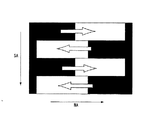
なお、一般的に画像記録装置において、記録中に記録ヘッドは、記録ヘッドを構成する部材(ピエゾ素子、電極、駆動ICなど)の発熱により、温度が変化する。例えば、画像記録に伴う記録ヘッドの昇温により、前記記録ヘッド中のインクは、徐々に粘度が低下する。なお、前記記録ヘッドにおいて、インクの粘度が低下した場合、一度に吐出する各インク滴のインク量が多くなる。従って、記録されるインクドットの径は、大きくなる。記録ヘッドは主走査方向に移動しながらインクを吐出して記録を行う。この移動に伴って温度が変化するため、上述の記録ヘッドにより記録される画像において、図12中に示されるように、主走査軸MAに沿って、1回の走査において記録開始時の記録箇所と記録終了時の記録箇所とでは、光学濃度に差がでてしまう。特に図12中に示されるように、双方向印字をした場合には、上下のバンド間の濃度差が、顕著になり、著しく記録された画像の画質が低下してしまう。
【0005】
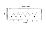
例えば、画像記録装置が、複数走査して画像を記録するとともに、各走査の画像記録において同一の電圧が記録ヘッドに印加された場合、図13中に示されるように光学濃度(OD)が変化する。なお、図13は、印画パターンは60%のハーフトーンで画像が記録された際の光学濃度をグラフにしたものである。図13中に示されるように、1回の走査において記録開始時の記録箇所と記録終了時の記録箇所とでは、光学濃度に差が出てしまっている。具体的には、記録開始時から終了時にかけて、画像の光学濃度(OD)が徐々に大きくなっている。このように、従来の画像記録装置において、記録される画像は、キャリッジの移動方向に沿って、光学濃度が変化し、画質が低下してしまう。
【0006】
なお、上記温度変化は、急激であるため、記録ヘッドに配置されたサーミスター等の温度を検出する素子では、温度変化をリアルタイムで正確に検出することが困難である。
【0007】
近年、記録ヘッドの温度を安定化させることを意図した画像記録装置が考えられている。例えば、このような従来の画像記録装置は、特許文献1中に記載されている。
【0008】
この特許文献1中の画像記録装置は、記録ヘッドにヒーターが接続されており、画像記録中の記録ヘッドの温度を予測し、上記ヒーターにより温度の安定化を図る。
【0009】
また、別の従来の画像記録装置においては、1回の走査全体に渡って、記録ヘッドの駆動電圧を一律に下げることにより、1回の走査においての記録開始時から終了時にかけて記録された画像の光学濃度のむらを防止している。
【0010】
また、さらに別の従来の画像記録装置においては、画像記録前にこれから記録しようとする画像データを取得し、前記画像データの各位置の階調値に応じて、駆動電圧を下げることにより、上記光学濃度のむらを防止している。
【0011】
【特許文献1】
特開平5−54890号公報(第2−25頁、 第5図)
【0012】
【発明が解決しようとする課題】
上記特許文献1の画像記録装置は、記録ヘッドの温度をヒーターにより安定化させるため、記録ヘッドの温度上昇により生じる光学濃度むらを防止することは困難である。
【0013】
また、上記別の従来の画像記録装置は、1回の走査において一律に駆動電圧をさげるため、過補正或いは補正不足により、光学濃度むらの発生する虞がある。
【0014】
また、上記さらに別の従来の画像記録装置は、画像データに応じて電圧を下げるため、補正の過不足は防止されているが、事前の画像データの取得により画像記録のスループットが低下してしまう虞を有している。
【0015】
上記課題を鑑みて、本発明の目的は、画像記録のスループットを下げることなく、光学濃度むらの発生を減少させる又は防止する画像記録装置並びに画像記録方法を提供することである。
【0016】
【課題を解決するための手段】
本発明の画像記録装置は、上記課題を鑑みて以下の構成を有している。
【0017】
本発明の一態様の画像記録装置は、印加された吐出エネルギーに応じてインクを吐出する記録ヘッドと、前記記録ヘッドを保持するキャリッジと、前記キャリッジと記録媒体とを相対的に移動させる走査手段と、を有している。この画像記録装置は、前記キャリッジの相対移動中に前記記録ヘッドからインクを吐出することにより、前記記録媒体に画像を記録する。さらにこの画像記録装置は、前記記録媒体に対するキャリッジの相対移動距離を計測する移動距離計測手段と、前記記録ヘッドから吐出されたインク滴数を計測するインク滴計測手段と、前記キャリッジが前記記録媒体に対して相対的に所定距離移動した際に、前記移動距離計測手段によって計測された記録媒体に対するキャリッジの相対移動距離と、前記所定距離の移動の間に前記記録ヘッドから吐出されたインク滴数とから、記録印画デューティを算出し、前記記録印画デューティの値に応じて記録ヘッドに対して印加する吐出エネルギー量を制御する制御手段とを有している。
【0018】
また、本発明の一態様の画像記録方法は、記録媒体に対して、記録ヘッドを保持する前記キャリッジを相対的に移動させ、前記移動中に前記記録ヘッドに対して吐出エネルギーを印加することによりインクを吐出させ、前記記録媒体に対して画像を記録する。この記録方法において、前記記録媒体に対する前記キャリッジの相対移動距離を計測するとともに、前記記録ヘッドから吐出されたインク滴数を計測する。また、この記録方法は、前記キャリッジが前記記録媒体に対して相対的に所定距離移動した際に、前記相対移動距離と、前記所定距離の移動の間に前記記録ヘッドから吐出されたインク滴数とから、記録印画デューティを算出し、前記記録印画デューティの値に応じて記録ヘッドに対して印加する吐出エネルギー量を制御する。
【0019】
【発明の実施の形態】
以下、図面を参照しながら本発明の実施の形態について説明する。
【0020】
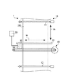
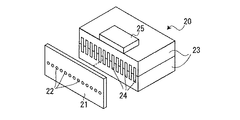
まず、本発明に従った1つの実施の形態について図1並びに図2を用いて説明する。図1は、本実施の形態の画像記録装置を示す概略図である。図2は、図1中の記録ヘッドを示す概略的な分解斜視図である。
【0021】
(構成)
本実施の形態の画像記録装置1は、記録媒体200に対して、インクを吐出して画像を記録する。画像記録装置1は、記録媒体搬送機構10と、記録ヘッド20と、キャリッジ30と、リニアエンコーダ31と、キャリッジ駆動機構40と、制御部50とを有している。
【0022】
記録媒体搬送機構10は、搬送ローラ11、12とを有している。記録媒体搬送機構10は、搬送ローラ11、12とを協働させて、記録媒体200を所定の方向に搬送する。記録媒体200は、図1中の上方から下方に向かって搬送される。
【0023】
記録ヘッド20は、図示しないインク供給源に接続されており、記録媒体200にインクを吐出するインク吐出手段である。この記録ヘッド20は、図2中に示されるように、ノズルプレート21と、圧電素子23とを有している。このノズルプレート21には、インクの吐出口(ノズル)22が複数設けられている。圧電素子23は、2枚が重ねられ互いの接合部に、インク流路の一部である複数のチャンネル24が形成されている。圧電素子23には、各チャンネル24に吐出口22が配置されるように、ノズルプレート21が固定されている。この記録ヘッド20は、制御部50と接続されており、圧電素子23に制御部50からの駆動電圧が印加された際に、各チャンネル24を変形させ、吐出口22からインクを吐出する。なお、この記録ヘッド20は、印加される駆動電圧が高くなるにつれて、吐出するインク量が増える。従って、記録ヘッド20は、駆動電圧が高くなるにつれ、濃く画像を記録する。また、この記録ヘッド20には、この記録ヘッドの温度を検出するための温度検出手段であるヘッドサーミスター25が取り付けられている。このヘッドサーミスターは、制御部50に接続されており、検出結果を制御部50に送る。
【0024】
キャリッジ30は、記録ヘッド20を保持する保持手段であり、キャリッジ駆動機構40により移動可能に支持されている。リニアエンコーダ31は、キャリッジ30の移動距離を計測する移動距離計測手段である。このリニアエンコーダ31は、主走査軸に沿って配置されており、キャリッジ駆動機構40により駆動されるキャリッジ30の主走査軸に沿った移動距離を計測する。またこのリニアエンコーダ31は、制御部50に接続されており、計測結果を制御部50に送る。
【0025】
キャリッジ駆動機構40は、記録媒体200の搬送方向(副走査軸)に対して直交する方向(主走査軸)にキャリッジ30を移動させる。従って、キャリッジ駆動機構40は、キャリッジ30を介して記録ヘッド20を移動させ得る。なお、図1中において、前記副走査軸は、参照符号SAで指摘している矢印に沿った軸心であり、前記主走査軸は、参照符号MAで指摘している矢印に沿った軸心である。なお、前記副走査方向は、記録媒体の幅方向と略一致している。
【0026】
なお、記録媒体搬送機構10とキャリッジ駆動機構40とは、協働して、記録媒体200に対してキャリッジ30を相対的に移動させる走査手段である。
【0027】
制御部50は、記録ヘッド20、記録媒体搬送機構10、及びキャリッジ駆動機構40に接続されており、記録ヘッド20並びに上記走査手段の動作を制御する制御装置である。また、制御部50は、後述するが、記録ヘッド20の印画デューティ(単位時間若しくは単位面積当たりのインク吐出回数)を補正する。
【0028】
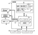
以下に、図3を参照して制御部50をより詳しく説明する。制御部50は、メモリ60と、CPU70と、駆動制御ユニット51とを有している。
【0029】
まず、CPU70について説明する。CPU70は、制御部50の制御を司る制御手段である。このCPU70は、メモリ60と接続されており、メモリ60に対してデータの読み出し並びに書き込みが可能に構成されている。また、このCPU70は、駆動制御ユニット51と接続されており、記録ヘッド20並びに前記走査手段への駆動命令を駆動制御ユニット51に送出する。
【0030】
さらに、このCPU70は、ドットカウンタ71と、演算部72とを有している。
ドットカウンタ71は、記録ヘッド20に対して発行する駆動命令を取得し、この駆動命令に基づいて記録ヘッド20によるインク滴の吐出数を計測するインク滴計測手段である。
【0031】
演算部72は、後述する記録ヘッドの印画デューティを補正する際の演算を行う演算ユニットである。
【0032】
駆動制御ユニット51は、記録媒体搬送機構10、記録ヘッド20、及びキャリッジ駆動機構40と接続されており、CPU70からの命令に従って、これらの動作を制御する。駆動制御ユニット51は、特に、記録ヘッド20に対してインクの吐出に必要な吐出エネルギーを印加する。本実施の形態においては、駆動制御ユニット51は、記録ヘッド20に対して駆動電圧を印加する。
【0033】
メモリ60は、データを格納するデータ格納手段であり、後述する温度―電圧補正テーブル61と温度−印画デューティ補正テーブル62とを有している。また、メモリ60には、記録ヘッド20の吐出口数(ノズル数)等の基本情報が格納されている。
【0034】
(動作)
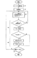
続いて、上記構成の画像記録装置1の動作について説明する。なお、一般的に画像記録において、記録された画像の光学濃度は、吐出されたインク滴の大きさと、印画デューティとに比例して、濃くなる。従って、本実施の形態の画像記録装置1は、均一な光学濃度で画像を記録するために、記録ヘッドの温度が上昇した際に、インク滴の大きさを抑えるように補正(出力補正)を行う。即ち、この画像記録装置1は、出力補正を行いつつ画像を記録する。この画像記録動作を、図4乃至7を参照して以下でより詳しく説明する。この画像記録動作は、図7中に示されるような流れで行われ、以下に示す各工程を行う。
【0035】
(駆動電圧設定工程S1)
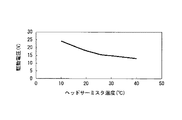
画像記録装置1は、所望の光学濃度で記録が開始し得るように、初期設定が行われる。なお、光学濃度に影響を及ぼすインク滴の大きさは、記録ヘッド20の温度TE、並びに記録ヘッド20の駆動電圧に応じて変化する。このため、駆動電圧設定工程S1では、記録ヘッド20の温度(記録開始前に測定された温度)に基づいて、記録開始時の記録ヘッド20の駆動電圧(開始駆動電圧)を設定する。
【0036】
上記設定のために、まず、記録開始前の記録ヘッド20の温度TEをヘッドサーミスター25により取得する。
【0037】
続いて、温度TEに基づいて、前記開始駆動電圧が決定される。本願の発明者は、実験データにより、所定の光学濃度で記録を行うことが出来る駆動電圧と記録ヘッド20の温度との関係を導きだした。上記関係は、図4中に示されるグラフで表すことが出来る。
【0038】
なお、この図4のグラフは、図5に示される温度−電圧補正テーブル61に基づいて表されたものである。この温度−電圧補正テーブル61は、記録ヘッド20の温度毎に対応する駆動電圧を、実験を繰り返した結果を導き出した算出式からなるものである。この温度−電圧補正テーブル61は、メモリ60中に格納されている。このため、制御部50は、上記ヘッドサーミスター25が計測した温度により、温度−電圧補正テーブル61から対応する駆動電圧を選定し、記録開始駆動電圧に設定する。
この駆動電圧の設定が完了した後、続いて画像記録工程S2が行われる。
【0039】
(画像記録工程S2)
この画像記録工程S2では、制御部50の命令により、画像記録装置1が記録を開始する。具体的には、CPU70からの駆動命令が駆動制御ユニット51を介して前記走査手段並びに記録ヘッド20に送られる。この命令を受け取った後、キャリッジ30が、前記走査手段により記録媒体に対して相対的な移動を開始するとともに、記録ヘッド20が、上記開始駆動電圧を印加され、インクの吐出を開始する。この記録を開始した後、続いてカウント開始工程S3が行われる。
【0040】
(カウント開始工程S3)
このカウント開始工程S3では、ドットカウンタ71が、記録ヘッド20の吐出したインク滴数のカウントを開始する。これとともに、リニアエンコーダ31が、キャリッジの記録媒体に対する相対移動距離のカウントを開始する。本実施の形態において、画像記録装置1は、シリアルタイプである。このため、キャリッジ30は、主走査軸に沿って移動される。そして、1回の走査が終わる度に、記録媒体搬送機構10が記録媒体200を副走査軸に沿って所定量搬送する。従って、1回の走査においては、キャリッジ30は、主走査軸に沿ってのみに移動する。このため、上記相対移動距離(積算印画長)は、主走査軸に沿った記録開始位置からのキャリッジ30の移動距離である。
【0041】
上述のインク滴数のカウントと、相対移動距離の計測が開始された後、印画デューティ判定工程S4が行われる。
【0042】
(印画デューティ判定工程S4)
この印画デューティ判定工程S4では、画像記録時の印画デューティと、基準となる印画デューティとの比較が行われ、この比較時における記録ヘッドの印画デューティ(記録印画デューティPD)が基準となる印画デューティに対してずれが生じているか判定する。なお、上記基準となる印画デューティは、上記比較の基準とするため、説明のために基準印画デューティGDと呼ぶ。この基準印画デューティGDとは、上記温度TEにおいて、所望の光学濃度で記録できる印画デューティである。従って、温度TEにおいて、基準印画デューティGDを越える印画デューティで記録した場合、記録された画像の光学濃度は、所望の光学濃度より、濃くなってしまう。基準印画デューティGDは、後述の式により算出する。
【0043】
上記比較は、キャリッジ30が所定距離ST移動する度に行われる。言い換えると、上記比較は、相対移動距離Lnが、所定距離STの整数倍であるときに行われる。このため、CPU70は、相対移動距離Lnが所定距離STの整数倍であるか判定する。なお、本実施の形態において、所定距離STは、約1.27cm(約0.5インチ)に設定されており、この設定値毎に上記比較を行えるようになっている。
【0044】
この判定において、相対移動距離Lnが所定距離STの整数倍でない場合、継続してカウント開始工程S3が行われる。
【0045】
また、この判定において、相対移動距離Lnが所定距離STの整数倍であるとき、記録印画デューティPD並びに基準印画デューティGDの算出が行われる。
【0046】
この記録印画デューティPDは、演算部72により求められる。具体的には、まず、演算部72が、記録ヘッド20のノズル数Nn、相対移動距離Ln、及びインク滴数(積算ドット数)Dnを取得する。そして、演算部72は、これらの3つの値を用いて、以下に示す式1により、記録印画デューティPDを求める。
【0047】
PD=Dn/(Ln×Nn)…(式1)
続いて、基準印画デューティGDが求められる。なお、本願の発明者は、実験データにより、以下の式2により、上記基準印画デューティGDが求まることを導き出した。
【0048】
GD=(α×PD2-β×PD+γ×ΔT)/(Ln×Nn)…(式2)
なお、式2において、α:係数1、β:係数2、γ:係数3、ΔT:温度補正係数、である。
【0049】
基準印画デューティGDは、記録ヘッド並びにインクの特性に依存するため、上記係数1乃至3のα、β、γは、これらの特性に応じた補正係数である。ある記録ヘッド並びにインクにおいては(例1)、α=1,γ=33、β=4000に設定される。
【0050】
なお、精度よく基準印画デューティGDを求めるためには、温度関数を考慮する必要がある。上記温度補正係数ΔTは、記録時のインク滴が、記録開始時の記録ヘッド20の温度において大きさを基準として、記録していくにつれてそのおおきさが変化するため、上記変化を補正するための係数である。なお、本願の発明者は、実験データにより、以下の式3により、ある記録ヘッド20の温度(ヘッドサーミスターの温度TE)においての上記温度補正係数ΔTが求まることを導き出した。
【0051】
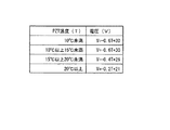
ΔT=ε×TE+η…(式3)
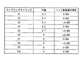
なお、式3において、ε:係数4、η:係数5、である。またこの係数4,5であるε及びηは、本願の発明者が実験データにより導き出した図6の温度−印画デューティ補正テーブル62より、記録印画デューティPDと温度TEに応じて選定される。図6中において、εは、「傾き」として示されており、ηは、「切片」として示されている。例えば、上記例1の記録ヘッド並びにインクを用いた場合において、記録印画デューティPDが、5以上10未満であり、温度TEが26度であった場合、ε=-0.1、η=3.7に設定される。
【0052】
これらの式1乃至3により、記録印画デューティPDと基準印画デューティGDとが求まったら、続いて、これらの比較が演算部72により行われる。
【0053】
この比較において、記録印画デューティPDが、基準印画デューティGD以上だった場合、続いて吐出エネルギー補正工程S5が行われる。なお、この判定により、記録ヘッド20は、基準印画デューティGDより大きい記録印画デューティPDにおいて、記録を行っていることが分かる。
【0054】
また、上記比較において、記録印画デューティPDが、基準印画デューティGDより小さかった場合、相対移動距離Ln及びインク滴数Dnを維持し、続いて終了チェック工程S6が行われる。
【0055】
(吐出エネルギー補正工程S5)
この吐出エネルギー補正工程S5では、記録印画デューティPDが大きくなっている場合には、記録画像の濃度が高くなってしまう。吐出エネルギー補正工程S5では、記録画像の濃度を所望の濃度に合わせるために、CPU70は、駆動制御ユニット51に対して、吐出エネルギーである駆動電圧を所定量下げるように命令する。本実施の形態においては、駆動電圧は、0.08V下げられる。
【0056】
そして、相対移動距離Ln及びインク滴数Dnが0にリセットされる。このリセット後、続いて終了チェック工程S6が行われる。
【0057】
(終了チェック工程S6)
この終了チェック工程において、演算部72は、1回の走査が完了したかチェックする。1回の走査の途中である場合、再びカウント開始工程S3が行われる。即ち、1回の走査の途中である場合、駆動電圧、及び温度TEの値は、維持される。
【0058】
また、1回の走査が完了した場合、インク滴数Dn、相対移動距離Ln、温度TEを0にリセットし、次の走査を行う。
【0059】
このようにして、本実施の形態の画像記録装置1は、画像の記録を行う。
上述のように、本実施の形態の前記制御手段であるCPU70は、前記相対移動距離Lnと、インク滴数Dnとから記録印画デューティPDを算出し、この記録印画デューティPDに応じて記録ヘッドに印加する吐出エネルギー量を制御する。従って、本実施の形態の画像記録装置は、画像記録時に急激に記録ヘッドの温度が変化する場合においても、吐出エネルギー量を制御することにより、リアルタイムに温度計測を行うことなく、記録画像の光学濃度の上昇を防止し、光学濃度むらの発生を減少又は防止することが出来る。なお、前記記録印画デューティPDは、記録する画像データを解析する場合に比べて、短時間で算出し得る。従って、本実施の形態の画像記録装置1は、画像記録のスループットを低下させることなく、光学濃度むらの発生を減少又は防止し得る。
【0060】
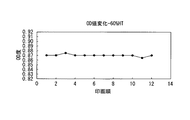
なお、上述のように吐出エネルギー量を補正した場合、印画パターン60%のハーフトーンで画像が記録された際の光学濃度をグラフ(図8参照)は、複数回の走査により画像を記録した場合においても、常に略一定の光学濃度で画像を記録し得る。従って、本実施の形態の画像記録装置1は、濃度むらを防止し、高画質に画像の記録を行い得る。
【0061】
また、CPU70は、基準印画デューティGDに対して記録印画デューティPDを比較し、吐出エネルギー量を制御し得る。従って、本実施の形態の画像記録装置1は、基準印画デューティGDに対するずれを比較し得る。従って、本実施の形態の画像記録装置1は、より確実に濃度むらを防止し得る。
【0062】
また、本実施の形態の画像記録装置1は、記録印画デューティPDが、基準印画デューティGD以上である場合、吐出エネルギー量を小さくする。記録ヘッド20は、印加されるエネルギーが減少した場合、画像記録の際の印画デューティが低くなる。従って、本実施の形態の画像記録装置は、記録ヘッドの温度上昇等により、記録時の光学濃度が上昇した場合においても、上記上昇を補正することが出来、濃度むらの発生を防止し得る。
【0063】
また、本実施の形態の画像記録装置1は、演算部71が、基準印画デューティGDに対して記録印画デューティPDの値が小さいと判定した場合、前記印加する吐出エネルギー量を、比較前の状態に維持する。これにより、本実施の形態の画像記録装置1は、記録印画デューティPDが、基準印画デューティGDより小さい場合、吐出エネルギー量を維持し、続いて補正が行われた際に過補正又は補正不足になること防止し得る。
【0064】
また、演算部72は、画像記録時において、前記キャリッジが前記記録媒体に対して相対的に所定移動距離移動した毎に、上記比較を行い得る。これにより、本実施の形態の画像記録装置は、複数回の印画デューティの比較を行うことができ、より精度よく印画デューティの補正を行い得る。
【0065】
また、CPU70は、演算部71により記録印画デューティPDの値が基準印画デューティGDより大きいと判定された場合、前記計測したインク滴数をリセットする。これにより、補正後に再び設定をリセットすることが可能である。従って、複数回の前記印画デューティの比較においても、補正時の比較に用いたデータに左右されることなく正確に各比較を行うことが可能である。
【0066】
また、本実施の形態の画像記録装置1は、記録ヘッド20の温度を検出する温度検出手段であるヘッドサーミスター25を有しており、これにより検出された温度TEに基づいて、基準印画デューティGDを算出する。
【0067】
上記構成により、記録ヘッドの温度に基づいて、基準印画デューティGDを算出し得る。従って、複数回検査を行う場合において、基準印画デューティGDを求める際に各回毎に記録ヘッドの温度が異なる場合においても、確実に基準印画デューティGDを求めることが可能である。
【0068】
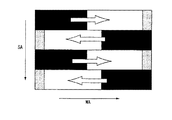
また、本実施の形態において、画像記録装置1は、インク吐出動作に伴った記録ヘッド20の温度上昇により、インクの粘度が低下した場合において、吐出エネルギーを下げる制御についてのみ説明した。しかしながら、本実施の形態の画像記録装置1は、記録ヘッド20が温度低下し、インクの粘度が増大した場合において、吐出エネルギーを上昇させることも可能である。例えば、図9中に示されるような画像データは、各走査において、印字を行わない空白データ部分がある。この画像データを画像記録装置が記録する場合、空白データ部分により、記録ヘッド20の温度が低下する場合がある。この場合において、基準印画デューティGDと記録印画デューティPDとを比較した際に、所定の範囲より記録印画デューティPDが小さくなることがある。この場合、画像記録装置1は、印加する吐出エネルギー量を増大させるように制御する。このような制御は、例えば、図11中に示すように、印加する吐出エネルギー量を、増大と減少とを組み合わせて行うことも可能である。このように制御した場合、画像記録装置1は、記録ヘッド20の温度が低下した場合においても、高画質で画像を記録し得る。
【0069】
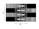
また、本実施の形態の画像記録装置において、ドットカウンタ71は、全ての吐出したインクドットを積算したが、図10中において灰色で示すような記録ヘッドの温度上昇に影響しないような低い解像度の領域を記録した際のインクドットを積算しないことも可能である。
【0070】
なお、本実施の形態において、相対移動距離Lnは、リニアエンコーダにより計測したが、他の公知の測定機器を用いることも可能であるし、キャリッジの移動速度並びに移動時間に基づいて、相対移動距離Lnを算出することも可能である。
【0071】
また、本実施形態において、駆動電圧は、0.08V毎に調整されているが、この吐出エネルギーを調整する量は、用いられる記録ヘッド並びにインクに対応して変化するため、上記値には限定されず、任意に変更し得る。
【0072】
また、本実施の形態において、吐出エネルギーは、駆動電圧であったが、記録ヘッドの特性に合わせて、パルス幅、周波数などの他のエネルギー量に置き換えられることは言うまでもない。
【0073】
また、本実施の形態の画像記録装置1は、キャリッジ自体が走査するシリアルタイプであるが、フルラインタイプにすることも可能である。この場合、相対移動距離Lnは、キャリッジに対する記録媒体200の搬送量になる。
【0074】
これまで、いくつかの実施の形態について図面を参照しながら具体的に説明したが、本発明は、上述した実施の形態に限定されるものではなく、その要旨を逸脱しない範囲で行なわれるすべての実施を含む。
【0075】
【発明の効果】
上記課題を鑑みて、本発明の目的は、画像記録のスループットを下げることなく、光学濃度むらの発生を減少させる又は防止する画像記録装置並びに画像記録方法を提供することである。
【図面の簡単な説明】
【図1】 図1は、本発明の1つの実施の形態に従った画像記録装置を示す概略図である。
【図2】 図2は、図1中の画像記録装置の記録ヘッドを示す概略的な分解斜視図である。
【図3】 図3は、図1中の制御部を示す概略的なブロック図である。
【図4】 図4は、正常な印画デューティで記録を行うことが出来る駆動電圧と記録ヘッド20の温度との関係を示すグラフである。
【図5】 図5は、温度−電圧補正テーブルを示す図である。
【図6】 図6は、温度−印画デューティ補正テーブルを示す図である。
【図7】 図7は、画像記録装置1の動作を示すフロー図である。
【図8】 図8は、図1中の画像記録装置の記録結果の光学濃度を示すグラフである。
【図9】 図9は、1つの変形例の画像記録装置により記録される画像データを示す図である。
【図10】 図10は、他の変形例の画像記録装置により記録される画像データを示す図である。
【図11】 図11は、図9中の画像を記録した際の上記1つの変形例の画像記録装置の駆動電圧の変化を示す図である。
【図12】 図12は、従来の画像記録装置により記録結果を示す図である。
【図13】 図13は、従来の画像記録装置の記録結果の光学濃度を示すグラフである。
【符号の説明】
MA…主走査軸、SA…副走査軸、S1…駆動電圧設定工程、S2…画像記録工程、S3…カウント開始工程、S4…印画デューティ判定工程、GD…基準印画デューティ、ST…所定距離、Ln…相対移動距離、PD…記録印画デューティ、S5…吐出エネルギー補正工程、S6…終了チェック工程、1…画像記録装置、10…記録媒体搬送機構、11,12…搬送ローラ、20…記録ヘッド、21…ノズルプレート、22…吐出口、23…圧電素子、24…チャンネル、25…ヘッドサーミスター、30…キャリッジ、31…リニアエンコーダ、40…キャリッジ駆動機構、50…制御部、51…駆動制御ユニット、60…メモリ、60…印画パターン、61…温度補正テーブル、62…電圧補正テーブル、70…CPU、71…ドットカウンタ、72…演算部、200…記録媒体[0001]
BACKGROUND OF THE INVENTION
The present invention relates to an image recording apparatus and an image recording method for recording an image on a recording medium.
[0002]
[Prior art]
An image recording apparatus such as an ink jet printer records an image by attaching ink to a recording medium such as paper. The image recording apparatus includes a recording head for ejecting ink onto the recording medium, a carriage that holds the recording head, a recording medium conveyance mechanism that conveys the recording medium, and a recording medium that is formed by the recording medium conveyance mechanism. Carriage driving means for moving the recording head to an axis (main scanning direction MA) orthogonal to an axis (sub-scanning axis SA) along the transport direction.
[0003]
In such a conventional image recording apparatus, the carriage is driven along the main scanning axis MA, and ink droplets are applied to the recording medium on the recording head that moves in accordance with the driving. As a result, the image recording apparatus operates to land ink droplets at substantially equal pitches along the main scanning axis MA and to record an image corresponding to the width of the recording head. The image recording apparatus records the entire desired image on the recording medium by repeating the above operation on the recording medium sequentially conveyed along the sub-scanning axis SA.
[0004]
In general, in an image recording apparatus, during recording, the temperature of the recording head changes due to heat generated by members (piezo elements, electrodes, driving ICs, etc.) constituting the recording head. For example, the viscosity of the ink in the recording head gradually decreases due to the temperature rise of the recording head accompanying image recording. In the recording head, when the viscosity of the ink is reduced, the ink amount of each ink droplet ejected at a time is increased. Accordingly, the diameter of the ink dot to be recorded becomes large. The recording head performs recording by ejecting ink while moving in the main scanning direction. Since the temperature changes with this movement, in the image recorded by the recording head described above, as shown in FIG. 12, the recording position at the start of recording in one scan along the main scanning axis MA. There is a difference in optical density between the recording position and the recording position at the end of recording. In particular, as shown in FIG. 12, when bi-directional printing is performed, the density difference between the upper and lower bands becomes significant, and the image quality of the recorded image is significantly reduced.
[0005]
For example, when the image recording apparatus scans a plurality of images to record an image, and the same voltage is applied to the recording head in each scanning image recording, the optical density (OD) changes as shown in FIG. To do. FIG. 13 is a graph showing the optical density when an image is recorded with a halftone of 60% in the print pattern. As shown in FIG. 13, there is a difference in optical density between the recording location at the start of recording and the recording location at the end of recording in one scan. Specifically, the optical density (OD) of the image gradually increases from the start to the end of recording. As described above, in the conventional image recording apparatus, the optical density of the image to be recorded changes along the moving direction of the carriage, and the image quality deteriorates.
[0006]
Since the temperature change is abrupt, it is difficult to accurately detect the temperature change in real time with an element such as a thermistor arranged in the recording head.
[0007]
In recent years, an image recording apparatus intended to stabilize the temperature of the recording head has been considered. For example, such a conventional image recording apparatus is described in
[0008]
In the image recording apparatus in
[0009]
In another conventional image recording apparatus, an image recorded from the start to the end of recording in one scan is obtained by uniformly reducing the drive voltage of the recording head over the entire scan. Prevents unevenness in optical density.
[0010]
Further, in another conventional image recording apparatus, the image data to be recorded is acquired before image recording, and the drive voltage is lowered according to the gradation value at each position of the image data. Uneven optical density is prevented.
[0011]
[Patent Document 1]
Japanese Patent Laid-Open No. 5-54890 (page 2-25, FIG. 5)
[0012]
[Problems to be solved by the invention]
Since the image recording apparatus of
[0013]
In addition, the other conventional image recording apparatus uniformly reduces the drive voltage in one scan, and thus there is a risk of uneven optical density due to overcorrection or insufficient correction.
[0014]
In addition, the above-described another conventional image recording apparatus lowers the voltage in accordance with the image data, so that excessive or insufficient correction is prevented, but the image recording throughput decreases due to the acquisition of the image data in advance. I have a fear.
[0015]
In view of the above problems, an object of the present invention is to provide an image recording apparatus and an image recording method that reduce or prevent the occurrence of optical density unevenness without reducing the throughput of image recording.
[0016]
[Means for Solving the Problems]
The image recording apparatus of the present invention has the following configuration in view of the above problems.
[0017]
An image recording apparatus according to an aspect of the present invention includes a recording head that ejects ink according to applied ejection energy, a carriage that holds the recording head, and a scanning unit that relatively moves the carriage and the recording medium. And have. The image recording apparatus records an image on the recording medium by ejecting ink from the recording head during relative movement of the carriage. The image recording apparatus further includes a moving distance measuring unit that measures a relative moving distance of the carriage with respect to the recording medium, an ink droplet measuring unit that measures the number of ink droplets ejected from the recording head, and the carriage includes the recording medium. The relative movement distance of the carriage with respect to the recording medium measured by the movement distance measuring means and the number of ink droplets ejected from the recording head during the movement of the predetermined distance And a control means for calculating the recording print duty and controlling the amount of ejection energy applied to the recording head in accordance with the value of the recording print duty.
[0018]
In the image recording method of one embodiment of the present invention, the carriage that holds the recording head is moved relative to the recording medium, and ejection energy is applied to the recording head during the movement. Ink is ejected to record an image on the recording medium. In this recording method, the relative movement distance of the carriage with respect to the recording medium is measured, and the number of ink droplets ejected from the recording head is measured. In this recording method, when the carriage moves a predetermined distance relative to the recording medium, the relative movement distance and the number of ink droplets ejected from the recording head during the movement of the predetermined distance. From this, the recording printing duty is calculated, and the amount of ejection energy applied to the recording head is controlled according to the value of the recording printing duty.
[0019]
DETAILED DESCRIPTION OF THE INVENTION
Hereinafter, embodiments of the present invention will be described with reference to the drawings.
[0020]
First, an embodiment according to the present invention will be described with reference to FIG. 1 and FIG. FIG. 1 is a schematic diagram showing an image recording apparatus according to the present embodiment. FIG. 2 is a schematic exploded perspective view showing the recording head in FIG.
[0021]
(Constitution)
The
[0022]
The recording
[0023]
The
[0024]
The
[0025]
The
[0026]
The recording
[0027]
The
[0028]
Hereinafter, the
[0029]
First, the
[0030]
Further, the
The dot counter 71 is an ink droplet measuring unit that acquires a drive command issued to the
[0031]
The
[0032]
The
[0033]
The
[0034]
(Operation)
Next, the operation of the
[0035]
(Drive voltage setting step S1)
The
[0036]
For the above setting, first, the temperature TE of the
[0037]
Subsequently, the start drive voltage is determined based on the temperature TE. The inventor of the present application has derived the relationship between the driving voltage at which recording can be performed at a predetermined optical density and the temperature of the
[0038]
The graph of FIG. 4 is expressed based on the temperature-voltage correction table 61 shown in FIG. This temperature-voltage correction table 61 is made up of calculation formulas derived from the results of repeated experiments on the drive voltage corresponding to each temperature of the
After the setting of the drive voltage is completed, an image recording process S2 is subsequently performed.
[0039]
(Image recording step S2)
In the image recording step S2, the
[0040]
(Count start process S3)
In this counting start step S3, the dot counter 71 starts counting the number of ink droplets ejected by the
[0041]
After the above-described counting of the number of ink droplets and measurement of the relative movement distance are started, the printing duty determination step S4 is performed.
[0042]
(Print Duty Determination Step S4)
In this print duty determination step S4, a comparison is made between the print duty at the time of image recording and the reference print duty, and the print duty (recording print duty PD) of the print head at this comparison is used as the reference print duty. On the other hand, it is determined whether or not a deviation occurs. The reference print duty is referred to as a reference print duty GD for the sake of explanation because it is used as a reference for the comparison. The reference print duty GD is a print duty that can be recorded at a desired optical density at the temperature TE. Accordingly, when recording is performed at a temperature TE at a printing duty exceeding the reference printing duty GD, the optical density of the recorded image is higher than the desired optical density. The reference print duty GD is calculated by the formula described later.
[0043]
The comparison is performed every time the
[0044]
In this determination, when the relative movement distance Ln is not an integral multiple of the predetermined distance ST, the count start process S3 is continuously performed.
[0045]
In this determination, when the relative movement distance Ln is an integer multiple of the predetermined distance ST, the recording print duty PD and the reference print duty GD are calculated.
[0046]
The recording print duty PD is obtained by the
[0047]
PD = Dn / (Ln × Nn) (Formula 1)
Subsequently, a reference printing duty GD is obtained. The inventor of the present application has derived that the above-described reference print duty GD is obtained from the
[0048]
GD = (α × PD 2 −β × PD + γ × ΔT) / (Ln × Nn) (Formula 2)
In
[0049]
Since the reference printing duty GD depends on the characteristics of the print head and ink, α, β, and γ in the
[0050]
In order to obtain the reference printing duty GD with high accuracy, it is necessary to consider the temperature function. The temperature correction coefficient ΔT is for correcting the change because the ink droplet at the time of recording changes as the ink droplet is recorded with reference to the size at the temperature of the
[0051]
ΔT = ε × TE + η (Expression 3)
In
[0052]
When the recording print duty PD and the reference print duty GD are obtained by these
[0053]
In this comparison, when the recording print duty PD is equal to or greater than the reference print duty GD, the ejection energy correction step S5 is subsequently performed. By this determination, it can be seen that the
[0054]
In the above comparison, when the recording print duty PD is smaller than the reference print duty GD, the relative movement distance Ln and the number of ink droplets Dn are maintained, and then the end check step S6 is performed.
[0055]
(Discharge energy correction process S5)
In the ejection energy correction step S5, when the recording print duty PD is large, the density of the recorded image is increased. In the ejection energy correction step S5, the
[0056]
Then, the relative movement distance Ln and the ink droplet number Dn are reset to zero. After this reset, an end check step S6 is subsequently performed.
[0057]
(End check process S6)
In this end check step, the
[0058]
When one scan is completed, the number of ink droplets Dn, the relative movement distance Ln, and the temperature TE are reset to 0, and the next scan is performed.
[0059]
In this way, the
As described above, the
[0060]
When the ejection energy amount is corrected as described above, the optical density when the image is recorded with a halftone of the print pattern of 60% (see FIG. 8) is a graph when the image is recorded by a plurality of scans. In this case, an image can always be recorded with a substantially constant optical density. Therefore, the
[0061]
Further, the
[0062]
Further, the
[0063]
Further, in the
[0064]
In addition, the
[0065]
Further, when the calculation unit 71 determines that the value of the recording print duty PD is larger than the reference print duty GD, the
[0066]
Further, the
[0067]
With the above configuration, the reference print duty GD can be calculated based on the temperature of the recording head. Accordingly, in the case where the inspection is performed a plurality of times, the reference print duty GD can be reliably obtained even when the temperature of the recording head is different each time when the reference print duty GD is obtained.
[0068]
Further, in the present embodiment, the
[0069]
Further, in the image recording apparatus of the present embodiment, the dot counter 71 integrated all the ejected ink dots, but has a low resolution that does not affect the temperature rise of the recording head as shown in gray in FIG. It is also possible not to integrate the ink dots when the area is recorded.
[0070]
In this embodiment, the relative movement distance Ln is measured by a linear encoder. However, other known measuring devices can be used, and the relative movement distance can be determined based on the movement speed and movement time of the carriage. It is also possible to calculate Ln.
[0071]
In this embodiment, the drive voltage is adjusted every 0.08 V. However, the amount for adjusting the ejection energy changes corresponding to the recording head and ink used, and thus is limited to the above value. It can be changed arbitrarily.
[0072]
In the present embodiment, the ejection energy is a drive voltage, but it is needless to say that the energy is replaced with other energy amounts such as a pulse width and a frequency in accordance with the characteristics of the recording head.
[0073]
The
[0074]
Although several embodiments have been specifically described so far with reference to the drawings, the present invention is not limited to the above-described embodiments, and all the embodiments performed without departing from the scope of the invention are not limited thereto. Including implementation.
[0075]
【The invention's effect】
In view of the above problems, an object of the present invention is to provide an image recording apparatus and an image recording method that reduce or prevent the occurrence of optical density unevenness without reducing the throughput of image recording.
[Brief description of the drawings]
FIG. 1 is a schematic diagram showing an image recording apparatus according to one embodiment of the present invention.
FIG. 2 is a schematic exploded perspective view showing a recording head of the image recording apparatus in FIG. 1;
FIG. 3 is a schematic block diagram showing a control unit in FIG. 1;
FIG. 4 is a graph showing the relationship between the drive voltage at which recording can be performed with a normal printing duty and the temperature of the
FIG. 5 is a diagram illustrating a temperature-voltage correction table.
FIG. 6 is a diagram illustrating a temperature-printing duty correction table.
FIG. 7 is a flowchart showing the operation of the
FIG. 8 is a graph showing the optical density of the recording result of the image recording apparatus in FIG. 1;
FIG. 9 is a diagram illustrating image data recorded by an image recording apparatus according to one modification.
FIG. 10 is a diagram illustrating image data recorded by an image recording apparatus according to another modification.
FIG. 11 is a diagram illustrating a change in driving voltage of the image recording apparatus according to the one modification when the image in FIG. 9 is recorded.
FIG. 12 is a diagram showing a result of recording by a conventional image recording apparatus.
FIG. 13 is a graph showing the optical density of a recording result of a conventional image recording apparatus.
[Explanation of symbols]
MA: main scanning axis, SA: sub-scanning axis, S1: drive voltage setting step, S2: image recording step, S3: count start step, S4: printing duty determination step, GD: reference printing duty, ST: predetermined distance, Ln ... relative movement distance, PD ... recording printing duty, S5 ... discharge energy correction process, S6 ... end check process, 1 ... image recording device, 10 ... recording medium transport mechanism, 11, 12 ... transport roller, 20 ... recording head, 21 DESCRIPTION OF SYMBOLS ... Nozzle plate, 22 ... Discharge port, 23 ... Piezoelectric element, 24 ... Channel, 25 ... Head thermistor, 30 ... Carriage, 31 ... Linear encoder, 40 ... Carriage drive mechanism, 50 ... Control part, 51 ... Drive control unit, 60 ... Memory, 60 ... Print pattern, 61 ... Temperature correction table, 62 ... Voltage correction table, 70 ... CPU, 71 ... Dot Counter, 72 ... arithmetic unit, 200 ... recording medium
Claims (11)
前記記録ヘッドを保持するキャリッジと、
前記キャリッジと記録媒体とを相対的に移動させる走査手段と、
を有し、
前記キャリッジの相対移動中に前記記録ヘッドからインクを吐出することにより、前記記録媒体に画像を記録する画像記録装置において、
前記記録媒体に対するキャリッジの相対移動距離を計測する移動距離計測手段と、
前記記録ヘッドから吐出されたインク滴数を計測するインク滴計測手段と、
前記キャリッジが前記記録媒体に対して相対的に所定距離移動した際に、前記移動距離計測手段によって計測された記録媒体に対するキャリッジの相対移動距離と、前記所定距離の移動の間に前記記録ヘッドから吐出されたインク滴数とから、記録印画デューティを算出し、前記記録印画デューティの値に応じて記録ヘッドに対して印加する吐出エネルギー量を制御する制御手段と、
を有している画像記録装置。A recording head that ejects ink according to the applied ejection energy;
A carriage for holding the recording head;
Scanning means for relatively moving the carriage and the recording medium;
Have
In an image recording apparatus for recording an image on the recording medium by ejecting ink from the recording head during relative movement of the carriage,
A moving distance measuring means for measuring a relative moving distance of the carriage with respect to the recording medium;
Ink droplet measuring means for measuring the number of ink droplets ejected from the recording head;
When the carriage moves by a predetermined distance relative to the recording medium, the relative movement distance of the carriage relative to the recording medium measured by the moving distance measuring unit and the movement of the predetermined distance from the recording head. A control means for calculating a recording printing duty from the number of ejected ink droplets and controlling an amount of ejection energy applied to the recording head according to the value of the recording printing duty;
An image recording apparatus.
前記制御手段は、前記演算部による前記比較結果に応じて、前記印加する吐出エネルギー量を制御する請求項1に記載の画像記録装置。The control means includes a reference printing duty, and includes a calculation unit that compares the reference printing duty with a value of the recording printing duty.
The image recording apparatus according to claim 1, wherein the control unit controls the amount of ejection energy to be applied according to the comparison result by the calculation unit.
前記制御手段は、前記温度検出手段の検出結果に基づいて、前記基準印画デューティを算出する請求項2に記載の画像記録装置。Further comprising temperature detecting means for detecting the temperature of the recording head;
The image recording apparatus according to claim 2, wherein the control unit calculates the reference print duty based on a detection result of the temperature detection unit.
前記記録媒体に対する前記キャリッジの相対移動距離を計測するとともに、前記記録ヘッドから吐出されたインク滴数を計測し、
前記キャリッジが前記記録媒体に対して相対的に所定距離移動した際に、前記相対移動距離と、前記所定距離の移動の間に前記記録ヘッドから吐出されたインク滴数とから、記録印画デューティを算出し、前記記録印画デューティの値に応じて記録ヘッドに対して印加する吐出エネルギー量を制御する画像記録方法。The carriage for holding the recording head is moved relative to the recording medium, and ink is ejected to the recording head by applying ejection energy to the recording head during the movement. In an image recording method for recording an image,
Measuring the relative movement distance of the carriage with respect to the recording medium, and measuring the number of ink droplets ejected from the recording head;
When the carriage moves a predetermined distance relative to the recording medium, a recording print duty is calculated from the relative movement distance and the number of ink droplets ejected from the recording head during the movement of the predetermined distance. An image recording method for calculating and controlling an ejection energy amount applied to a recording head in accordance with a value of the recording printing duty.
基準印画デューティを取得し、前記基準印画デューティと前記記録印画デューティとを比較することにより行われる請求項9に記載の画像記録方法。The control of the discharge energy amount is as follows:
The image recording method according to claim 9, wherein the image recording method is performed by obtaining a reference printing duty and comparing the reference printing duty with the recording printing duty.
Priority Applications (2)
| Application Number | Priority Date | Filing Date | Title |
|---|---|---|---|
| JP2003201268A JP4358564B2 (en) | 2003-07-24 | 2003-07-24 | Image recording apparatus and image recording method |
| US10/897,343 US7188920B2 (en) | 2003-07-24 | 2004-07-21 | Image recording apparatus and image recording method |
Applications Claiming Priority (1)
| Application Number | Priority Date | Filing Date | Title |
|---|---|---|---|
| JP2003201268A JP4358564B2 (en) | 2003-07-24 | 2003-07-24 | Image recording apparatus and image recording method |
Publications (2)
| Publication Number | Publication Date |
|---|---|
| JP2005041037A JP2005041037A (en) | 2005-02-17 |
| JP4358564B2 true JP4358564B2 (en) | 2009-11-04 |
Family
ID=34074498
Family Applications (1)
| Application Number | Title | Priority Date | Filing Date |
|---|---|---|---|
| JP2003201268A Expired - Fee Related JP4358564B2 (en) | 2003-07-24 | 2003-07-24 | Image recording apparatus and image recording method |
Country Status (2)
| Country | Link |
|---|---|
| US (1) | US7188920B2 (en) |
| JP (1) | JP4358564B2 (en) |
Families Citing this family (2)
| Publication number | Priority date | Publication date | Assignee | Title |
|---|---|---|---|---|
| US7402719B2 (en) * | 2002-06-13 | 2008-07-22 | Velocys | Catalytic oxidative dehydrogenation, and microchannel reactors for catalytic oxidative dehydrogenation |
| JP7035887B2 (en) * | 2018-07-31 | 2022-03-15 | ブラザー工業株式会社 | Image recording device |
Family Cites Families (16)
| Publication number | Priority date | Publication date | Assignee | Title |
|---|---|---|---|---|
| KR930011862B1 (en) * | 1989-09-18 | 1993-12-21 | 캐논 가부시끼가이샤 | Inkjet recording device and temperature control method thereof |
| JPH04250060A (en) * | 1990-12-26 | 1992-09-04 | Fuji Xerox Co Ltd | Temperature control device for ink jet recording device |
| JP2974487B2 (en) | 1991-03-20 | 1999-11-10 | キヤノン株式会社 | Recording device |
| US5515087A (en) * | 1993-12-02 | 1996-05-07 | Hewlett-Packard Company | Remaining battery capacity determination method and apparatus |
| JPH07214824A (en) * | 1994-02-08 | 1995-08-15 | Mita Ind Co Ltd | Image recording device |
| JP3131104B2 (en) * | 1994-11-07 | 2001-01-31 | キヤノンアプテックス株式会社 | Printer device |
| JPH08156258A (en) * | 1994-12-08 | 1996-06-18 | Copyer Co Ltd | Image forming apparatus |
| JP3311186B2 (en) * | 1995-02-14 | 2002-08-05 | キヤノン株式会社 | Recording apparatus and driving method in the apparatus |
| JPH0911504A (en) * | 1995-06-30 | 1997-01-14 | Canon Inc | Inkjet recording method, recording apparatus, and information processing system |
| JP3323778B2 (en) * | 1997-06-19 | 2002-09-09 | キヤノン株式会社 | Recording method and apparatus |
| JP4913939B2 (en) * | 2000-09-29 | 2012-04-11 | キヤノン株式会社 | Inkjet recording apparatus and inkjet recording method |
| JP3774640B2 (en) * | 2001-05-17 | 2006-05-17 | キヤノン株式会社 | Inkjet recording apparatus and inkjet recording method |
| JP2003127353A (en) * | 2001-08-10 | 2003-05-08 | Canon Inc | Inkjet recording device |
| US6766121B2 (en) * | 2001-11-26 | 2004-07-20 | Oki Data Corporation | Image forming apparatus that periodically discharges waste toner and method of operation thereof |
| JP2003182056A (en) * | 2001-12-18 | 2003-07-03 | Sii Printek Inc | Inkjet recorder |
| US7175249B2 (en) * | 2003-06-06 | 2007-02-13 | Canon Kabushiki Kaisha | Recording apparatus and electronic apparatus |
-
2003
- 2003-07-24 JP JP2003201268A patent/JP4358564B2/en not_active Expired - Fee Related
-
2004
- 2004-07-21 US US10/897,343 patent/US7188920B2/en not_active Expired - Fee Related
Also Published As
| Publication number | Publication date |
|---|---|
| US20050018002A1 (en) | 2005-01-27 |
| US7188920B2 (en) | 2007-03-13 |
| JP2005041037A (en) | 2005-02-17 |
Similar Documents
| Publication | Publication Date | Title |
|---|---|---|
| US8931875B2 (en) | Inkjet printing apparatus and inkjet printing method | |
| US20100156977A1 (en) | Ink jet printing apparatus and printing method | |
| JP5201969B2 (en) | Ink jet recording apparatus and recording method in ink jet recording apparatus | |
| US20130235104A1 (en) | Inkjet printing apparatus and driving method | |
| US7380897B2 (en) | Method and apparatus for calibrating a printhead | |
| US20100079514A1 (en) | Liquid supply device, image forming device, and computer readable medium | |
| US8439471B2 (en) | Ink jet recording apparatus, and method for controlling recording head temperature | |
| US10994536B2 (en) | Image recording apparatus | |
| US9981468B2 (en) | Ink jet printing apparatus and method for controlling inkjet printing apparatus | |
| JP5901239B2 (en) | Inkjet recording apparatus and inkjet recording method | |
| US7264326B2 (en) | Inkjet printer | |
| US9180660B2 (en) | Ink jet recording apparatus | |
| JP2021172074A (en) | Image formation apparatus and conveyance device | |
| JP4358564B2 (en) | Image recording apparatus and image recording method | |
| US8474941B2 (en) | Inkjet printing apparatus and inkjet printing method | |
| JPH0418363A (en) | image forming device | |
| JPH0418356A (en) | Image formation device | |
| JP7131167B2 (en) | Droplet ejection device | |
| US20080297552A1 (en) | Ink jet printing apparatus and ink jet printing method | |
| JP5603703B2 (en) | Recording apparatus and recording position adjusting method thereof | |
| JP2013006337A (en) | Recording apparatus and method of controlling the same | |
| US9738069B2 (en) | Inkjet printing apparatus and inkjet printing method | |
| JP2004122533A (en) | Inkjet recording device and inkjet recording method | |
| JP2008162067A (en) | Inkjet recording apparatus and inkjet recording method | |
| US10647112B2 (en) | Liquid droplet discharging apparatus having movement correction |
Legal Events
| Date | Code | Title | Description |
|---|---|---|---|
| A621 | Written request for application examination |
Free format text: JAPANESE INTERMEDIATE CODE: A621 Effective date: 20060714 |
|
| A977 | Report on retrieval |
Free format text: JAPANESE INTERMEDIATE CODE: A971007 Effective date: 20090629 |
|
| TRDD | Decision of grant or rejection written | ||
| A01 | Written decision to grant a patent or to grant a registration (utility model) |
Free format text: JAPANESE INTERMEDIATE CODE: A01 Effective date: 20090714 |
|
| A01 | Written decision to grant a patent or to grant a registration (utility model) |
Free format text: JAPANESE INTERMEDIATE CODE: A01 |
|
| A61 | First payment of annual fees (during grant procedure) |
Free format text: JAPANESE INTERMEDIATE CODE: A61 Effective date: 20090806 |
|
| FPAY | Renewal fee payment (event date is renewal date of database) |
Free format text: PAYMENT UNTIL: 20120814 Year of fee payment: 3 |
|
| FPAY | Renewal fee payment (event date is renewal date of database) |
Free format text: PAYMENT UNTIL: 20120814 Year of fee payment: 3 |
|
| FPAY | Renewal fee payment (event date is renewal date of database) |
Free format text: PAYMENT UNTIL: 20120814 Year of fee payment: 3 |
|
| S111 | Request for change of ownership or part of ownership |
Free format text: JAPANESE INTERMEDIATE CODE: R313114 |
|
| S111 | Request for change of ownership or part of ownership |
Free format text: JAPANESE INTERMEDIATE CODE: R313117 |
|
| FPAY | Renewal fee payment (event date is renewal date of database) |
Free format text: PAYMENT UNTIL: 20120814 Year of fee payment: 3 |
|
| R350 | Written notification of registration of transfer |
Free format text: JAPANESE INTERMEDIATE CODE: R350 |
|
| FPAY | Renewal fee payment (event date is renewal date of database) |
Free format text: PAYMENT UNTIL: 20120814 Year of fee payment: 3 |
|
| S111 | Request for change of ownership or part of ownership |
Free format text: JAPANESE INTERMEDIATE CODE: R313115 |
|
| FPAY | Renewal fee payment (event date is renewal date of database) |
Free format text: PAYMENT UNTIL: 20120814 Year of fee payment: 3 |
|
| R350 | Written notification of registration of transfer |
Free format text: JAPANESE INTERMEDIATE CODE: R350 |
|
| FPAY | Renewal fee payment (event date is renewal date of database) |
Free format text: PAYMENT UNTIL: 20120814 Year of fee payment: 3 |
|
| FPAY | Renewal fee payment (event date is renewal date of database) |
Free format text: PAYMENT UNTIL: 20130814 Year of fee payment: 4 |
|
| R250 | Receipt of annual fees |
Free format text: JAPANESE INTERMEDIATE CODE: R250 |
|
| R250 | Receipt of annual fees |
Free format text: JAPANESE INTERMEDIATE CODE: R250 |
|
| R250 | Receipt of annual fees |
Free format text: JAPANESE INTERMEDIATE CODE: R250 |
|
| R250 | Receipt of annual fees |
Free format text: JAPANESE INTERMEDIATE CODE: R250 |
|
| R250 | Receipt of annual fees |
Free format text: JAPANESE INTERMEDIATE CODE: R250 |
|
| LAPS | Cancellation because of no payment of annual fees |