JP4125271B2 - Data processing apparatus, data processing method, ink jet recording apparatus, ink jet recording method, and program - Google Patents
Data processing apparatus, data processing method, ink jet recording apparatus, ink jet recording method, and program Download PDFInfo
- Publication number
- JP4125271B2 JP4125271B2 JP2004238888A JP2004238888A JP4125271B2 JP 4125271 B2 JP4125271 B2 JP 4125271B2 JP 2004238888 A JP2004238888 A JP 2004238888A JP 2004238888 A JP2004238888 A JP 2004238888A JP 4125271 B2 JP4125271 B2 JP 4125271B2
- Authority
- JP
- Japan
- Prior art keywords
- nozzle row
- combination
- nozzle
- recording
- nozzle rows
- Prior art date
- Legal status (The legal status is an assumption and is not a legal conclusion. Google has not performed a legal analysis and makes no representation as to the accuracy of the status listed.)
- Active
Links
Images


Classifications
-
- B—PERFORMING OPERATIONS; TRANSPORTING
- B41—PRINTING; LINING MACHINES; TYPEWRITERS; STAMPS
- B41J—TYPEWRITERS; SELECTIVE PRINTING MECHANISMS, i.e. MECHANISMS PRINTING OTHERWISE THAN FROM A FORME; CORRECTION OF TYPOGRAPHICAL ERRORS
- B41J2/00—Typewriters or selective printing mechanisms characterised by the printing or marking process for which they are designed
- B41J2/005—Typewriters or selective printing mechanisms characterised by the printing or marking process for which they are designed characterised by bringing liquid or particles selectively into contact with a printing material
- B41J2/01—Ink jet
- B41J2/21—Ink jet for multi-colour printing
- B41J2/2121—Ink jet for multi-colour printing characterised by dot size, e.g. combinations of printed dots of different diameter
- B41J2/2125—Ink jet for multi-colour printing characterised by dot size, e.g. combinations of printed dots of different diameter by means of nozzle diameter selection
-
- B—PERFORMING OPERATIONS; TRANSPORTING
- B41—PRINTING; LINING MACHINES; TYPEWRITERS; STAMPS
- B41J—TYPEWRITERS; SELECTIVE PRINTING MECHANISMS, i.e. MECHANISMS PRINTING OTHERWISE THAN FROM A FORME; CORRECTION OF TYPOGRAPHICAL ERRORS
- B41J29/00—Details of, or accessories for, typewriters or selective printing mechanisms not otherwise provided for
- B41J29/38—Drives, motors, controls or automatic cut-off devices for the entire printing mechanism
Description
本発明は、ドット配置パターンを用いた記録方式に関連するデータ処理装置、データ処理方法、インクジェット記録装置、インクジェット記録方法、およびプログラムに関するものである。さらに詳しくは、複数種のインクを用いて記録を行う際に、異なるインク毎に、n値化(n≧3)した量子化データ(n値)をL(横)×M(縦)のドット配置パターンに展開して記録を行うためのデータ処理装置、データ処理方法、インクジェット記録装置、インクジェット記録方法、およびプログラムに関するものである。 The present invention relates to a data processing apparatus, a data processing method, an ink jet recording apparatus , an ink jet recording method , and a program related to a recording method using a dot arrangement pattern. More specifically, when recording using a plurality of types of ink, quantized data (n value) converted to n values (n ≧ 3) for each different ink is converted into L (horizontal) × M (vertical) dots. The present invention relates to a data processing apparatus, a data processing method, an ink jet recording apparatus , an ink jet recording method , and a program for performing recording by developing the arrangement pattern.
インクジェット記録装置においては、近年、記録液滴(インク滴)の小液滴化により、より高品位な画像を記録しようという試みがなされている。また一方においては、画像データの高速処理化を実現する提案がなされている。 In recent years, ink jet recording apparatuses have attempted to record higher quality images by reducing the size of recording droplets (ink droplets). On the other hand, proposals have been made to realize high-speed processing of image data.
特許文献1においては、入力した画像データを、複数の記録色毎に独立に変換処理する方法が提案されている。ここでいう変換処理は、ホスト装置において比較的低解像度、かつ多値の量子化処理を施すことを意図する。この変換処理が施された画像データがインクジェット記録装置に転送される。その記録装置においては、受信した低解像度かつ高量子化された画像データを、所定のドット配置パターンに変換し、このドット配置パターンに基づいて記録(所謂、ドットマトリクス記録)を行う。 Japanese Patent Application Laid-Open No. 2004-133830 proposes a method of converting input image data independently for each of a plurality of recording colors. The conversion processing here is intended to perform multi-level quantization processing with relatively low resolution in the host device. The image data subjected to this conversion process is transferred to the ink jet recording apparatus. In the recording apparatus, the received low-resolution and high-quantized image data is converted into a predetermined dot arrangement pattern, and recording (so-called dot matrix recording) is performed based on the dot arrangement pattern.
このようなドット配置パターンを用いた記録方法としても、いくつかの提案がなされている。例えば、同一信号レベル(同一階調レベル)の入力画像データに対して、ドット配置が異なる複数のドット配置パターンを予め用意しておいて、その複数のドット配置パターンの中から選択したドット配置パターンを画像データに割り当てる。その場合、割り当てに用いるドット配置パターンを選択する方法としては、画素データの位置に応じて選択する手法、所定のビット数からなる乱数値に基づいて選択する手法、および画素列内における画像データの有無に応じて、使用するドット配置パターンをシーケンシャルに切り替える手法などが提案されている。 Several proposals have been made as a recording method using such a dot arrangement pattern. For example, a plurality of dot arrangement patterns with different dot arrangements are prepared in advance for input image data of the same signal level (same gradation level), and a dot arrangement pattern selected from the plurality of dot arrangement patterns Is assigned to the image data. In that case, as a method of selecting the dot arrangement pattern used for allocation, a method of selecting according to the position of the pixel data, a method of selecting based on a random value consisting of a predetermined number of bits, and image data in the pixel array A method of switching a dot arrangement pattern to be used sequentially according to the presence or absence has been proposed.
しかしながら、このようなドットマトリクス記録においては、以下のような不具合が生じるおそれがあった。 However, such dot matrix recording may cause the following problems.
例えば、シリアルスキャンタイプのインクジェット記録装置によって画像を記録する場合、同一階調レベルの画像データが連続したときに、記録する画像中に、記録ヘッドを搭載したキャリッジが移動する主走査方向において周期的に濃度ムラが現れるおそれがある。その原因としては、キャリッジに対する記録ヘッドの取り付け精度、インクの着弾精度、および記録装置本体におけるキャリッジの送り精度の誤差などが考えられる。 For example, when an image is recorded by a serial scan type inkjet recording apparatus, when image data of the same gradation level is continuous, the image to be recorded is periodically in the main scanning direction in which the carriage mounted with the recording head moves. There is a possibility that density unevenness appears in the film. Possible causes include errors in mounting accuracy of the recording head with respect to the carriage, ink landing accuracy, and carriage feeding accuracy in the recording apparatus main body.
また、記録素子列(ノズル列)が主走査方向に複数並列に配される記録ヘッド(所謂、横並び構成の記録ヘッド)において、1つの記録色(インク色)当たりに複数の記録素子列が存在する場合には、記録色毎において、それぞれの記録色に対応する記録素子列間の距離が異なることがある。この場合には、主走査方向におけるキャリッジの送り精度などに起因して、インクの着弾ズレの程度が記録色間において異なり、主走査方向に周期的に現れる濃度ムラがより顕著になるおそれがある。このような濃度ムラは、単位ピクセル(単位画素)当たりのドットの被覆率(所謂、エリアファクター)と密接な関係にある。すなわち、同一画素内に異なる色のドットが配置される場合に、主走査方向と交差する副走査方向においてインクの着弾ずれが周期的に生じると、それらの異色のドット間における干渉の程度が変化する。そのため、所謂エリアファクターの変化が相対的に多い領域と少ない領域が発生し、これにより主走査方向に周期的に色ずれが生じて、視覚的に濃度ムラとなって現れる。 Further, in a recording head (so-called side-by-side recording head) in which a plurality of recording element arrays (nozzle arrays) are arranged in parallel in the main scanning direction, there are a plurality of recording element arrays for each recording color (ink color). In this case, the distance between the recording element arrays corresponding to each recording color may be different for each recording color. In this case, due to the carriage feed accuracy in the main scanning direction, etc., the degree of ink landing deviation differs between recording colors, and the density unevenness that appears periodically in the main scanning direction may become more prominent. . Such density unevenness is closely related to a dot coverage (a so-called area factor) per unit pixel (unit pixel). That is, when dots of different colors are arranged in the same pixel, if the ink landing deviation periodically occurs in the sub-scanning direction intersecting with the main scanning direction, the degree of interference between these differently colored dots changes. To do. For this reason, a region where the so-called area factor change is relatively large and a region where there is a relatively small amount are generated, thereby causing a color shift periodically in the main scanning direction and visually appearing as density unevenness.
本発明の目的は、複数種のインクを用いて画像を記録する場合に、記録画像中における主走査方向の周期的な濃度ムラの発生を抑えて、高品位な画像の記録を可能とするデータ処理装置、データ処理方法、インクジェット記録装置、インクジェット記録方法、およびプログラムを提供することにある。 An object of the present invention is data that enables high-quality image recording by suppressing the occurrence of periodic density unevenness in the main scanning direction in a recorded image when an image is recorded using a plurality of types of ink. A processing apparatus, a data processing method, an ink jet recording apparatus , an ink jet recording method , and a program are provided.
本発明のデータ処理装置は、第1インクドットを形成可能な第1、第2のノズル列および前記第1インクドットとは色またはサイズの少なくとも一方が異なる第2インクドットを形成可能な第3、第4のノズル列を少なくとも有し、前記第1のノズル列と前記第3のノズル列の主走査方向における間隔が前記第1のノズル列と前記第4のノズル列の主走査方向における間隔よりも短く、且つ、前記第2のノズル列と前記第4のノズル列の主走査方向における間隔が前記第2のノズル列と前記第3のノズル列の主走査方向における間隔よりも短い記録ヘッドを、記録媒体に対して前記主走査方向へ相対的に走査させながら前記記録媒体にインクドットを形成するために、画素データの階調レベルに対応したドット配置パターンを選択するデータ処理装置において、前記画素データの階調レベルに応じて、当該階調レベルに対応する複数の異なるドット配置パターンの中のいずれかを選択する選択手段を備え、前記選択手段は、前記主走査方向における間隔が相対的に長い第1のノズル列と第4のノズル列の組合せおよび第2のノズル列と第3のノズル列の組合せは同一画素の記録に用いずに、前記主走査方向における間隔が相対的に短い第1のノズル列と第3のノズル列あるいは第2のノズル列と第4のノズル列の組合せを用いて同一画素が記録されるように、前記ドット配置パターンの選択を行うことを特徴とする。 The data processing apparatus according to the present invention is capable of forming the first and second nozzle rows capable of forming the first ink dots and the third ink dots capable of forming the second ink dots different in at least one of color and size from the first ink dots. , Having at least a fourth nozzle row, and the interval between the first nozzle row and the third nozzle row in the main scanning direction is the interval between the first nozzle row and the fourth nozzle row in the main scanning direction. Shorter than the interval between the second nozzle row and the fourth nozzle row in the main scanning direction, and shorter than the interval between the second nozzle row and the third nozzle row in the main scanning direction. Data for selecting a dot arrangement pattern corresponding to the gradation level of pixel data in order to form ink dots on the recording medium while scanning the recording medium relative to the recording medium in the main scanning direction. And a selection unit configured to select one of a plurality of different dot arrangement patterns corresponding to the gradation level according to the gradation level of the pixel data, the selection unit including the main scanning direction. The combination of the first nozzle row and the fourth nozzle row, and the combination of the second nozzle row and the third nozzle row, which are relatively long in each other, are not used for recording the same pixel, and the intervals in the main scanning direction are not used. The dot arrangement pattern is selected so that the same pixel is recorded using a combination of the first nozzle row and the third nozzle row or the combination of the second nozzle row and the fourth nozzle row that are relatively short . It is characterized by that.
本発明のデータ処理装置は、インクドットを形成可能な複数のノズル列を有する記録ヘッドと記録媒体とを所定の方向へ相対的に走査させながら前記記録媒体にインクドットを形成するために、画素データの量子化レベルに対応したドット配置パターンを選択するデータ処理装置において、前記画素データの量子化レベルに応じて当該量子化レベルに対応する複数の異なるドット配置パターンの中のいずれかを選択する選択手段を備え、前記複数のノズル列は、前記記録ヘッドの所定方向における一端側に位置するある2つのノズル列と、前記記録ヘッドの所定方向における他端側に位置する別の2つのノズル列を含み、前記ある2つのノズル列の組合せにより形成可能なドットの種類は、前記別のノズル列の組合せにより形成可能なドットの種類と同じであり、前記選択手段は、前記ある2つのノズル列のうちの一つと前記別の2つのノズル列のうちの1つの組合せである、前記主走査方向における間隔が相対的に長いノズル列の組合せは用いずに、前記ある2つのノズル列同士の組合せあるいは前記別の2つのノズル列同士の組合せである、前記主走査方向における間隔が相対的に短いノズル列の組合せを用いて同一画素が記録されるように、前記ドット配置パターンの選択を行うことを特徴とする。 The data processing apparatus according to the present invention includes a pixel for forming ink dots on the recording medium while relatively scanning a recording head having a plurality of nozzle rows capable of forming ink dots and the recording medium in a predetermined direction. a data processing apparatus for selecting a dot arrangement pattern corresponding to the quantization level of the data, to select one of a plurality of different dot arrangement patterns corresponding to the quantization level in accordance with the quantization level of the pixel data A plurality of nozzle rows, each having two nozzle rows located on one end side in a predetermined direction of the recording head and another two nozzle rows located on the other end side in the predetermined direction of the recording head; The types of dots that can be formed by a combination of two nozzle rows are dots that can be formed by a combination of the other nozzle rows Is the same as the type, the selection means is one combination of one and the another of the two nozzle rows of the two nozzle rows in the spacing in the main scanning direction is relatively long nozzle The same combination using a combination of nozzle rows having a relatively short interval in the main scanning direction , which is a combination of the two nozzle rows or a combination of the other two nozzle rows without using a combination of rows. The dot arrangement pattern is selected so that pixels are recorded.
本発明のデータ処理方法は、第1インクドットを形成可能な第1、第2のノズル列および前記第1インクドットとは色またはサイズの少なくとも一方が異なる第2インクドットを形成可能な第3、第4のノズル列を少なくとも有し、前記第1のノズル列と前記第3のノズル列の主走査方向における間隔が前記第1のノズル列と前記第4のノズル列の主走査方向における間隔よりも短く、且つ、前記第2のノズル列と前記第4のノズル列の主走査方向における間隔が前記第2のノズル列と前記第3のノズル列の主走査方向における間隔よりも短い記録ヘッドを、記録媒体に対して前記主走査方向へ相対的に走査させながら前記記録媒体にインクドットを形成するために、画素データの階調レベルに対応したドット配置パターンを選択するデータ処理方法において、前記画素データの階調レベルに応じて、当該階調レベルに対応する複数の異なるドット配置パターンの中のいずれかを選択する選択工程を有し、前記選択工程では、前記主走査方向における間隔が相対的に長い第1のノズル列と第4のノズル列の組合せおよび第2のノズル列と第3のノズル列の組合せは同一画素の記録に用いずに、前記主走査方向における間隔が相対的に短い第1のノズル列と第3のノズル列の組合せあるいは第2のノズル列と第4のノズル列の組合せを用いて同一画素が記録されるように、前記ドット配置パターンの選択を行う
ことを特徴とする。
According to the data processing method of the present invention, the first and second nozzle rows that can form the first ink dots and the third ink dots that can form the second ink dots that are different in color or size from the first ink dots. , Having at least a fourth nozzle row, and the interval between the first nozzle row and the third nozzle row in the main scanning direction is the interval between the first nozzle row and the fourth nozzle row in the main scanning direction. Shorter than the interval between the second nozzle row and the fourth nozzle row in the main scanning direction, and shorter than the interval between the second nozzle row and the third nozzle row in the main scanning direction. Data for selecting a dot arrangement pattern corresponding to the gradation level of pixel data in order to form ink dots on the recording medium while scanning the recording medium relative to the recording medium in the main scanning direction. And a selection step of selecting any one of a plurality of different dot arrangement patterns corresponding to the gradation level according to the gradation level of the pixel data. In the selection step, the main scanning is performed. The combination of the first nozzle row and the fourth nozzle row and the combination of the second nozzle row and the third nozzle row, which are relatively long in the direction, are not used for recording the same pixel, but in the main scanning direction. In the dot arrangement pattern, the same pixel is recorded by using a combination of the first nozzle row and the third nozzle row having a relatively short interval or a combination of the second nozzle row and the fourth nozzle row . It is characterized by making a selection.
本発明のデータ処理方法は、インクドットを形成可能な複数のノズル列を有する記録ヘッドと記録媒体とを所定の方向へ相対的に走査させながら前記記録媒体にインクドットを形成するために、画素データの量子化レベルに対応したドット配置パターンを選択するデータ処理方法において、画素データの量子化レベルに応じて当該量子化レベルに対応する複数の異なるドット配置パターンの中のいずれかを選択する選択工程を有し、前記複数のノズル列は、前記記録ヘッドの所定方向における一端側に位置するある2つのノズル列と、前記記録ヘッドの所定方向における他端側に位置する別の2つのノズル列を含み、前記ある2つのノズル列の組合せにより形成可能なドットの種類は、前記別の2つのノズル列の組合せにより形成可能なドットの種類と同じであり、前記選択工程では、前記ある2つのノズル列のうちの一つと前記別の2つのノズル列のうちの1つの組合せである、前記主走査方向における間隔が相対的に長いノズル列の組合せは用いずに、前記ある2つのノズル列同士の組合せあるいは前記別の2つのノズル列同士の組合せである、前記主走査方向における間隔が相対的に短いノズル列の組合せを用いて同一画素が記録されるように、前記ドット配置パターンの選択を行うことを特徴とする。 In the data processing method of the present invention, pixels are formed in order to form ink dots on the recording medium while relatively scanning a recording head having a plurality of nozzle rows capable of forming ink dots and the recording medium in a predetermined direction. In a data processing method for selecting a dot arrangement pattern corresponding to the quantization level of data, a selection for selecting one of a plurality of different dot arrangement patterns corresponding to the quantization level according to the quantization level of pixel data And the plurality of nozzle rows include two nozzle rows located on one end side in a predetermined direction of the recording head and another two nozzle rows located on the other end side in the predetermined direction of the recording head. The dot types that can be formed by the combination of the two nozzle rows are the dots that can be formed by the combination of the other two nozzle rows. Is the same as the type, the selected process is one combination of one and the another of the two nozzle rows of the two nozzle rows in the spacing in the main scanning direction is relatively long Without using a combination of nozzle rows, a combination of nozzle rows having a relatively short interval in the main scanning direction , which is a combination of the two nozzle rows or a combination of the other two nozzle rows, is used. The dot arrangement pattern is selected so that the same pixel is recorded.
本発明のインクジェット記録装置は、上記のデータ処理装置と、前記データ処理装置により選択されたドット配置パターンに基づいて前記記録ヘッドからインクを吐出させる制御手段と、を備えることを特徴とする。 According to another aspect of the invention, there is provided an ink jet recording apparatus comprising: the above data processing apparatus; and a control unit that ejects ink from the recording head based on a dot arrangement pattern selected by the data processing apparatus.
本発明のインクジェット記録方法は、上記のデータ処理方法を実行する工程と、前記データ処理方法により選択されたドット配置パターンに基づいて前記記録ヘッドからインクを吐出する工程と、を有することを特徴とする。
本発明のプログラムは、上記のデータ処理方法をコンピュータに実行させるためのコンピュータ可読プログラムであることを特徴とする。
An ink jet recording method of the present invention includes a step of executing the data processing method described above, and a step of ejecting ink from the recording head based on a dot arrangement pattern selected by the data processing method. To do.
A program according to the present invention is a computer-readable program for causing a computer to execute the above data processing method.
本発明によれば、主走査方向における間隔が比較的短いノズル列同士が同一画素の記録に用いられるように、画像データに割り付けるドット配置パターンを選択することにより、記録画像中における主走査方向の周期的な濃度ムラの発生を抑えて、高品位な画像を記録することができる。 According to the present invention, by selecting a dot arrangement pattern to be assigned to image data so that nozzle rows having relatively short intervals in the main scanning direction are used for recording the same pixel, the main scanning direction in the recorded image is selected. It is possible to record high-quality images while suppressing the occurrence of periodic density unevenness.
以下、図面を参照して本発明の一実施形態を詳細に説明する。
(データ処理系の構成)
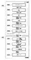
図1は、本発明の一実施形態に係る記録システムのデータ処理系のブロック構成図である。
Hereinafter, an embodiment of the present invention will be described in detail with reference to the drawings.
(Data processing system configuration)
FIG. 1 is a block diagram of a data processing system of a recording system according to an embodiment of the present invention.
本実施形態の記録装置は、大シアン(C)、小シアン(SC)、大マゼンタ(M)、小マゼンタ(SM)、イエロー(Y)、ブラック(B)のインクによって記録を行うものであり、そのために、これらの色のインクを吐出する記録ヘッドが用いられる。図1の記録システムは、このような記録ヘッドを用いる記録装置(プリンタ)1500と、ホスト装置1000もしくは画像処理装置としてのパーソナルコンピュータ(PC)を含む構成とされている。
The recording apparatus of the present embodiment performs recording with large cyan (C), small cyan (SC), large magenta (M), small magenta (SM), yellow (Y), and black (B) ink. Therefore, a recording head that discharges ink of these colors is used. The recording system in FIG. 1 includes a recording apparatus (printer) 1500 using such a recording head, and a
ホスト装置1000のオペレーティングシステムで動作するプログラムとしては、アプリケーションやプリンタドライバがある。アプリケーションJ0001は、記録装置15000で記録する画像データを作成する処理を実行する。この画像データ、もしくはその編集等がなされる前のデータは、種々の媒体を介してPCに取り込むことができる。本実施形態のPCは、例えば、ディジタルカメラで撮像したJPEG形式の画像データを、CFカードによって取り込むことができる。また例えば、スキャナで読み取ったTIFF形式の画像データや、CD−ROMに格納される画像データをも取り込むことができる。さらには、インターネットを介してウエブ上のデータを取り込むことができる。これらの取り込まれたデータはPCのモニタに表示されて、アプリケーションJ0001を介した編集、加工等がなされ、例えば、sRGB規格の画像データR、G、Bが作成される。そして記録の指示に応じて、この画像データがプリンタドライバに渡される。
Examples of programs that operate on the operating system of the
本実施形態のプリンタドライバは、その処理機能として、前段処理J0002、後段処理J0003、γ補正J0004、ハーフトーニングJ0005、および記録データ作成J0006の機能を有している。前段処理J0002は、色域(Gamut)のマッピングを行う。本実施形態の前段処理J0002は、sRGB規格の画像データR、G、Bによって再現される色域を、本記録システムの記録装置によって再現される色域内に写像する関係を内容とする3次元LUTを用い、これに補間演算を併用して、8ビットの画像データR、G、Bを記録装置の色域内のデータR、G、Bに変換するデータ変換を行う。後段処理J0003は、このように色域のマッピングがなされたデータR、G、Bに基づき、このデータが表す色を再現するインクの組み合わせに対応した色分解データY、M、SM、C、SC,Kを求める処理を行う。本実施形態では、この処理は前段処理と同様に、3次元LUTに補間演算を併用して行う。 The printer driver of this embodiment has functions of a pre-stage process J0002, a post-stage process J0003, a γ correction J0004, a halftoning J0005, and a print data creation J0006 as its processing functions. The pre-stage process J0002 performs color gamut mapping. The pre-stage process J0002 of the present embodiment includes a three-dimensional LUT having a relationship in which the color gamut reproduced by the image data R, G, B of the sRGB standard is mapped into the color gamut reproduced by the recording apparatus of the present recording system. Is used together with an interpolation operation to perform data conversion for converting 8-bit image data R, G, B into data R, G, B in the color gamut of the recording apparatus. The post-stage processing J0003 is based on the data R, G, and B in which the color gamut is mapped as described above, and the color separation data Y, M, SM, C, and SC corresponding to the combination of inks that reproduce the color represented by the data. , K is performed. In the present embodiment, this processing is performed by using an interpolation operation in combination with the three-dimensional LUT, as in the previous processing.
γ補正J0004は、後段処理J0003によって求められた色分解データの各色のデータ毎に、その階調値変換を行う。具体的には、本システムにおける記録装置の各色インクの階調特性に応じた1次元LUTを用いることにより、上記色分解データがプリンタの階調特性に線形的に対応づけられるような変換を行う。ハーフトーニングJ0005は、8ビットの色分解データY、SM、M、C、SC、Kそれぞれについて4ビットのデータに変換する量子化を行う。本実施形態では、誤差拡散法を用いて8ビットデータを4ビットデータに変換する。この4ビットデータは、記録装置におけるドット配置のパターン化処理における配置パターンを示すためのインデックスとなるデータである。最後に、記録データ作成処理J0006によって、上記4ビットのインデックスデータを内容とする記録イメージデータに記録制御情報を加えた記録データを作成する。 The γ correction J0004 performs gradation value conversion for each color data of the color separation data obtained by the post-processing J0003. Specifically, by using a one-dimensional LUT corresponding to the gradation characteristics of each color ink of the printing apparatus in this system, conversion is performed so that the color separation data is linearly associated with the gradation characteristics of the printer. . Halftoning J0005 performs quantization by converting 8-bit color separation data Y, SM, M, C, SC, and K into 4-bit data. In this embodiment, 8-bit data is converted into 4-bit data using an error diffusion method. This 4-bit data is data serving as an index for indicating an arrangement pattern in the dot arrangement patterning process in the printing apparatus. Finally, recording data is created by adding recording control information to the recording image data containing the 4-bit index data by the recording data creation process J0006.
なお、上述したアプリケーションおよびプリンタドライバの処理は、それらのプログラムに従ってCPUにより行われる。その際、プログラムはROMもしくはハードディスクから読み出されて用いられ、また、その処理実行に際してRAMがワークエリアとして用いられる。 Note that the processing of the application and printer driver described above is performed by the CPU according to these programs. At this time, the program is read from the ROM or hard disk and used, and the RAM is used as a work area when executing the processing.
記録装置は、データ処理に関して、ドット配置パターン化処理J0007およびマスクデータ変換処理J0008を行う。ドット配置パターン化処理J0007は、実際の記録画像に対応する画素毎に、記録イメージデータである4ビットのインデックスデータ(階調値情報)に対応したドット配置パターンに従って、ドット配置を行う。このように、4ビットデータで表現される各画素に対して、その画素の階調値に対応したドット配置パターンを割当てることにより、画素内の複数のエリアの各々に対してドットのオン・オフが定義され、そして1画素内の各エリア毎に「1」または「0」のインクの吐出データが配置される。 The recording apparatus performs dot arrangement patterning processing J0007 and mask data conversion processing J0008 regarding data processing. The dot arrangement patterning process J0007 performs dot arrangement according to a dot arrangement pattern corresponding to 4-bit index data (tone value information) that is recording image data for each pixel corresponding to an actual recording image. In this way, by assigning a dot arrangement pattern corresponding to the gradation value of each pixel represented by 4-bit data, dots are turned on / off for each of a plurality of areas in the pixel. And “1” or “0” ink ejection data is arranged for each area within one pixel.
このようにして得られる1ビットの吐出データは、マスクデータ変換処理J0008によってマスク処理がなされる。すなわち、記録ヘッドによる所定幅の走査領域の記録を複数回の走査で完成するための各走査の吐出データを、それぞれの走査に対応したマスクを用いた処理によって生成する。走査毎の吐出データY、M、SM、C、SC、Kは、適切なタイミングでヘッド駆動回路J0009に送られる。これにより、記録へッドJ0010が駆動され、吐出データに従ってそれぞれのインクが吐出される。なお、記録装置におけるドット配置パターン化処理J0007やマスクデータ変換処理J0018は、それら専用のハードウエア回路を用い、記録装置の制御部を構成するCPUの制御の下において実行される。 The 1-bit ejection data obtained in this way is subjected to a mask process by a mask data conversion process J0008. That is, the ejection data for each scan for completing the recording of the scanning region of the predetermined width by the recording head by a plurality of scans is generated by a process using a mask corresponding to each scan. The ejection data Y, M, SM, C, SC, and K for each scan are sent to the head drive circuit J0009 at an appropriate timing. As a result, the recording head J0010 is driven, and each ink is ejected according to the ejection data. Note that the dot arrangement patterning process J0007 and the mask data conversion process J0018 in the printing apparatus are executed under the control of the CPU constituting the control unit of the printing apparatus using these dedicated hardware circuits.
なお、これらの処理は、プログラムに従ってCPUにより行われてもよく、またPCにおける例えばプリンタドライバによって実行されるものでもよい。本発明を適用する上において、これら処理の形態が問われないことは、以下の説明からも明らかである。 These processes may be performed by the CPU according to a program, or may be executed by, for example, a printer driver in the PC. In applying the present invention, it is apparent from the following description that these processing modes are not limited.
さらに、本明細書において「画素」とは、階調表現できる最少単位のことであり、複数ビットの多値データの画像処理(上記前段、後段、γ補正、ハーフトーニング等の処理)の対象となる最少単位である。本例のドット配置パターン化処理において、1つの画素は2×4のマスで構成されるパターンに対応し、この1画素内の各マスをエリアと定義する。この「エリア」は、ドットのオン・オフが定義される最少単位である。これに関連して、前段処理J0002、後段処理J0003、γ補正J0004にいう「画像データ」は、処理対象である画素の集合を表しており、各画素が本実施形態では8ビットの階調値を内容とするデータである。また、ハーフトーニングJ0005にいう「画素データ」は、処理対象である画素データそのものを表している。本実施形態のハーフトーニングJ0005では、上記の8ビットの階調値を内容とする画素データが、4ビットの階調値を内容とする画素データ(インデックスデータ)に変換される。 Further, in this specification, the “pixel” is a minimum unit that can express gradation, and is a target of image processing of multi-bit multi-bit data (processing such as the preceding stage, the latter stage, γ correction, and halftoning). Is the smallest unit. In the dot arrangement patterning process of this example, one pixel corresponds to a pattern composed of 2 × 4 cells, and each cell in this pixel is defined as an area. This “area” is a minimum unit in which dot on / off is defined. In this connection, “image data” referred to in the pre-stage process J0002, the post-stage process J0003, and the γ correction J0004 represents a set of pixels to be processed, and each pixel has an 8-bit gradation value in this embodiment. Is the data. Further, “pixel data” referred to in halftoning J0005 represents the pixel data itself to be processed. In the halftoning J0005 of the present embodiment, the pixel data containing the 8-bit gradation value is converted into pixel data (index data) containing the 4-bit gradation value.
(インクジェット記録装置の全体構成)
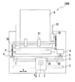
図2は、インクジェット記録装置1500の主要な機構部分の基本構成例を示す図である。
図2において、ヘッドカートリッジ1がキャリッジ2に交換可能に搭載されている。ヘッドカートリッジ1は、記録ヘッド部およびインクタンク部を有し、また記録ヘッド部を駆動するための信号などを授受するためのコネクタ(不図示)が設けられている。ヘッドカートリッジ1はキャリッジ2に位置決めして交換可能に搭載されており、キャリッジ2には、ヘッドカートリッジ1側のコネクタを介して、そのヘッドカートリッジ1に駆動信号等を伝達するためのコネクタホルダ(電気接続部)が設けられている。
(Overall configuration of inkjet recording apparatus)
FIG. 2 is a diagram illustrating a basic configuration example of main mechanism portions of the ink
In FIG. 2, a
キャリッジ2は、矢印Xの主走査方向に延在するように装置本体に設置されたガイドシャフト3に沿って、往復移動可能に案内支持されている。このキャリッジ2は、主走査モータ(キャリッジモータ)4の駆動力により、モータプーリ5、従動プーリ6、およびタイミング・ベルト7等の駆動機構を介して駆動されると共に、その位置および移動が制御される。また、キャリッジ2にはホームポジションセンサ30が設けられている。これにより、遮蔽板36の位置をキャリッジ2上のホームポジションセンサ30が通過した際に、キャリッジ2の位置を知ることが可能となる。
The
また、給紙モータ35の駆動力により、ギアを介してピックアップローラ31を回転させることにより、記録用紙やプラスチック薄板等の記録媒体8は、オートシートフィーダ(以降、「ASF」ともいう)32から一枚ずつ分離されて給紙される。更に記録媒体8は、搬送ローラ9の回転により、ヘッドカートリッジ1の吐出口面(吐出口が形成される面)と対向する位置(プリント部)を通って、矢印Yの副走査方向に搬送される。搬送ローラ9は、LFモータ(紙送りモータ)34によりギアを介して回転される。その際、記録媒体8が給紙されたか否かの判定と、給紙時における記録媒体8の先端の頭出し位置の確定は、ペーパエンドセンサ33の位置を記録媒体8が通過した時点にて行われる。更に、記録媒体8の後端の位置、および記録媒体8の実際の後端位置に基づいて現在の記録位置を割り出すためにも、ペーパエンドセンサ33は使用される。
Further, by rotating the
記録媒体8は、記録位置において平坦な記録面が形成されるように、その裏面がプラテン(不図示)により支持される。キャリッジ2に搭載されたヘッドカートリッジ1は、その吐出口面がキャリッジ2から下方へ突出するように保持されて、その吐出口面は、2組の搬送ローラ対3の間において記録媒体8と記録面と平行となる。
The back surface of the
(記録ヘッドの構成)
ヘッドカートリッジ1は、例えば、熱エネルギーを利用してインクを吐出するインクジェットヘッドカートリッジであって、熱エネルギーを発生するための電気熱変換体を備えている。すなわち、ヘッドカートリッジ1における記録ヘッド部は、その電気熱変換体が発生する熱エネルギーによってインクに膜沸騰を生じさせ、そのときの気泡の圧力を利用して、吐出口からインクを吐出することができる。もちろん、圧電素子を用いてインクを吐出する等、インクの吐出方式はいずれの方式であってもよい。
(Configuration of recording head)
The
図3は、ヘッドカートリッジ1における記録ヘッド部の主要部の模式図である。
同図において、100は、吐出口110から比較的多量(第1の吐出量)のシアンインクを吐出する大シアンドット形成用の第1記録ヘッド(C1)、101は、吐出口111から比較的少量(第1の吐出量よりも少ない第2の吐出量)のシアンインクを吐出する小シアンドット形成用の第1記録ヘッド(SC1)である。102は、吐出口112から比較的多量(第1の吐出量)のマゼンタインクを吐出する大マゼンタドット形成用の第1記録ヘッド(M1)、103は、吐出口113から比較的少量(第1の吐出量よりも少ない第2の吐出量)のマゼンタインクを吐出する小マゼンタドット形成用の第1記録ヘッド(SM1)である。104は、吐出口114からイエローインクを吐出する第1記録ヘッド(Y1)である。
FIG. 3 is a schematic diagram of the main part of the recording head portion in the
In the figure,
また105は、吐出口115からイエローインクを吐出する第2記録ヘッド(Y2)である。106は、吐出口116から比較的少量のマゼンタインクを吐出する小マゼンタドット形成用の第2記録ヘッド(SM2)、107は、吐出口117から比較的多量のマゼンタインクを吐出する大マゼンタドット形成用の第2記録ヘッド(M2)である。108は、吐出口118から比較的少量のシアンインクを吐出する小シアンドット形成用の第2記録ヘッド(SC2)、109は、吐出口119から比較的多量のシアンインクを吐出する大シアンドット形成用の第2記録ヘッド(C2)である。
記録ヘッドC1,C2の吐出口110,119は、ノズルピッチPの1/2だけ副走査方向にずれている。同様に、記録ヘッドSC1,SC2の吐出口、記録ヘッドM1,M2の吐出口、記録ヘッドSM1,SM2の吐出口、記録ヘッドY1,Y2の吐出口もそれぞれノズルピッチPの1/2だけ副走査方向にずれている。ここでは、図示しないが、ブラックインク吐出用の記録ヘッドも同様に構成されて、図3のカラーインク吐出用の記録ヘッドと共に主走査方向に並べて配備される。吐出口110,112,114,116、および118は奇数ラスターRo上に位置し、吐出口111,113,115,117、および119は偶数ラスターRe上に位置する。
The
これらの記録ヘッド群を1つとしてヘッドカートリッジ1が構成されている。ヘッドカートリッジ1において、それら個々の記録ヘッドには、上述したように吐出口列(ノズル列)が形成されている。個々の記録ヘッドにおけるノズル群は、主走査方向と交差する方向(本例では、主走査方向にほぼ直交する方向)に配列されている。厳密には、インクの吐出タイミングとの関係から、ノズル群が主走査方向に多少斜めに配列される場合もある。また、各記録ヘッドにおけるノズル群は主走査方向に並ぶように配列されている。つまり、それぞれの記録ヘッドが主走査方向に配列されて、所謂、横並び形態とされている。更に、ヘッドカートリッジ1は、上記複数の記録ヘッドが一体に形成された構成であってもよいし、上記複数の記録ヘッドが別体で形成された構成であってもよい。
The
(制御系の構成)
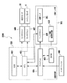
図4は、このような記録装置の制御系のブロック構成図である。
図4において、400は記録信号を入力するインターフェース、401はMPU、402はMPU401が実行する制御プログラムを格納するプログラムROMである。403は、各種データ(記録信号や記録ヘッドに供給される画像データ等)を保存しておくダイナミック型のRAM(DRAM)であり、記録ドット数や記録ヘッドの交換回数等も記憶することができる。404は、記録ヘッド部501の記録ヘッド201に対する画像データの供給制御を行うゲートアレイであり、インターフェース400、MPU401、DRAM403の相互間におけるデータの転送制御も行う。前述したように、4は、記録ヘッド201をキャリッジ2と共に主走査方向に搬送するためのキャリッジモータであり、34は、記録媒体8を副走査方向に搬送するための搬送モータである。407、408は、キャリッジモータ4、搬送モータ34を駆動するためのモータドライバである。409は、記録ヘッド201を駆動するためのヘッドドライバである。
(Control system configuration)
FIG. 4 is a block diagram of the control system of such a recording apparatus.
In FIG. 4, 400 is an interface for inputting a recording signal, 401 is an MPU, and 402 is a program ROM for storing a control program executed by the
図5は、記録制御部500のブロック構成図である。
記録制御部500において、1001は、ホスト装置1000からの量子化データを受信する受信バッファ、1002は、ドット配置パターンの同期の必要性を判定する同期処理判定モジュールである。1003は、同期処理ドット配置パターンを格納するドット配置パターン格納ユニットである。1004はドットドット配置割り付けモジュールであり、ドット配置パターンを用いて、受信バッファ1001内の量子化データにドット配置パターンを割り付ける。展開バッファ(プリントバッファ)1005は、ドット配置パターン割り付けモジュール1004により割り付けられたドット配置パターンを用いて、量子化データを展開する。同期処理判定モジュール1002とドット配置パターン割り付けモジュール1004は、ROM402に予め格納されていて、MPU401にて実行されるソフトウエアモジュールである。また、受信バッファ1001、ドット配置パターン格納ユニット1002、および展開バッファ1004は、DRAM403の所定のアドレス領域に用意される。
FIG. 5 is a block configuration diagram of the
In the
ドット配置パターン格納ユニット1003には、後述するように複数のドット配置パターンが格納されており、それらの中から何れかのパターンが選択され、その選択されたパターンが展開バッファ1005に展開される。本実施形態において、記録装置1500は、ホスト装置1000にて600(横)×600(縦)dpiの解像度で9値(4ビット)に量子化された画像データを2400(横)×1200(縦)dpi(4×2のドット配置パターン)の画像データに展開して、記録をする。
The dot arrangement
(ドット配置パターン)
図6は、ドット配置パターン格納ユニット1004に格納されているドット配置パターンの説明図である。ドット配置パターンは、色インク毎に、レベル0からレベル8までの信号レベル(階調レベル)の量子化データに対応するように、番号(NO.1,NO.2)に割り付けて格納されている。図6は、小シアン(SC)ドット形成用と小マゼンタ(SM)ドット形成用のドット配置パターンを代表して示している。ここでは便宜上、同一レベルの量子化データに対して、最大2種類(NO.1,NO.2)のパターンまで格納できるものとしている。しかし、これに限られるものではなく、記録装置の構成等に応じて格納するパターン数を最適に設定することができる。また、同一レベルの量子化データに対応するドット配置パターンが2パターン以上ない場合には、便宜上同じパターンを用いる。
(Dot arrangement pattern)
FIG. 6 is an explanatory diagram of the dot arrangement pattern stored in the dot arrangement
本例のドット配置パターンは、600dpi×600dpiの1画素を2×4の8つのエリアに分けている。奇数ラスターRo上のエリアには、図3のように、その奇数ラスターRo上に吐出口が位置する記録ヘッドによってドットが形成される。同様に、偶数ラスターRe上のエリアには、その偶数ラスターRe上に吐出口か位置する記録ヘッドによってドットが形成される。例えば、図6のように小シアンドットを形成する場合には、奇数ラスターRo上のエリアには第2記録ヘッドSC2によってドットが形成され、偶数ラスターRe上のエリアには第1記録ヘッドSC1によってドットが形成される。同様に、小マゼンタドットを形成する場合には、奇数ラスターRo上のエリアには第2記録ヘッドSM2によってドットが形成され、偶数ラスターRe上のエリアには第1記録ヘッドSM1によってドットが形成される。 In the dot arrangement pattern of this example, one pixel of 600 dpi × 600 dpi is divided into 8 areas of 2 × 4. In the area on the odd raster Ro, dots are formed by the recording head in which the ejection openings are located on the odd raster Ro as shown in FIG. Similarly, dots are formed in the area on the even-numbered raster Re by the recording head located at the ejection port on the even-numbered raster Re. For example, when forming small cyan dots as shown in FIG. 6, dots are formed by the second recording head SC2 in the area on the odd raster Ro and by the first recording head SC1 in the area on the even raster Re. Dots are formed. Similarly, when forming small magenta dots, dots are formed by the second recording head SM2 in the area on the odd raster Ro, and dots are formed by the first recording head SM1 in the area on the even raster Re. The
このようなドット配置パターンは、前述したホスト装置におけるハーフトーニングJ0005後の量子化データが示す階調レベル(出力レベル)に対応する。 Such a dot arrangement pattern corresponds to the gradation level (output level) indicated by the quantized data after halftoning J0005 in the host device described above.
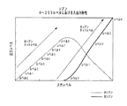
図7は、ホスト装置おけるハーフトーニングJ0005の前後における信号レベルを表したものである。この図7は、大小シアンインク用のデータC、SCを例として、その入力レベル0〜255(γ補正J0004により得られた信号レベル0〜255)に対するハーフトーニングJ0005後の出力レベルを表している。
FIG. 7 shows signal levels before and after halftoning J0005 in the host device. FIG. 7 shows the output levels after halftoning J0005 with respect to the
本例においては、出力レベルが小シアンドット形成用のレベル0から8、および大シアンドット形成用のレベル0から4に対応付けられる。このように、小シアンドット形成用のレベルを9値化、大シアンドット形成用のレベルを5値化し、それぞれのレベルに、図6中のドット配置パターンのNO.1またはNO.2を選択して割り付ける。
In this example, output levels are associated with
図7において、例えば、入力レベル128の中間調領域においては、第1,第2記録ヘッドSC1,SC2を用いて、小シアンドットによって画像が記録されることが分かる。また、カラー画像の中間調領域を記録する場合には、記録ヘッドSC1,SC2の他、記録ヘッドSM1,SM2およびY1,Y2が用いられることになる。 In FIG. 7, for example, in the halftone area of the input level 128, it can be seen that an image is recorded by small cyan dots using the first and second recording heads SC1 and SC2. When recording a halftone area of a color image, the recording heads SM1, SM2 and Y1, Y2 are used in addition to the recording heads SC1, SC2.
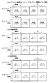
小シアンドットによって画像を記録する場合、例えば、同一レベル4の階調が連続する画像は、図6における小シアンドット用のレベル4のドット配置パターンが図8(a)のように連続的に用いられることになる。同様に、小マゼンタドットによって画像を記録する場合、例えば、同一レベル4の階調が連続する画像は、図6における小マゼンタドット用のレベル4のドット配置パターンが図8(a)のように連続的に用いられることになる。
When recording an image using small cyan dots, for example, in an image having the
小シアンドット用のレベル4のドット配置パターンにおいて、No.1のパターンが選択された場合には、第2記録ヘッドSC2によって奇数ラスターRo上にドットが形成され、またNo.2のパターンが選択された場合には、第1記録ヘッドSC1によって偶数ラスターRe上にドットが形成される。同様に、小マゼンタドット用のレベル4のドット配置パターンにおいて、No.1のパターンが選択された場合には、第2記録ヘッドSM2によって奇数ラスターRo上にドットが形成され、またNo.2のパターンが選択された場合には、第1記録ヘッドSM1によって偶数ラスターRe上にドットが形成される。
In the
同じ画素内に、このようなレベル4の小シアンドットと小マゼンタドットを連続して形成するときに、仮に、画素列内における画像データの有無を判別して、それぞれのパターンのNO.1とNO.2を交互に切り替えるように選択した場合には、図8(b)または(c)のようにドットが形成されることになる。図8(b)の場合、同じ画素内の小シアンドットと小マゼンタドットは、第2記録ヘッドSC2と第1記録ヘッドSM1、または第1記録ヘッドSC1と第2記録ヘッドSM2によって、異なるラスター上に形成される。一方、図8(c)の場合、同じ画素内の小シアンドットと小マゼンタドットは、第2記録ヘッドSC2と第2記録ヘッドSM2、または第1記録ヘッドSC1と第1記録ヘッドSM1によって、同一ラスター上に形成される。画素列内における画素データの有無を小シアン・小マゼンタそれぞれ独立に判別し、画素データが存在する度にそれぞれのパターンのNO.1とNO.2を交互に選択した場合、ドット配置が図8(b)または(c)のいずれになるかは、ほぼ同じ確率となる。
When
図8(b),(c)のドット配置には、インクの着弾ずれとの関係において、次のような特性がある。 The dot arrangements shown in FIGS. 8B and 8C have the following characteristics in relation to the landing deviation of ink.
図8(b)のドット配置において、インクの着弾位置が副走査方向へ約5μmずれた場合には図9(a)のようにドットが形成され、インクの着弾位置が副走査方向に約10μmずれた場合には図9(b)のようにドットが形成される。主に中間調領域として使用されるレベル4においては、図9(a),(b)のように、同一画素内における異なるラスター上に異色のドットが配置された場合に、副走査方向への着弾位置のずれによって次のような不具合を生じるおそれがある。
(1)エリアファクターが比較的大きく変化し、相対的に濃度の高い領域と低い領域が発生する。
(2)異色のドット同士の干渉の程度が相対的に高い領域と小さい領域が発生する。
In the dot arrangement of FIG. 8B, when the ink landing position is shifted by about 5 μm in the sub-scanning direction, dots are formed as shown in FIG. 9A, and the ink landing position is about 10 μm in the sub-scanning direction. In the case of deviation, dots are formed as shown in FIG. In
(1) The area factor changes relatively greatly, and a relatively high density area and a low density area are generated.
(2) An area where the degree of interference between different color dots is relatively high and a small area are generated.
これらの要因により、記録した画像中に、副走査方向の着弾ずれが生じる周期で濃度ムラ、色ムラが発生するおそれがある。 Due to these factors, density unevenness and color unevenness may occur in a recorded image at a period in which landing deviation in the sub-scanning direction occurs.
一方、図8(c)のドット配置において、インクの着弾位置が副走査方向へ約5μmずれた場合には図10(a)のようにドットが形成され、インクの着弾位置が副走査方向に約10μmずれた場合には図10(b)のようにドットが形成される。図10(a),(b)のように、同一画素内における同一ラスター上に異色のドットが配置された場合には、着弾位置が副走査方向へずれてもエリアファクターの変化が小さい。そのため、図8(b)のドット配置の場合よりも濃度ムラの発生を抑えることができる。 On the other hand, in the dot arrangement of FIG. 8C, when the ink landing position is shifted by about 5 μm in the sub-scanning direction, dots are formed as shown in FIG. 10A, and the ink landing position is in the sub-scanning direction. When the displacement is about 10 μm, dots are formed as shown in FIG. As shown in FIGS. 10A and 10B, when different color dots are arranged on the same raster in the same pixel, the change in area factor is small even if the landing position is shifted in the sub-scanning direction. Therefore, the occurrence of density unevenness can be suppressed as compared with the case of the dot arrangement of FIG.
(インクの着弾位置のずれとノズル間の距離との関係)
図11および図12は、副走査方向におけるインクの着弾位置のずれと、記録ヘッドにおけるノズル列間の距離との関係の説明図である。
(Relationship between deviation of ink landing position and distance between nozzles)
11 and 12 are explanatory diagrams of the relationship between the deviation of the ink landing position in the sub-scanning direction and the distance between the nozzle rows in the recording head.
本例の場合、記録ヘッドC1,SC1,M1,SM1,Y1,Y2,SM2,M2,SC2,およびC2のそれぞれのノズル列は、図11のような距離を隔てて並んでいる。記録ヘッドC1のノズル列の位置を基準とした場合、そのノズル列から最も遠い記録ヘッドC2のノズル列までの間の距離は約6.04mmとなる。 In the case of this example, the nozzle arrays of the recording heads C1, SC1, M1, SM1, Y1, Y2, SM2, M2, SC2, and C2 are arranged at a distance as shown in FIG. When the position of the nozzle row of the recording head C1 is used as a reference, the distance from the nozzle row to the nozzle row of the recording head C2 farthest from that nozzle row is about 6.04 mm.
レベル4の小シアンドットと小マゼンタドットを同じ画素内に連続して形成する場合、記録ヘッドSC1,SM1のノズル列(以下、それぞれを「ノズル列SC1」,「SM1」ともいう)を用いたときには図12(a)のようにインクの着弾位置がずれ、また記録ヘッドSC1,SM2のノズル列(以下、それぞれを「ノズル列SC1」,「SM2」ともいう)を用いたときには図12(b)のようにインクの着弾位置がずれた。さらに、記録ヘッドSC1,SC2のノズル列(以下、それぞれを「ノズル列SC1」,「SC2」ともいう)を用いてレベル4の小シアンドットを連続して形成したときには、図12(c)のようにインクの着弾位置がずれた。
When forming
図12(a),(b),(c)において、主走査方向の位置A(約70mm付近)、および位置B(約155mm付近)における副走査方向の着弾ずれ量の差を比較する。位置Aにおいては、何れのノズル列の関係においても着弾ずれ量の差が約3μm程度と比較的少ない。一方、位置Bにおいては、図12(a)のようにノズル列間の距離が短いノズル列SC1,SM1の関係においては副走査方向へのずれ量の差が少ない。しかし、図12(b)および(c)のように、主走査方向のノズル列間の距離が長いノズル列SC1,SM1およびSC1,SC2の関係においては、副走査方向へのずれ量の差が約8μm程度と大きくなった。つまり、ノズル列間の距離が離れる程、ずれ量が大きくなる傾向にある。この理由は、未だ解明されていないが、本発明者は次のように推測している。記録ヘッドを保持するキャリッジの摺動面(キャリッジが主走査したときの面)は必ずしも平滑でない。記録ヘッドを保持するキャリッジの摺動面が平滑性に不均一な部分が存在すると、主走査時に記録ヘッドの絶対位置が副走査方向にずれる場合がある。この平滑性の周期に準じた副走査方向への着弾位置ずれは、更に記録に用いるノズル列が複数になると、その着弾位置ずれが列間距離に応じた形で位相ずれを発生し、列間における副走査方向へのずれが列間距離に比例する形で大きくなる。 12A, 12 </ b> B, and 12 </ b> C, the difference in the amount of landing deviation in the sub-scanning direction at the position A (approximately 70 mm) in the main scanning direction and the position B (approximately 155 mm) is compared. At position A, the difference in the amount of landing deviation is relatively small, about 3 μm, in any nozzle row relationship. On the other hand, at the position B, as shown in FIG. 12A, in the relationship between the nozzle rows SC1 and SM1 where the distance between the nozzle rows is short, the difference in the shift amount in the sub-scanning direction is small. However, as shown in FIGS. 12B and 12C, in the relationship between the nozzle rows SC1, SM1 and SC1, SC2 where the distance between the nozzle rows in the main scanning direction is long, there is a difference in the amount of deviation in the sub-scanning direction. The size increased to about 8 μm. That is, as the distance between the nozzle rows increases, the amount of deviation tends to increase. The reason for this has not been clarified yet, but the present inventor speculates as follows. The sliding surface of the carriage that holds the recording head (the surface when the carriage performs main scanning) is not necessarily smooth. If the sliding surface of the carriage holding the recording head has a non-uniform portion in smoothness, the absolute position of the recording head may shift in the sub-scanning direction during main scanning. The landing position deviation in the sub-scanning direction in accordance with the smoothness cycle is such that when a plurality of nozzle rows are used for recording, the landing position deviation causes a phase deviation in a form corresponding to the distance between the rows, The deviation in the sub-scanning direction increases in a form proportional to the inter-column distance.
図8(b)のようなドット配置においては、同一画素の記録に用いられるノズル列はSC1とSM2、もしくはSM1とSC2となり、これらはノズル列間の距離が大きい組合せとなる。そのため、副走査方向におけるインクの着弾ずれ量の差が大きくなり、図9(a),(b)のような状態が生じやすくなる。この結果、シアンとマゼンタインクのドットが形成されるブルーの中間調画像において、主走査方向に周期的な濃度ムラが発生しやすくなる。 In the dot arrangement as shown in FIG. 8B, the nozzle rows used for recording the same pixel are SC1 and SM2, or SM1 and SC2, and these are combinations with a large distance between the nozzle rows. For this reason, the difference in the amount of ink landing deviation in the sub-scanning direction becomes large, and the states shown in FIGS. 9A and 9B are likely to occur. As a result, in the halftone image of blue in which dots of cyan and magenta ink are formed, periodic density unevenness is likely to occur in the main scanning direction.
一方、図8(c)のようなドット配置においては、同一画素の記録に用いられるノズル列SC1とSM1、もしくはSM2とSC2となり、これらはノズル列間の距離が小さい組合せとなる。そのため、副走査方向におけるインクの着弾ずれ量の差が小さくなる。仮に、復走査方向におけるインクの着弾ずれが生じたとしても図10(a),(b)のような状態となり、主走査方向における周期的な濃度ムラは発生し難い。 On the other hand, in the dot arrangement as shown in FIG. 8C, the nozzle rows SC1 and SM1 or SM2 and SC2 are used for recording the same pixel, and these are combinations with a small distance between the nozzle rows. For this reason, the difference in the amount of ink landing deviation in the sub-scanning direction is reduced. Even if the landing deviation of the ink in the backward scanning direction occurs, the state becomes as shown in FIGS. 10A and 10B, and periodic density unevenness hardly occurs in the main scanning direction.
本実施形態においては、このようなインクの着弾位置のずれとノズル間の距離との関係を考慮して、後述するようなドット配置パターンの同期処理を実行する。 In the present embodiment, in consideration of the relationship between the displacement of the ink landing position and the distance between the nozzles, a dot arrangement pattern synchronization process as described later is executed.
(データの展開処理)
図13は、本実施形態におけるデータ展開処理を説明するためのフローチャートである。これらの処理は、主に、図5中の同期処理判定モジュール1002、およびドット配置パターン割り付けモジュール1004により行われる。
(Data expansion process)
FIG. 13 is a flowchart for explaining data expansion processing in the present embodiment. These processes are mainly performed by the synchronization
図13において、まず、ホスト装置1000から転送された4ビットの量子化データ(0〜8の9値のデータ)を受信し、その受信したデータを受信バッファ1001に格納する(ステップS1)。次のステップS2では、受信バッファ1001内に格納したデータの中から、1画素分の4ビットの量子化データを読み出す。次のステップS3においては、読み出した量子化データの中に、後述するドット配置パターンの同期処理が必要なインク色のデータが含まれているか否かを判定する。本実施形態において、同期処理が必要なインク色はシアンおよびマゼンタである。このような同期処理が必要なシアンおよびマゼンタインクのデータが含まれている場合には、ステップS4において、そのデータが同期処理を必要とするレベルであるか否かを判定する(ステップS4)。本実施形態では、主に中間調領域を記録するための階調レベル3〜7に対応する小シアン・小マゼンタのデータを同期処理の対象とする。なお、本例では、同期処理の対象を小シアン・小マゼンタの階調レベル3〜7に限っているが、小シアン・小マゼンタの全階調を同期処理の対象としてもよい。 同期処理対象のデータに関しては、後述する同期処理(ステップS5)によって、そのデータに用いるドット配置パターン番号(NO.1またはNO.2)を決定し、次のステップS6において、その番号に対応するパターンを選択する。そして、その選択したパターンを展開バッファ1005に展開する(ステップS7)。
In FIG. 13, first, 4-bit quantized data (9-value data of 0 to 8) transferred from the
一方、同期処理対象ではないデータに関しては、ステップSにおいて、そのデータのレベルに対応するドット配置パターンとして、NO.1またはNO.2のいずれかを選択する。本例においては、同期処理対象ではないデータに関しては、画素列内における画素データの有無を識別して、同一レベルの2パターン(NO.1,NO.2)を交互に選択する。そして、その選択したパターンを展開バッファ1005に展開する(ステップS7)。なお、同期処理対象ではないデータに関しては、同一レベルの2パターン(NO.1,NO.2)を交互に選択することに限られるものではなく、例えば、この2パターン(NO.1,NO.2)をランダムに選択する形態であってもよいし、また、同一レベルのパターンが3種類以上存在する場合には、これら3パターンの所定の順序(例えば、NO.1→NO.2→NO.3→NO.1・・・)で繰り返し選択する形態であってもよい。 On the other hand, for data that is not subject to synchronization processing, in step S, as a dot arrangement pattern corresponding to the level of the data, NO. 1 or NO. 2 is selected. In this example, for data that is not subject to synchronization processing, the presence or absence of pixel data in the pixel column is identified, and two patterns (NO.1, NO.2) at the same level are selected alternately. Then, the selected pattern is developed in the development buffer 1005 (step S7). For data that is not subject to synchronization processing, it is not limited to alternately selecting two patterns (NO.1, NO.2) at the same level, for example, these two patterns (NO.1, NO.2). 2) may be selected at random, and when there are three or more patterns of the same level, a predetermined order of these three patterns (for example, NO.1 → NO.2 → NO .3 → NO.1 ...) may be selected repeatedly.
その後、ステップS8において、ステップS1にて受信バッファ1001に格納した画像データの全画素について、展開バッファ1004への展開を完了したか否か確認する。そして、まだ全画素についての展開が終了していなときにはステップS2に戻り、それが終了したときには本展開処理を終了する。
Thereafter, in step S8, it is confirmed whether or not the development to the
(同期処理)
図14は、同期処理の一例を説明するための図である。
本実施形態においては、主走査方向における周期的な濃度ムラが発生しやすい中間調領域に着目し、その領域の記録に用いられる階調レベルのデータにのみ同期処理を適用する。更に本形態では、小ドットを形成する小シアンドット形成用のデータ、および小マゼンタドット形成用のデータに同期処理を適用する。大ドット形成用のデータに関しては、想定される副走査方向の着弾ずれが生じた場合に、
(1)エリアファクターの変化が小さく、
(2)異色のドット同士の干渉が生じるものの、濃度が高いために目立ちにくい
ために、同期処理は適用しない。
(Synchronous processing)
FIG. 14 is a diagram for explaining an example of the synchronization processing.
In the present embodiment, attention is paid to a halftone area in which periodic density unevenness is likely to occur in the main scanning direction, and the synchronization process is applied only to gradation level data used for recording in the area. Further, in this embodiment, the synchronization process is applied to data for forming small cyan dots for forming small dots and data for forming small magenta dots. Regarding the data for large dot formation, when landing deviation in the assumed sub-scanning direction occurs,
(1) Area factor change is small,
(2) Although interference between dots of different colors occurs, since the density is high, it is difficult to stand out, so the synchronization processing is not applied.
本例においては、同期処理を要する中間調領域のデータの一例として、図14(a)のように、小シアンドット形成用と小マゼンタドット形成用のデータレベルがいずれも4の場合、つまり前述した図8(a)と同様の場合を想定する。また、同期処理を要する中間調領域のデータとして、例えば、前者のデータレベルが4、後者のデータレベルが3の場合なども含まれることは勿論である。 In this example, as an example of halftone area data that requires synchronization processing, as shown in FIG. 14A, when the data levels for forming small cyan dots and for forming small magenta dots are both 4, that is, as described above. A case similar to that shown in FIG. Further, as a halftone area data requiring synchronization processing, for example, the case where the former data level is 4 and the latter data level is 3, for example, is included.
仮に、これらのデータに同期処理しなかった場合には、他のデータと同様に、単に、小シアン・小マゼンタ独立で画素列内における画素データの有無を識別し、小シアン・小マゼンタ独立で同一レベルの2パターン(NO.1,NO.2)が交互に選択されることになる。この場合には、図14(b)のように、同一画素に割り当てられる小シアンドット用のパターンと小マゼンタドット用のパターンの組み合わせとして、パターンNO.1とNO.2の組み合わせが生じる可能性が多分にある。この図14(b)のパターンの組み合わせは、前述した図8(b)のドット配置に相当する。そのため、前述したように、ノズル間の距離が比較的大きいノズル列SC1とSM2の組み合わせ、およびノズル間の距離が比較的大きいノズル列SC2とSM1の組み合わせによって、同一画素内にドットが形成されることになり、主走査方向における周期的な濃度ムラが発生しやすくなる。 If these data are not synchronized with each other, as with other data, the presence / absence of pixel data in the pixel array is simply identified independently of small cyan / small magenta, and small cyan / small magenta independent. Two patterns (NO.1, NO.2) at the same level are selected alternately. In this case, as shown in FIG. 14B, a pattern NO. As a combination of a pattern for small cyan dots and a pattern for small magenta dots assigned to the same pixel is used. 1 and NO. There is likely a combination of the two. The combination of patterns shown in FIG. 14B corresponds to the dot arrangement shown in FIG. Therefore, as described above, dots are formed in the same pixel by the combination of the nozzle rows SC1 and SM2 having a relatively large distance between the nozzles and the combination of the nozzle rows SC2 and SM1 having a relatively large distance between the nozzles. Therefore, periodic density unevenness in the main scanning direction is likely to occur.
そこで本実施形態においては、前述したように、受信バッファ1001から1画素分の量子化データを読み出した後に、それが図14(a)のようなデータであるときは、そのデータに対して同期処理が必要であると判定する。そして、そのデータに対する同期処理により、図14(c)のように、同一画素に割り当てる小シアンドット用のパターンと小マゼンタドット用のパターンの組み合わせを決定し、それらのパターンをNO.1同士の組み合わせ、またはNO.2同士の組み合わせとする。このパターンの組み合わせを決定する手法としては、小シアンデータと小マゼンタデータが含まれている画素が発生する度に、パターンNO.1の組合せとパターンNO.2の組合せを交互に選択する手法を用いる。
Therefore, in the present embodiment, as described above, when the quantized data for one pixel is read from the
この図14(c)のパターンの組み合わせは、前述した図8(c)のドット配置に相当する。そのため、前述したように、ノズル間の距離が比較的小さいノズル列SC1とSM1の組み合わせ、およびノズル間の距離が比較的小さいノズル列SC2とSM2の組み合わせによって、同一画素内にドットが形成されることになる。この結果、中間調レベルにおいて発生しやすい主走査方向の周期的な濃度ムラを軽減することができる。また、同期処理が不要なレベルのデータに対しては、同期処理を省略することができる。 The combination of patterns shown in FIG. 14C corresponds to the dot arrangement shown in FIG. Therefore, as described above, dots are formed in the same pixel by the combination of the nozzle rows SC1 and SM1 having a relatively small distance between the nozzles and the combination of the nozzle rows SC2 and SM2 having a relatively small distance between the nozzles. It will be. As a result, periodic density unevenness in the main scanning direction, which is likely to occur at the halftone level, can be reduced. Also, the synchronization process can be omitted for data at a level that does not require the synchronization process.
以上のように本実施形態においては、複数のインク色毎の記録素子に対応するように、画像データを所定の解像度でn値化(n≧3)し、それぞれの量子化されたデータをインク色毎に独立して、L(横)×M(縦)のドット配置パターンに割り付ける。その際に、特定のレベルの量子化データ、すなわち量子化された所定レベルのデータに対しては、パターンが異なる複数のドット配置パターンの中から特定のパターンを選択する。そして、異なるインク色のデータに対して、特定のパターンの組み合わせを割り付ける。 As described above, in this embodiment, image data is n-valued (n ≧ 3) at a predetermined resolution so as to correspond to a plurality of recording elements for each ink color, and each quantized data is converted into ink. Independently for each color, it is assigned to a dot arrangement pattern of L (horizontal) × M (vertical). At that time, for a specific level of quantized data, that is, quantized data of a predetermined level, a specific pattern is selected from a plurality of dot arrangement patterns having different patterns. A specific pattern combination is assigned to data of different ink colors.
その特定のパターンは、異なるインク色のドットを形成するためのノズル列として、それらのノズル間の距離が小さいものが同一画素の記録に用いられるように、異なる色のインクデータを含む同一画素の記録に用いるノズル列を特定するものである。また、その特定のパターンは、異なるインク色のデータレベルが4のときには、前述したように、(L×M)のドット配置パターンにおける同一のラスター上に同数のドットを割り付けて、奇数ラスターと偶数ラスターとの間におけるドットの配分を不均等とする。 The specific pattern is that nozzle arrays for forming dots of different ink colors are used for recording the same pixel including ink data of different colors so that nozzles having a small distance between the nozzles are used for recording the same pixel. The nozzle array used for recording is specified. In the specific pattern, when the data level of different ink color is 4, as described above, the same number of dots are allocated on the same raster in the (L × M) dot arrangement pattern, and the odd and even rasters are assigned. Dot distribution of dots between rasters is uneven.
このように特定のパターンを割り付けることにより、比較的解像度の高い記録を行うインクジェット記録装置において、記録ヘッドの取り付け精度や機構部の精度に起因する記録画像の劣化、特に、中間調領域において異なるインク色間で発生する周期的な濃度ムラの発生を抑制することができる。 By assigning a specific pattern in this manner, in an ink jet recording apparatus that performs recording with a relatively high resolution, the deterioration of the recorded image due to the accuracy of mounting of the recording head and the accuracy of the mechanism portion, particularly the different ink in the halftone area Generation of periodic density unevenness occurring between colors can be suppressed.
また、本実施形態の記録ヘッドは、各インク色毎に対して対のノズル列を備えた構成となっており、対のノズル列に対してデータをほぼ均等に分配することによって、それぞれのノズル列の記録素子に対する負荷を分散させている。このような記録ヘッドを用いる場合に、前述したような同期処理を行うことによって、記録素子に対する負荷の分散ができなくなるおそれがある。しかし、この同期処理が中間調レベルに対してのみに制限されること、また一般的に、中間調の画像が均一レベルで記録されることを考慮すれば、特定のノズル列にデータが集中して分配されることはなく、実用上問題はない。 In addition, the recording head of the present embodiment has a configuration including a pair of nozzle rows for each ink color, and by distributing data almost evenly to the pair of nozzle rows, each nozzle The load on the recording elements in the row is distributed. When such a recording head is used, there is a possibility that the load cannot be distributed to the recording elements by performing the synchronization process as described above. However, considering that this synchronization processing is limited only to the halftone level, and that halftone images are generally recorded at a uniform level, data is concentrated on a specific nozzle row. There is no problem in practical use.
(第2の実施形態)
上記第1の実施形態では、同期処理の対象画素(小シアンデータと小マゼンタデータを含む画素)が発生する度にパターンNO.1の組合せとパターンNO.2の組合せを交互に選択することにより、ドット配置パターンの同期処理を実現しているが、本実施形態では、このドット配置パターンの同期処理の手法を上記第1の実施形態とは異ならせた点に特徴がある。ドット配置パターンの同期処理の手法が異なる以外は上記第1の実施形態と同じであるので、ここではドット配置パターンの同期処理の手法についてのみ説明する。
(Second Embodiment)
In the first embodiment, each time a target pixel for synchronization processing (a pixel including small cyan data and small magenta data) is generated, the combination of the pattern No. 1 and the combination of the pattern NO. 2 are alternately selected. The dot arrangement pattern synchronization processing is realized, but this embodiment is characterized in that the dot arrangement pattern synchronization processing method is different from that of the first embodiment. Since the method is the same as that of the first embodiment except that the dot arrangement pattern synchronization processing method is different, only the dot arrangement pattern synchronization processing method will be described here.
本実施形態では、主走査方向の画素位置と選択対象パターンとを予め対応付けておき、画素データの位置に応じてパターンを選択することにより、ドット配置パターンの同期処理を実現する。具体的には、図14(C)に示される600dpi×600dpi相当の複数の画素のうち、奇数番目に相当する画素(左から1番目、3番目、・・・、N(Nは奇数)番目)には小シアン・小マゼンタ共にパターンNO.1を対応付けておき、偶数番目に相当する画素(左から2番目、4番目、・・・、N+1(Nは奇数)番目)には小シアン・小マゼンタ共にパターンNO.2を対応付けておく。そして、奇数番目に相当する画素を記録する場合には小シアン・小マゼンタのいずれもパターンNO.1を用いるようにし、偶数番目に相当する画素を記録する場合には小シアン・小マゼンタのいずれもパターンNO.2を用いるようにする。 In this embodiment, the pixel arrangement in the main scanning direction is associated with the selection target pattern in advance, and the dot arrangement pattern synchronization process is realized by selecting the pattern according to the position of the pixel data. Specifically, out of a plurality of pixels corresponding to 600 dpi × 600 dpi shown in FIG. 14C, pixels corresponding to odd numbers (first, third from the left,..., N (N is an odd number) ) Includes pattern NO. For both small cyan and small magenta. 1 is associated with the pixel corresponding to the even-numbered pixel (second from the left, fourth,..., N + 1 (N is an odd number)) for both small cyan and small magenta. 2 is associated. When recording odd-numbered pixels, pattern NO. Is used for both small cyan and small magenta. 1 is used, and when even-numbered pixels are recorded, pattern NO. 2 is used.
この構成によれば、小シアンデータと小マゼンタデータを含む奇数画素を記録する場合には必ずパターンNO.1の組合せが用いられるため、主走査方向のノズル列間の距離が比較的小さいノズル列SC2とSM2の組み合わせで奇数画素を記録することが可能となる。同様に、小シアンデータと小マゼンタデータを含む偶数画素を記録する場合には必ずパターンNO.2の組合せが用いられるため、主走査方向のノズル列間の距離が比較的小さいノズル列SC1とSM1の組み合わせで偶数画素を記録することが可能となる。このように本例によれば、奇数画素と偶数画素からなる全画素において、小シアンと小マゼンタのドット配置パターンの同期処理がなされることになる。 According to this configuration, when recording odd pixels including small cyan data and small magenta data, the pattern NO. Since a combination of 1 is used, it is possible to record odd pixels with a combination of the nozzle rows SC2 and SM2 in which the distance between the nozzle rows in the main scanning direction is relatively small. Similarly, when recording even-numbered pixels including small cyan data and small magenta data, the pattern NO. Since the combination of 2 is used, even-numbered pixels can be recorded by the combination of the nozzle rows SC1 and SM1 having a relatively small distance between the nozzle rows in the main scanning direction. As described above, according to this example, the dot arrangement pattern of the small cyan and the small magenta is synchronized in all the pixels including the odd pixels and the even pixels.
なお、この構成の場合、小シアンと小マゼンタが共存しない画素、つまり、同期処理が必要でない画素であっても、同期処理が必要な画素(小シアンと小マゼンタが共存する画素)と同様、画素位置に応じたパターンが選択される。従って、同期処理が必要な画素か否かを判定する必要はない。 In the case of this configuration, pixels that do not coexist with small cyan and small magenta, that is, pixels that do not require synchronization processing, as well as pixels that require synchronization processing (pixels where small cyan and small magenta coexist), A pattern corresponding to the pixel position is selected. Therefore, it is not necessary to determine whether or not the pixel requires synchronization processing.
また、本例において、画素位置に応じたパターン選択を行うインク種は、少なくとも、同期処理の対象となる小シアンおよび小マゼンタであればよく、その他のインク種(シアン、マゼンタ、イエロー、ブラック)についてのパターン選択は任意である。すなわち、画素データが発生する度にランダムあるいは交互にパターンNO.1とパターンNO.2を選択してもよいし、あるいは、同期処理の対象となる小シアンおよび小マゼンタと同様、画素位置に応じて選択パターンを固定させておいてもよい。 Further, in this example, the ink types for performing pattern selection according to the pixel position may be at least small cyan and small magenta to be subjected to synchronization processing, and other ink types (cyan, magenta, yellow, black). The pattern selection for is arbitrary. That is, every time pixel data is generated, pattern No. 1 and pattern No. 2 may be selected randomly or alternately, or, depending on the pixel position, as in the case of small cyan and small magenta to be subjected to synchronization processing. Alternatively, the selection pattern may be fixed.
このように本実施形態によれば、主走査方向のノズル列間の距離が比較的小さいノズル列の組み合わせ(SC1とSM1、SM2とSM2、)で同一画素の記録を行えるように、ドット配置パターンの同期処理を行っているため、主走査方向に周期的に生じる濃度ムラの発生を軽減することができる。 As described above, according to the present embodiment, the dot arrangement pattern is such that the same pixel can be recorded by a combination of nozzle rows (SC1 and SM1, SM2 and SM2, and the like) having a relatively small distance between the nozzle rows in the main scanning direction. Therefore, density unevenness that occurs periodically in the main scanning direction can be reduced.
(第3の実施形態)
上記第1〜第2の実施形態では、同期処理の例として、同一画素を記録するのにパターンNO.1同士の組合せを用いること、あるいはパターンNO.2同士の組合せを用いることを例に挙げたが、本発明はこれに限られるものではない。
(Third embodiment)
In the first to second embodiments, as an example of the synchronization process, the combination of patterns No. 1 or the combination of patterns No. 2 is used to record the same pixel. However, the present invention is not limited to this.
図12を用いて説明したように、本発明では、主走査方向のノズル列間の距離が比較的小さいノズル列の組み合わせで同一画素が記録できるようにドット配置パターンを選択する点に特徴がある。上記第1〜第2の実施形態では、図3に示したような吐出口配置となっているからこそ、パターンNO.1同士の組合せあるいはパターンNO.2同士の組合せが同期処理に該当した。 As described with reference to FIG. 12, the present invention is characterized in that a dot arrangement pattern is selected so that the same pixel can be recorded by a combination of nozzle rows having a relatively small distance between nozzle rows in the main scanning direction. . In the first to second embodiments, the combination of the pattern Nos. 1 or the combination of the pattern Nos. 2 corresponds to the synchronization process because the discharge ports are arranged as shown in FIG.
しかし、吐出口配置によっては、小シアンのパターンNO.1と小マゼンタのパターンNO.2の組合せ、あるいは小シアンのパターンNO.2と小マゼンタのパターンNO.1の組合せが同期処理に該当する場合もある。例えば、SM1の吐出口が奇数ラスタに対応する吐出口であり、SM2の吐出口が偶数ラスタに対応する吐出口である場合を考える。この場合、主走査方向のノズル列間の距離が比較的小さいノズル列SC1とSM1の組み合わせで同一画素を記録するには、小シアンのパターンNO.2と小マゼンタのパターンNO.1の組合せを用いる必要があり、また、主走査方向のノズル列間の距離が比較的小さいノズル列SC2とSM2の組み合わせで同一画素を記録するには、小シアンのパターンNO.1と小マゼンタのパターンNO.2の組合せを用いる必要がある。 However, depending on the discharge port arrangement, the combination of the small cyan pattern No. 1 and the small magenta pattern No. 2 or the combination of the small cyan pattern NO. 2 and the small magenta pattern No. 1 corresponds to the synchronization processing. In some cases. For example, consider a case where the SM1 discharge port is a discharge port corresponding to an odd-numbered raster, and the SM2 discharge port is a discharge port corresponding to an even-numbered raster. In this case, in order to record the same pixel by the combination of the nozzle rows SC1 and SM1 having a relatively small distance between the nozzle rows in the main scanning direction, the combination of the small cyan pattern No. 2 and the small magenta pattern No. 1 is used. In order to record the same pixel by the combination of the nozzle rows SC2 and SM2 having a relatively small distance between the nozzle rows in the main scanning direction, the small cyan pattern No. 1 and the small magenta pattern NO. It is necessary to use a combination of the two.
従って、SM1の吐出口が奇数ラスタに対応する吐出口となっており、SM2の吐出口が偶数ラスタに対応する吐出口となっているような吐出口配置の場合には、小シアンのパターンNO.1と小マゼンタのパターンNO.2の組合せ、あるいは小シアンのパターンNO.2と小マゼンタのパターンNO.1の組合せが同一画素の記録に使用されるように、同期処理を実行するのである。 Therefore, when the SM1 discharge port is a discharge port corresponding to an odd-numbered raster and the SM2 discharge port is a discharge port corresponding to an even-numbered raster, the small cyan pattern NO. .1 and small magenta pattern No. 2 or a combination of small cyan pattern No. 2 and small magenta pattern No. 1 is used to record the same pixel. .
(他の実施形態)
上述した第1〜第3の実施形態では、ドット配置パターンの同期処理の対象を小シアン・小マゼンタに限っているが、これに限られるものではない。例えば、大シアン・大マゼンタが使用される濃度領域においても周期的な濃度ムラが目立つのであれば、大シアン・大マゼンタも同期処理の対象としてもよい。
(Other embodiments)
In the first to third embodiments described above, the target of the dot arrangement pattern synchronization processing is limited to small cyan and small magenta, but is not limited thereto. For example, if periodic density unevenness is conspicuous even in a density region in which large cyan and large magenta are used, large cyan and large magenta may be subjected to synchronization processing.
また、上述した第1〜第3の実施形態では、小シアン、大シアン、小マゼンタ、大マゼンタ、イエロー、ブラックのインクを用いているが、本発明で適用可能なインクの組合せはこれに限られるものではない。例えば、シアン、淡シアン(シアンインクよりも色材濃度の低いシアンインク)、マゼンタ、淡マゼンタ(マゼンタインクよりも色材濃度の低いマゼンタインク)、イエロー、ブラックのインクを少なくとも含む形態であってもよい。この形態の場合、淡シアンインクと淡マゼンタインクについてドット配置パターンの同期処理を実行するのが好適である。 In the first to third embodiments described above, small cyan, large cyan, small magenta, large magenta, yellow, and black inks are used. However, ink combinations that can be applied in the present invention are not limited thereto. It is not something that can be done. For example, the ink composition includes at least cyan, light cyan (cyan ink having a lower color material density than cyan ink), magenta, light magenta (magenta ink having a lower color material density than magenta ink), yellow, and black ink. Also good. In this case, it is preferable to execute the dot arrangement pattern synchronization processing for the light cyan ink and the light magenta ink.
また、上述した第1〜第3の実施形態では、同期処理の対象をシアンおよびマゼンタの組合せに特定しているが、他の色の組合せ(例えば、レッドインクとシアンインク、レットインクとマゼンタインク等)に対して同期処理を実行するようにしてもよい。 In the first to third embodiments described above, the target of synchronization processing is specified as a combination of cyan and magenta, but other color combinations (for example, red ink and cyan ink, let ink and magenta ink). Etc.) may be executed.
また、同期処理の対象は他の色の組合せに限られるものではなく、同系色の組合せであってもよい。例えば、シアン(C)と小シアン(SC)の組合せ、あるいはシアン(C)と淡シアン(LC)の組合せに対して同期処理を実行するようにしてもよい。なお、同色インクのノズル列が4列以上存在する場合には同色ノズル列の組合せが複数存在するため、同色ノズル列の組合せに対して同期処理を実行するようにしてもよい。 The target of the synchronization process is not limited to other color combinations, and may be a combination of similar colors. For example, the synchronization process may be executed for a combination of cyan (C) and small cyan (SC), or a combination of cyan (C) and light cyan (LC). Note that when there are four or more nozzle rows of the same color ink, there are a plurality of combinations of the same color nozzle rows, and therefore synchronization processing may be executed for the combination of the same color nozzle rows.
更には、上述した異色の組合せに対する同期処理と上述した同色・同系色の組合せに対する同期処理を共存させてもよい。 Furthermore, the above-described synchronization processing for the combination of different colors and the above-described synchronization processing for the combination of the same color / similar color may coexist.
本発明は、複数の機器(例えばホストコンピュータ,インターフェイス機器,リーダ,プリンタ等)から構成されるシステムに適用してもよく、また1つの機器からなる装置(例えば、複写機,ファクシミリ装置等)に適用してもよい。 The present invention may be applied to a system constituted by a plurality of devices (for example, a host computer, an interface device, a reader, a printer, etc.), or applied to an apparatus (for example, a copying machine, a facsimile machine, etc.) comprising a single device. You may apply.
また、本発明の目的は、前述した実施形態の機能を実現するソフトウェアのプログラムコードを記録した記憶媒体を、システムあるいは装置に供給し、そのシステムあるいは装置のコンピュータ(またはCPUやMPU)が記憶媒体に格納されたプログラムコードを読出し実行することによっても、達成される。この場合、記憶媒体から読出されたプログラムコード自体が前述した実施形態の機能を実現することになり、そのプログラムコードを記憶した記憶媒体は本発明を構成することになる。 Another object of the present invention is to supply a storage medium storing software program codes for implementing the functions of the above-described embodiments to a system or apparatus, and the computer (or CPU or MPU) of the system or apparatus stores the storage medium. This can also be achieved by reading and executing the program code stored in. In this case, the program code itself read from the storage medium realizes the functions of the above-described embodiments, and the storage medium storing the program code constitutes the present invention.
プログラムコードを供給するための記憶媒体としては、例えば、フロッピディスク,ハードディスク,光ディスク,光磁気ディスク,CD−ROM,CD−R,磁気テープ,不揮発性のメモリカード,ROM等を用いることができる。 As a storage medium for supplying the program code, for example, a floppy disk, a hard disk, an optical disk, a magneto-optical disk, a CD-ROM, a CD-R, a magnetic tape, a nonvolatile memory card, a ROM, or the like can be used.
また、コンピュータが読出したプログラムコードを実行することにより、前述した実施形態の機能が実現されるだけでなく、そのプログラムコードの指示に基づき、コンピュータ上で稼働しているOS(オペレーティングシステム)等が実際の処理の一部または全部を行い、その処理によって前述した実施形態の機能が実現される場合も含まれることは言うまでもない。 Further, by executing the program code read by the computer, not only the functions of the above-described embodiments are realized, but also an OS (operating system) or the like running on the computer based on the instruction of the program code. It goes without saying that a case where the function of the above-described embodiment is realized by performing part or all of the actual processing and the processing is included.
更に、記憶媒体から読出されたプログラムコードが、コンピュータに挿入された機能拡張ボードやコンピュータに接続された機能拡張ユニットに備わるメモリに書込まれた後、そのプログラムコードの指示に基づき、その機能拡張ボードや機能拡張ユニットに備わるCPU等が実際の処理の一部または全部を行い、その処理によって前述した実施形態の機能が実現される場合も含まれることは言うまでもない。 Further, after the program code read from the storage medium is written into a memory provided in a function expansion board inserted into the computer or a function expansion unit connected to the computer, the function expansion is performed based on the instruction of the program code. It goes without saying that the case where the CPU or the like provided in the board or the function expansion unit performs part or all of the actual processing and the functions of the above-described embodiments are realized by the processing.
1 ヘッドカートリッジ
2 キャリッジ
4 キャリッジモータ
34 紙送りモータ
201 記録ヘッド
500 記録制御部
1000 ホスト装置
1001 受信バッファ
1002 同期処理判定モジュール
1003 ドット配置パターン格納ユニット
1004 ドット配置パターン割り付けモジュール
1005 展開バッファ
1500 記録装置
DESCRIPTION OF
Claims (14)
前記画素データの階調レベルに応じて、当該階調レベルに対応する複数の異なるドット配置パターンの中のいずれかを選択する選択手段を備え、
前記選択手段は、前記主走査方向における間隔が相対的に長い第1のノズル列と第4のノズル列の組合せおよび第2のノズル列と第3のノズル列の組合せは同一画素の記録に用いずに、前記主走査方向における間隔が相対的に短い第1のノズル列と第3のノズル列あるいは第2のノズル列と第4のノズル列の組合せを用いて同一画素が記録されるように、前記ドット配置パターンの選択を行うことを特徴とするデータ処理装置。 First and second nozzle rows capable of forming first ink dots and at least third and fourth nozzle rows capable of forming second ink dots that differ in at least one of color and size from the first ink dots An interval in the main scanning direction between the first nozzle row and the third nozzle row is shorter than an interval in the main scanning direction between the first nozzle row and the fourth nozzle row, and A recording head having an interval in the main scanning direction between the second nozzle row and the fourth nozzle row that is shorter than an interval in the main scanning direction between the second nozzle row and the third nozzle row; In a data processing apparatus for selecting a dot arrangement pattern corresponding to a gradation level of pixel data in order to form ink dots on the recording medium while relatively scanning in the main scanning direction,
According to the gradation level of the pixel data, comprising a selection means for selecting one of a plurality of different dot arrangement patterns corresponding to the gradation level,
The selection means uses the combination of the first nozzle row and the fourth nozzle row, and the combination of the second nozzle row and the third nozzle row, which are relatively long in the main scanning direction , for recording the same pixel. Instead, the same pixel is recorded by using the first nozzle row and the third nozzle row or the combination of the second nozzle row and the fourth nozzle row, which have relatively short intervals in the main scanning direction. A data processing apparatus for selecting the dot arrangement pattern.
前記ドット配置パターン格納手段は、前記第1および第2のノズル列に対応する画素データの記録に用いられる第1ドット配置パターンとして、少なくとも1つの同一階調レベルに対応する複数の第1ドット配置パターンを格納し、且つ前記第3および第4のノズル列に対応する画素データの記録に用いられる第2ドット配置パターンとして、少なくとも1つの同一階調レベルに対応する複数の第2ドット配置パターンを格納する
ことを特徴とする請求項1に記載のデータ処理装置。 Further comprising dot arrangement pattern storage means for storing the dot arrangement pattern;
The dot arrangement pattern storage means has a plurality of first dot arrangements corresponding to at least one same gradation level as a first dot arrangement pattern used for recording pixel data corresponding to the first and second nozzle rows. A plurality of second dot arrangement patterns corresponding to at least one same gradation level are stored as a second dot arrangement pattern for storing a pattern and used for recording pixel data corresponding to the third and fourth nozzle rows. The data processing apparatus according to claim 1, wherein the data processing apparatus is stored.
前記同一画素の記録に用いられる前記主走査方向における間隔が相対的に短いノズル列の組合せは、前記一端側に位置する第1のノズル列と前記一端側に位置する第3のノズル列の組合せ、および、前記他端側に位置する第4のノズル列と前記他端側に位置する第2のノズル列の組合せのいずれか一方であり、
前記同一画素の記録に用いられない前記主走査方向における間隔が相対的に長いノズル列の組合せは、前記一端側に位置する第1のノズル列と前記他端側に位置する第4のノズル列の組合せ、および、前記一端側に位置する第3のノズル列と前記他端側に位置する第2のノズル列の組合せである
ことを特徴とする請求項2に記載のデータ処理装置。 The first nozzle row, the third nozzle row, the fourth nozzle row, and the second nozzle row are arranged in this order from one end side to the other end side in the main scanning direction of the recording head. And
The combination of nozzle rows with relatively short intervals in the main scanning direction used for recording the same pixel is a combination of the first nozzle row located on the one end side and the third nozzle row located on the one end side. , And any one of a combination of a fourth nozzle row located on the other end side and a second nozzle row located on the other end side,
The combination of nozzle rows that are not used for recording the same pixel and that have relatively long intervals in the main scanning direction is the first nozzle row located on the one end side and the fourth nozzle row located on the other end side. The data processing apparatus according to claim 2, wherein the data processing apparatus is a combination of the third nozzle row located on the one end side and the second nozzle row located on the other end side.
前記選択手段は、前記検出手段が前記対象画素を検出したときに、前記主走査方向における間隔が相対的に短いノズル列の組合せで前記対象画素が記録されるように、前記ドット配置パターンを選択する
ことを特徴とする請求項1から5のいずれかに記載のデータ処理装置。 A detector for detecting a target pixel including both pixel data corresponding to the first ink dot and pixel data corresponding to the second ink dot;
The selection unit selects the dot arrangement pattern so that when the detection unit detects the target pixel, the target pixel is recorded with a combination of nozzle rows having relatively short intervals in the main scanning direction. The data processing device according to claim 1, wherein the data processing device is a data processing device.
前記選択手段は、前記対象画素が前記所定の階調レベルを示すことが前記判断手段によって判断されたときに、前記主走査方向における間隔が相対的に短いノズル列の組合せで前記対象画素が記録されるように、前記ドット配置パターンを選択する
ことを特徴とする請求項6に記載のデータ処理装置。 A judgment means for judging whether pixel data included in the target pixel indicates a predetermined gradation level;
The selection unit records the target pixel with a combination of nozzle rows having relatively short intervals in the main scanning direction when the determination unit determines that the target pixel exhibits the predetermined gradation level. The data processing apparatus according to claim 6, wherein the dot arrangement pattern is selected.
前記選択手段は、画素の位置に応じて前記ドット配置パターンを選択する
ことを特徴とする請求項1から5のいずれかに記載のデータ処理装置。 The dot arrangement pattern selected from the plurality of different dot arrangement patterns is associated with the pixel position in advance so that the same pixel is recorded with a combination of nozzle rows having relatively short intervals in the main scanning direction. And
The data processing apparatus according to claim 1, wherein the selection unit selects the dot arrangement pattern according to a pixel position.
前記画素データの階調レベルに応じて当該階調レベルに対応する複数の異なるドット配置パターンの中のいずれかを選択する選択手段を備え、
前記複数のノズル列は、前記記録ヘッドの所定方向における一端側に位置するある2つのノズル列と、前記記録ヘッドの所定方向における他端側に位置する別の2つのノズル列を含み、
前記ある2つのノズル列の組合せにより形成可能なドットの種類は、前記別のノズル列の組合せにより形成可能なドットの種類と同じであり、
前記選択手段は、前記ある2つのノズル列のうちの一つと前記別の2つのノズル列のうちの1つの組合せである、前記所定方向における間隔が相対的に長いノズル列の組合せは同一画素の記録に用いずに、前記ある2つのノズル列同士の組合せあるいは前記別の2つのノズル列同士の組合せである、前記所定方向における間隔が相対的に短いノズル列の組合せを用いて同一画素が記録されるように、前記ドット配置パターンの選択を行う
ことを特徴とするデータ処理装置。 In order to form ink dots on the recording medium while relatively scanning a recording medium having a plurality of nozzle rows capable of forming ink dots and the recording medium in a predetermined direction, it corresponds to the gradation level of the pixel data. In a data processing device for selecting a dot arrangement pattern,
Selecting means for selecting one of a plurality of different dot arrangement patterns corresponding to the gradation level according to the gradation level of the pixel data;
The plurality of nozzle rows include two nozzle rows located on one end side in a predetermined direction of the recording head and another two nozzle rows located on the other end side in the predetermined direction of the recording head,
The types of dots that can be formed by the combination of the two nozzle rows are the same as the types of dots that can be formed by the combination of the other nozzle rows,
The selection means is a combination of one of the two nozzle rows and one of the other two nozzle rows, and a combination of nozzle rows having a relatively long interval in the predetermined direction is the same pixel. Without using for recording, the same pixel is recorded using a combination of nozzle rows having a relatively short interval in the predetermined direction, which is a combination of the two nozzle rows or a combination of the other two nozzle rows. As described above, the data processing device is characterized in that the dot arrangement pattern is selected.
前記画素データの階調レベルに応じて、当該階調レベルに対応する複数の異なるドット配置パターンの中のいずれかを選択する選択工程を有し、
前記選択工程では、前記主走査方向における間隔が相対的に長い第1のノズル列と第4のノズル列の組合せおよび第2のノズル列と第3のノズル列の組合せは同一画素の記録に用いずに、前記主走査方向における間隔が相対的に短い第1のノズル列と第3のノズル列の組合せあるいは第2のノズル列と第4のノズル列の組合せを用いて同一画素が記録されるように、前記ドット配置パターンの選択を行う
ことを特徴とするデータ処理方法。 First and second nozzle rows capable of forming first ink dots and at least third and fourth nozzle rows capable of forming second ink dots that differ in at least one of color and size from the first ink dots An interval in the main scanning direction between the first nozzle row and the third nozzle row is shorter than an interval in the main scanning direction between the first nozzle row and the fourth nozzle row, and A recording head having an interval in the main scanning direction between the second nozzle row and the fourth nozzle row that is shorter than an interval in the main scanning direction between the second nozzle row and the third nozzle row; In a data processing method for selecting a dot arrangement pattern corresponding to a gradation level of pixel data in order to form ink dots on the recording medium while relatively scanning in a main scanning direction,
A selection step of selecting any one of a plurality of different dot arrangement patterns corresponding to the gradation level according to the gradation level of the pixel data;
In the selection step, the combination of the first nozzle row and the fourth nozzle row, and the combination of the second nozzle row and the third nozzle row, which are relatively long in the main scanning direction, are used for recording the same pixel. In addition, the same pixel is recorded using a combination of the first nozzle row and the third nozzle row, or a combination of the second nozzle row and the fourth nozzle row , each having a relatively short interval in the main scanning direction. Thus, the data processing method is characterized in that the dot arrangement pattern is selected.
画素データの階調レベルに応じて当該階調レベルに対応する複数の異なるドット配置パターンの中のいずれかを選択する選択工程を有し、
前記複数のノズル列は、前記記録ヘッドの所定方向における一端側に位置するある2つのノズル列と、前記記録ヘッドの所定方向における他端側に位置する別の2つのノズル列を含み、
前記ある2つのノズル列の組合せにより形成可能なドットの種類は、前記別の2つのノズル列の組合せにより形成可能なドットの種類と同じであり、
前記選択工程では、前記ある2つのノズル列のうちの一つと前記別の2つのノズル列のうちの1つの組合せである、前記主走査方向における間隔が相対的に長いノズル列の組合せは同一画素の記録に用いずに、前記ある2つのノズル列同士の組合せあるいは前記別の2つのノズル列同士の組合せである、前記主走査方向における間隔が相対的に短いノズル列の組合せを用いて同一画素が記録されるように、前記ドット配置パターンの選択を行う
ことを特徴とするデータ処理方法。 In order to form ink dots on the recording medium while relatively scanning a recording medium having a plurality of nozzle rows capable of forming ink dots and the recording medium in a predetermined direction, it corresponds to the gradation level of the pixel data. In a data processing method for selecting a dot arrangement pattern,
A selection step of selecting one of a plurality of different dot arrangement patterns corresponding to the gradation level according to the gradation level of the pixel data;
The plurality of nozzle rows include two nozzle rows located on one end side in a predetermined direction of the recording head and another two nozzle rows located on the other end side in the predetermined direction of the recording head,
The types of dots that can be formed by the combination of the two nozzle rows are the same as the types of dots that can be formed by the combination of the other two nozzle rows,
In the selection step, a combination of nozzle rows having a relatively long interval in the main scanning direction, which is a combination of one of the two nozzle rows and one of the other two nozzle rows, is the same pixel. The same pixel by using a combination of nozzle rows having a relatively short interval in the main scanning direction, which is a combination of the two nozzle rows or a combination of the other two nozzle rows without being used for recording The data processing method is characterized in that the dot arrangement pattern is selected so as to be recorded.
前記データ処理装置により選択されたドット配置パターンに基づいて前記記録ヘッドからインクを吐出させる制御手段と、
を備えることを特徴とするインクジェット記録装置。 A data processing device according to any one of claims 1 to 9,
Control means for ejecting ink from the recording head based on the dot arrangement pattern selected by the data processing device;
An ink jet recording apparatus comprising:
前記データ処理方法により選択されたドット配置パターンに基づいて前記記録ヘッドからインクを吐出する工程と、
を有することを特徴とするインクジェット記録方法。 Performing the data processing method according to claim 10 or 11,
Discharging ink from the recording head based on the dot arrangement pattern selected by the data processing method;
An ink jet recording method comprising:
Priority Applications (2)
| Application Number | Priority Date | Filing Date | Title |
|---|---|---|---|
| JP2004238888A JP4125271B2 (en) | 2004-08-18 | 2004-08-18 | Data processing apparatus, data processing method, ink jet recording apparatus, ink jet recording method, and program |
| US11/204,008 US7641309B2 (en) | 2004-08-18 | 2005-08-16 | Data processing apparatus, data processing method, ink jet printing apparatus, and ink jet printing method |
Applications Claiming Priority (1)
| Application Number | Priority Date | Filing Date | Title |
|---|---|---|---|
| JP2004238888A JP4125271B2 (en) | 2004-08-18 | 2004-08-18 | Data processing apparatus, data processing method, ink jet recording apparatus, ink jet recording method, and program |
Publications (3)
| Publication Number | Publication Date |
|---|---|
| JP2006056080A JP2006056080A (en) | 2006-03-02 |
| JP2006056080A5 JP2006056080A5 (en) | 2008-02-07 |
| JP4125271B2 true JP4125271B2 (en) | 2008-07-30 |
Family
ID=35909217
Family Applications (1)
| Application Number | Title | Priority Date | Filing Date |
|---|---|---|---|
| JP2004238888A Active JP4125271B2 (en) | 2004-08-18 | 2004-08-18 | Data processing apparatus, data processing method, ink jet recording apparatus, ink jet recording method, and program |
Country Status (2)
| Country | Link |
|---|---|
| US (1) | US7641309B2 (en) |
| JP (1) | JP4125271B2 (en) |
Families Citing this family (10)
| Publication number | Priority date | Publication date | Assignee | Title |
|---|---|---|---|---|
| US7284823B2 (en) * | 2004-08-30 | 2007-10-23 | Canon Kabushiki Kaisha | Print apparatus and printing method |
| CN100569529C (en) | 2005-07-08 | 2009-12-16 | 佳能株式会社 | PRN device and Method of printing |
| US7575299B2 (en) * | 2005-09-30 | 2009-08-18 | Seiko Epson Corporation | Printing apparatus and printing method |
| JP2008018556A (en) * | 2006-07-11 | 2008-01-31 | Canon Inc | Inkjet recording head |
| JP5230084B2 (en) * | 2006-08-07 | 2013-07-10 | キヤノン株式会社 | Inkjet recording head |
| JP5273919B2 (en) * | 2006-12-12 | 2013-08-28 | キヤノン株式会社 | Inkjet recording method and inkjet recording apparatus |
| WO2008075755A1 (en) * | 2006-12-19 | 2008-06-26 | Canon Kabushiki Kaisha | Image processing apparatus, printing apparatus and image processing method |
| JP5171127B2 (en) * | 2007-06-26 | 2013-03-27 | キヤノン株式会社 | Inkjet recording head and inkjet recording apparatus |
| US8177322B2 (en) * | 2009-08-11 | 2012-05-15 | Canon Kabushiki Kaisha | Printing apparatus and printing method |
| US9076089B2 (en) * | 2012-09-07 | 2015-07-07 | Canon Kabushiki Kaisha | Image processing apparatus and method for printing according to a dot-arrangement matrix |
Family Cites Families (20)
| Publication number | Priority date | Publication date | Assignee | Title |
|---|---|---|---|---|
| JP3423491B2 (en) | 1995-07-28 | 2003-07-07 | キヤノン株式会社 | Image processing method, printing method, image processing device, printing device, and display device |
| JPH1086450A (en) | 1996-07-23 | 1998-04-07 | Canon Inc | Apparatus and method for printing |
| JP3554175B2 (en) | 1997-03-14 | 2004-08-18 | キヤノン株式会社 | Ink jet recording apparatus and ink jet recording method |
| US6010208A (en) * | 1998-01-08 | 2000-01-04 | Lexmark International Inc. | Nozzle array for printhead |
| US6454390B1 (en) | 1998-04-03 | 2002-09-24 | Canon Kabushiki Kaisha | Adjustment method of dot printing positions and a printing apparatus |
| JP4377974B2 (en) | 1998-04-03 | 2009-12-02 | キヤノン株式会社 | Print alignment method including calibration of optical sensor, printing apparatus and printing system |
| DE60035929T2 (en) | 1999-08-24 | 2008-05-15 | Canon K.K. | Ink jet printing apparatus and ink jet printing method |
| JP4931164B2 (en) | 2000-08-30 | 2012-05-16 | キヤノン株式会社 | Mask pattern manufacturing method |
| JP4913939B2 (en) | 2000-09-29 | 2012-04-11 | キヤノン株式会社 | Inkjet recording apparatus and inkjet recording method |
| DE60119261T2 (en) * | 2000-11-23 | 2007-03-08 | Océ-Technologies B.V. | Color inkjet printing method and printer |
| US6877833B2 (en) * | 2001-01-31 | 2005-04-12 | Canon Kabushiki Kaisha | Printing data producing method for printing apparatus |
| JP4065492B2 (en) * | 2001-05-15 | 2008-03-26 | キヤノン株式会社 | Inkjet printing apparatus, inkjet printing method, program, and computer-readable storage medium storing the program |
| JP2002361895A (en) * | 2001-06-07 | 2002-12-18 | Canon Inc | Recorder and its controlling method |
| US6592203B1 (en) * | 2002-02-11 | 2003-07-15 | Lexmark International, Inc. | Subcovered printing mode for a printhead with multiple sized ejectors |
| JP4236250B2 (en) * | 2002-04-23 | 2009-03-11 | キヤノン株式会社 | Inkjet head |
| JP4236251B2 (en) * | 2002-04-23 | 2009-03-11 | キヤノン株式会社 | Inkjet head |
| JP3871318B2 (en) * | 2002-05-15 | 2007-01-24 | キヤノン株式会社 | Inkjet recording apparatus and inkjet recording method |
| JP2004148723A (en) * | 2002-10-31 | 2004-05-27 | Canon Inc | Recording apparatus |
| JP4208652B2 (en) * | 2003-06-13 | 2009-01-14 | キヤノン株式会社 | Inkjet recording apparatus and inkjet recording method |
| JP4383778B2 (en) * | 2003-06-13 | 2009-12-16 | キヤノン株式会社 | Inkjet recording apparatus and recording head |
-
2004
- 2004-08-18 JP JP2004238888A patent/JP4125271B2/en active Active
-
2005
- 2005-08-16 US US11/204,008 patent/US7641309B2/en active Active
Also Published As
| Publication number | Publication date |
|---|---|
| JP2006056080A (en) | 2006-03-02 |
| US7641309B2 (en) | 2010-01-05 |
| US20060038850A1 (en) | 2006-02-23 |
Similar Documents
| Publication | Publication Date | Title |
|---|---|---|
| JP3308815B2 (en) | Ink jet recording method and apparatus | |
| US7641309B2 (en) | Data processing apparatus, data processing method, ink jet printing apparatus, and ink jet printing method | |
| US6846066B2 (en) | Recording apparatus for recording image by expanding the image in dot pattern | |
| JP2010052228A (en) | Printing apparatus and printing method | |
| JP2005169754A (en) | Ink jet recorder and ink jet recording method | |
| US6659583B2 (en) | Printing involving halftone reproduction with different density inks in pixel block units | |
| US7079283B2 (en) | Printing apparatus, printing method, data processing method and recording material | |
| JP2004284279A (en) | Image processing device/method and image processing program | |
| JP5317575B2 (en) | Data processing apparatus and data processing method | |
| JP5843503B2 (en) | Image recording system and image recording method | |
| US6843546B2 (en) | Draft printing with multiple same-hue ink nozzles | |
| JP4154865B2 (en) | Printing with multiple pixels as one unit of gradation reproduction | |
| JP4561049B2 (en) | Printing system for printing an image based on information on the number of dots formed in a predetermined area | |
| JP2014069534A (en) | Image processing apparatus and image processing method | |
| US7306314B2 (en) | Recording apparatus and recording control method | |
| JP2008162096A (en) | Image forming apparatus and its control method | |
| JP2004322374A (en) | Image formation device and image formation method | |
| JP2005238484A (en) | Printing apparatus, printing method, and program for printing | |
| US7554691B2 (en) | Printer for printing an image according to presence/absence of dot formation and printing control device thereof | |
| JP2006224616A (en) | Recording method and recording system | |
| JP2004160863A (en) | Printing controller, printing control method, printing system and printing control program | |
| JP2014031021A (en) | Printing apparatus, printing method, and printing program | |
| JP2004338225A (en) | Printing device, printing method, and program for printing | |
| JP2012179776A (en) | Printer | |
| JP2008000920A (en) | Inkjet recorder and method for processing image |
Legal Events
| Date | Code | Title | Description |
|---|---|---|---|
| A521 | Request for written amendment filed |
Free format text: JAPANESE INTERMEDIATE CODE: A523 Effective date: 20071217 |
|
| A977 | Report on retrieval |
Free format text: JAPANESE INTERMEDIATE CODE: A971007 Effective date: 20080121 |
|
| A131 | Notification of reasons for refusal |
Free format text: JAPANESE INTERMEDIATE CODE: A131 Effective date: 20080125 |
|
| RD13 | Notification of appointment of power of sub attorney |
Free format text: JAPANESE INTERMEDIATE CODE: A7433 Effective date: 20080131 |
|
| A521 | Request for written amendment filed |
Free format text: JAPANESE INTERMEDIATE CODE: A821 Effective date: 20080131 |
|
| A521 | Request for written amendment filed |
Free format text: JAPANESE INTERMEDIATE CODE: A523 Effective date: 20080325 |
|
| TRDD | Decision of grant or rejection written | ||
| A01 | Written decision to grant a patent or to grant a registration (utility model) |
Free format text: JAPANESE INTERMEDIATE CODE: A01 Effective date: 20080502 |
|
| A01 | Written decision to grant a patent or to grant a registration (utility model) |
Free format text: JAPANESE INTERMEDIATE CODE: A01 |
|
| A61 | First payment of annual fees (during grant procedure) |
Free format text: JAPANESE INTERMEDIATE CODE: A61 Effective date: 20080507 |
|
| R150 | Certificate of patent or registration of utility model |
Ref document number: 4125271 Country of ref document: JP Free format text: JAPANESE INTERMEDIATE CODE: R150 Free format text: JAPANESE INTERMEDIATE CODE: R150 |
|
| FPAY | Renewal fee payment (event date is renewal date of database) |
Free format text: PAYMENT UNTIL: 20110516 Year of fee payment: 3 |
|
| FPAY | Renewal fee payment (event date is renewal date of database) |
Free format text: PAYMENT UNTIL: 20120516 Year of fee payment: 4 |
|
| FPAY | Renewal fee payment (event date is renewal date of database) |
Free format text: PAYMENT UNTIL: 20120516 Year of fee payment: 4 |
|
| FPAY | Renewal fee payment (event date is renewal date of database) |
Free format text: PAYMENT UNTIL: 20130516 Year of fee payment: 5 |
|
| FPAY | Renewal fee payment (event date is renewal date of database) |
Free format text: PAYMENT UNTIL: 20140516 Year of fee payment: 6 |