JP4236251B2 - Inkjet head - Google Patents
Inkjet head Download PDFInfo
- Publication number
- JP4236251B2 JP4236251B2 JP2003114516A JP2003114516A JP4236251B2 JP 4236251 B2 JP4236251 B2 JP 4236251B2 JP 2003114516 A JP2003114516 A JP 2003114516A JP 2003114516 A JP2003114516 A JP 2003114516A JP 4236251 B2 JP4236251 B2 JP 4236251B2
- Authority
- JP
- Japan
- Prior art keywords
- ink
- scanning direction
- nozzle
- nozzle array
- main scanning
- Prior art date
- Legal status (The legal status is an assumption and is not a legal conclusion. Google has not performed a legal analysis and makes no representation as to the accuracy of the status listed.)
- Expired - Fee Related
Links
Images


Classifications
-
- B—PERFORMING OPERATIONS; TRANSPORTING
- B41—PRINTING; LINING MACHINES; TYPEWRITERS; STAMPS
- B41J—TYPEWRITERS; SELECTIVE PRINTING MECHANISMS, i.e. MECHANISMS PRINTING OTHERWISE THAN FROM A FORME; CORRECTION OF TYPOGRAPHICAL ERRORS
- B41J2/00—Typewriters or selective printing mechanisms characterised by the printing or marking process for which they are designed
- B41J2/005—Typewriters or selective printing mechanisms characterised by the printing or marking process for which they are designed characterised by bringing liquid or particles selectively into contact with a printing material
- B41J2/01—Ink jet
- B41J2/135—Nozzles
- B41J2/145—Arrangement thereof
- B41J2/15—Arrangement thereof for serial printing
-
- B—PERFORMING OPERATIONS; TRANSPORTING
- B41—PRINTING; LINING MACHINES; TYPEWRITERS; STAMPS
- B41J—TYPEWRITERS; SELECTIVE PRINTING MECHANISMS, i.e. MECHANISMS PRINTING OTHERWISE THAN FROM A FORME; CORRECTION OF TYPOGRAPHICAL ERRORS
- B41J2/00—Typewriters or selective printing mechanisms characterised by the printing or marking process for which they are designed
- B41J2/005—Typewriters or selective printing mechanisms characterised by the printing or marking process for which they are designed characterised by bringing liquid or particles selectively into contact with a printing material
- B41J2/01—Ink jet
- B41J2/21—Ink jet for multi-colour printing
- B41J2/2121—Ink jet for multi-colour printing characterised by dot size, e.g. combinations of printed dots of different diameter
- B41J2/2125—Ink jet for multi-colour printing characterised by dot size, e.g. combinations of printed dots of different diameter by means of nozzle diameter selection
-
- B—PERFORMING OPERATIONS; TRANSPORTING
- B41—PRINTING; LINING MACHINES; TYPEWRITERS; STAMPS
- B41J—TYPEWRITERS; SELECTIVE PRINTING MECHANISMS, i.e. MECHANISMS PRINTING OTHERWISE THAN FROM A FORME; CORRECTION OF TYPOGRAPHICAL ERRORS
- B41J2/00—Typewriters or selective printing mechanisms characterised by the printing or marking process for which they are designed
- B41J2/005—Typewriters or selective printing mechanisms characterised by the printing or marking process for which they are designed characterised by bringing liquid or particles selectively into contact with a printing material
- B41J2/01—Ink jet
- B41J2/135—Nozzles
- B41J2/14—Structure thereof only for on-demand ink jet heads
- B41J2002/14475—Structure thereof only for on-demand ink jet heads characterised by nozzle shapes or number of orifices per chamber
Description
【0001】
【発明の属する技術分野】
本発明は、インクジェットプリンタのインクジェットヘッドに関し、特に、主走査方向に配列されている複数のノズルアレイの各々に多数のインクノズルが副走査方向に配列されているインクジェットヘッドに関する。
【0002】
【従来の技術】
近年、プリンタ装置としてインクジェットプリンタが一般に普及しており、その印刷の高速化と高画質化とが要望されている。一般的なインクジェットプリンタは、インクジェットヘッドを主走査方向に移動させるとともに、印刷用紙などの被プリント媒体を副走査方向に移動させ、インクジェットヘッドから吐出されるインク滴で被プリント媒体にドットマトリクスの画像を形成する(例えば、特許文献1参照)。
【0003】
【特許文献1】
特開2001−171119号
【0004】
【発明が解決しようとする課題】
一般的なインクジェットヘッドは、ノズルアレイに多数のインクノズルが副走査方向に配列されており、フルカラー用のインクジェットヘッドは、三原色のインク滴を個々に吐出する第1原色ないし第3原色のノズルアレイが主走査方向に並設されている。
【0005】
このようにすることによりインクジェットヘッドは発色が良好で高解像度なカラー画像を高速に形成できるが、現在、さらなる高画質化が要望されている。そこで、印刷品質を向上させる手段としては、インクノズルを小径化してインク滴を少量とすることがある。
【0006】
しかし、これでは多数のインクノズルを高密度に配列しないと、印刷速度が低下することになって好ましくない。また、同一のインクノズルでインク滴の液量を変化させることにより、高画質の印刷を高速に実行することも提案されているが、これは実際には困難である。
【0007】
そこで、多量のインク滴を吐出するインクノズルと少量のインク滴を吐出するインクノズルとを個別に設けることにより、印刷速度を低下させることなく印刷品質を向上させることを本発明者は提案した。しかし、少量のインク滴の吐出量が2(pl:pico-liter)程度になってくると、気流の影響を受けやすくなり着弾精度が悪くなる傾向がある。
【0008】
本発明は上述のような課題に鑑みてなされたものであり、気流の影響を加味して多量のインク滴を吐出するインクノズルと少量のインク滴を吐出するインクノズルとの配置を工夫することにより、少量のインク滴の着弾精度を向上させて高画質の画像を形成することができるインクジェットヘッドを提供することを目的とする。
【0009】
【課題を解決するための手段】
本発明のインクジェットヘッドは、所定の第1液量のインク滴を吐出するインクノズルが副走査方向に配列された第1のノズルアレイと、前記第1液量より少量の第2液量のインク滴を吐出するインクノズルが前記副走査方向に配列された第2のノズルアレイと、からなるノズルアレイが主走査方向に複数配列され、前記副走査方向に移動される被プリント媒体と対向する位置で前記主走査方向に移動され、前記主走査方向に移動されるときに任意のインクノズルから前記被プリント媒体にインク滴を吐出するインクジェットヘッドであって、複数の前記第2のノズルアレイの各々の前記主走査方向の両側に前記第1のノズルアレイが隣接している。従って、本発明のインクジェットヘッドでは、複数のノズルアレイから同時に並列にインク滴を吐出するときに、その吐出方向に気流が発生するが、多量のインク滴による気流が少量のインク滴に片寄って影響することがない。
【0010】
【発明の実施の形態】
[実施の形態の構成]
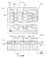
本発明の実施の一形態を図1ないし図5を参照して以下に説明する。図1に示すように、本形態のインクジェットヘッド100は、フルカラー印刷に対応した往復タイプに形成されており、各々が副走査方向に配列された多数のインクノズル101からなる10列のノズルアレイ102が主走査方向に配列されている。
【0011】
より詳細には、本形態のインクジェットヘッド100では、10列のノズルアレイ102が、三原色であるYMC色のインク滴D−Y,M,Cを個々に吐出するノズルアレイ102−Y,M,Cからなり、これらYMC用のノズルアレイ102−Y,M,CがY用を中心に主走査方向で対象に配列されている。
【0012】
さらに、本形態のインクジェットヘッド100では、10列のノズルアレイ102が、所定の第1液量のインク滴D−Lを吐出する複数の第1のノズルアレイ102−Lと、第1液量より少量の第2液量のインク滴D−Sを吐出する複数の第2のノズルアレイ102−Sからなる。
【0013】
例えば、インク滴D−Lの第1液量は“5(pl:pico-liter)”からなり、インク滴D−Sの第2液量は“2(pl)”からなる。なお、これより以下では説明を簡単とするため、第1液量を“多量”と呼称するとともに第2液量を“少量”と呼称する。
【0014】
より具体的には、そのC用およびM用のノズルアレイ102−C,Mは、第1のノズルアレイ102−CL,MLと第2のノズルアレイ102−CS,MSからなるが、Y用のノズルアレイ102−Yは、第1のノズルアレイ102−YLのみからなる。
【0015】
このようなノズルアレイ102が前述のようにY用を中心に主走査方向で対象に配列されているので、本形態のインクジェットヘッド100は、主走査方向の一方から他方まで、ノズルアレイ102−CL▲1▼,CS▲1▼,ML▲1▼,MS▲1▼,YL▲1▼,YL▲2▼,MS▲2▼,ML▲2▼,CS▲2▼,CL▲2▼、が順番に配列されている。
【0016】
このため、本形態のインクジェットヘッド100では、移動方向である主走査方向の少なくとも第1列目に第1のノズルアレイ102−Lが位置するとともに、第2列目に第2のノズルアレイ102−Sが位置している。なお、多量のインク滴D−Lを吐出するインクノズル101−Lは、例えば、直径“16(μm)”の円形に形成されており、少量のインク滴D−Sを吐出するインクノズル101−Sは、例えば、直径“10(μm)”の円形に形成されている。
【0017】
また、YMC用のノズルアレイ102−Y,M,Cは主走査方向で対称に配列されているが、そのインク滴Dが同色で同径の(図中)左側と右側とのノズルアレイ102−▲1▼,▲2▼では、インクノズル101の配列の周期“T”が同一で位相が半周期分“t(=T/2)”だけ相反している。
【0018】
なお、ノズルアレイ102−Y,M,Cにおいて、MC用については多量/少量のインク滴D−L,Sを吐出する第1/第2のノズルアレイ102−L,Sを形成しているが、Y用については多量のインク滴D−Lを吐出する第1のノズルアレイ102−Lのみ形成している。
【0019】
このため、濃淡で画像を形成するときに比べて、液滴の打ち込み量を低減することができる。特に少量の滴量を1(pl)以下とすることにより、液滴量の違いが最も画質に影響を及ぼしやすい場合であっても、濃淡使用時と同等の画質を達成することができる。
【0020】
なお、本形態のインクジェットヘッド100では、各ノズルアレイ102にインクノズル101が“600(dpi:dot per inch)”の密度で配列されているので、各ノズルアレイ102でのインクノズル101の配列の周期“T”は約“42(μm)”となっている。
【0021】
また、本形態のインクジェットヘッド100では、第1のノズルアレイ102−Lの配列ピッチおよび第2のノズルアレイ102−Sの配列ピッチは“1.376(mm)”であり、隣接する同色のノズルアレイ102の配列ピッチは“0.254(mm)”である。この時、隣接する同色の第1のノズルアレイ102−Lおよび第2のノズルアレイ102−S間にはインク供給口111が配置されている。
【0022】
つまり、同一インク供給口111に対応する多量ノズル101-Lと少量ノズル101-Sは主走査方向に対し、周期約“21(μm)”で千鳥配列されている。また、第2のノズルアレイ102-Sの少量ノズル101−Sは主走査方向の両方向において多量ノズル101-Lに挟まれるように配置されている。
【0023】
本形態のインクジェットヘッド100は、図2(b)に示すように、オリフィスプレート104とシリコン基板105とを有しており、これらが積層されている。インクノズル101はオリフィスプレート104に形成されており、隣接する同色のノズルアレイ102ごとにオリフィスプレート104の内部で一体に連通されている。
【0024】
シリコン基板105は、例えば、〈100〉シリコンからなり、図2(a)に示すように、その表面にはインクノズル101の位置ごとにインク吐出手段である発熱素子107が形成されている。この発熱素子107がインクを発泡させることにより、インクノズル101からインク滴Dが吐出される。
【0025】
ただし、前述のようにインクノズル101には大小があるので、大径のインクノズル101−Lに対応した位置には“26×26(μm)”の第1面積の第1発熱素子107−Lが形成されており、小径のインクノズル101−Sに対応した位置には“22×22(μm)”の第2面積の第2発熱素子107−Sが形成されている。
【0026】
これらの発熱素子107に主走査方向で隣接する位置には駆動回路108が形成されており、この駆動回路108に隣接する発熱素子107が結線されている。また、シリコン基板105の表面の副走査方向の両端近傍の位置には、多数の接続端子109が形成されており、その接続端子109に駆動回路108が結線されている。
【0027】
シリコン基板105には、隣接する同色のノズルアレイ102ごとにインク供給路111が形成されているので、図2(b)に示すように、このインク供給路111は隣接する同色のノズルアレイ102に共通に連通している。なお、このインク供給路111は、〈100〉シリコンからなるシリコン基板105に異方性エッチングにより形成されているので、その断面形状は台形となっている。
【0028】
図3ないし図5に示すように、本形態のインクジェットヘッド100はインクジェットプリンタ200の一部として形成されており、図4および図5に示すように、本形態のインクジェットプリンタ200のキャリッジ201に搭載されている。
【0029】
より詳細には、図3に示すように、本形態のインクジェットヘッド100はヘッド本体202に装着されており、図5に示すように、このヘッド本体202がキャリッジ201に装着されている。キャリッジ201には、YMC用のインクカートリッジ202−Y,M,Cが着脱自在に装着され、これらのインクカートリッジ202−Y,M,CからYMC色のインクがインクジェットヘッド100のYMC用のノズルアレイ102−Y,M,Cに各々供給される。
【0030】
また、図4に示すように、本形態のインクジェットプリンタ200は、主走査機構204と副走査機構205とを有しており、主走査機構204は、キャリッジ201を主走査方向に移動自在に支持しており、副走査機構205は、インクジェットヘッド100と対向する位置で被プリント媒体Pを副走査方向に移動させる。
【0031】
さらに、本形態のインクジェットプリンタ200は、マイクロコンピュータやドライバ回路などからなる統合制御回路を有しており(図示せず)、この統合制御回路により、インクジェットヘッド100、主走査機構204、副走査機構205、の動作を統合制御する。
【0032】
上述のような構成において、本形態のインクジェットプリンタ200は、被プリント媒体Pの表面にカラー画像を形成することができる。その場合、副走査機構205により被プリント媒体Pを副走査方向に移動させるとともに、主走査機構204によりインクジェットヘッド100を主走査方向に往復移動させる。このとき、インクジェットヘッド100のインクノズル101から被プリント媒体Pにインク滴Dを吐出させるので、このインク滴Dが被プリント媒体Pに付着することでドットマトリクスのカラー画像が形成される。
【0033】
本形態のインクジェットプリンタ200は、複数の動作モードが切換自在に設定され、その動作モードに対応して各種の印刷動作が実行される。例えば、その基本モードである高画質(低速)モードでは、インクジェット100が主走査方向に往復移動されるとき、その往路と復路との両方で全部のノズルアレイ102が稼働される。また、低画質(高速)モードでは、インクジェット100が主走査方向に往復移動されるとき、その往路と復路との両方で第1のノズルアレイ102−Lのみが稼働される。
【0034】
本形態のインクジェットヘッド100は、図1に示すように、前述のようにインク滴Dが同色で同径の左側と右側とのノズルアレイ102−▲1▼,▲2▼では、インクノズル101の配列の周期“T”が同一で位相が半周期分“t”だけ相反している。このため、上述のように全部のノズルアレイ102を同時に稼働させることで、インク滴Dによる画素を被プリント媒体Pに副走査方向に周期“t”で配列することができる。
【0035】
さらに、本形態のインクジェットプリンタ200は、YMC色の画素の密度を調節することで二次色を疑似的に形成するが、本形態のインクジェットヘッド100は、M色とC色とは多量のインク滴D−Lと少量のインク滴D−Sとを選択的に吐出させる。このため、M色とC色との大小の画素を自在に形成できるので、疑似的に形成する二次色の画素の密度を向上させることができる。
【0036】
この時、多量のインク滴D−Lおよび少量のインク滴D−Sの被プリント媒体P上でのドット径平均はそれぞれ約“48(μm)”以内、および、約“36(μm)”以内である。なお、Y色は多量のインク滴D−Lしか吐出しないが、Y色は被プリント媒体Pの白色に近いため、大小の画素を形成する必要性が低い。
【0037】
ちなみに、画素視認性の観点からドット径は約“20(μm)”が下限に達するので、さらなる高画質を実現する際には、小量のインク滴D-Sで約“20(μm)”のドット径を実現することが好適である。このドット径を実現するためには、にじみ率約“2%”の紙面上に打ち込まれたと仮定すると、インク滴の吐出量は約“0.5(pl)”が適当である。また、少量のインク滴D-Sと多量のインク滴D-Lの組み合わせとしては、大量は小量の2倍以上の整数倍であることが、高階調を達成する上で好ましい。
【0038】
前述のように、複数の動作モードのうち低画質(高速)モードでは、インクジェット100が主走査方向に往復移動されるとき、その往路と復路との両方で第1のノズルアレイ102−Lのみが稼働される。この場合、複数の第1のノズルアレイ102−Lの各々はお互いのそのインク滴Dの移動方向の気流による干渉を受けないようにノズルアレイ間隔を広くとることが好ましい。つまり、同一インク供給口111に対応する第1のノズルアレイ102-Lと第2のノズルアレイ102-Sの配置順としては、主走査方向先頭側に第1のノズルアレイ102-Lを有する本形態は好ましい。
【0039】
ここで、気流の影響について図6を用いて説明する。まず、本形態のインクジェットヘッド100では、前述のように、主走査方向において複数の第2のノズルアレイ102−Sの各々の両側に第1のノズルアレイ102−Lが位置する構成となっている。
【0040】
このような構成では、図6に示すように、少量のインク滴D−Sの両側に多量のインク滴D−Lによる気流が発生する。この気流は、少量のインク滴D−Sの着弾精度に影響を与えるが、少量のインクノズル101−Sの片側だけに多量のインクノズル101−Lがあった場合に比べ、両側にあると、少量のインク滴D−Sに両側の気流が均等に作用する。このため、少量のインク滴D−Sの飛翔方向が片寄ることがなく、その着弾精度が向上するので画質も良好となる。
【0041】
また、少量のインク滴D−Sの吐出では、多量のインク滴D−Lの吐出に比べて主滴に対するミスト量が相対的に多量となる傾向があるが、この少量のインク滴D−Sの吐出に発生した浮遊ミストを、多量のインク滴D−Lの吐出による気流でヘッド側に移動させることも不可能ではない。
【0042】
本実施の形態のインクジェットヘッド100では、全部の第2のノズルアレイ102−Sの両側に第1のノズルアレイ102−Lが配置されているので、高画質のプリントが可能となっている。
【0043】
しかも、本形態のインクジェットヘッド100は、カラー画像を形成するときに多量のインク滴D−Lと少量のインク滴D−Sとを選択的に使用するので、形成する画像の二次色の画素の密度を向上させることができ、その画質が良好である。それでいて、画質への影響が少ないY色のためには第1のノズルアレイ102−YL▲1▼,YL▲2▼しか形成していないので、その構造が簡単で小型軽量化および生産性向上が実現されている。
【0044】
さらに、本形態のインクジェットヘッド100は、同色のノズルアレイ102が2列ずつ配列されているが、その2列の同色のノズルアレイ102の各々には一つのインク供給路111が共通に連通している。このため、インク供給路111の個数が削減されており、インクジェットヘッド100の構造が簡単で生産性が向上している。
【0045】
[実施の形態の変形例]
本発明は上記形態に限定されるものではなく、その要旨を逸脱しない範囲で各種の変形を許容する。例えば、上記形態では画質への影響が少ないY色のためには第1のノズルアレイ102−YL▲1▼,YL▲2▼しか形成していないことにより、インクジェットヘッド100の構造を簡略化することを例示したが、図7に例示するインクジェットヘッド120のように、YMC用の全部に第1のノズルアレイ102−L▲1▼,L▲2▼と第2のノズルアレイ102−S▲1▼,S▲2▼を形成することも可能である。
【0046】
また、上記形態ではインクジェットヘッド100にYMC用のノズルアレイ102が形成されていることを例示したが、さらにK(blacK)用のノズルアレイ102を追加することも可能であり、YMC以外の色用のノズルアレイ102を形成することも可能である(ともに図示せず)。
【0047】
同様に、上記形態ではインクジェットプリンタ200のYMC用のインクジェットヘッド100のみ搭載することを例示したが、さらにK用のインクジェットヘッドを搭載することも可能であり、YMC以外の色用のインクジェットヘッドを搭載することも可能である(ともに図示せず)。
【0048】
さらに、上記形態ではインクジェットプリンタ200がインクジェットヘッド100を主走査方向に往復移動させるときに全部のノズルアレイ102を常時稼働させることを例示したが、例えば、図1でインクジェットヘッド100が右側に移動するときには右側のノズルアレイ102−▲1▼のみ稼働させ、左側に移動するときには左側のノズルアレイ102−▲2▼のみ稼働させるようなことも可能である。
【0049】
また、上記形態ではインクジェットヘッド100に主走査方向で対象にノズルアレイ102を配列し、インクジェットヘッド100を主走査方向の往復移動の両方で稼働させることを例示したが、例えば、図1の右半分の構造のインクジェットヘッド(図示せず)なども実施可能である。
【0050】
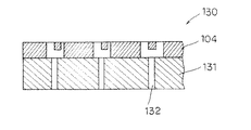
さらに、上記形態では〈100〉シリコンからなるシリコン基板105に異方性エッチングによりインク供給路111を形成することで、その断面形状が台形となっていることを例示した。しかし、図8に例示するインクジェットヘッド130のように、〈110〉シリコンからなるシリコン基板131に異方性エッチングによりインク供給路132を形成することで、その断面形状を直線状とすることも可能である。また、インク供給路を異方性エッチングでなくレーザ加工やサンドブラストで形成することで、シリコン基板の面方位に関係なくインク供給路を直線状に形成することも可能である。
【0051】
さらに、上記形態では大小のインク滴Dを吐出させるために大小のインクノズル102−L,Sと大小の発熱素子107−L,Sとを組み合わせることを例示したが、例えば、一定サイズのインクノズル102に大小の発熱素子107−L,Sを組み合わせることや、大小のインクノズル102に一定サイズの発熱素子107を組み合わせることも不可能ではない。
【0052】
また、上記形態ではインクノズル101からインク滴Dを吐出させるインク吐出手段として発熱素子107を例示したが、これを振動素子(図示せず)とすることも可能である。さらに、上記形態では各種の数値を具体的に例示したが、当然ながら例示した数値は各種に変更可能である。
【0053】
【発明の効果】
本発明のインクジェットヘッドでは、主走査方向において第2のノズルアレイの両側に第1のノズルアレイが配置されていることにより、気流によるインク滴の吐出方向の偏向を全体的に平均的に低減することができ、複数のノズルアレイから吐出されるインク滴の着弾位置の相対変位を削減して印刷画像の画質を向上させることができる。
【図面の簡単な説明】
【図1】本発明の実施の形態のインクジェットヘッドのインクノズルのパターンを示す平面図である。
【図2】インクジェットヘッドの内部構造を示し、(a)はシリコン基板の平面図、(b)はインクジェットヘッドの縦断正面図、である。
【図3】インクジェットヘッドがヘッド本体に装着された状態を示す斜視図である。
【図4】本発明の実施の形態のインクジェットプリンタの内部構造を示す斜視図である。
【図5】キャリッジにインクカートリッジを装着する状態を示す分解斜視図である。
【図6】インクミストを旋回気流により回収している状態を示す模式図である。
【図7】第1の変形例のインクジェットヘッドのインクノズルのパターンを示す平面図である。
【図8】第2の変形例のインクジェットヘッドの内部構造を示す縦断正面図である。
【符号の説明】
100,120,130 インクジェットヘッド
101 インクノズル
102 ノズルアレイ
104 オリフィスプレート
105,131 シリコン基板
107 発熱素子
111,132 インク供給路
200 インクジェットプリンタ
204 主走査機構
205 副走査機構
D インク滴
P 被プリント媒体[0001]
BACKGROUND OF THE INVENTION
The present invention relates to an inkjet head of an inkjet printer, and more particularly to an inkjet head in which a large number of ink nozzles are arranged in a sub-scanning direction in each of a plurality of nozzle arrays arranged in a main scanning direction.
[0002]
[Prior art]
In recent years, inkjet printers have been widely used as printer devices, and there is a demand for higher printing speed and higher image quality. In general inkjet printers, the inkjet head is moved in the main scanning direction and the printing medium such as printing paper is moved in the sub-scanning direction, and a dot matrix image is formed on the printing medium with ink droplets ejected from the inkjet head. (See, for example, Patent Document 1).
[0003]
[Patent Document 1]
JP 2001-171119 A
[Problems to be solved by the invention]
A general inkjet head has a large number of ink nozzles arranged in a sub-scanning direction in a nozzle array, and a full-color inkjet head has a nozzle array of first to third primary colors that individually ejects ink droplets of three primary colors. Are juxtaposed in the main scanning direction.
[0005]
By doing so, the ink-jet head can form a high-resolution color image with good color development at a high speed. However, there is a demand for higher image quality at present. Therefore, as a means for improving the printing quality, there is a case where the ink nozzle is reduced in diameter to reduce the amount of ink droplets.
[0006]
However, in this case, unless a large number of ink nozzles are arranged at high density, the printing speed is lowered, which is not preferable. It has also been proposed to perform high-quality printing at high speed by changing the amount of ink droplets with the same ink nozzle, but this is actually difficult.
[0007]
Therefore, the present inventor has proposed that the print quality can be improved without decreasing the printing speed by separately providing an ink nozzle for ejecting a large amount of ink droplets and an ink nozzle for ejecting a small amount of ink droplets. However, when the discharge amount of a small amount of ink droplets is about 2 (pl: pico-liter), the impact is likely to be affected by the air current and the landing accuracy tends to be deteriorated.
[0008]
The present invention has been made in view of the above-described problems, and devise the arrangement of ink nozzles that eject a large amount of ink droplets and ink nozzles that eject a small amount of ink droplets in consideration of the influence of airflow. Accordingly, an object of the present invention is to provide an ink jet head capable of improving the landing accuracy of a small amount of ink droplets and forming a high quality image.
[0009]
[Means for Solving the Problems]
The inkjet head of the present invention includes a first nozzle array in which ink nozzles that eject ink droplets of a predetermined first liquid amount are arranged in the sub-scanning direction, and a second liquid amount ink that is smaller than the first liquid amount. A second nozzle array in which ink nozzles for ejecting droplets are arranged in the sub-scanning direction, and a plurality of nozzle arrays that are arranged in the main scanning direction and facing a print medium that is moved in the sub-scanning direction in being moved in the main scanning direction, each of said an inkjet head for ejecting ink droplets onto the print medium, a plurality of the second nozzle array from any ink nozzles when it is moved in the main scanning direction The first nozzle array is adjacent to both sides of the main scanning direction. Therefore, in the inkjet head of the present invention, when ink droplets are ejected simultaneously in parallel from a plurality of nozzle arrays, an airflow is generated in the ejection direction, but the airflow due to a large amount of ink droplets is offset by a small amount of ink droplets. There is nothing to do.
[0010]
DETAILED DESCRIPTION OF THE INVENTION
[Configuration of the embodiment]
An embodiment of the present invention will be described below with reference to FIGS. As shown in FIG. 1, the
[0011]
More specifically, in the
[0012]
Furthermore, in the
[0013]
For example, the first liquid amount of the ink droplets DL is “5 (pl: pico-liter)”, and the second liquid amount of the ink droplets DS is “2 (pl)”. Hereinafter, in order to simplify the description, the first liquid amount is referred to as “large amount” and the second liquid amount is referred to as “small amount”.
[0014]
More specifically, the nozzle array 102-C, M for C and M includes the first nozzle array 102-CL, ML and the second nozzle array 102-CS, MS, The nozzle array 102-Y includes only the first nozzle array 102-YL.
[0015]
As described above, since the
[0016]
For this reason, in the
[0017]
The YMC nozzle arrays 102-Y, M, and C are arranged symmetrically in the main scanning direction, but the ink droplets D have the same color and the same diameter (in the drawing), the left and right nozzle arrays 102-. In {circle around (1)} and {circle around (2)}, the period “T” of the arrangement of the
[0018]
In the nozzle arrays 102-Y, M, and C, the first and second nozzle arrays 102-L and S that discharge a large amount / small amount of ink droplets DL and S are formed for the MC. For Y, only the first nozzle array 102-L that discharges a large amount of ink droplets DL is formed.
[0019]
For this reason, it is possible to reduce the amount of droplets to be ejected as compared with the case of forming an image with light and shade. In particular, by setting the amount of a small amount of droplets to 1 (pl) or less, even when the difference in the amount of droplets is most likely to affect the image quality, it is possible to achieve the same image quality as when using light and shade.
[0020]
In the
[0021]
In the
[0022]
That is, the large quantity nozzles 101-L and the small quantity nozzles 101-S corresponding to the same
[0023]
As shown in FIG. 2B, the
[0024]
The
[0025]
However, since the
[0026]
A
[0027]
Since the
[0028]
As shown in FIGS. 3 to 5, the
[0029]
More specifically, as shown in FIG. 3, the
[0030]
As shown in FIG. 4, the ink jet printer 200 of this embodiment includes a
[0031]
Furthermore, the ink jet printer 200 according to the present embodiment has an integrated control circuit (not shown) including a microcomputer, a driver circuit, and the like. By this integrated control circuit, the
[0032]
In the configuration as described above, the ink jet printer 200 of the present embodiment can form a color image on the surface of the print medium P. In that case, the print medium P is moved in the sub-scanning direction by the
[0033]
In the inkjet printer 200 of the present embodiment, a plurality of operation modes are set to be switchable, and various printing operations are executed in accordance with the operation modes. For example, in the high image quality (low speed) mode that is the basic mode, when the
[0034]
As shown in FIG. 1, the
[0035]
Furthermore, the ink jet printer 200 of this embodiment forms a secondary color in a pseudo manner by adjusting the density of YMC color pixels, but the
[0036]
At this time, the average dot diameter of the large amount of ink droplets DL and the small amount of ink droplets DS on the print medium P is within about “48 (μm)” and within about “36 (μm)”, respectively. It is. Note that the Y color ejects only a large amount of ink droplets DL, but the Y color is close to the white color of the print medium P, so the necessity of forming large and small pixels is low.
[0037]
By the way, from the viewpoint of pixel visibility, the dot diameter of about “20 (μm)” reaches the lower limit. Therefore, when realizing higher image quality, a small amount of ink droplets DS is about “20 (μm)”. It is preferable to realize a dot diameter of. In order to realize this dot diameter, it is assumed that the ink droplet ejection amount is about “0.5 (pl)”, assuming that the ink is driven on a paper surface with a bleeding rate of about “2%”. Further, as a combination of the small amount of ink droplets DS and the large amount of ink droplets DL, it is preferable that the large amount is an integer multiple of twice or more the small amount in order to achieve high gradation.
[0038]
As described above, in the low image quality (high speed) mode among the plurality of operation modes, when the
[0039]
Here, the influence of the airflow will be described with reference to FIG. First, in the
[0040]
In such a configuration, as shown in FIG. 6, an air flow is generated by a large amount of ink droplets DL on both sides of the small amount of ink droplets DS. This air flow affects the landing accuracy of a small amount of ink droplets DS, but when there are a large amount of ink nozzles 101-L only on one side of a small amount of ink nozzles 101-S, Airflow on both sides acts evenly on a small amount of ink droplets DS. For this reason, the flying direction of a small amount of ink droplets DS does not deviate, and the landing accuracy is improved, so that the image quality is also improved.
[0041]
Further, in the ejection of a small amount of ink droplets DS, the amount of mist with respect to the main droplet tends to be relatively large compared to the ejection of a large amount of ink droplets DL, but this small amount of ink droplets DS. It is not impossible to move the floating mist generated in the discharge to the head side by the air flow generated by the discharge of a large amount of ink droplets DL.
[0042]
In the
[0043]
In addition, since the
[0044]
Further, in the
[0045]
[Modification of Embodiment]
The present invention is not limited to the above embodiment, and various modifications are allowed without departing from the scope of the present invention. For example, the structure of the
[0046]
In the above embodiment, the
[0047]
Similarly, in the above embodiment, it is exemplified that only the
[0048]
Further, in the above embodiment, it is exemplified that the
[0049]
In the above embodiment, the
[0050]
Furthermore, in the said form, it illustrated that the cross-sectional shape became trapezoid by forming the
[0051]
Further, in the above embodiment, the combination of the large and small ink nozzles 102-L and S and the large and small heat generating elements 107-L and S in order to discharge the large and small ink droplets D is exemplified. It is not impossible to combine the large and small heating elements 107 -L and S with 102, or to combine the large and
[0052]
In the above embodiment, the
[0053]
【The invention's effect】
In the inkjet head of the present invention, the first nozzle array is arranged on both sides of the second nozzle array in the main scanning direction, so that the deflection of the ink droplet ejection direction due to the airflow is reduced overall on average. In addition, the relative displacement of the landing positions of the ink droplets ejected from the plurality of nozzle arrays can be reduced, and the quality of the printed image can be improved.
[Brief description of the drawings]
FIG. 1 is a plan view showing a pattern of ink nozzles of an ink jet head according to an embodiment of the present invention.
2A is a plan view of a silicon substrate, and FIG. 2B is a longitudinal front view of the inkjet head.
FIG. 3 is a perspective view showing a state in which the inkjet head is mounted on the head body.
FIG. 4 is a perspective view showing an internal structure of the ink jet printer according to the embodiment of the present invention.
FIG. 5 is an exploded perspective view illustrating a state where an ink cartridge is mounted on a carriage.
FIG. 6 is a schematic diagram showing a state where ink mist is collected by a swirling airflow.
FIG. 7 is a plan view showing an ink nozzle pattern of an ink jet head according to a first modification.
FIG. 8 is a longitudinal front view showing an internal structure of an ink jet head according to a second modification.
[Explanation of symbols]
100, 120, 130
Claims (7)
前記副走査方向に移動される被プリント媒体と対向する位置で前記主走査方向に移動され、前記主走査方向に移動されるときに任意のインクノズルから前記被プリント媒体にインク滴を吐出するインクジェットヘッドであって、
複数の前記第2のノズルアレイの各々の前記主走査方向の両側に前記第1のノズルアレイが隣接していることを特徴とするインクジェットヘッド。A first nozzle array in which ink nozzles that eject ink droplets of a predetermined first liquid amount are arranged in the sub-scanning direction; and an ink nozzle that ejects ink droplets of a second liquid amount smaller than the first liquid amount. A plurality of second nozzle arrays arranged in the sub-scanning direction, and a plurality of nozzle arrays arranged in the main scanning direction,
Ink jet that is moved in the main scanning direction at a position facing the print medium moved in the sub-scanning direction, and ejects ink droplets from any ink nozzle to the print medium when moved in the main scanning direction. Head,
The inkjet head, wherein the first nozzle array is adjacent to both sides in the main scanning direction of each of the plurality of second nozzle arrays.
前記インクジェットヘッドと対向する位置で前記印刷用紙を副走査方向に移動させる副走査機構と、
前記インクジェットヘッドと前記主走査機構と前記副走査機構との動作を統合制御する統合制御回路と、
を有しているインクジェットプリンタ。An ink jet head according to any one of claims 1 to 6, a main scanning mechanism for moving the ink jet head in a main scanning direction,
A sub-scanning mechanism for moving the printing paper in a sub-scanning direction at a position facing the inkjet head;
An integrated control circuit that integrally controls operations of the inkjet head, the main scanning mechanism, and the sub-scanning mechanism;
Inkjet printer having.
Priority Applications (7)
| Application Number | Priority Date | Filing Date | Title |
|---|---|---|---|
| JP2003114516A JP4236251B2 (en) | 2002-04-23 | 2003-04-18 | Inkjet head |
| US10/419,140 US6976748B2 (en) | 2002-04-23 | 2003-04-21 | Ink jet head and printer |
| KR10-2003-0025350A KR100524571B1 (en) | 2002-04-23 | 2003-04-22 | Ink jet head and printer |
| EP03009165A EP1356940B1 (en) | 2002-04-23 | 2003-04-22 | Ink jet head and printer |
| DE60331180T DE60331180D1 (en) | 2002-04-23 | 2003-04-22 | Inkjet head and printer |
| TW092109488A TW579335B (en) | 2002-04-23 | 2003-04-23 | Ink jet head and printer |
| CNB031222250A CN100496982C (en) | 2002-04-23 | 2003-04-23 | Ink jet head and ink jet printing machine |
Applications Claiming Priority (2)
| Application Number | Priority Date | Filing Date | Title |
|---|---|---|---|
| JP2002121205 | 2002-04-23 | ||
| JP2003114516A JP4236251B2 (en) | 2002-04-23 | 2003-04-18 | Inkjet head |
Publications (3)
| Publication Number | Publication Date |
|---|---|
| JP2004001491A JP2004001491A (en) | 2004-01-08 |
| JP2004001491A5 JP2004001491A5 (en) | 2006-06-08 |
| JP4236251B2 true JP4236251B2 (en) | 2009-03-11 |
Family
ID=28793615
Family Applications (1)
| Application Number | Title | Priority Date | Filing Date |
|---|---|---|---|
| JP2003114516A Expired - Fee Related JP4236251B2 (en) | 2002-04-23 | 2003-04-18 | Inkjet head |
Country Status (7)
| Country | Link |
|---|---|
| US (1) | US6976748B2 (en) |
| EP (1) | EP1356940B1 (en) |
| JP (1) | JP4236251B2 (en) |
| KR (1) | KR100524571B1 (en) |
| CN (1) | CN100496982C (en) |
| DE (1) | DE60331180D1 (en) |
| TW (1) | TW579335B (en) |
Families Citing this family (34)
| Publication number | Priority date | Publication date | Assignee | Title |
|---|---|---|---|---|
| JP4353526B2 (en) * | 2003-12-18 | 2009-10-28 | キヤノン株式会社 | Element base of recording head and recording head having the element base |
| US7249815B2 (en) | 2004-01-30 | 2007-07-31 | Hewlett-Packard Development Company, L.P. | Nozzle distribution |
| JP4115465B2 (en) * | 2004-06-02 | 2008-07-09 | キヤノン株式会社 | Ink jet recording head, ink jet cartridge including ink jet recording head, and ink jet recording apparatus |
| JP4125271B2 (en) * | 2004-08-18 | 2008-07-30 | キヤノン株式会社 | Data processing apparatus, data processing method, ink jet recording apparatus, ink jet recording method, and program |
| JP4632421B2 (en) * | 2004-12-07 | 2011-02-16 | キヤノン株式会社 | Inkjet recording head |
| JP4553360B2 (en) * | 2004-12-24 | 2010-09-29 | キヤノン株式会社 | Inkjet recording head |
| JP5049465B2 (en) | 2005-02-21 | 2012-10-17 | キヤノン株式会社 | Recording apparatus and recording head |
| US7867561B2 (en) * | 2005-06-22 | 2011-01-11 | Canon Kabushiki Kaisha | Circuit pattern forming method and circuit pattern forming device |
| JP4724490B2 (en) * | 2005-08-09 | 2011-07-13 | キヤノン株式会社 | Liquid discharge head |
| JP2007062272A (en) * | 2005-09-01 | 2007-03-15 | Canon Inc | Liquid discharge head |
| JP4701969B2 (en) * | 2005-09-29 | 2011-06-15 | ブラザー工業株式会社 | Inkjet head and inkjet recording apparatus |
| DE602006017947D1 (en) * | 2005-09-30 | 2010-12-16 | Brother Ind Ltd | Method for producing a nozzle plate and method for producing a liquid drop device |
| US7845765B2 (en) * | 2005-10-11 | 2010-12-07 | Silverbrook Research Pty Ltd | Inkjet printers with elongate chambers, nozzles and heaters |
| US7712876B2 (en) * | 2005-10-11 | 2010-05-11 | Silverbrook Research Pty Ltd | Inkjet printhead with opposing actuator electrode polarities |
| JP4298697B2 (en) * | 2005-11-25 | 2009-07-22 | キヤノン株式会社 | Ink jet recording head, ink jet cartridge including ink jet recording head, and ink jet recording apparatus |
| US7401883B2 (en) * | 2006-01-26 | 2008-07-22 | Seiko Epson Corporation | Printing method and printing apparatus |
| JP4856982B2 (en) * | 2006-03-02 | 2012-01-18 | キヤノン株式会社 | Inkjet recording head |
| JP2008018556A (en) * | 2006-07-11 | 2008-01-31 | Canon Inc | Inkjet recording head |
| JP5230084B2 (en) * | 2006-08-07 | 2013-07-10 | キヤノン株式会社 | Inkjet recording head |
| JP5037903B2 (en) | 2006-11-09 | 2012-10-03 | キヤノン株式会社 | Inkjet recording head and inkjet recording apparatus |
| JP5008443B2 (en) * | 2007-04-11 | 2012-08-22 | キヤノン株式会社 | Ink jet recording head and ink jet recording cartridge |
| US7984967B2 (en) * | 2007-04-13 | 2011-07-26 | Canon Kabushiki Kaisha | Ink jet head |
| US7735962B2 (en) | 2007-08-31 | 2010-06-15 | Canon Kabushiki Kaisha | Ink jet print head |
| US20090059248A1 (en) * | 2007-09-03 | 2009-03-05 | Canon Kabushiki Kaisha | Inkjet printing apparatus and processing method therefor |
| JP5157680B2 (en) * | 2007-09-18 | 2013-03-06 | セイコーエプソン株式会社 | Liquid ejection apparatus and image forming method |
| JP2009137173A (en) * | 2007-12-06 | 2009-06-25 | Canon Inc | Liquid discharge head and recording device |
| JP2009154376A (en) * | 2007-12-26 | 2009-07-16 | Canon Inc | Ink-jet recording head and ink-jet recording device |
| JP5183357B2 (en) | 2008-08-21 | 2013-04-17 | キヤノン株式会社 | Inkjet recording head |
| JP5393407B2 (en) * | 2008-12-19 | 2014-01-22 | キヤノン株式会社 | Liquid ejection head and recording apparatus |
| JP5202371B2 (en) * | 2009-02-06 | 2013-06-05 | キヤノン株式会社 | Inkjet recording head |
| JP5490128B2 (en) | 2009-09-30 | 2014-05-14 | キヤノン株式会社 | Inkjet head |
| CN103640337A (en) * | 2013-12-11 | 2014-03-19 | 晏石英 | Inkjet printing head |
| JP6459526B2 (en) | 2014-04-24 | 2019-01-30 | セイコーエプソン株式会社 | Liquid ejection device and liquid ejection method |
| CN114683726A (en) * | 2020-12-25 | 2022-07-01 | 深圳市汉森软件有限公司 | Image data packet printing method, device, control board, equipment and storage medium |
Family Cites Families (19)
| Publication number | Priority date | Publication date | Assignee | Title |
|---|---|---|---|---|
| US5208605A (en) | 1991-10-03 | 1993-05-04 | Xerox Corporation | Multi-resolution roofshooter printheads |
| JP3210098B2 (en) | 1992-10-30 | 2001-09-17 | キヤノン株式会社 | Ink jet recording apparatus and ink jet recording method |
| US5412410A (en) * | 1993-01-04 | 1995-05-02 | Xerox Corporation | Ink jet printhead for continuous tone and text printing |
| EP0613781B1 (en) | 1993-02-26 | 1997-05-02 | Canon Kabushiki Kaisha | Ink jet printing head, ink jet head cartridge and printing apparatus |
| JPH09164706A (en) | 1995-12-15 | 1997-06-24 | Ricoh Co Ltd | Ink jet head |
| JPH10166576A (en) * | 1996-12-12 | 1998-06-23 | Minolta Co Ltd | Ink jet recording head, and ink jet recording device |
| JPH10166567A (en) | 1996-12-12 | 1998-06-23 | Minolta Co Ltd | Ink jet recorder |
| JP3408130B2 (en) | 1997-12-19 | 2003-05-19 | キヤノン株式会社 | Ink jet recording head and method of manufacturing the same |
| JPH11179920A (en) | 1997-12-24 | 1999-07-06 | Minolta Co Ltd | Ink jet head |
| JP2000006442A (en) | 1998-06-24 | 2000-01-11 | Toppan Printing Co Ltd | Ink jet recording apparatus and recording method using the same |
| JP2001063029A (en) | 1999-06-25 | 2001-03-13 | Matsushita Electric Ind Co Ltd | Ink jet recorder |
| JP2001171119A (en) | 1999-12-22 | 2001-06-26 | Canon Inc | Liquid ejection recording head |
| EP1172214B1 (en) | 2000-07-10 | 2007-01-17 | Canon Kabushiki Kaisha | Liquid ejection recording head and liquid ejection type recording device |
| US6575560B2 (en) | 2000-07-10 | 2003-06-10 | Canon Kabushiki Kaisha | Liquid discharge recording head and liquid discharge recording apparatus |
| JP4532705B2 (en) | 2000-09-06 | 2010-08-25 | キヤノン株式会社 | Inkjet recording head |
| JP2002086732A (en) | 2000-09-12 | 2002-03-26 | Canon Inc | Ink jet recording head, ink jet recorder and electronic device |
| ES2262604T3 (en) * | 2000-11-23 | 2006-12-01 | Oce-Technologies B.V. | METHOD AND PRINTER TO PRINT IN COLORS WITH INK JET. |
| EP1228876B1 (en) * | 2001-01-31 | 2008-01-16 | Canon Kabushiki Kaisha | Liquid ejecting head, suction recovering method, head cartridge and image forming apparatus |
| US6595622B2 (en) * | 2001-03-29 | 2003-07-22 | Fuji Photo Film Co., Ltd. | Ink jet printhead with thick substrate providing reduced warpage |
-
2003
- 2003-04-18 JP JP2003114516A patent/JP4236251B2/en not_active Expired - Fee Related
- 2003-04-21 US US10/419,140 patent/US6976748B2/en not_active Expired - Lifetime
- 2003-04-22 DE DE60331180T patent/DE60331180D1/en not_active Expired - Lifetime
- 2003-04-22 KR KR10-2003-0025350A patent/KR100524571B1/en active IP Right Grant
- 2003-04-22 EP EP03009165A patent/EP1356940B1/en not_active Expired - Lifetime
- 2003-04-23 CN CNB031222250A patent/CN100496982C/en not_active Expired - Fee Related
- 2003-04-23 TW TW092109488A patent/TW579335B/en not_active IP Right Cessation
Also Published As
| Publication number | Publication date |
|---|---|
| TW200307608A (en) | 2003-12-16 |
| US20040021731A1 (en) | 2004-02-05 |
| EP1356940A3 (en) | 2004-01-02 |
| KR20030084660A (en) | 2003-11-01 |
| EP1356940A2 (en) | 2003-10-29 |
| EP1356940B1 (en) | 2010-02-03 |
| US6976748B2 (en) | 2005-12-20 |
| CN100496982C (en) | 2009-06-10 |
| CN1453130A (en) | 2003-11-05 |
| JP2004001491A (en) | 2004-01-08 |
| TW579335B (en) | 2004-03-11 |
| KR100524571B1 (en) | 2005-11-01 |
| DE60331180D1 (en) | 2010-03-25 |
Similar Documents
| Publication | Publication Date | Title |
|---|---|---|
| JP4236251B2 (en) | Inkjet head | |
| US8087759B2 (en) | Print head with offset ejection ports | |
| JP4236250B2 (en) | Inkjet head | |
| CN109203696A (en) | A kind of inkjet-printing device and Method of printing | |
| JP3894548B2 (en) | Liquid discharge head, and head cartridge and image forming apparatus using the liquid discharge head | |
| EP1464495B1 (en) | Fluid ejection device | |
| JP3826084B2 (en) | Liquid discharge head and image forming apparatus using the same | |
| JP2003311962A (en) | Liquid ejection head, head cartridge employing the liquid ejection head, and imaging apparatus | |
| JPH08258291A (en) | Method and apparatus for positioning dot in printer of mixedresolution | |
| US8342647B2 (en) | Inkjet printing apparatus | |
| US20040113975A1 (en) | Color printing with reduced hue shift | |
| JP2016185606A (en) | Liquid discharge head and liquid discharge device | |
| US6848769B2 (en) | Liquid ejecting head having a plurality of groups of ejection openings, and image-forming device using the same | |
| JP4454911B2 (en) | Liquid discharge head and image forming apparatus using the same | |
| US8177328B2 (en) | Ink jet printing apparatus and ink jet printing method | |
| JP3907685B2 (en) | Image forming apparatus | |
| JP4055361B2 (en) | Printing using a print head with a staggered arrangement | |
| JP2005306048A (en) | Print head with staggered arrangement and printing device using it | |
| JPH02266944A (en) | Ink jet head | |
| JPH09239983A (en) | Ink jet recording head, ink jet recording head cartridge and ink jet recording apparatus | |
| JP2003226030A (en) | System for suppressing influence of error aerodynamically occurring in drop-on-demand type print system | |
| JP2003170595A (en) | Method for ejecting liquid, liquid ejecting head and imaging apparatus | |
| JP2707309B2 (en) | Inkjet head | |
| JP2004058525A (en) | Device for forming pattern for correction, computer program, computer system, and pattern for correction |
Legal Events
| Date | Code | Title | Description |
|---|---|---|---|
| A521 | Request for written amendment filed |
Free format text: JAPANESE INTERMEDIATE CODE: A523 Effective date: 20060412 |
|
| A621 | Written request for application examination |
Free format text: JAPANESE INTERMEDIATE CODE: A621 Effective date: 20060412 |
|
| RD03 | Notification of appointment of power of attorney |
Free format text: JAPANESE INTERMEDIATE CODE: A7423 Effective date: 20060412 |
|
| A977 | Report on retrieval |
Free format text: JAPANESE INTERMEDIATE CODE: A971007 Effective date: 20080630 |
|
| A131 | Notification of reasons for refusal |
Free format text: JAPANESE INTERMEDIATE CODE: A131 Effective date: 20080924 |
|
| A521 | Request for written amendment filed |
Free format text: JAPANESE INTERMEDIATE CODE: A523 Effective date: 20081118 |
|
| TRDD | Decision of grant or rejection written | ||
| A01 | Written decision to grant a patent or to grant a registration (utility model) |
Free format text: JAPANESE INTERMEDIATE CODE: A01 Effective date: 20081210 |
|
| A01 | Written decision to grant a patent or to grant a registration (utility model) |
Free format text: JAPANESE INTERMEDIATE CODE: A01 |
|
| A61 | First payment of annual fees (during grant procedure) |
Free format text: JAPANESE INTERMEDIATE CODE: A61 Effective date: 20081215 |
|
| R150 | Certificate of patent or registration of utility model |
Ref document number: 4236251 Country of ref document: JP Free format text: JAPANESE INTERMEDIATE CODE: R150 Free format text: JAPANESE INTERMEDIATE CODE: R150 |
|
| FPAY | Renewal fee payment (event date is renewal date of database) |
Free format text: PAYMENT UNTIL: 20111226 Year of fee payment: 3 |
|
| FPAY | Renewal fee payment (event date is renewal date of database) |
Free format text: PAYMENT UNTIL: 20121226 Year of fee payment: 4 |
|
| FPAY | Renewal fee payment (event date is renewal date of database) |
Free format text: PAYMENT UNTIL: 20131226 Year of fee payment: 5 |
|
| LAPS | Cancellation because of no payment of annual fees |