JP4904790B2 - Combine - Google Patents
Combine Download PDFInfo
- Publication number
- JP4904790B2 JP4904790B2 JP2005345775A JP2005345775A JP4904790B2 JP 4904790 B2 JP4904790 B2 JP 4904790B2 JP 2005345775 A JP2005345775 A JP 2005345775A JP 2005345775 A JP2005345775 A JP 2005345775A JP 4904790 B2 JP4904790 B2 JP 4904790B2
- Authority
- JP
- Japan
- Prior art keywords
- switch
- lever
- adjustment dial
- operation panel
- main transmission
- Prior art date
- Legal status (The legal status is an assumption and is not a legal conclusion. Google has not performed a legal analysis and makes no representation as to the accuracy of the status listed.)
- Expired - Fee Related
Links
Images


Description
本発明は、植立穀稈を収穫するコンバインに関する。 The present invention relates to a combine for harvesting planted cereals.
コンバインはクローラを構成する無限履帯の接地面積を広くし、水田など軟弱な圃場でも自由に走行して刈取作業などの農作業を可能としている。
前記コンバインの操縦席のある運転台には変速レバー、操向レバーなどの各種レバー、各種操作用の操作スイッチ類及び作業内容、車速などを表示する表示装置等が所狭しと配置されている(特許文献1)。
The driver's cab with the combine cockpit is arranged with various levers such as a shift lever and a steering lever, operation switches for various operations, a display device for displaying work contents, a vehicle speed, and the like. Patent Document 1).
上記特許文献1のコンバインの運転台には各種操作レバー、操作スイッチ、操作ダイヤル及び表示パネルなど、コンバインの操縦、刈り取った穀稈の脱穀処理、脱穀した穀粒の一時的貯蔵と外部への排出のための操作用の機器類、表示装置などが操縦席の廻りに配置されている。そのため、運転台のステップに足を載せた状態では、前方下方の刈取装置の分草杆とその周辺を視野に入れるのが難しくなる。そのため植立穀稈を分草する分草杆付近を見ながら刈取作業をするためには立ち姿勢になる必要があった。
本発明の課題は、操縦性を従来より高めた運転台を備えた作業車両を提供することである。
The operation platform of the above-mentioned patent document 1 includes various operation levers, operation switches, operation dials, and display panels, etc., operation of the combine, threshing processing of the harvested cereal, temporary storage of the threshed grain and discharge to the outside Equipment for operation, display devices, etc. are arranged around the cockpit. Therefore, in a state where the foot is placed on the step of the driver's cab, it becomes difficult to view the weed pods and the surrounding area of the cutting device at the front lower side. For this reason, it was necessary to be in a standing position in order to carry out the harvesting work while looking at the vicinity of the weeds that weed the planted cereals.
The subject of this invention is providing the work vehicle provided with the cab which improved maneuverability conventionally.
上記課題は次の解決手段で解決される。
請求項1記載の発明は、ステップ(17)上のサイド側の壁面である側壁部(20)と、該側壁部(20)上に配置した車速を調整するための主変速レバー(14)を含む操作部材設置部と、フロント側壁面である前壁部(19)と、走行速度、燃料量又は作業上の指示内容を含む走行上及び/又は作業上の情報を表示する画面を有するモニタパネル(24)と、旋回方向を含む操作を行う操向レバー(16)と、前壁部(19)と側壁部(20)とに囲まれた領域に設けられる操縦席(8)とを有する運転台(10)を備えたコンバインにおいて、前記運転台(10)の右側面にオペレータの乗降用の空間を設け、前記操向レバー(16)を前壁部(19)の右寄り部分に設け、該操向レバー(16)の後方近傍に操向レバー(16)を操作する時に腕や手を置くための受台(21)を設け、前記モニタパネル(24)と、受台(21)と、オペレータが乗降するときの支えとなるアーム(22a)と、側壁部(20)側の操作パネル(25)とを合成樹脂でブリッジ型に一体成形して前記モニタパネル(24)の下方とステップ(17)の間に操縦席(8)に着座したオペレータの膝が入り込むだけの大きさの空間を設け、前記主変速レバー(14)の前側に操作パネル(25)を配置し、操作パネル(25)には、主変速レバー(14)を中立位置にするとエンジンがアイドリング状態となり、主変速レバー(14)を中立位置から前後方向に動かすとエンジン回転が定格回転まで上がり、籾排出レバーを入り操作するとエンジン回転を定格回転とする第1スイッチ(33)と、上記第1スイッチ(33)が入りのときにエンジン回転数を2600rpmから3000rpmの間で選択する調整ダイヤル(36)と、刈高調整ダイヤル(41)で設定した高さに刈取装置(7)を自動保持するための刈高スイッチ(38)と、車体(2)の左右方向の傾きを維持制御する左右スイッチ(43)と、この車体(2)の傾き度合いを設定する傾き調整ダイヤル(46)とを設け、前記調整ダイヤル(36)と刈高調整ダイヤル(41)と傾き調整ダイヤル(46)は、操作パネル(25)の左側の部位に配置し、前記操向レバー(16)の頂部に設けた第1グリップ部と前傾させた場合の主変速レバー(14)の頂部に設けた第2グリップ部とモニタパネル(24)の上面をほぼ同じ高さに配置し、主変速レバー(14)を操作しながら前記調整ダイヤル(36)と刈高調整ダイヤル(41)と傾き調整ダイヤル(46)が操作可能であり、前記主変速レバー(14)を最高速位置に操作した状態では、該主変速レバー(14)を握った指で操作パネル(25)の各スイッチを操作できるように、前記操作パネル(25)と主変速レバー(14)を配置したことを特徴とするコンバインである。
The above problem is solved by the following means.
The invention according to claim 1 includes a side wall portion (20) which is a side wall surface on the step (17), and a main transmission lever (14) for adjusting a vehicle speed disposed on the side wall portion (20). A monitor panel having a screen for displaying information on traveling and / or work including a traveling speed, a fuel amount, or work instruction content. (24), a steering lever (16) for performing operations including the turning direction, and a driving seat (8) provided in a region surrounded by the front wall portion (19) and the side wall portion (20). In a combine equipped with a platform (10), a space for getting on and off an operator is provided on the right side surface of the cab (10), the steering lever (16) is provided on the right side of the front wall (19), The steering lever (16) is operated near the rear of the steering lever (16). The monitor panel (24), the cradle (21), the arm (22a) that supports the operator when getting on and off, and the side wall ( 20) The operation panel (25) on the side is integrally molded into a bridge shape with a synthetic resin, and the knee of the operator seated on the cockpit (8) enters between the lower side of the monitor panel (24) and the step (17). The operation panel (25) is disposed in front of the main transmission lever (14), and the engine is idling when the main transmission lever (14) is set to the neutral position. When the main shift lever (14) is moved from the neutral position to the front-rear direction, the engine speed increases to the rated speed, and when the saddle discharge lever is operated, the first switch (33) sets the engine speed to the rated speed. When the first switch (33) is turned on, the adjustment dial (36) for selecting the engine speed from 2600 rpm to 3000 rpm and the cutting device (7) at the height set by the cutting height adjustment dial (41) Cutting height switch (38) for automatically holding the vehicle, left / right switch (43) for maintaining and controlling the horizontal inclination of the vehicle body (2), and an inclination adjustment dial (46) for setting the inclination degree of the vehicle body (2) The adjustment dial (36), the cutting height adjustment dial (41), and the inclination adjustment dial (46) are arranged on the left side of the operation panel (25), and the top of the steering lever (16). The top surface of the monitor panel (24) and the second grip portion provided on the top of the main transmission lever (14) when tilted forward with the first grip portion provided on the main transmission lever ( 14) The adjustment dial (36), cutting height adjustment dial (41), and tilt adjustment dial (46) can be operated while operating the main shift lever (14) in the state where the main transmission lever (14) is operated to the highest speed position. The combine is characterized in that the operation panel (25) and the main transmission lever (14) are arranged so that each switch of the operation panel (25) can be operated by a finger holding the transmission lever (14) .
請求項2記載の発明によれば、上記操作パネル(25)に設けたダイヤルのうち、刈高調整ダイヤル(41)と傾き調整ダイヤル(46)を操作パネル(25)の下部に設けたことを特徴とする請求項1記載のコンバインである。 According to the invention described in claim 2, among the dials provided on the operation panel (25), the cutting height adjustment dial (41) and the inclination adjustment dial (46) are provided at the lower part of the operation panel (25). The combine according to claim 1 .
請求項1記載の発明によれば、ステップ(17)に足を載せた状態でオペレータが機体前方に座ることができ、オペレータは、操縦席(8)の前方に身を乗り出して穀稈刈取り作業中に分草杆などの作業車両の先端底部を監視する場合にも前記空間にオペレータの膝が十分入り込むので分草杆を含む刈取装置などの作業車両の先端底部が見易くなるので良好な操縦性のコンバインとなる。 According to the first aspect of the present invention, the operator can sit in front of the fuselage with the foot placed on the step (17), and the operator leans forward in front of the cockpit (8) and performs the grain harvesting operation. Even when monitoring the bottom of the front end of a work vehicle such as a weed weed, the operator's knee is sufficiently inserted into the space, so that it is easy to see the bottom of the front end of the work vehicle such as a cutting device including a weed scissor. It becomes a combine .
また、第1スイッチ(33)を操作パネル(25)に設けたことにより、主変速レバー(14)を中立位置にするとエンジンがアイドリング状態となり、主変速レバー(14)を中立位置から前、後方向に動かすと、それぞれエンジンが定格回転まで上がる操作をし、さらに籾排出レバーを「入り」にするとエンジン回転を定格にする。
さらに、操作パネル(25)のダイヤル群(36,41,46)は左側に配置しているが、主変速レバー(14)を操作しているときにも、これらのダイヤル群(36,41,46)を操作できる。
操向レバー(16)のグリップ高さとモニタパネル(24)の上面とをほぼ同じ高さとすることで、操向レバー(16)の操作中に、モニタパネル(24)の上面に配置した前記スイッチ類の操作がし易くなり、また、主変速レバー(14)のグリップとモニタパネル(24)の上面とをほぼ同じ高さとしているので、主変速レバー(14)を前進方向に倒した時の右横にモニタパネル(24)があることになり、主変速レバー(14)の操作中に、モニタパネル(24)の上面のスイッチ操作がし易くなる。
作業中に主変速レバー(14)の最高速位置で、該レバー(14)をオペレータが握った状態で、指を伸ばすと操作パネル(25)のスイッチを指で操作できる状態となる。
Further, since the first switch (33) is provided on the operation panel (25), when the main transmission lever (14) is set to the neutral position, the engine is in an idling state, and the main transmission lever (14) is moved forward and backward from the neutral position. When moving in the direction, each engine operates to increase the rated speed, and when the soot discharge lever is turned “on”, the engine speed is rated.
Further, although the dial group (36, 41, 46) of the operation panel (25) is arranged on the left side, the dial group (36, 41, 46) is also operated when the main transmission lever (14) is operated. 46) can be operated .
The switch disposed on the upper surface of the monitor panel (24) during operation of the steering lever (16) by making the grip height of the steering lever (16) and the upper surface of the monitor panel (24) substantially the same height. Since the grip of the main transmission lever (14) and the upper surface of the monitor panel (24) are almost the same height, when the main transmission lever (14) is tilted forward, There is a monitor panel (24) on the right side, and it becomes easier to operate the switch on the upper surface of the monitor panel (24) during operation of the main speed change lever (14).
If the operator extends the finger while holding the lever (14) at the highest speed position of the main transmission lever (14) during work, the switch on the operation panel (25) can be operated with the finger.
請求項2記載の発明によれば、請求項1記載の発明の効果に加えて、操作パネル(25)に設けたダイヤルのうち刈高調整ダイヤル(41)と傾き調整ダイヤル(46)を操作パネル(25)の下部に向けたので、主変速レバー(14)を前進位置に操作した場合に、刈高調整ダイヤル(41)と傾き調整ダイヤル(46)は操作しにくくなり、誤操作を防止することができる。
According to the invention described in claim 2, in addition to the effect of the invention described in claim 1, the cutting height adjustment dial (41) and the inclination adjustment dial (46) among the dials provided on the operation panel (25) are arranged on the operation panel. Since it is directed to the lower part of (25), the cutting height adjustment dial (41) and the inclination adjustment dial (46) become difficult to operate when the main speed change lever (14) is operated to the forward position, thereby preventing erroneous operation. Can do .
作業車両の一例であるコンバインを例に本発明の実施の形態を図面と共に説明する。
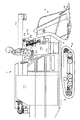
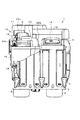
本実施例のコンバイン1の右側面図を図1に、正面図を図2に示す。なお、本明細書では、幅方向又は左側及び右側とはコンバイン1が前進する方向に向いたときの方向を言う。
An embodiment of the present invention will be described with reference to the drawings by using a combine as an example of a work vehicle.
A right side view of the combine 1 of this embodiment is shown in FIG. 1, and a front view is shown in FIG. In the present specification, the width direction or the left side and the right side refer to directions when the combine 1 is directed in the forward direction.
図1および図2に示すように、コンバイン1の車体2の下部側に土壌面を走行する左右一対の走行装置(以下、走行クローラと称す。)3を有する走行装置本体4を配設し、車体2の前端側に分草杆6を備えた刈取装置7が設けられている。刈取装置7の後方には操縦席8を備えた運転台10があり、また車体2の上方には刈取装置7から搬送されてくる穀稈を引き継いで搬送して脱穀、選別する脱穀装置(図示せず)が運転台10の左後方に設けられ、該脱穀装置で脱穀選別された穀粒を一時貯溜するグレンタンク11が脱穀装置の右側に配置されている。グレンタンク11の後部にオーガ12を連接して、グレンタンク11内の穀粒をコンバイン1の外部に排出する構成としている。また、運転台10の左側には防塵カバー13で覆われた作業用ライト9が設けられており、刈取装置7の右前方には前照灯18を備えている。
As shown in FIG. 1 and FIG. 2, a traveling device body 4 having a pair of left and right traveling devices (hereinafter referred to as traveling crawlers) 3 traveling on the soil surface is disposed on the lower side of the vehicle body 2 of the combine 1. On the front end side of the vehicle body 2, a
上記コンバイン1はオペレータが操縦席8に着座してHST主変速レバー14および副変速レバー15(図3参照)を操作し、エンジン(図示せず)の動力を図示しない走行トランスミッションケース内の主変速機を介して変速し、左右の走行クローラ3、3に伝動して任意の速度で走行する。また、オペレータが操向レバー16を左右に傾倒操作することにより各種旋回走行をすることができる。すなわち、操向レバー16をコンバイン1を旋回させようとする方向に傾倒操作することにより、左右の走行クローラ3、3に速度差が与えられて走行方向の変更が行われる構成としている。
In the combine 1, the operator sits on the
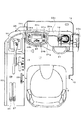
上記コンバイン1の運転台10の平面図を図3に示し、運転台10の左側面図を図4に示す。
図3に示すステップ17と操縦席8を備えた運転台10は、フロント側壁面である前壁部19と左サイド側壁部20を備え、運転台10の右側面はオペレータの乗降用の空間が設けられ、フロント側の前壁部19の右寄り部分にはパワステレバーと略称される操向レバー16と、その後方に近接する位置に操向レバー16を操作する時に操作腕や操作手を置くための受台(ハンドレスト)21と該受台21を支持し、かつオペレータが乗降する時の支えバーとなるアーム22aが車体2上に設けられている。また受台21の左側には走行速度、グレンタンク11内の穀粒の貯留量などを表示するモニタパネル24が設けられ、受台21とモニタパネル24は車体2と一体化した前記アーム22a,22b、22cにより構成されるブリッジと一体的に合成樹脂で成形され、支持されている。
A plan view of the
The
またモニタパネル24の左側であってフロント側の前壁部19の左寄り部分には刈取装置6や走行用の機器を操縦するための操作パネル25が設けられている。これら受台21、アーム22、モニタパネル24及びスイッチ操作用の操作パネル25は一体成形した合成樹脂で成形しても良い。
An
また、左サイド側壁部20には主変速レバー14、副変速レバー15、刈取レバー26、脱穀レバー27及びアクセルレバー28とこれらのレバーを前後左右に操作するためのレバーガイドを備えたガイド板29が設けられている。また、運転台10の後部には操縦席8が設けられている。前記操縦席8はオペレータの乗降用の空間より後部側に位置し、かつ操縦席8の右側部位には取っ手23(図1)が設けられていて、取っ手23は前記受台支えアーム22aと共にオペレータがコンバイン1に乗降する際の把持部となる。
The
前壁部19にはモニタパネル24などが装着されているが、モニタパネル24の下方に開放空間を有し、アーム22と左サイド側壁部20側をブリッジ型に一体成形した構成からなる。そのため、モニタパネル24と、その下方のステップ17との間にできた空間が比較的大きくなる。従って前記空間は操縦席8に着座した標準的な日本人男性の膝が十分入り込む大きさとなる。オペレータは、操縦席8の前方に身を乗り出して穀稈刈取り作業中に分草杆6を監視することをよく行うが、この様な動作をする場合にも前記空間にオペレータの膝が十分入り込むので、前記監視作業を支障なく行うことができる。
A
また、図3に示すように、操向レバー16の左側にモニタパネル24を配置しており、モニタパネル24の中央部に液晶表示画面24aを配し、その下方にエンジン回転計24b、右側に右側のウィンカを点滅させる右ウィンカスイッチ24cとその下方に前照灯スイッチ24e及びホーン24g、左側に左側のウィンカを点滅させる左ウィンカスイッチ24dとその下方に作業用ライトスイッチ24f及び表示切換スイッチ24hがそれぞれ配置されている。なお、通常時はグレンタンク11内の籾の量を表示する液晶表示画面24aが表示切換スイッチ24hを切り換えると、コンバインに設けられる各種センサのチェックができる表示画面となり、更に切り換えると異常の有無を表示する。
Further, as shown in FIG. 3, a
さらに操向レバー16のグリップ高さとモニタパネル24の上面とをほぼ同じ高さとすることで、操向レバー16の操作中に、モニタパネル24の上面に配置した前記スイッチ類の操作がし易くなる。
Further, by setting the grip height of the steering
さらに、図4に示すように左サイド側壁部20に設けた主変速レバー14のグリップとモニタパネル24の上面とをほぼ同じ高さとしている。これらの配置により主変速レバー14を前進方向に倒した時の右横にモニタパネル24があることになり、主変速レバー14の操作中に、モニタパネル24の上面のスイッチ操作がし易くなる。
Further, as shown in FIG. 4, the grip of the
上記配置により、刈取作業時の操向レバー16の位置と前進方向に倒した時の主変速レバー14の間にモニタパネル24がほぼ真横に並ぶことになり、主変速レバー14と操向レバー16が操作し易い位置に操縦席8のシートを合わせてオペレータが座ることで、モニタパネル24の表示画面を楽な姿勢で見ることが出来る。
Due to the above arrangement, the
また、主変速レバー14の前側にスイッチ操作用の操作パネル25があるので、図4に示すように、作業中に主変速レバー14の最高速位置で、該レバー14をオペレータが握った状態で、指を伸ばすと操作パネル25のスイッチを指で操作できる状態となる。
Further, since there is an
このとき、主変速レバー14の最高速位置で、主変速レバー14を握ったオペレータの指が操作パネル25の操作頻度の高いスイッチを操作できるようにする。図5には操作パネル25のスイッチ群とダイヤル群を示すが、上方に注油スイッチ30、方向スイッチ31、扱ぎ深さスイッチ32などの操作頻度の高いスイッチを配置している。
At this time, the operator's finger holding the
注油スイッチ30は油タンク(図示せず)からフィードチェン(図示せず)、刈取装置7の搬送チェンなどに注油をするためのスイッチであり、方向スイッチ31は分草杆6に設けた方向センサ(図示せず)のオン・オフによって機体を真っ直ぐに走行させるための制御スイッチであり、扱ぎ深さスイッチ32は脱穀装置での穀稈の扱ぎ深さを調整するスイッチである。
The
次に、図5に示す操作パネル25に配置されたその他のスイッチ群とダイヤル群について説明する。
知能スイッチ33は主変速レバー14を中立にするとエンジンがアイドリング状態となり、主変速レバー14を中立位置から前、後方向に動かすと、それぞれエンジンが定格回転まで上がる操作をし、さらに籾排出レバーを「入り」にするとエンジン回転を定格にするスイッチである。マイルドスイッチ34は左右のクローラ3,3の前進回転数に差異を設けて行う緩旋回を行うための制御を行うスイッチであり、標準スイッチ35は左右のクローラ3,3の内の一方のみの回転を停止して旋回するための制御を行うスイッチである。
Next, other switch groups and dial groups arranged on the
The
また、知能スイッチ33の調整ダイヤル36は前記知能スイッチ33が「入り」の時に作用し、該スイッチ33の前記した機能に加えて、刈取走行作業中にはエンジン回転を定格値に保持する制御を行うものである。例えば、エンジン回転を最少2600rpmから最大3000rpmの範囲で適宜選択可能であり、前記定格値を2800rpmとする。
The
刈高スイッチ38は左の刈高調整ダイヤル41で設定した高さに刈取装置7を自動保持するための制御を行うスイッチであり、オートリフトスイッチ39は刈取装置7の内部に設けた穀稈センサ(図示せず)が穀稈を検出しなくなり、さらに所定距離走行すると刈取装置7を所定高さまで上昇させるための制御を行うスイッチである。畦際スイッチ40はコンバイン1が畦際に来て刈取装置7を所定高さに上げると主変速レバー14を前進側にしても走行せず、刈取装置7と脱穀装置を作動させるスイッチである。
The cutting
また車体の左右スイッチ43、前後スイッチ44はそれぞれ自動で車体2の左右方向の水平(ローリング制御)と前後方向の水平(ピッチング制御)を保つためのスイッチであり、湿田スイッチ45は湿田での作業時に車両の前進を一旦止めて後進する際において、車体2の前上げ(ピッチングシリンダを利用)を行い、さらに刈取装置7を最上昇させるスイッチである。これらの車体関係スイッチによる車体の傾き度合い又は上昇度合いは左側の傾き調整ダイヤル46で設定できる。即ち、傾き調整ダイヤル46は左右ローリング制御の基準値を、水平に対して左右方向に変更するものである。
Further, the left /
上記操作パネル25のスイッチ群とダイヤル群の中で作業中に設定変更操作しない方が良いもの、例えば刈取装置7の高さ調整用又は車体2の高さ、傾きの調整用のスイッチ群・ダイヤル群38〜46は操作パネル25の下方に設けているので、主変速レバー14を前進位置に操作した場合に、これらのスイッチ群・ダイヤル群38〜46は操作しにくくなり、誤操作を防止することができる。
Of the switch group and dial group of the
また、上記した操作パネル25のダイヤル群36,41,46は左側に配置しているが、これは主変速レバー14を操作しているときにも、これらのダイヤル群36,41,46を操作できるようにするためである。
The dial groups 36, 41, and 46 of the
また、図4に示すように主変速レバー14を倒しても、主変速レバー14が操作パネル25と干渉しないような位置に主変速レバーの回動支点14aを配置することで、主変速レバー14の配置が適正になり、その操作性も楽になる。
Further, as shown in FIG. 4, even if the
さらに、受台21と主変速レバー14の最大前傾時におけるグリップの高さをほぼ同じにしたので、主変速レバー14が最大前傾位置での運転が楽な姿勢ででき、右手の高さと左手の高さが同じ高さになり、オペレータの疲労が軽減される。
Further, since the grip height when the
本発明は操縦性の優れたコンバインとして利用可能性がある。 The present invention can be used as a combine having excellent maneuverability.
1 コンバイン 2 車体
3 走行装置(走行クローラ) 4 走行装置本体
6 分草杆 7 刈取装置
8 操縦席 9 作業用ライト
10 運転台 11 グレンタンク
12 オーガ 13 防塵カバー
14 主変速レバー 14a 主変速レバー回動支点
15 副変速レバー 16 操向レバー
17 ステップ 18 前照灯
19 前壁部 20 側壁部
21 受台 22a,22b、22c アーム
23 取っ手 24 モニタパネル
24a 液晶表示画面 24b エンジン回転計
24c 右ウィンカスイッチ 24d 左ウィンカスイッチ
24e 前照灯スイッチ 24f 作業用ライトスイッチ
24g ホーン 24h 表示切換スイッチ
25 操作パネル 26 刈取レバー
27 脱穀レバー 28 アクセルレバー
29 ガイド板 30 注油スイッチ
31 方向スイッチ 32 扱ぎ深さスイッチ
33 知能スイッチ 34 マイルドスイッチ
35 標準スイッチ 36 知能スイッチの調整ダイヤル
38 刈高スイッチ 39 オートリフトスイッチ
40 畦際スイッチ 41 刈高調整ダイヤル
43 左右スイッチ 44 前後スイッチ
45 湿田スイッチ 46 傾き調整ダイヤル
1 Combine 2 Body
3 traveling device (traveling crawler) 4 traveling device body
6
8 Pilot seat 9 Work light
10
12
14 Main transmission lever 14a Main transmission lever rotation fulcrum
15
17
19
21
23
24a Liquid
24c Right
24e Headlight switch 24f Work light switch
25
27
29
31 direction switch 32 handle depth switch
33
35
38
40
43 Left /
45
Claims (2)
前記運転台(10)の右側面にオペレータの乗降用の空間を設け、前記操向レバー(16)を前壁部(19)の右寄り部分に設け、該操向レバー(16)の後方近傍に操向レバー(16)を操作する時に腕や手を置くための受台(21)を設け、
前記モニタパネル(24)と、受台(21)と、オペレータが乗降するときの支えとなるアーム(22a)と、側壁部(20)側の操作パネル(25)とを合成樹脂でブリッジ型に一体成形して前記モニタパネル(24)の下方とステップ(17)の間に操縦席(8)に着座したオペレータの膝が入り込むだけの大きさの空間を設け、
前記主変速レバー(14)の前側に操作パネル(25)を配置し、
操作パネル(25)には、
主変速レバー(14)を中立位置にするとエンジンがアイドリング状態となり、主変速レバー(14)を中立位置から前後方向に動かすとエンジン回転が定格回転まで上がり、籾排出レバーを入り操作するとエンジン回転を定格回転とする第1スイッチ(33)と、
上記第1スイッチ(33)が入りのときにエンジン回転数を2600rpmから3000rpmの間で選択する調整ダイヤル(36)と、
刈高調整ダイヤル(41)で設定した高さに刈取装置(7)を自動保持するための刈高スイッチ(38)と、
車体(2)の左右方向の傾きを維持制御する左右スイッチ(43)と、この車体(2)の傾き度合いを設定する傾き調整ダイヤル(46)とを設け、
前記調整ダイヤル(36)と刈高調整ダイヤル(41)と傾き調整ダイヤル(46)は、操作パネル(25)の左側の部位に配置し、
前記操向レバー(16)の頂部に設けた第1グリップ部と前傾させた場合の主変速レバー(14)の頂部に設けた第2グリップ部とモニタパネル(24)の上面をほぼ同じ高さに配置し、
主変速レバー(14)を操作しながら前記調整ダイヤル(36)と刈高調整ダイヤル(41)と傾き調整ダイヤル(46)が操作可能であり、
前記主変速レバー(14)を最高速位置に操作した状態では、該主変速レバー(14)を握った指で操作パネル(25)の各スイッチを操作できるように、前記操作パネル(25)と主変速レバー(14)を配置した
ことを特徴とするコンバイン。 A side wall portion (20) which is a side wall surface on the step (17), an operation member installation portion including a main transmission lever (14) for adjusting the vehicle speed disposed on the side wall portion (20), A front wall portion (19) which is a side wall surface, a monitor panel (24) having a screen for displaying information on running and / or work including running speed, fuel amount or contents of work instructions, and a turning direction. A combine provided with a driver's cab (10) having a steering lever (16) for performing operations including, and a cockpit (8) provided in a region surrounded by the front wall (19) and the side wall (20) In
A space for getting on and off the operator is provided on the right side of the cab (10), the steering lever (16) is provided on the right side of the front wall (19), and in the vicinity of the rear of the steering lever (16). A cradle (21) is provided for placing arms and hands when operating the steering lever (16).
The monitor panel (24), the cradle (21), the arm (22 a) that supports the operator when getting on and off, and the operation panel (25) on the side wall (20) side are bridged with synthetic resin. A space is formed so that the knee of the operator seated on the cockpit (8) can enter between the lower part of the monitor panel (24) and the step (17) by being integrally formed ,
An operation panel (25) is disposed in front of the main transmission lever (14),
The operation panel (25) has
When the main speed change lever (14) is set to the neutral position, the engine is idling. When the main speed change lever (14) is moved back and forth from the neutral position, the engine speed increases to the rated speed. A first switch (33) for rated rotation;
An adjustment dial (36) for selecting the engine speed from 2600 rpm to 3000 rpm when the first switch (33) is turned on;
A cutting height switch (38) for automatically holding the cutting device (7) at the height set by the cutting height adjustment dial (41);
A left / right switch (43) for maintaining and controlling the left / right inclination of the vehicle body (2) and an inclination adjustment dial (46) for setting the degree of inclination of the vehicle body (2);
The adjustment dial (36), the cutting height adjustment dial (41), and the inclination adjustment dial (46) are arranged on the left side of the operation panel (25),
The first grip provided on the top of the steering lever (16), the second grip provided on the top of the main transmission lever (14) when tilted forward, and the upper surface of the monitor panel (24) are substantially the same height. Placed in the
The adjustment dial (36), cutting height adjustment dial (41), and tilt adjustment dial (46) can be operated while operating the main speed change lever (14).
In a state where the main transmission lever (14) is operated to the highest speed position, the operation panel (25) and the operation panel (25) are arranged so that each switch of the operation panel (25) can be operated by a finger holding the main transmission lever (14). A combine characterized by disposing a main transmission lever (14) .
Priority Applications (1)
| Application Number | Priority Date | Filing Date | Title |
|---|---|---|---|
| JP2005345775A JP4904790B2 (en) | 2005-11-30 | 2005-11-30 | Combine |
Applications Claiming Priority (1)
| Application Number | Priority Date | Filing Date | Title |
|---|---|---|---|
| JP2005345775A JP4904790B2 (en) | 2005-11-30 | 2005-11-30 | Combine |
Publications (3)
| Publication Number | Publication Date |
|---|---|
| JP2007143532A JP2007143532A (en) | 2007-06-14 |
| JP2007143532A5 JP2007143532A5 (en) | 2008-11-13 |
| JP4904790B2 true JP4904790B2 (en) | 2012-03-28 |
Family
ID=38205695
Family Applications (1)
| Application Number | Title | Priority Date | Filing Date |
|---|---|---|---|
| JP2005345775A Expired - Fee Related JP4904790B2 (en) | 2005-11-30 | 2005-11-30 | Combine |
Country Status (1)
| Country | Link |
|---|---|
| JP (1) | JP4904790B2 (en) |
Families Citing this family (1)
| Publication number | Priority date | Publication date | Assignee | Title |
|---|---|---|---|---|
| JP6639986B2 (en) * | 2016-03-28 | 2020-02-05 | 株式会社クボタ | Combine |
Family Cites Families (7)
| Publication number | Priority date | Publication date | Assignee | Title |
|---|---|---|---|---|
| JPS6445933A (en) * | 1987-08-12 | 1989-02-20 | Nissan Motor | Control device in internal combustion engine with automatic gear |
| JP3507016B2 (en) * | 2000-07-31 | 2004-03-15 | 株式会社クボタ | Working unit structure of work machine |
| JP3641601B2 (en) * | 2001-06-27 | 2005-04-27 | 株式会社クボタ | Harvesting machine front panel structure |
| JP4264700B2 (en) * | 2002-11-13 | 2009-05-20 | 井関農機株式会社 | Self-propelled vehicle |
| JP2004113107A (en) * | 2002-09-26 | 2004-04-15 | Yanmar Agricult Equip Co Ltd | Combine harvester |
| JP2004113191A (en) * | 2002-09-27 | 2004-04-15 | Iseki & Co Ltd | Combine |
| JP4126356B2 (en) * | 2003-11-10 | 2008-07-30 | 井関農機株式会社 | Combine |
-
2005
- 2005-11-30 JP JP2005345775A patent/JP4904790B2/en not_active Expired - Fee Related
Also Published As
| Publication number | Publication date |
|---|---|
| JP2007143532A (en) | 2007-06-14 |
Similar Documents
| Publication | Publication Date | Title |
|---|---|---|
| JP4390072B2 (en) | Combine | |
| JP4371233B2 (en) | Combine | |
| JP4904790B2 (en) | Combine | |
| JP4400678B2 (en) | Combine | |
| JP3919382B2 (en) | Combine drive structure | |
| JP2007143532A5 (en) | ||
| JP3831694B2 (en) | Work vehicle operation switch layout | |
| JP4877053B2 (en) | Combine operating device | |
| JP4935142B2 (en) | Combine | |
| JP2007082564A (en) | Combine harvester | |
| JP4400627B2 (en) | Combine | |
| JP2003143924A (en) | Agricultural working machine | |
| JP2007054006A (en) | Working vehicle | |
| JP2004261147A (en) | Operating device of combine harvester | |
| JP2008271847A5 (en) | ||
| JP5293017B2 (en) | Combine | |
| JP2007228852A5 (en) | ||
| JP3534638B2 (en) | Driving unit structure of combine | |
| JP2007228852A (en) | Combine harvester | |
| JP2006341767A (en) | Working vehicle | |
| JP2600916Y2 (en) | Side panel equipment in combine | |
| JP6614515B2 (en) | Combine | |
| JP5011910B2 (en) | Combine control device | |
| JP7320203B2 (en) | combine | |
| JP2013247915A (en) | Normal combine |
Legal Events
| Date | Code | Title | Description |
|---|---|---|---|
| A521 | Written amendment |
Free format text: JAPANESE INTERMEDIATE CODE: A523 Effective date: 20080930 |
|
| A621 | Written request for application examination |
Free format text: JAPANESE INTERMEDIATE CODE: A621 Effective date: 20081117 |
|
| A977 | Report on retrieval |
Free format text: JAPANESE INTERMEDIATE CODE: A971007 Effective date: 20100910 |
|
| A131 | Notification of reasons for refusal |
Free format text: JAPANESE INTERMEDIATE CODE: A131 Effective date: 20100929 |
|
| A521 | Written amendment |
Free format text: JAPANESE INTERMEDIATE CODE: A523 Effective date: 20101117 |
|
| A131 | Notification of reasons for refusal |
Free format text: JAPANESE INTERMEDIATE CODE: A131 Effective date: 20110511 |
|
| A521 | Written amendment |
Free format text: JAPANESE INTERMEDIATE CODE: A523 Effective date: 20110707 |
|
| TRDD | Decision of grant or rejection written | ||
| A01 | Written decision to grant a patent or to grant a registration (utility model) |
Free format text: JAPANESE INTERMEDIATE CODE: A01 Effective date: 20111213 |
|
| A01 | Written decision to grant a patent or to grant a registration (utility model) |
Free format text: JAPANESE INTERMEDIATE CODE: A01 |
|
| A61 | First payment of annual fees (during grant procedure) |
Free format text: JAPANESE INTERMEDIATE CODE: A61 Effective date: 20111226 |
|
| FPAY | Renewal fee payment (event date is renewal date of database) |
Free format text: PAYMENT UNTIL: 20150120 Year of fee payment: 3 |
|
| R150 | Certificate of patent or registration of utility model |
Ref document number: 4904790 Country of ref document: JP Free format text: JAPANESE INTERMEDIATE CODE: R150 Free format text: JAPANESE INTERMEDIATE CODE: R150 |
|
| LAPS | Cancellation because of no payment of annual fees |