JP4390072B2 - Combine - Google Patents
Combine Download PDFInfo
- Publication number
- JP4390072B2 JP4390072B2 JP2005053363A JP2005053363A JP4390072B2 JP 4390072 B2 JP4390072 B2 JP 4390072B2 JP 2005053363 A JP2005053363 A JP 2005053363A JP 2005053363 A JP2005053363 A JP 2005053363A JP 4390072 B2 JP4390072 B2 JP 4390072B2
- Authority
- JP
- Japan
- Prior art keywords
- vehicle body
- cockpit
- operator
- forward direction
- combine
- Prior art date
- Legal status (The legal status is an assumption and is not a legal conclusion. Google has not performed a legal analysis and makes no representation as to the accuracy of the status listed.)
- Expired - Fee Related
Links
- 235000013339 cereals Nutrition 0.000 claims description 22
- 238000003860 storage Methods 0.000 claims description 7
- 238000009434 installation Methods 0.000 claims description 6
- 238000007599 discharging Methods 0.000 claims description 4
- 238000003306 harvesting Methods 0.000 claims description 2
- NJPPVKZQTLUDBO-UHFFFAOYSA-N novaluron Chemical compound C1=C(Cl)C(OC(F)(F)C(OC(F)(F)F)F)=CC=C1NC(=O)NC(=O)C1=C(F)C=CC=C1F NJPPVKZQTLUDBO-UHFFFAOYSA-N 0.000 claims 2
- 230000005540 biological transmission Effects 0.000 description 15
- 210000003811 finger Anatomy 0.000 description 8
- 210000003127 knee Anatomy 0.000 description 6
- 239000004973 liquid crystal related substance Substances 0.000 description 3
- 239000000463 material Substances 0.000 description 2
- 229920005989 resin Polymers 0.000 description 2
- 239000011347 resin Substances 0.000 description 2
- 229920003002 synthetic resin Polymers 0.000 description 2
- 239000000057 synthetic resin Substances 0.000 description 2
- 210000003813 thumb Anatomy 0.000 description 2
- 241000196324 Embryophyta Species 0.000 description 1
- 229910000831 Steel Inorganic materials 0.000 description 1
- 239000004464 cereal grain Substances 0.000 description 1
- 238000010586 diagram Methods 0.000 description 1
- 238000009313 farming Methods 0.000 description 1
- 210000004247 hand Anatomy 0.000 description 1
- 238000012423 maintenance Methods 0.000 description 1
- 230000007257 malfunction Effects 0.000 description 1
- 230000004048 modification Effects 0.000 description 1
- 238000012986 modification Methods 0.000 description 1
- 239000002689 soil Substances 0.000 description 1
- 239000004071 soot Substances 0.000 description 1
- 239000010959 steel Substances 0.000 description 1
- 239000010902 straw Substances 0.000 description 1
- 230000032258 transport Effects 0.000 description 1
- 238000009333 weeding Methods 0.000 description 1
Images


Classifications
-
- H—ELECTRICITY
- H04—ELECTRIC COMMUNICATION TECHNIQUE
- H04N—PICTORIAL COMMUNICATION, e.g. TELEVISION
- H04N21/00—Selective content distribution, e.g. interactive television or video on demand [VOD]
- H04N21/20—Servers specifically adapted for the distribution of content, e.g. VOD servers; Operations thereof
- H04N21/23—Processing of content or additional data; Elementary server operations; Server middleware
- H04N21/238—Interfacing the downstream path of the transmission network, e.g. adapting the transmission rate of a video stream to network bandwidth; Processing of multiplex streams
- H04N21/2385—Channel allocation; Bandwidth allocation
-
- G—PHYSICS
- G06—COMPUTING; CALCULATING OR COUNTING
- G06F—ELECTRIC DIGITAL DATA PROCESSING
- G06F9/00—Arrangements for program control, e.g. control units
- G06F9/06—Arrangements for program control, e.g. control units using stored programs, i.e. using an internal store of processing equipment to receive or retain programs
- G06F9/46—Multiprogramming arrangements
- G06F9/50—Allocation of resources, e.g. of the central processing unit [CPU]
- G06F9/5005—Allocation of resources, e.g. of the central processing unit [CPU] to service a request
- G06F9/5027—Allocation of resources, e.g. of the central processing unit [CPU] to service a request the resource being a machine, e.g. CPUs, Servers, Terminals
- G06F9/5044—Allocation of resources, e.g. of the central processing unit [CPU] to service a request the resource being a machine, e.g. CPUs, Servers, Terminals considering hardware capabilities
-
- H—ELECTRICITY
- H04—ELECTRIC COMMUNICATION TECHNIQUE
- H04N—PICTORIAL COMMUNICATION, e.g. TELEVISION
- H04N19/00—Methods or arrangements for coding, decoding, compressing or decompressing digital video signals
- H04N19/42—Methods or arrangements for coding, decoding, compressing or decompressing digital video signals characterised by implementation details or hardware specially adapted for video compression or decompression, e.g. dedicated software implementation
-
- H—ELECTRICITY
- H04—ELECTRIC COMMUNICATION TECHNIQUE
- H04N—PICTORIAL COMMUNICATION, e.g. TELEVISION
- H04N21/00—Selective content distribution, e.g. interactive television or video on demand [VOD]
- H04N21/40—Client devices specifically adapted for the reception of or interaction with content, e.g. set-top-box [STB]; Operations thereof
- H04N21/43—Processing of content or additional data, e.g. demultiplexing additional data from a digital video stream; Elementary client operations, e.g. monitoring of home network or synchronising decoder's clock; Client middleware
- H04N21/44—Processing of video elementary streams, e.g. splicing a video clip retrieved from local storage with an incoming video stream, rendering scenes according to MPEG-4 scene graphs
- H04N21/44004—Processing of video elementary streams, e.g. splicing a video clip retrieved from local storage with an incoming video stream, rendering scenes according to MPEG-4 scene graphs involving video buffer management, e.g. video decoder buffer or video display buffer
Landscapes
- Engineering & Computer Science (AREA)
- Signal Processing (AREA)
- Multimedia (AREA)
- Theoretical Computer Science (AREA)
- Software Systems (AREA)
- General Engineering & Computer Science (AREA)
- General Physics & Mathematics (AREA)
- Physics & Mathematics (AREA)
- Computer Networks & Wireless Communication (AREA)
- Harvester Elements (AREA)
- Steering Controls (AREA)
- Instrument Panels (AREA)
- Combines (AREA)
Description
本発明は、植立穀稈を収穫するコンバインに関し、特に運転台の操作性を高めた構成のコンバインに関する。 The present invention relates to a combine that harvests planted cereals, and in particular, to a combine that has a configuration that improves the operability of a driver's cab.
コンバインはクローラを構成する無限履帯の接地面積を広くし、水田など軟弱な圃場でも自由に走行して刈取作業などの農作業を可能としている。
コンバインの操縦席のある運転台には変速レバー、操向レバーなどの各種レバー、各種操作用の操作スイッチ類及び作業内容、車速などを表示する表示装置等が所狭しと配置されている。
これらの操作手段の操作性を改良して機能的に操縦席付近のレイアウトした工夫がなされている(特許文献1)。
A driver's cab with a combine cockpit has various levers such as a shift lever and a steering lever, operation switches for various operations, a display device for displaying work contents, a vehicle speed, and the like.
The operability of these operating means has been improved to devise a functional layout around the cockpit (Patent Document 1).
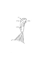
上記従来のコンバインの運転台には各種操作レバー、操作スイッチ、操作ダイヤル及び表示パネルなど、コンバインの操縦、刈り取った穀稈の脱穀処理、脱穀した穀粒の一時的貯蔵と外部への排出のための操作用の機器類が操縦席の廻りに配置されている。前記レバー、スイッチ等の運転台での従来技術のレイアウトでは、図18(a)の平面図、図18(b)の側面図に示すようにオペレータの足下および膝部分のスペースに構造物があり、窮屈で不快感を感じさせる構成となっている。 The above-mentioned conventional combine cab has various operation levers, operation switches, operation dials and display panels, etc. for the operation of the combine, the threshing of the harvested cereal, the temporary storage of the threshed grains and the discharge to the outside The operation equipment is arranged around the cockpit. In the layout of the prior art on the driver's cab such as the lever and switch, there are structures in the operator's feet and knee space as shown in the plan view of FIG. 18A and the side view of FIG. 18B. It is a structure that makes you feel cramped and uncomfortable.
そこで、これらのコンバイン操作用の機器を有機的に配置し、しかもオペレータが乗降するスペースの確保と機器の操作を容易にするレイアウトを工夫する余地はあった。 Therefore, there is room for arranging these combine operation devices in an organic manner, and to devise a layout that makes it easy for the operator to get on and off the space and to operate the devices.
さらに、上記従来のコンバインの運転台のレイアウトではオペレータの足下空間が狭く、操縦席にオペレータが着席した場合に膝が前方の壁面に当たるなどして、作業快適性に改善の余地もあった。 Furthermore, the layout of the above conventional combine cab has a small space for the operator, and there is room for improvement in work comfort, for example, when the operator is seated on the cockpit, the knee hits the front wall.
本発明の課題は、操向操作具の操作性を始め、運転台の不具合を無くし、限られたオペレータ空間を有効に活用し、オペレータの快適性向上を図ったコンバインを提供することである。更に、操向操作具の誤操作を防ぐことのできるコンバインを提供することである。 SUMMARY OF THE INVENTION An object of the present invention is to provide a combine that improves operability of an operator by eliminating the malfunction of a driver's cab, starting from the operability of the steering operation tool, and effectively utilizing the limited operator space. Furthermore, it is providing the combine which can prevent the misoperation of a steering operation tool.
上記課題は次の解決手段で解決される。
請求項1記載の発明は、自走式の車体(2)と、該車体(2)の前端側に備えられ穀稈を刈り取る刈取装置(9)と、該刈取装置(9)により刈り取った穀稈の脱穀後の穀粒を一時貯蔵するグレンタンク(13)と、該グレンタンク(13)内の穀粒を外部に排出するオーガ(15)と、前記車体(2)上に設けた操縦席(20)と車体(2)の前進方向に向かって操縦席(20)の前側に設けたフロント側壁面パネル(32)と車体(2)の前進方向に向かって操縦席(20)の左側に設けたサイド側壁面パネル(33)とを備える運転台(25)を設けたコンバインであって、オペレータが操縦の際に握るグリップ(21a)と車体(2)の前進方向に向かって該グリップ(21a)の左側部に設けたスイッチ(21c)と該スイッチ(21c)の誤操作を防ぐために該スイッチ(21c)とグリップ(21a)との間に設けた指置き用縁(21b)と前記グリップ(21a)を把持する手が滑り落ちないように車体(2)の前進方向に向かって該グリップ(21a)の右側下部に設けた突起部(21d)とを有し車体(2)の旋回を行わせる操向レバー(21)を前記フロント側壁面パネル(32)の右寄り部分に設け、前記サイド側壁面パネル(33)の上部に各種の操作用のスイッチ類と車体(2)の変速操作を行う操作レバー(22,23)を含むレバー類を配置し、前記車体(2)の前進方向に向かって運転台(25)の右側面にはオペレータの乗降用の空間を設け、前記操向レバー(21)の後方近傍に該操向レバー(21)をオペレータが操作する際に腕や手を置くための受台(30)と該受台(30)を支持し且つオペレータが乗降する際の支えとなる受台支えアーム(35)を設け、車体(2)の前進方向に向かって前記受台(30)の左側に前記グレンタンク(13)内の穀粒の貯留量を表示するメータパネル(36)を設け、車体(2)の前進方向に向かって前記メータパネル(36)の左側であってフロント側壁面パネル(32)の左寄り部分には前記刈取装置(9)や走行用の機器を操縦するための操作パネル(37)を設け、前記運転台(25)のオペレータの乗降用の空間よりも後部側に位置し且つ車体(2)の前進方向に向かって操縦席(20)の右側となる位置に受台支えアーム(35)と共にオペレータが乗降する際の把持部となる取っ手(39)を設け、該取っ手(39)と操縦席(20)との間に、前記オーガ(15)を操作可能な着脱自在のリモコンスイッチ(40)の設置部(42)を設け、コンバインの電源の入切用スイッチ(27)とホーン・ウインカ用のコンビスイッチ(28)の操作部を、車体(2)の前進方向に向かって操縦席(20)の右側後方に設けたコンバインである。
The above problem is solved by the following means.
The invention according to claim 1 is a self-propelled vehicle body (2), a reaping device (9) provided on the front end side of the vehicle body (2) for reaping cereal grains, and a grain reaped by the reaping device (9). Glen tank (13) for temporarily storing grain after threshing of straw, auger (15) for discharging grain in grain tank (13) to the outside, and cockpit provided on the vehicle body (2) (20) and the left side of the vehicle body (2) front wall panel provided on the front side of the advancing direction headed cockpit (20) (32) and body (2) cockpit (20) toward the forward direction of the a combine provided cab (25) and a provided side-side wall panels (33), said toward the forward direction of the grip (21a) and the vehicle body (2) the operator grips during maneuvering grip ( 21a) on the left side of the switch (21c) and the switch ( The switch in order to prevent erroneous operation 1c) (21c) and grip (21a) edge for placing a finger that is provided between the (21b) and the grip (21a) body as the hand holding does not slide down (2) A steering lever (21) having a protrusion (21d) provided on the lower right side of the grip (21a) in the forward direction of the vehicle to turn the vehicle body (2), the front side wall surface panel (32). The levers including the operation levers (22, 23) for performing various speed change operations of the vehicle body (2) and the various operation switches are disposed on the right side of the side wall surface panel (33), A space for getting on and off the operator is provided on the right side of the cab (25 ) in the forward direction of the vehicle body (2), and the operator places the steering lever (21) near the rear of the steering lever (21). Arms and hands when operating Kutame cradle (30) and receiving stand the cradle support arm supporting and the operator is supported when passenger (30) (35) is provided, said receiving toward the forward direction of the vehicle body (2) A meter panel (36) is provided on the left side of the platform (30) to display the amount of grain stored in the grain tank (13), and on the left side of the meter panel (36) in the forward direction of the vehicle body (2). An operation panel (37) for maneuvering the reaping device (9) and a traveling device is provided on the left side of the front side wall surface panel (32) for getting on and off the operator of the cab (25). A handle that serves as a grip when the operator gets on and off with the cradle support arm (35) at a position on the rear side of the space and on the right side of the cockpit (20 ) in the forward direction of the vehicle body (2). 39) and the handle (39) An installation part (42) of a detachable remote control switch (40) capable of operating the auger (15) is provided between the vertical seat (20), a combine power on / off switch (27), a horn, the operation portion of the combination switch (28) for blinker, a co Nbain provided on the right rear of the vehicle body cockpit toward the forward direction of (2) (20).
請求項1記載の発明によれば、運転台(25)の各種リモコンスイッチを立体的に構成し、オペレータによる作業中の操作性と視認性を向上させることができる。
また、受台支えアーム(35)や取っ手(39)をオペレータがコンバインに乗降する際に把持して支えにすることができる。
According to invention of Claim 1, various remote control switches of a driver's cab (25) are comprised in three dimensions, and the operativity and visibility during work by an operator can be improved.
Further, the cradle support arm ( 35 ) and the handle (39) can be held and supported when the operator gets on and off the combine.
また、オペレータがオーガ(15)のリモコンスイッチ(40)を使用しないとき、又は操縦席(20)に着席したままリモコンスイッチ(40)を使用するときにはリモコン設置部(42)にリモコンスイッチ(40)を収納しておき、操縦席(20)を離れてオペレータがリモコンスイッチ(40)を使用するときにはこれを携帯することができる。 When the operator does not use the remote control switch (40) of the auger (15) or uses the remote control switch (40) while sitting on the cockpit (20), the remote control switch (40) is connected to the remote control installation part (42). Can be carried when the operator uses the remote control switch (40) after leaving the cockpit (20) .
更に、操向レバー(21)のグリップ(21a)とスイッチ(21c)との間に指置き用縁(21b)を設けることで、この指置き用縁(21b)に指をのせておいても指がうっかり滑り落ちることがない。そのため操向レバー(21)のスイッチ(21c)の誤操作を防ぐことができる。Further, by providing a finger placement edge (21b) between the grip (21a) of the steering lever (21) and the switch (21c), even if the finger is placed on the finger placement edge (21b). Fingers do not inadvertently slide down. Therefore, an erroneous operation of the switch (21c) of the steering lever (21) can be prevented.
また、操向レバー(21)のグリップ(21a)下部に突起部(21d)を設けることで、グリップ(21a)を把持する手が前記突起部(21d)から滑り落ちない。Further, by providing the protrusion (21d) at the lower part of the grip (21a) of the steering lever (21), the hand holding the grip (21a) does not slide off from the protrusion (21d).
本発明の実施の形態を図面と共に説明する。
図1は本実施例のコンバイン1の左側面図であり、図2は本実施例のコンバイン1の右側面図である。なお、本明細書では、左側及び右側とはコンバイン1が前進する方向に向いたときの方向を言う。
Embodiments of the present invention will be described with reference to the drawings.
FIG. 1 is a left side view of the combine 1 of the present embodiment, and FIG. 2 is a right side view of the combine 1 of the present embodiment. In the present specification, the left side and the right side refer to directions when the combine 1 is directed in the forward direction.
図1および図2に示すように、コンバイン1の車体2の下部側に土壌面を走行する左右一対の走行装置(以下、走行クローラと称す。)3を有する走行装置本体4を配設し、車体2の前端側に分草杆8を備えた刈取装置9が設けられている。刈取装置9は車体2の上方の支点を中心にして上下動する刈取装置支持フレーム7で支持されているので、コンバイン1に搭乗したオペレータが運転台の操縦席20の操向レバー21を前後に傾倒操作することにより、刈取装置支持フレーム7と共に上下に昇降する構成である。
As shown in FIG. 1 and FIG. 2, a traveling
車体2の上方には、刈取装置9から搬送されてくる穀稈を引き継いで搬送して脱穀、選別する脱穀装置10と該脱穀装置10で脱穀選別された穀粒を一時貯溜するグレンタンク13が載置され、グレンタンク13の後部にオーガ15を連接して、グレンタンク13内の穀粒をコンバイン1の外部に排出する構成としている。
Above the
すなわち、コンバイン1はオペレータが操縦席20においてHST主変速レバー22および副変速レバー23を操作し、エンジン(図示せず)の動力を図示しない走行トランスミッションケース内の主変速機を介して変速し、左右の走行クローラ3、3に伝動して任意の速度で走行する。
That is, the combine 1 shifts the power of the engine (not shown) through a main transmission in a traveling transmission case (not shown) by the operator operating the HST
また、コンバイン1は、オペレータが操縦席20において操向レバー21を左右に傾倒操作することにより各種旋回走行することができる。すなわち、操向レバー21をコンバイン1を旋回させようとする方向に傾倒操作することにより、左右の走行クローラ3、3に速度差が与えられて走行方向の変更が行われる構成としている。また、操向レバー21を前後方向に移動させることにより刈取装置9を昇降させる構成としている。
Further, the combine 1 can travel in various turns by the operator tilting the steering
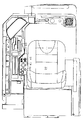
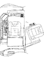
図3〜図17には操向レバー21とハンドレスト30などを含む運転台25の構成を示す。
図3は、操縦席20を含む運転台25の斜め後上方から見た斜視図であり、図4は運転台25のフロント壁面の斜め後上方から見た斜視図である。運転台25はフロント側の壁面パネル32と左サイド壁面パネル33を備え、運転台25の右側面はオペレータの乗降用の空間が設けられている。前記フロント側の壁面パネル32の右寄り部分にはパワステレバーと略称される操向レバー21、その後方に近接する位置に、操向レバー21を操作する時に操作腕や操作手を置くための受台(ハンドレスト)30と該受台30を支持し、かつオペレータが乗降する時の支えバーとなるアーム35が機体に設けられている。また受台30の左側には走行速度、グレンタンク内の穀粒の貯留量などを表示するフロントメータパネル36が設けられ、またメータパネル36の左側であってフロント側の壁面パネル32の左寄り部分には刈取装置9や走行用の機器を操縦するための操作パネル37が設けられている。これら受台30、アーム35、メータパネル36及び操作パネル37は一体成形した合成樹脂から得られる。
3 to 17 show a configuration of the
FIG. 3 is a perspective view of the driver's
また、左サイド側壁面パネル33には主変速レバー22と副変速レバー23、刈取・脱穀レバー24及びアクセルレバー26とこれらのレバーを前後左右に操作するためのレバーガイドを備えたガイド板38が設けられている。また、運転台25の後部には操縦席20が設けられているが、オペレータの乗降用の空間より後部側に位置し、かつ操縦席20の右側部位には取っ手39が機体に設けられていて、取っ手39は前記受台支えアーム35と共にオペレータがコンバイン1に乗降する際の把持部となる。
The left side
さらに、前記操縦席20と取っ手39の間にはオーガコントロール用のオーガ操作パネル(リモコンスイッチ)40の設置部42(図8参照)が設けられている。従ってオペレータがオーガ操作パネル(リモコンスイッチ)40を使用しないとき、又は操縦席20に着席したまま、オーガ操作パネル40を使用するときにはリモコン設置部42にリモコンスイッチ40を収納しておき、操縦席20を離れてオペレータがリモコンスイッチ40を使用するときにはこれを携帯することができる。オーガ15から籾を排出する作業をする場合に、例えば左右方向へのオーガ15の移動時などにおいてオーガ操作パネル40に配置されるオーガ15の左側又は右側への各移動用のスイッチの位置がオーガの移動方向と逆になるとオペレータは操作が難しくなるが、上記したようにオーガ操作パネル40の左側又は右側への各オーガ移動用のスイッチの配置位置とオーガ15の移動方向が一致する方向にオーガ操作パネル40を向けることで、オペレータはオーガの左右移動操作を容易に行うことができる。
Further, an installation portion 42 (see FIG. 8) of an auger operation panel (remote control switch) 40 for auger control is provided between the
また、オペレータが操縦席20に着席した時に膝がフロント側の壁面パネル32と左サイド側壁面パネル33の内壁面にあたらないように各種スイッチ、レバー群の配置部分の下方部分に大きな窪み部32a,32bを形成する。特に、従来フロント側の壁面パネル32に設けられていた各種スイッチを左サイド側壁面パネル33に移し、また、操向レバー21がオペレータの右膝に当たらないように従来よりフロント側の壁面パネル32の上方に配置したので、オペレータが操縦席20に着席した時に左右の膝が当たらないようにフロント側の壁面パネル32の下方部分に大きな窪み32a,32bを形成することができ、オペレータが窮屈な思いをすることなくコンバイン1の操縦ができる。図5(図5(a)は平面図、図5(b)は側面図、図5(c)は斜視図)に上記構成の概略図を示す。
Further, when the operator is seated in the
また、コンバイン1の電源を入れるメインキー27とホーン・ウインカ用のコンビスイッチ28等の操作部をフロント側の壁面パネル上面の操作部には設けず、操縦席右後方の機体側に設けたので、その分オペレータが操縦席20に着席したときに膝が当たらない空間が大きくなる。
In addition, the operation part such as the main key 27 for turning on the power of the combine 1 and the
このように、運転台25の各種操作部を立体的に構成し、デッドスペースを有効活用することにより、オペレータの足下空間を拡大し、快適性の向上を図り、メータや自動スイッチ類をオペレータ前面にレイアウトし、オペレータによる作業中の操作性と視認性を向上させることができる。
In this way, the various operation sections of the
上記受台30、アーム35、メータパネル36及び操作パネル37は一体成形した合成樹脂を上型と下型に分割して製造され、得られた上型と下型の間に強度部材として断面U字の鋼材フレーム(図示せず)を入れた後に前記上型と下型を重ね合わせて一体化した構成である。こうして上型と下型を重ね合わせて一体化した樹脂内にハーネスを配策する際にスペースを確保することができる。
また、操縦席20の前方のハンドルを樹脂で「上型」、「下型」に分割できるよう設け、ハンドルの中に硬度部材としてU字のフレームを通してもよい。
The
Further, the handle in front of the
図6の操向レバー21の左後方から見た図に示すように操向レバー21のグリップ21aの左側に指置き用縁21b(図6(a))を設けておくと、この指置き用縁21bに親指をのせておいても(図6(b))、親指がうっかり滑り落ちることがない。そのため操向レバー21のグリップ21aの左側に設けたスイッチ21cの誤操作を防ぐことができる。
As shown in the view from the left rear of the steering
また、図7の操向レバー21の右前方から見た図に示すように操向レバー21のグリップ21aの右側下部に突起部21dを設けているので、グリップ21aを把持する手が前記突起部21dから滑り落ちない。
Further, as shown in the drawing viewed from the right front of the steering
また、オーガ操作用のオーガ操作パネル40は操縦席20の右側に載置できるように機体に窪みを設けているが、操縦席20の左右側部のどちら側にでも載置できるように操縦席20の左側にも窪みを設けておくことが望ましい。
このとき図8、図9の操縦席20付近の平面図にそれぞれ示すようにオーガ操作パネル40は操縦席20の左側部と右側部に配置する場合とではオーガ操作パネル40の前後方向を互いに反対向きにして配置することができる。
図8に示すように操縦席20の右側部に配置する場合は、オペレータは座ったまま、右後ろを振り返りながらオーガ操作パネル40を操作するが、図9に示すように操縦席20の左側部に配置する場合は、オペレータの真後ろにオーガ15を張り出す際に、起立して後ろ向きになってオーガ操作パネル40の操作をするのに都合の良いように各オーガ移動用のスイッチを配置する。こうしてオペレータの操作する向きを基準としてオーガ15の旋回方向を統一することで誤操作を防止することができる。
Further, the
At this time, as shown in the plan views of the vicinity of the
As shown in FIG. 8, when the operator is placed on the right side of the
また、操縦席20の下方にあるエンジンをメンテナンスするために図10、図11に示すようにエンジンカバー(図示せず)を側方にオープンする場合に操縦席20と共にオーガ操作パネル40も一体で開くように構成する。
Further, when the engine cover (not shown) is opened to the side as shown in FIGS. 10 and 11 to maintain the engine below the
上記構成によりエンジンなどのメンテナンスが容易となる。特に操縦席20の左側にオーガ操作パネル40を配置した場合に、エンジンカバーと一体でオーガ操作パネル40をオープンしないと、配線が邪魔になったり、配線を切断してしまったりすることがあるが、上記構成で、そのような不具合を防ぐことができる。
The above configuration facilitates maintenance of the engine and the like. In particular, when the
また、図8及び図12に示すように操縦席20の側部にオーガ操作パネル40を配置する場合に、コンバインの走行中は、オーガ手動レバー43を無効にし、オーガ15の自動張出・自動収納スイッチ44のみを有効にする。これは、コンバイン1の操縦席20の近傍にオーガ操作パネル40を設けているので、オペレータが不用意にオーガ手動レバー43に接触して、オーガ15を誤操作させることを防ぐためである。自動張出・自動収納スイッチ44はオーガ手動レバー43に比べて小さく、不意に触ったりするおそれがないので自動張出・自動収納スイッチ44のみはコンバインの走行中でも有効にしておく。また、オーガ操作パネル40にはこの他にオーガ自動張出位置設定ダイヤル45、緊急停止スイッチ46、籾排出スイッチ47等が設けられている。
8 and 12, when the
また、本発明の他の実施例として図13に示すように操縦席20の左側に設けた各種レバーのガイド板38等を備えた操作部の更に外側の側方にサイド操作表示部50を設け、該表示部50には液晶表示体を用いる。この表示部50にはフロントメータパネル36の情報(メイン情報)以外の情報、例えばグレンタンク内の籾の量、車体の傾き加減、旋回走行時の旋回パターン(緩旋回、ブレーキ旋回、スピン旋回)など常時表示させておく。
As another embodiment of the present invention, as shown in FIG. 13, a side
従来は、液晶を用いるメータ類の情報表示部の面積が少なく、必要な情報は液晶表示部の表示切り替えで対応していたが、素早く必要な情報を確認することができなかった。しかし、本実施例では作業情報の表示量が増えても、オペレータは常時複数の情報を確認することができる。 Conventionally, the area of the information display section of meters using liquid crystal is small, and necessary information has been dealt with by switching the display of the liquid crystal display section. However, necessary information could not be confirmed quickly. However, in this embodiment, even if the display amount of work information increases, the operator can always confirm a plurality of pieces of information.
また、図14に示すように操縦席20の背もたれの右側中央部にオーガ操作パネル40を取り付ける。またオーガ操作パネル40は肘掛けのように操縦席20の背もたれの右側で上下方向に回動可能にして、使用しないときは図14の一点鎖線に示すように背もたれ側部に収納可能にして誤操作を防止できるようにしても良い。
Further, as shown in FIG. 14, the
さらに、本発明の他の実施例として図15に示すようにフロントメータパネル36を受け台支えアーム35の基部の回動支点35aに回動自在に取り付け、この受け台取付アーム35の回動支点35aを支点にして回動可能にしてメータパネル36のメータの表示状態が、例えば立ち位置に居る作業者など、操縦席20に着席しているオペレータとは条件が違う人間ごとに、それぞれ見えやすい位置にメータパネル36の表示面を向けることができるように回転角度を調整可能にしている。
Further, as another embodiment of the present invention, as shown in FIG. 15, the
さらに本発明の他の実施例として図16に示すように操縦席20に着席するオペレータの足下位置にある補助ステップ52の上部にシート53を取り付けても良い。なお、本実施例は図3に示す実施例の変形例であるが本実施例でも主変速レバー22、副変速レバー23、刈取・脱穀レバー24等を操縦席20の左側のガイド板38設置部に設けている。
Furthermore, as another embodiment of the present invention, as shown in FIG. 16, a seat 53 may be attached to the upper part of the
前記シート53は補助ステップ52の上部だけでなく、その後半分は操縦席20の着席部の下方まで一体化した折れ曲り形状の板材からなる。そして該シート53は操縦席20の着席部の下方のほぼ中央部に鉛直方向に向いた軸心Cを中心に回動可能に構成している。
The seat 53 is not only the upper part of the
従来は補助ステップ52は操縦席20とともにコンバイン1の車体2に固定されていたので、オーガ15から籾を外部に排出するとき等の作業時において、オペレータは操縦席20に座ったままコンバイン1の外側を向いての作業が困難であった。しかし、前記補助ステップ52上のシート53を外側に回動させることで、オペレータはシート53上に乗ったまま、コンバイン1の機体の外側からオーガ15より排出する籾の様子を確認しながらの作業を容易に行える。
Conventionally, since the
ところで、最近のコンバイン1はスイッチ操作の使用頻度が増えているが、従来の運転台25のレイアウトでは各種レバー類とスイッチ群が多数あり、しかも使用頻度の高い各種レバーを操作しやすい位置に配置しているので、スイッチ類はオペレータから外れた位置にある場合が多い。
By the way, although the frequency of use of switch operation is increasing recently, there are a lot of various levers and switch groups in the layout of the
そこで本発明の実施例として図17(a)の斜視図と図17(b)の主変速レバー22のアーム22aの取付部の側面図に示すように、コンバイン1用の操縦席20の左側の壁面パネル55の側面の鉛直方向の壁面にL字状のアーム22aを備えたHSTなどの主変速レバー22を取り付けた構成を用いることができる。
Therefore, as an embodiment of the present invention, as shown in the perspective view of FIG. 17A and the side view of the mounting portion of the
主変速レバー22を前記壁面パネル55の壁面部より取り出すことで、主変速レバー22とスイッチ類の両方をオペレータの近い位置にレイアウトすることができ、安定した操作空間が提供できる。
By taking out the
本発明は操縦性の優れたコンバインとして利用可能性がある。 The present invention can be used as a combine having excellent maneuverability.
1 コンバイン 2 車体
3 走行装置(走行クローラ) 4 走行装置本体
7 刈取装置支持フレーム 8 分草杆
9 刈取装置 10 脱穀装置
13 グレンタンク 15 オーガ
20 操縦席 21 操向レバー
21a グリップ 21b 指置き用縁
21c スイッチ 21d 突起部
22 主変速レバー 22a L字状のアーム
23 副変速レバー 24 刈取・脱穀レバー
25 運転台 26 アクセルレバー
27 メインキー 28 ホーン・ウインカ用コンビスイッチ
30 ハンドレスト 32 フロント側壁面パネル
33 サイド側壁面パネル 35 受台支えアーム
36 フロントメータパネル 37 操作パネル
38 ガイド板 39 取っ手
40 オーガ操作パネル 42 オーガ操作パネル設置部
43 オーガ手動レバー 44 オーガ自動張出・収納スイッチ
45 オーガ自動張出位置設定ダイヤル
46 オーガ緊急停止スイッチ 47 籾排出スイッチ
50 サイド操作表示部 52 補助ステップ
53 シート 55 左側壁面パネル
DESCRIPTION OF SYMBOLS 1
Claims (1)
オペレータが操縦の際に握るグリップ(21a)と車体(2)の前進方向に向かって該グリップ(21a)の左側部に設けたスイッチ(21c)と該スイッチ(21c)の誤操作を防ぐために該スイッチ(21c)とグリップ(21a)との間に設けた指置き用縁(21b)と前記グリップ(21a)を把持する手が滑り落ちないように車体(2)の前進方向に向かって該グリップ(21a)の右側下部に設けた突起部(21d)とを有し車体(2)の旋回を行わせる操向レバー(21)を前記フロント側壁面パネル(32)の右寄り部分に設け、
前記サイド側壁面パネル(33)の上部に各種の操作用のスイッチ類と車体(2)の変速操作を行う操作レバー(22,23)を含むレバー類を配置し、
前記車体(2)の前進方向に向かって運転台(25)の右側面にはオペレータの乗降用の空間を設け、
前記操向レバー(21)の後方近傍に該操向レバー(21)をオペレータが操作する際に腕や手を置くための受台(30)と該受台(30)を支持し且つオペレータが乗降する際の支えとなる受台支えアーム(35)を設け、
車体(2)の前進方向に向かって前記受台(30)の左側に前記グレンタンク(13)内の穀粒の貯留量を表示するメータパネル(36)を設け、
車体(2)の前進方向に向かって前記メータパネル(36)の左側であってフロント側壁面パネル(32)の左寄り部分には前記刈取装置(9)や走行用の機器を操縦するための操作パネル(37)を設け、
前記運転台(25)のオペレータの乗降用の空間よりも後部側に位置し且つ車体(2)の前進方向に向かって操縦席(20)の右側となる位置に受台支えアーム(35)と共にオペレータが乗降する際の把持部となる取っ手(39)を設け、
該取っ手(39)と操縦席(20)との間に、前記オーガ(15)を操作可能な着脱自在のリモコンスイッチ(40)の設置部(42)を設け、
コンバインの電源の入切用スイッチ(27)とホーン・ウインカ用のコンビスイッチ(28)の操作部を、車体(2)の前進方向に向かって操縦席(20)の右側後方に設けたことを特徴とするコンバイン。 A self-propelled vehicle body (2), a reaping device (9) provided on the front end side of the vehicle body (2) for harvesting cereals, and grains after threshing of cereals harvested by the reaping device (9) A Glen tank (13) for temporary storage, an auger (15) for discharging grains in the Glen tank (13) to the outside, a cockpit (20) and a vehicle body (2) provided on the vehicle body (2) side side wall panels provided on the left side of the front side wall panel provided on the front side of the cockpit toward the forward direction (20) (32) and body (2) cockpit toward the forward direction of (20) (33 ) With a cab (25) comprising:
A grip (21a) held by an operator during steering and a switch (21c) provided on the left side of the grip (21a) in the forward direction of the vehicle body (2) and the switch (21c) to prevent erroneous operation of the switch (21c) (21c) and the grip (21a) between the finger placement edge (21b) and the grip (21a) toward the forward direction of the vehicle body (2) so that the hand holding the grip (21a) does not slide down. A steering lever (21) having a protrusion (21d) provided on the lower right side of 21a) for turning the vehicle body (2) is provided on the right side of the front side wall panel (32);
Arranged on the upper part of the side wall surface panel (33) are levers including various operation switches and operation levers (22, 23) for performing a shifting operation of the vehicle body (2),
A space for getting on and off the operator is provided on the right side surface of the cab (25) toward the forward direction of the vehicle body (2) ,
A pedestal (30) for placing an arm or hand when the operator operates the steering lever (21) in the vicinity of the rear of the steering lever (21), supports the cradle (30), and the operator A cradle support arm (35) is provided to support when getting on and off,
A meter panel (36) is provided on the left side of the cradle (30) toward the forward direction of the vehicle body (2) to display the amount of stored grains in the grain tank (13).
An operation for maneuvering the cutting device (9) and the traveling device on the left side of the meter panel (36) toward the forward direction of the vehicle body (2) and on the left side of the front side wall panel (32). A panel (37) is provided;
Along with the cradle support arm (35) at a position on the right side of the cockpit (20) toward the forward direction of the vehicle body (2) and located on the rear side of the space for getting on and off the operator of the cab (25) A handle (39) is provided as a grip when the operator gets on and off,
Between the handle (39) and the cockpit (20), an installation part (42) of a detachable remote control switch (40) capable of operating the auger (15) is provided,
The operation part of the combine power switch (27) and the combination switch for the horn and turn signal (28) are provided on the rear right side of the cockpit (20) in the forward direction of the vehicle body (2). A featured combine.
Priority Applications (3)
| Application Number | Priority Date | Filing Date | Title |
|---|---|---|---|
| JP2005053363A JP4390072B2 (en) | 2005-02-28 | 2005-02-28 | Combine |
| KR1020060013427A KR100732507B1 (en) | 2005-02-28 | 2006-02-13 | Harvester |
| CNB2006100577921A CN100426946C (en) | 2005-02-28 | 2006-02-27 | Combined harvester |
Applications Claiming Priority (1)
| Application Number | Priority Date | Filing Date | Title |
|---|---|---|---|
| JP2005053363A JP4390072B2 (en) | 2005-02-28 | 2005-02-28 | Combine |
Related Child Applications (1)
| Application Number | Title | Priority Date | Filing Date |
|---|---|---|---|
| JP2007021331A Division JP4400627B2 (en) | 2007-01-31 | 2007-01-31 | Combine |
Publications (3)
| Publication Number | Publication Date |
|---|---|
| JP2006230353A JP2006230353A (en) | 2006-09-07 |
| JP2006230353A5 JP2006230353A5 (en) | 2007-03-29 |
| JP4390072B2 true JP4390072B2 (en) | 2009-12-24 |
Family
ID=36945551
Family Applications (1)
| Application Number | Title | Priority Date | Filing Date |
|---|---|---|---|
| JP2005053363A Expired - Fee Related JP4390072B2 (en) | 2005-02-28 | 2005-02-28 | Combine |
Country Status (3)
| Country | Link |
|---|---|
| JP (1) | JP4390072B2 (en) |
| KR (1) | KR100732507B1 (en) |
| CN (1) | CN100426946C (en) |
Families Citing this family (13)
| Publication number | Priority date | Publication date | Assignee | Title |
|---|---|---|---|---|
| JP4998053B2 (en) * | 2007-03-30 | 2012-08-15 | 井関農機株式会社 | Combine |
| JP5016391B2 (en) * | 2007-06-01 | 2012-09-05 | 株式会社クボタ | Harvester operating section structure |
| JP2009081933A (en) * | 2007-09-26 | 2009-04-16 | Railway Technical Res Inst | Doze detection steering wheel and vehicular control method using the same |
| KR101131818B1 (en) * | 2010-03-12 | 2012-03-30 | 이세키노우키가부시키가이샤 | Combine |
| CN102550207B (en) * | 2010-12-31 | 2016-01-20 | 官福堂 | Whole-feed rice combine harvester |
| JP5682816B2 (en) * | 2011-02-16 | 2015-03-11 | 株式会社アテックス | Riding mower |
| KR102422584B1 (en) * | 2014-09-02 | 2022-07-20 | 가부시끼 가이샤 구보다 | Harvester |
| JP6811687B2 (en) * | 2017-06-29 | 2021-01-13 | 株式会社クボタ | combine |
| CN112004406B (en) * | 2018-05-31 | 2023-04-11 | 株式会社久保田 | Combine harvester |
| KR20200078327A (en) * | 2018-12-21 | 2020-07-01 | 가부시끼 가이샤 구보다 | Combine |
| JP2022140116A (en) * | 2021-03-12 | 2022-09-26 | ヤンマーホールディングス株式会社 | Operation device for working machine, and working machine |
| JP7223346B2 (en) * | 2021-06-28 | 2023-02-16 | 井関農機株式会社 | combine |
| JP7223348B1 (en) | 2021-09-29 | 2023-02-16 | 井関農機株式会社 | combine |
Family Cites Families (8)
| Publication number | Priority date | Publication date | Assignee | Title |
|---|---|---|---|---|
| JPH10262440A (en) * | 1997-03-21 | 1998-10-06 | Mitsubishi Agricult Mach Co Ltd | Maneuvering part structure for combine |
| JP3435020B2 (en) * | 1997-06-13 | 2003-08-11 | 株式会社クボタ | Control structure of combine |
| JPH1118557A (en) * | 1997-07-07 | 1999-01-26 | Iseki & Co Ltd | Manipulator for farm equipment |
| JP3919382B2 (en) * | 1999-05-19 | 2007-05-23 | 株式会社クボタ | Combine drive structure |
| JP2002160659A (en) * | 2000-11-28 | 2002-06-04 | Honda Motor Co Ltd | Drive control device for vehicle and control program of the controller |
| JP2003237615A (en) * | 2002-02-18 | 2003-08-27 | Iseki & Co Ltd | Travelling device for working machine |
| JP3831694B2 (en) * | 2002-09-04 | 2006-10-11 | ヤンマー農機株式会社 | Work vehicle operation switch layout |
| JP4042503B2 (en) * | 2002-09-06 | 2008-02-06 | 井関農機株式会社 | Combine |
-
2005
- 2005-02-28 JP JP2005053363A patent/JP4390072B2/en not_active Expired - Fee Related
-
2006
- 2006-02-13 KR KR1020060013427A patent/KR100732507B1/en not_active IP Right Cessation
- 2006-02-27 CN CNB2006100577921A patent/CN100426946C/en not_active Expired - Fee Related
Also Published As
| Publication number | Publication date |
|---|---|
| CN1826852A (en) | 2006-09-06 |
| KR100732507B1 (en) | 2007-06-27 |
| JP2006230353A (en) | 2006-09-07 |
| CN100426946C (en) | 2008-10-22 |
| KR20060095461A (en) | 2006-08-31 |
Similar Documents
| Publication | Publication Date | Title |
|---|---|---|
| JP4390072B2 (en) | Combine | |
| US6634453B2 (en) | Ergonomic tractor seat armrest and hand control | |
| JP5835154B2 (en) | Work vehicle | |
| JP4400678B2 (en) | Combine | |
| JP4371233B2 (en) | Combine | |
| JP2000279021A (en) | Structure of operating part of harvester | |
| US6612636B2 (en) | Hand reference for control panel of utility vehicle | |
| JP4400627B2 (en) | Combine | |
| GB2491855A (en) | Control lever with interchangeable hand grip | |
| JP4265687B2 (en) | Combine | |
| JP3831694B2 (en) | Work vehicle operation switch layout | |
| JP2007054006A (en) | Working vehicle | |
| JP6935367B2 (en) | Work vehicle | |
| JP2007082564A (en) | Combine harvester | |
| JP2004313035A (en) | Apparatus for operating working vehicle of combine harvester or the like | |
| JP2007008222A (en) | Arm rest structure of working vehicle | |
| WO2022190833A1 (en) | Operation device for work machine, and work machine | |
| JPH086673Y2 (en) | Control device for riding agricultural machine | |
| JP6973892B2 (en) | Work vehicle | |
| JP4904790B2 (en) | Combine | |
| JP7041893B2 (en) | Work vehicle | |
| JP2010215058A (en) | Driver's cabin structure of service vehicle | |
| JP6961540B2 (en) | Work vehicle | |
| WO2008050493A1 (en) | Steering handle and work vehicle having it | |
| JP3097082B2 (en) | Working machine operating device |
Legal Events
| Date | Code | Title | Description |
|---|---|---|---|
| A621 | Written request for application examination |
Free format text: JAPANESE INTERMEDIATE CODE: A621 Effective date: 20070109 |
|
| A521 | Request for written amendment filed |
Free format text: JAPANESE INTERMEDIATE CODE: A523 Effective date: 20070214 |
|
| A977 | Report on retrieval |
Free format text: JAPANESE INTERMEDIATE CODE: A971007 Effective date: 20080605 |
|
| A131 | Notification of reasons for refusal |
Free format text: JAPANESE INTERMEDIATE CODE: A131 Effective date: 20080618 |
|
| A521 | Request for written amendment filed |
Free format text: JAPANESE INTERMEDIATE CODE: A523 Effective date: 20080814 |
|
| A131 | Notification of reasons for refusal |
Free format text: JAPANESE INTERMEDIATE CODE: A131 Effective date: 20090107 |
|
| A521 | Request for written amendment filed |
Free format text: JAPANESE INTERMEDIATE CODE: A523 Effective date: 20090305 |
|
| TRDD | Decision of grant or rejection written | ||
| A01 | Written decision to grant a patent or to grant a registration (utility model) |
Free format text: JAPANESE INTERMEDIATE CODE: A01 Effective date: 20090916 |
|
| A01 | Written decision to grant a patent or to grant a registration (utility model) |
Free format text: JAPANESE INTERMEDIATE CODE: A01 |
|
| FPAY | Renewal fee payment (event date is renewal date of database) |
Free format text: PAYMENT UNTIL: 20121016 Year of fee payment: 3 |
|
| R150 | Certificate of patent or registration of utility model |
Free format text: JAPANESE INTERMEDIATE CODE: R150 |
|
| A61 | First payment of annual fees (during grant procedure) |
Free format text: JAPANESE INTERMEDIATE CODE: A61 Effective date: 20090929 |
|
| FPAY | Renewal fee payment (event date is renewal date of database) |
Free format text: PAYMENT UNTIL: 20121016 Year of fee payment: 3 |
|
| FPAY | Renewal fee payment (event date is renewal date of database) |
Free format text: PAYMENT UNTIL: 20151016 Year of fee payment: 6 |
|
| LAPS | Cancellation because of no payment of annual fees |