JP4887652B2 - Jet generator and electronic device - Google Patents
Jet generator and electronic device Download PDFInfo
- Publication number
- JP4887652B2 JP4887652B2 JP2005123656A JP2005123656A JP4887652B2 JP 4887652 B2 JP4887652 B2 JP 4887652B2 JP 2005123656 A JP2005123656 A JP 2005123656A JP 2005123656 A JP2005123656 A JP 2005123656A JP 4887652 B2 JP4887652 B2 JP 4887652B2
- Authority
- JP
- Japan
- Prior art keywords
- frequency
- signal
- drive mechanism
- diaphragm
- gas
- Prior art date
- Legal status (The legal status is an assumption and is not a legal conclusion. Google has not performed a legal analysis and makes no representation as to the accuracy of the status listed.)
- Expired - Fee Related
Links
- 230000007246 mechanism Effects 0.000 claims description 48
- 230000017525 heat dissipation Effects 0.000 claims description 24
- 238000010438 heat treatment Methods 0.000 claims description 13
- 230000004044 response Effects 0.000 claims description 4
- 230000007423 decrease Effects 0.000 description 15
- 239000007789 gas Substances 0.000 description 12
- 238000000034 method Methods 0.000 description 6
- 238000010586 diagram Methods 0.000 description 5
- 239000011347 resin Substances 0.000 description 5
- 229920005989 resin Polymers 0.000 description 5
- 239000005060 rubber Substances 0.000 description 5
- 238000007599 discharging Methods 0.000 description 4
- 230000020169 heat generation Effects 0.000 description 4
- 230000009471 action Effects 0.000 description 3
- 238000007664 blowing Methods 0.000 description 3
- 239000003990 capacitor Substances 0.000 description 3
- 238000001816 cooling Methods 0.000 description 3
- 230000003247 decreasing effect Effects 0.000 description 3
- 229910052751 metal Inorganic materials 0.000 description 3
- 239000002184 metal Substances 0.000 description 3
- 230000002829 reductive effect Effects 0.000 description 3
- 238000005070 sampling Methods 0.000 description 3
- 230000001360 synchronised effect Effects 0.000 description 3
- XKRFYHLGVUSROY-UHFFFAOYSA-N Argon Chemical compound [Ar] XKRFYHLGVUSROY-UHFFFAOYSA-N 0.000 description 2
- IJGRMHOSHXDMSA-UHFFFAOYSA-N Atomic nitrogen Chemical compound N#N IJGRMHOSHXDMSA-UHFFFAOYSA-N 0.000 description 2
- 230000002238 attenuated effect Effects 0.000 description 2
- 239000000463 material Substances 0.000 description 2
- 230000010355 oscillation Effects 0.000 description 2
- 230000035945 sensitivity Effects 0.000 description 2
- RYGMFSIKBFXOCR-UHFFFAOYSA-N Copper Chemical compound [Cu] RYGMFSIKBFXOCR-UHFFFAOYSA-N 0.000 description 1
- 229910052782 aluminium Inorganic materials 0.000 description 1
- XAGFODPZIPBFFR-UHFFFAOYSA-N aluminium Chemical compound [Al] XAGFODPZIPBFFR-UHFFFAOYSA-N 0.000 description 1
- 229910052786 argon Inorganic materials 0.000 description 1
- 239000000919 ceramic Substances 0.000 description 1
- 239000000470 constituent Substances 0.000 description 1
- 229910052802 copper Inorganic materials 0.000 description 1
- 239000010949 copper Substances 0.000 description 1
- 238000006073 displacement reaction Methods 0.000 description 1
- 230000006870 function Effects 0.000 description 1
- 239000001307 helium Substances 0.000 description 1
- 229910052734 helium Inorganic materials 0.000 description 1
- SWQJXJOGLNCZEY-UHFFFAOYSA-N helium atom Chemical compound [He] SWQJXJOGLNCZEY-UHFFFAOYSA-N 0.000 description 1
- 230000000670 limiting effect Effects 0.000 description 1
- 238000004519 manufacturing process Methods 0.000 description 1
- 238000005259 measurement Methods 0.000 description 1
- 238000000465 moulding Methods 0.000 description 1
- 229910052757 nitrogen Inorganic materials 0.000 description 1
- 239000000123 paper Substances 0.000 description 1
- 230000000737 periodic effect Effects 0.000 description 1
- 230000010363 phase shift Effects 0.000 description 1
- 230000010349 pulsation Effects 0.000 description 1
- 230000005855 radiation Effects 0.000 description 1
- 230000009467 reduction Effects 0.000 description 1
- 230000002441 reversible effect Effects 0.000 description 1
- 239000007787 solid Substances 0.000 description 1
- 230000000007 visual effect Effects 0.000 description 1
- 239000013585 weight reducing agent Substances 0.000 description 1
Images


Classifications
-
- H—ELECTRICITY
- H01—ELECTRIC ELEMENTS
- H01L—SEMICONDUCTOR DEVICES NOT COVERED BY CLASS H10
- H01L23/00—Details of semiconductor or other solid state devices
- H01L23/34—Arrangements for cooling, heating, ventilating or temperature compensation ; Temperature sensing arrangements
- H01L23/46—Arrangements for cooling, heating, ventilating or temperature compensation ; Temperature sensing arrangements involving the transfer of heat by flowing fluids
- H01L23/467—Arrangements for cooling, heating, ventilating or temperature compensation ; Temperature sensing arrangements involving the transfer of heat by flowing fluids by flowing gases, e.g. air
-
- H—ELECTRICITY
- H05—ELECTRIC TECHNIQUES NOT OTHERWISE PROVIDED FOR
- H05K—PRINTED CIRCUITS; CASINGS OR CONSTRUCTIONAL DETAILS OF ELECTRIC APPARATUS; MANUFACTURE OF ASSEMBLAGES OF ELECTRICAL COMPONENTS
- H05K7/00—Constructional details common to different types of electric apparatus
- H05K7/20—Modifications to facilitate cooling, ventilating, or heating
-
- H—ELECTRICITY
- H01—ELECTRIC ELEMENTS
- H01L—SEMICONDUCTOR DEVICES NOT COVERED BY CLASS H10
- H01L2924/00—Indexing scheme for arrangements or methods for connecting or disconnecting semiconductor or solid-state bodies as covered by H01L24/00
- H01L2924/0001—Technical content checked by a classifier
- H01L2924/0002—Not covered by any one of groups H01L24/00, H01L24/00 and H01L2224/00
-
- H—ELECTRICITY
- H01—ELECTRIC ELEMENTS
- H01L—SEMICONDUCTOR DEVICES NOT COVERED BY CLASS H10
- H01L2924/00—Indexing scheme for arrangements or methods for connecting or disconnecting semiconductor or solid-state bodies as covered by H01L24/00
- H01L2924/30—Technical effects
- H01L2924/301—Electrical effects
- H01L2924/3011—Impedance
Landscapes
- Physics & Mathematics (AREA)
- Engineering & Computer Science (AREA)
- Microelectronics & Electronic Packaging (AREA)
- Condensed Matter Physics & Semiconductors (AREA)
- General Physics & Mathematics (AREA)
- Computer Hardware Design (AREA)
- Power Engineering (AREA)
- Thermal Sciences (AREA)
- Cooling Or The Like Of Electrical Apparatus (AREA)
- Reciprocating Pumps (AREA)
- Apparatuses For Generation Of Mechanical Vibrations (AREA)
Description
本発明は、気体の噴流を発生させるために気体に振動を与えるための振動装置、この振動装置を搭載した噴流発生装置、及びこの噴流発生装置を搭載した電子機器に関する。 The present invention relates to a vibration device for applying vibration to a gas in order to generate a jet of gas, a jet generation device equipped with the vibration device, and an electronic device equipped with the jet generation device.
近年のLSI(Large Scale Integrated circuit)の大規模化・高速化により、LSIの消費電力は年々高まっている。LSIの消費電力のほとんどは熱エネルギーに変換されるため、消費電力の増加とともにLSIの発熱量も増加の一途をたどっている。このような消費電力の大きなLSIを用いたシステムでは、LSIの温度が、その最大動作温度を超えないように、放熱システムの性能をより高める努力がなされている。 With the recent increase in scale and speed of LSI (Large Scale Integrated circuit), the power consumption of LSI is increasing year by year. Since most of the power consumption of LSI is converted into thermal energy, the amount of heat generated by LSI keeps increasing with the increase of power consumption. In such a system using an LSI with high power consumption, an effort is made to further improve the performance of the heat dissipation system so that the temperature of the LSI does not exceed its maximum operating temperature.
放熱システムの性能を表す最も一般的な指標は熱抵抗である。発熱量がP[W]の熱源が、ある放熱システムによって冷却されて、熱源温度がT(℃またはK)となっているとき、その放熱システムの熱抵抗Rth[K/W]は次式で表される。
Rth = ( T −Ta) / P
ここでTaは、空冷システムの場合、周囲(外気)温度である。発熱量が大きくても熱源温度が上昇しないようにするには、放熱システムの熱抵抗が小さくなければならない。つまり、性能のよい放熱システムとは熱抵抗が小さい放熱システムである。例えば、最大発熱量が20[W]のLSIの温度を70℃以下に保つには、外気温度が最大40℃となるような環境下では、1.5[K/W]未満の熱抵抗を持つ放熱システムが必要となる。LSIの発熱量が100[W]にまで増加した場合、要求される熱抵抗は0.3[K/W]未満となる。
The most common index representing the performance of a heat dissipation system is thermal resistance. When a heat source with a heat generation amount of P [W] is cooled by a heat dissipation system and the heat source temperature is T (° C or K), the heat resistance Rth [K / W] of the heat dissipation system is expressed.
Rth = (T −Ta) / P
Here, Ta is the ambient (outside air) temperature in the case of an air cooling system. In order to prevent the heat source temperature from increasing even if the heat generation amount is large, the heat resistance of the heat dissipation system must be small. In other words, a heat dissipation system with good performance is a heat dissipation system with low thermal resistance. For example, in order to keep the temperature of an LSI having a maximum heat generation amount of 20 [W] below 70 ° C., the thermal resistance of less than 1.5 [K / W] is required in an environment where the outside air temperature is a maximum of 40 ° C. A heat dissipation system is required. When the heat generation amount of the LSI is increased to 100 [W], the required thermal resistance is less than 0.3 [K / W].
強制空冷を用いた放熱システムの場合、その基本構成は熱源と外気との熱交換器と、熱交換器に外気を送り込む送風手段からなる。この放熱システムの熱抵抗を低減するには、熱交換器の効率を高める方法と、送風手段の空気排出量を大きくする方法がある。例えば、放熱フィンの材料や構造を工夫したり、放熱フィンの表面積を大きくすることにより熱交換の効率を高めることができる。送風手段として回転する軸流ファンを用いるシステムでは、ファンの回転数を大きくしたり、ファンの直径を大きくするなどの方法で空気排出量を大きくすることができる。 In the case of a heat dissipation system using forced air cooling, the basic configuration includes a heat exchanger between a heat source and outside air, and a blowing means for sending outside air to the heat exchanger. In order to reduce the thermal resistance of the heat dissipation system, there are a method for increasing the efficiency of the heat exchanger and a method for increasing the air discharge amount of the blowing means. For example, the efficiency of heat exchange can be increased by devising the material and structure of the radiating fins or increasing the surface area of the radiating fins. In a system using an axial fan that rotates as a blower, the amount of air discharged can be increased by increasing the number of rotations of the fan or increasing the diameter of the fan.
しかしながら、このようなファンによる空気の強制対流では、放熱フィンの下流側でフィン表面の温度境界層が生起され、放熱フィンからの熱を効率的に奪えないという問題がある。このような問題を解決するためには、例えばファンの風速を上げて温度境界層を薄くすることが挙げられる。しかし、風速を上げるためにファンの回転数を増加させることにより、ファンの軸受け部分からの騒音や、ファンからの風が引き起こす風切り音などによる騒音が発生するという問題がある。 However, in such forced convection of air by the fan, there is a problem that a temperature boundary layer on the surface of the fin occurs on the downstream side of the radiating fin, and heat from the radiating fin cannot be efficiently taken. In order to solve such a problem, for example, the temperature of the temperature boundary layer can be reduced by increasing the wind speed of the fan. However, increasing the number of rotations of the fan in order to increase the wind speed has a problem in that noise from the bearing portion of the fan or noise due to wind noise caused by the wind from the fan occurs.
一方、送風手段としてファンを用いずに、上記温度境界層を破壊し、放熱フィンからの熱を効率よく外気に逃がす方法として、周期的に往復運動する振動板を用いる方法がある(例えば特許文献1、2、3、4参照)。これらの装置のうち、特に特許文献3及び4の装置は、チャンバ内を空間的に概略二分する振動板と、振動板を支持しチャンバに設けられた弾性体と、振動板を振動させる手段とを備えている。これらの装置では、例えば振動板が上方向に変位したときには、チャンバの上部空間の体積が減少するため、上部空間の圧力が上昇する。上部空間は吸排気口を通じて外気と連通しているため、上部空間の圧力上昇によって、その内部の空気の一部が外気中に放出される。一方このとき、振動板を挟んで上部空間と反対側にある下部空間の体積は逆に増加するため、下部空間の圧力が下降する。下部空間は吸排気口を通じて外気と連通しているため、下部空間の圧力減少によって、吸排気口近傍にある外気の一部が下部空間内部に引き込まれる。これとは逆に、振動板が下方向に変位したときには、チャンバの上部空間の体積が増加するため、上部空間の圧力が下降する。上部空間は吸排気口を通じて外気と連通しているため、上部空間の圧力下降によって、吸排気口近傍にある外気の一部が上部空間内部に引き込まれる。一方このとき、振動板を挟んで上部空間と反対側にある下部空間の体積は逆に減少するため、下部空間の圧力は上昇する。下部空間の圧力上昇によって、その内部の空気の一部が外気中に放出される。振動板の駆動は例えば電磁駆動方式が用いられる。このように、振動板を往復運動させることによって、チャンバ内の空気が外気に排出される動作と、外気がチャンバ内に吸気される動作が周期的に繰り返される。このような、振動板の周期的な往復運動によって誘起される空気の脈流が放熱フィン等の発熱体に吹き付けられることにより、放熱フィンの表面にある温度境界層が効率よく破壊され、結果的に放熱フィンが効率良く冷却される。
特許文献1〜4に記載されているような、往復運動する振動板を用いるデバイスでは、原理的には、振動板の面積や振幅を大きくすることによって空気の吐出量を大きくすることができる。しかしながら、例えば小型機器の内部の発熱体を冷却する場合のように、デバイスの大きさ(体積)が制限されている場合、振動板の面積や振幅を大きくするには自ずと限りがある。また、振動板の面積や振幅を大きくするとデバイスの消費電力も増加する。 In a device using a diaphragm that reciprocates as described in Patent Documents 1 to 4, in principle, the amount of air discharged can be increased by increasing the area and amplitude of the diaphragm. However, when the size (volume) of the device is limited, for example, when a heating element inside a small device is cooled, there is a limit to increasing the area and amplitude of the diaphragm. Also, increasing the area and amplitude of the diaphragm increases the power consumption of the device.
また、例えば特許文献3では、振動板の駆動周波数を10Hz前後の非可聴域とすることが示されている。特許文献4では、放熱フィン前方の風速が振動板の周波数によって異なり、15Hzよりも19Hzのほうが大きいことが示されている(明細書第3頁右下欄)。しかしながら、単に駆動周波数を低い方の非可聴域に合わせる場合、騒音は抑制されるものの、やはり振動数が低い分、単位時間あたりの空気吐出量が少なくなってしまう。
For example,
以上のような事情に鑑み、本発明の目的は、振動体の駆動周波数を最適化することによって、消費電力を抑えながら放熱能力を向上させることができる噴流発生装置及びこれを搭載した電子機器を提供することにある。 In view of the circumstances as described above, an object of the present invention is to provide a jet generating device capable of improving heat dissipation capability while suppressing power consumption by optimizing the driving frequency of a vibrating body, and an electronic device equipped with the jet generating device. It is to provide.
上記目的を達成するため、本発明に係る噴流発生装置は、開口を有し、内部に気体が含まれた筐体と、前記筐体に振動可能に支持され、前記気体に振動を与えることで、前記開口を介して前記気体を脈流として吐出させるための振動体と、電気信号に応じて前記振動体を駆動するための駆動機構と、前記駆動機構の入力インピーダンスがほぼ極大となるような基本周波数で電気信号を生成して前記駆動機構に出力する駆動制御部とを具備する。 In order to achieve the above object, a jet flow generating apparatus according to the present invention has an opening, a housing containing gas inside, and supported by the housing so as to be able to vibrate, thereby giving vibration to the gas. A vibrating body for discharging the gas as a pulsating flow through the opening, a driving mechanism for driving the vibrating body in response to an electrical signal, and an input impedance of the driving mechanism being substantially maximized A drive control unit that generates an electrical signal at a fundamental frequency and outputs the electrical signal to the drive mechanism.
入力インピーダンスがほぼ極大となるような基本周波数付近で振動体が駆動される場合、放熱対象である発熱体を放熱する場合の熱抵抗が最小となる。つまり、熱抵抗が最小となる周波数は、駆動機構の入力インピーダンスがほぼ極大となる周波数に一致するという関係を本発明者は見出した。熱抵抗が小さいほど、噴流発生装置の性能は高いと言える。したがって本発明によれば、最小の消費電力で最大の放熱能力を発揮することができる。 When the vibrating body is driven in the vicinity of the fundamental frequency where the input impedance is almost maximized, the thermal resistance when the heat generating body, which is a heat dissipation target, is radiated is minimized. That is, the present inventor has found a relationship in which the frequency at which the thermal resistance is minimum coincides with the frequency at which the input impedance of the drive mechanism is substantially maximized. It can be said that the smaller the thermal resistance, the higher the performance of the jet generator. Therefore, according to the present invention, the maximum heat dissipation capability can be exhibited with the minimum power consumption.
駆動部の駆動方式としては、例えば電磁作用、圧電作用または静電作用を利用することができる。 As a drive system of the drive unit, for example, an electromagnetic action, a piezoelectric action, or an electrostatic action can be used.
気体は、例えば空気が挙げられるが、これに限らず、窒素、ヘリウムガス、あるいはアルゴンガス、その他の気体であってもよい。 Examples of the gas include air, but are not limited thereto, and may be nitrogen, helium gas, argon gas, or other gases.
振動体の形状は、平板状でなくてもよく立体的な構造であってもよい。例えば振動板に側板やリブ等が取り付けられていて剛性が高められるような構造がある。しかし、そのような目的に限られず、どのような形状であってもよい。また、振動体の振動方向に垂直な面の形状は、円、楕円、四角等の形状が挙げられる。 The shape of the vibrating body may not be a flat plate shape but may be a three-dimensional structure. For example, there is a structure in which side plates, ribs, and the like are attached to the diaphragm to increase rigidity. However, the shape is not limited to such a purpose, and any shape may be used. In addition, examples of the shape of the surface perpendicular to the vibration direction of the vibrating body include shapes such as a circle, an ellipse, and a square.
本発明において、前記駆動制御部は、前記基本周波数を前記振動体の最低共振周波数より低く設定する。振動体の音圧レベルが低くなるような高い周波数帯域(最低共振周波数より十分に高い周波数帯域)にも当該入力インピーダンスは上記極大値より大きくなる場合がある。したがって、このような高い周波数帯域で振動体を駆動することも考えられるが、この場合、振動体の振幅が非常に小さくなってしまい所望の気体の吐出量を得ることができない。これに対し、最低共振周波数近傍の低い周波数帯域では、当該高い周波数帯域で駆動する場合と電力が同じでも、振幅は大きく最大値を得ることができるので、本発明では基本周波数を振動体の最低共振周波数近傍に設定している。 In the present invention, the drive control unit sets the fundamental frequency to be lower than the lowest resonance frequency of the vibrator. The input impedance may be larger than the maximum value even in a high frequency band (frequency band sufficiently higher than the lowest resonance frequency) where the sound pressure level of the vibrating body is low. Therefore, it is conceivable to drive the vibrating body in such a high frequency band, but in this case, the amplitude of the vibrating body becomes very small, and a desired gas discharge amount cannot be obtained. On the other hand, in the low frequency band near the lowest resonance frequency, the amplitude is large and the maximum value can be obtained even if the power is the same as in the case of driving in the high frequency band. It is set near the resonance frequency.
本発明において、前記駆動制御部は、具体的には、増幅器と、前記増幅器の入力インピーダンスがほぼ極大となるような基本周波数を有する正弦波、電圧パルス、または電流パルスの信号を生成する信号発生器とを有し、前記増幅器は、前記生成された信号を増幅して前記駆動機構に出力する。この場合において、前記信号発生器は、前記電気信号の全高調波歪率が10%未満であることが好ましい。10%未満とすることにより、聴感度の高い高調波成分が小さくなり、人間にとって騒音が気にならない程度の音となる。 In the present invention, the drive controller specifically generates a signal that generates an amplifier and a sine wave, voltage pulse, or current pulse signal having a fundamental frequency such that the input impedance of the amplifier is substantially maximized. The amplifier amplifies the generated signal and outputs the amplified signal to the driving mechanism. In this case, it is preferable that the signal generator has a total harmonic distortion of the electric signal of less than 10%. By setting it to less than 10%, the harmonic component with high hearing sensitivity is reduced, and the sound is of a level that does not bother humans.
本発明に係る電子機器は、発熱体と、開口を有し、内部に気体が含まれた筐体と、前記筐体に振動可能に支持され、前記気体に振動を与えることで、前記開口を介して前記気体を前記発熱体に向けて脈流として吐出させるための振動体と、電気信号に応じて前記振動体を駆動するための駆動機構と、前記駆動機構の入力インピーダンスがほぼ極大となるような基本周波数を含む周波数帯域で電気信号を生成して前記駆動機構に出力する駆動制御部とを具備する。 An electronic device according to the present invention includes a heating element, an opening, a housing containing a gas therein, and a housing that is supported so as to be able to vibrate. A vibrator for discharging the gas as a pulsating flow toward the heating element, a drive mechanism for driving the vibrator in response to an electrical signal, and an input impedance of the drive mechanism is substantially maximized. A drive control unit that generates an electrical signal in a frequency band including the fundamental frequency and outputs the electrical signal to the drive mechanism.
電子機器としては、コンピュータ(パーソナルコンピュータの場合、ラップトップ型であっても、デスクトップ型であってもよい。)、PDA(Personal Digital Assistance)、電子辞書、カメラ、ディスプレイ装置、オーディオ/ビジュアル機器、携帯電話、ゲーム機器、カーナビゲーション機器、ロボット機器、その他の電化製品等が挙げられる。 Electronic devices include computers (in the case of personal computers, laptop computers or desktop computers), PDAs (Personal Digital Assistance), electronic dictionaries, cameras, display devices, audio / visual devices, Examples include mobile phones, game devices, car navigation devices, robot devices, and other electrical appliances.
発熱体としては、例えばICや抵抗等の電子部品、あるいは放熱フィン(ヒートシンク)等が挙げられるが、これらに限られず発熱するものなら何でもよい。 Examples of the heating element include an electronic component such as an IC and a resistor, a heat radiating fin (heat sink), and the like.
以上のように、本発明によれば、消費電力を抑えながら放熱能力を向上させることができる。 As described above, according to the present invention, the heat dissipation capability can be improved while suppressing power consumption.
以下、本発明の実施の形態を図面に基づき説明する。 Hereinafter, embodiments of the present invention will be described with reference to the drawings.
図1は、本発明の一実施の形態に係る噴流発生装置を示す断面図である。噴流発生装置10は、例えば上部に穴1bが開けられた筐体1を備えている。筐体1の穴1bの周囲には、環状の弾性支持部材6が装着され、この弾性支持部材6により振動体としての振動板3が支持されている。振動板3及び弾性支持部材6が筐体1の穴1bを覆うように設けられることにより、筐体1内にチャンバ11が形成される。筐体1の側面1aには、チャンバ11内の空気を筐体1の外部に配置された図示しない放熱フィン等の発熱体に向けて吐出するためのノズル2が取り付けられている。ノズル2は、筐体1と一体的に形成されていてもよい。あるいは、ノズル2がなくても、側面1aに開口が形成されているだけでもよい。
FIG. 1 is a cross-sectional view showing a jet flow generating device according to an embodiment of the present invention. The
筐体1の形状は、例えば直方体状である。ノズル2は、例えば筐体1の側面1aに図1中の紙面に垂直方向に複数配列されている。筐体1の当該紙面に垂直方向の大きさは例えば発熱体の大きさに応じて設定され、ノズル2の数もその側面1aの面積に合わせて設定することができる。弾性支持部材6や振動板3の形状は、例えば直方体状に合わせて矩形等とすることができるが、これに限らず円形や楕円形でもよい。あるいは、振動板3は、図示するような平板状に限らず、スピーカに搭載される振動板のようなコーン状であってもよい。
The shape of the housing 1 is, for example, a rectangular parallelepiped shape. For example, a plurality of
筐体1は、例えば、樹脂、ゴム、金属、またはセラミックスでなる。樹脂やゴムは成形で作製しやすく量産向きである。また、樹脂やゴムの場合、音の減衰率も高くなり、騒音を抑制することができる。さらに、軽量化に対応できるし、低コストとなる。金属としては、筐体1の放熱を考慮すると、熱伝導性のよい銅やアルミがよい。振動板3は、例えば、樹脂、紙、ゴム、または金属等でなり、弾性支持部材6は、例えば樹脂、ゴム等でなる。
The housing 1 is made of, for example, resin, rubber, metal, or ceramics. Resin and rubber are easy to produce by molding and are suitable for mass production. Moreover, in the case of resin or rubber, the sound attenuation rate is also increased, and noise can be suppressed. Furthermore, it can cope with weight reduction and is low in cost. As the metal, considering heat dissipation of the housing 1, copper or aluminum having good thermal conductivity is preferable. The
チャンバ11内には、振動板3を駆動するための駆動機構5が配置されている。駆動機構5の入力端子5a及び5bには、駆動機構5に電気信号を出力する回路基板7が電気的に接続されている。回路基板7は筐体1の外部に配置されていてもよい。駆動機構5は、その電気信号による電気エネルギーを機械的なエネルギーに変換するものであり、例えば電磁力等を利用したボイスコイルモータ等でなる。
A
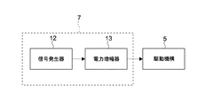
図2は、回路基板7の構成を示すブロック図である。回路基板7は、例えば正弦波等の電気信号を生成する信号発生器12と、信号発生器12から出力された電気信号の電力を増幅する電力増幅器13とを有する。電力増幅器13で増幅された電気信号は駆動機構5に入力される。
FIG. 2 is a block diagram showing the configuration of the
以上のように構成された噴流発生装置10の動作について説明する。
The operation of the jet
駆動機構5に、回路基板7によって例えば正弦波の交流電圧が印加されると、振動板3は正弦波振動を行う。これにより、チャンバ11内の容積が増減する。チャンバ11の容積変化に伴い、チャンバ11の圧力が変化することでノズル2から空気の流れが脈流として発生する。例えば、振動板3がチャンバ11の容積を増加させる方向に変位すると、チャンバ11の圧力は減少する。これによりノズル2を介して筐体1の外部の空気がチャンバ11内に流れ込む。逆に、振動板3がチャンバ11の容積を減少させる方向に変位すると、チャンバ11の圧力は増加する。これにより、チャンバ11内にある空気がノズル2を介して外部に吐出され、図示しない発熱体にその空気が吹き付けられる。ノズル2から空気が噴出されるときにノズル2の周囲の気圧が低下することにより、当該周囲の空気がノズル2から吐出される空気に巻き込まれる。すなわち、これが合成噴流である。このような合成噴流が、発熱体に吹き付けられることにより、発熱体を冷却することができる。
When, for example, a sine wave AC voltage is applied to the
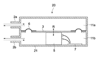
図3は、上記のチャンバが2つ形成された形態の噴流発生装置を示す断面図である。この噴流発生装置20では、筐体21内に設けられた、振動板3及び弾性支持部材6によりチャンバ11a及び11bが形成されている。チャンバ11aはノズル2aを介して筐体21の外部と連通している。チャンバ11bはノズル2bを介して筐体21の外部と連通している。このように構成された噴流発生装置20では、振動板3が図中上下に振動することにより、チャンバ11a及び11bの容積が交互に増減し、その結果、ノズル2a及び2bを介して交互に空気が吐出される。ノズル2a及び2bから空気が吐出されるときに、例えば各ノズル2a及びノズル2bから独立して音波が発生する。この音波は振動板3が振動することによる筐体21内の空気の振動によって発生する。しかしながら、各ノズル2a及びノズル2bとで発生する各音波は逆位相の音波であるため互いに弱められる。これにより、騒音が抑制され、静音化を図ることができる。
FIG. 3 is a cross-sectional view showing a jet flow generating apparatus in which two chambers are formed. In the
以上、図1または図3に示した振動板3を用いる噴流発生装置10または噴流発生装置20において、振動板3の有効面積をS [m2]、peak-to-peakの振幅をd[m]、振動周波数をf[Hz]としたとき、単位時間あたりの空気の吐出量Q[m3/s]は、次式で表される。
Q=k S d f
kは定数で、噴流発生装置10等の構造に依存するが、構造が同じであれば一定とみなすことができる。振動板3の振動周波数を固定した場合、振動板3の振幅を大きくすれば、振幅に比例して吐出量を大きくできる。一方、吐出量は周波数にも比例しているため、駆動周波数を高くするほど噴出量を大きくできる。しかしながらこのような機械振動系では一般に、振動の周波数を大きくするに従って振幅が減少するため、周波数を高くすればいくらでも吐出量を大きくできるわけではない。つまり吐出量が最大となる最適な周波数が存在する。この周波数は、噴流発生装置10等の大きさや構造、並びに振動板3の質量や弾性支持部材6の弾性特性、ノズル2内部の開口の大きさや形状に依存する。さらに排気側の負荷(放熱フィンの流路抵抗など)等にも依存する。
As described above, in the
Q = k S df
k is a constant and depends on the structure of the
しかしながら本発明者は、噴流発生装置10等の構成に依らず、この最適な周波数と、駆動機構5の入力インピーダンスとの間にある関係があることを見出した。すなわち、駆動機構5に印加する交流信号の電気的エネルギーを一定に保持しながら、その周波数を変えると、噴流発生装置10等からの空気吐出量が最大、すなわち熱抵抗が最低となる周波数は、駆動機構5の入力インピーダンスの大きさが極大となる周波数に一致することを本発明者は見出した。
However, the present inventor has found that there is a relationship between the optimum frequency and the input impedance of the
図4は、駆動機構5の駆動周波数と、熱抵抗及び入力インピーダンスとの関係示すグラフである。この図は、例えば図3に示した噴流発生装置20と、図示しない適当な放熱フィンとを組み合わせた放熱システムにおいて、駆動機構5が消費する電力を一定にしている。その消費電力は例えば0.5[W]であり、そのように電力を一定に維持しながら、入力周波数を10[Hz]から120[Hz]まで変えている。なお、振動板3としては、空気振動に寄与する面の直径が50[mm]程度のものが用いられた。
FIG. 4 is a graph showing the relationship between the drive frequency of the
このグラフから判るように、周波数が50〜60[Hz]あるいは50〜70[Hz]の領域において、駆動機構5の入力インピーダンスは最大に、熱抵抗は最低になっている。上記特許文献3、4に記載されているような、可聴周波数から外れた周波数(20[Hz]未満)では、熱抵抗が極めて高くなり放熱効率は悪化する。このように、駆動機構5を、その入力インピーダンスの大きさが最大となる周波数で駆動すれば、最小の消費電力で最大の放熱能力を持つ放熱システムを構成することができる。駆動機構5の入力インピーダンスの測定は、例えば定電圧駆動での電流値を測定することにより、噴流発生装置10の外部から簡単に行えるため、駆動周波数を入力インピーダンスの大きさが極大となる周波数近傍に調整することは容易である。
As can be seen from this graph, in the region where the frequency is 50 to 60 [Hz] or 50 to 70 [Hz], the input impedance of the
図5は、一般的な振動板(例えばスピーカ等)の周波数と、振幅、音圧レベル及び入力インピーダンスとの関係を示すグラフである。図5(A)を参照して、一般的なスピーカで使用される周波数帯域は、最低共振周波数f0より高いほぼ一定の音圧レベルの周波数帯域である。最低共振周波数f0より低い周波数では、振動板の振幅が周波数に依らず一定であるため、周波数が低くなるほど音圧が低下する。逆に最低共振周波数f0より高い周波数では周波数の2乗に反比例して振動板の振幅が低下するため、音圧は周波数に対してほぼ平坦になる。 FIG. 5 is a graph showing the relationship between the frequency of a general diaphragm (for example, a speaker, etc.), the amplitude, the sound pressure level, and the input impedance. Referring to FIG. 5A, the frequency band used in a general speaker is a frequency band having a substantially constant sound pressure level higher than the lowest resonance frequency f0. At a frequency lower than the lowest resonance frequency f0, the amplitude of the diaphragm is constant regardless of the frequency, so that the sound pressure decreases as the frequency decreases. Conversely, at a frequency higher than the lowest resonance frequency f0, the amplitude of the diaphragm decreases in inverse proportion to the square of the frequency, so that the sound pressure becomes substantially flat with respect to the frequency.
図5(B)を参照して、スピーカ等を振動させるボイスコイルの入力インピーダンスの極大Xとなる駆動周波数は、最低共振周波数f0近傍の周波数帯域にある。本実施の形態に係る噴流発生装置10等では、f0より低い周波数では振動板の振幅が一定であるため、周波数が低くなるほど空気の吐出量が低下する。f0より高い周波数では周波数の2乗に反比例して振幅が低下するため、周波数が高くなるほど空気の吐出量が低下する。したがってf0近傍の周波数で駆動することで最大の空気の吐出量が得られる。
Referring to FIG. 5B, the drive frequency at which the maximum impedance X of the input impedance of the voice coil that vibrates a speaker or the like is in the frequency band near the lowest resonance frequency f0. In the jet
以上のように、駆動機構5の入力インピーダンスが極大となる周波数で、駆動機構5を駆動することにより、限られた消費電力で最大の冷却効率で放熱システムを動作させることができる。
As described above, by driving the
さらに、噴流発生装置10または20の大きさや構造、並びに振動板の質量や弾性支持部材6の弾性特性、ノズル2内部の開口の大きさや形状、放熱フィンの流路抵抗等の構成材料のばらつきによって、最適な周波数に固体差が生じた場合であっても、常にその最適な周波数で駆動できる。したがって、性能のばらつきを発生させることなく、高い歩留まりで放熱システムを提供することができる。
Furthermore, depending on the size and structure of the jet
次に、図2に示した回路基板7の信号発生器12、電力増幅器13の具体的な構成や方式等の例について説明する。
Next, examples of specific configurations and systems of the
電力増幅器13は、電力増幅器の入力端子に印加された電圧に実質的に比例した電圧または電流を、電力増幅器13の出力端子に発生させる回路形式とすることができる。あるいは、電力増幅器13の入力端子間に流れる電流に実質的に比例した電圧または電流を、電力増幅器13の出力端子に発生させる回路形式とすることができる。すなわち、電力増幅器13は、電力増幅器13の出力端子に接続された負荷(駆動機構5の入力インピーダンス)の大きさに依らず、実質的に一定の電圧または電流を供給できる線形増幅器で構成することができる。
The
電力増幅器13の出力形式は、負荷の一端を接地電位で駆動させる単出力(SEEP:Single Ended Push Pull)方式でもよいが、負荷を2系統の電力増幅器で逆相駆動する両出力(BTL:Balanced Transformer less Amplifier)方式でもよい。また電力増幅器13の発振防止のために、CR直列回路やLR並列回路を付加的に挿入してもよい。
The output form of the
電力増幅器13として線形増幅器を用いることに加えて、図6に示すように、信号発生器としては、上述した正弦波信号を発生させる正弦波信号発生器22とすることができる。これは、時間に対して正弦波状に変化する電圧または電流信号をその出力端子に生成し、正弦波信号発生器22が生成する正弦波状の信号の基本周波数は、上記駆動機構5の入力インピーダンスが極大となる周波数近傍に設定されている。すなわち、上記駆動機構5の入力インピーダンスが極大となる周波数近傍の周波数を持つ正弦波状信号を生成し、その信号波形を実質的に保持したまま、駆動機構5を駆動する。
In addition to using a linear amplifier as the
正弦波信号発生器22としては、例えばCR型発振器が挙げられる。CR型発振器とは、キャパシタと抵抗による時定数を利用した発振器である、ウイーンブリッジ型、状態変数型、移相型などがあるが、発振周波数を外部から比較的容易に制御できるものであればいずれの方式でもよい。
An example of the sine
正弦波信号発生器22がCR型発振器の場合、出力信号の全高調波歪率が10%未満であることが好ましい。CR型発振器の出力信号は上記線形電力増幅器を通じて、駆動機構5に入力されるため、当該発振器の波形が実質的に保存されたまま、駆動機構5に入力される。振動板3の変位量は、駆動機構5の入力電流の大きさに実質的に比例しているため、駆動機構5の入力信号に高調波成分が多く含まれると、振動板3の振動に含まれる高調波成分も大きくなる。この高調波成分が、聴感度の高い周波数成分を含む場合、騒音レベルが高くなるおそれがある。したがって、CR型発振器の出力信号は、全高調波歪率がなるべく小さい正弦波信号を用いるべきである。全高調波歪率が10%未満であれば、通常の動作条件では騒音は気にならない。CR型発振器の場合、適切な利得制限回路等を用いれば、このような歪率は比較的容易に実現することができる。
When the sine
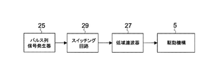
図7(A)は、上記正弦波信号発生器22として、矩形波、三角波、あるいはのこぎり波の信号を発生する信号発生器23が用いられている。そして、矩形波/三角波/のこぎり波信号発生器23の出力信号を、高調波成分を低減させるための、低域濾波器(Low Pass Filter)27に通すことで、高調波成分が小さい低歪の正弦波状信号を得ることができる。矩形波/三角波/のこぎり波信号発生器23は、上述のCR型で一般的に知られる回路形式を利用すればよい。
In FIG. 7A, a
低域濾波器27の特性としては、高調波の振幅を1/10未満に減衰させることが望ましい。このような低域濾波器27は、減衰特性に優れたアクティブフィルタまたはスイッチドキャパシタフィルタを用いることがさらに望ましい。フィルタの次数や特性(ベッセル型、バタワース型、チェビシェフ形など)は、必要な出力歪率に応じて適宜選択すればよい。
As a characteristic of the low-
一方、正弦波状の信号発生器として、CR型を含むアナログ回路ではなく、デジタル回路を用いてもよい。例えば図7(B)に示すように、正弦波の振幅をデジタル化した信号を発生させる振幅データ発生器24と、当該振幅データを電圧または電流の大きさに変換するD/A(Digital-to-Analog)変換器28とが用いられる。振幅データ発生器24の基準クロックの周波数を変えることにより、D/A変換器28から出力される正弦波状信号の周波数を制御することができる。
On the other hand, as a sinusoidal signal generator, a digital circuit may be used instead of an analog circuit including a CR type. For example, as shown in FIG. 7B, an
振幅データ発生器24は、振幅データをあらかじめ格納した固体メモリを利用してもよいし、デジタル演算によって正弦関数データを発生させる構成でもよい。またデジタルデータのビット数やサンプリング数も、必要な歪率に応じて適宜選択すればよい。デジタル的に生成された正弦波状信号には、サンプリング周波数による量子雑音が含まれるが、これを低減させるために、D/A変換器28と電力増幅器13との間に、アナログあるいはデジタル回路で構成された低域濾波器を入れてもよい。
The
さらに、デジタル型の正弦波の信号発生器として、図7(C)に示すような、パルス列信号発生器25を用いることもできる。正弦波信号発生器22は、このような時間に対して断続的に電圧が変化する電圧パルス列、あるいは時間に対して断続的に電流が変化する電流パルス列を生成するパルス列信号発生器25と、低域濾波器27とから構成される。D/A変換器を用いた正弦波信号発生器では、D/A変換器の出力波形は、駆動機構5に入力される信号の波形に類似して変化するが、パルス列信号発生器25が生成する信号は、振幅が実質的に一定で、電圧または電流パルスの断続時間が変化する。これらの信号を低域濾波器27に通すことによって、このパルス列の高周波成分が減衰し、連続波状の信号に整形される。パルス列のパルス幅や周期を調整することにより、低域濾波器27の出力に正弦波信号を出力させることができる。パルス列信号発生器25に与える基準クロック周波数を変えることにより、その正弦波状の信号の周波数を制御することができる。
Further, a pulse
パルス列信号発生器25で発生させるパルス列としては、パルス幅が一定で、パルス間隔が変化するパルス列を出力することができる、あるいは、パルス列としては、周期が一定で、パルス幅が変化するパルス幅変調されたパルス列であってもよい。いずれのパルス列でも、パルス幅と周期との比率を、サンプリング周期毎に適切に制御することにより、低域濾波器27の出力に正弦波信号を出力させることができる。なお、パルス列信号発生器25で発生させるパルス列は、その振幅(電圧または電流)が一定であってもよいが、時間に関して変化するような信号でもよい。
As the pulse train generated by the pulse
図7(A)〜図7(C)で説明した電力増幅器13は、その出力端子に接続された負荷(駆動機構5の入力インピーダンス)の大きさに依らず、実質的に一定の電圧または電流を供給できる線形増幅器であった。しかし、図8に示すように、この電力増幅器13は非線形の増幅器、またはスイッチング回路29とする構成も考えられる。
The
このようにスイッチング回路29を用いる場合、信号発生器は、上記パルス列信号発生器25を用いることができる。つまり、これにより生成されるパルス列の基本周波数が、上記駆動機構5の入力インピーダンスが極大となる周波数近傍に設定される。増幅器となるスイッチング回路29は、入力信号に同期した電圧パルスまたは電流パルスを、出力端子に発生させる。低域濾波器27はパルス列信号に含まれる量子雑音が小さい場合は省略することができる。
When the switching
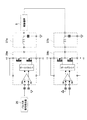
図9に、図8に示したスイッチング回路29の構成例を示す。この構成は、駆動機構5の入力端子の一方を接地電位で駆動する例である。パルス列信号発生器25からのパルス列信号が、スイッチング回路29の差動増幅器に入力されると、そのタイミングに同期したデジタル信号に変換される。差動増幅器の非反転出力と反転出力がゲートドライバに入力され、スイッチング素子(MOS-FET)のON/OFFに必要なタイミング信号が生成される。スイッチング素子は、例えば、差動増幅器にパルス信号が入力された時に一方がONし、他方はOFFとなるように動作する。差動増幅器にパルス信号が入力されていない時には、逆に一方はOFFとなり、他方はONとなる。これにより、スイッチング回路29の出力には、パルス列信号発生器25からのパルス列信号と同期した信号が出力される。この信号には多くの高調波成分が含まれているので、必要に応じて、例えばインダクタとキャパシタからなる低域濾波器27を用いて高調波成分を減衰させる。これにより、駆動機構5の入力端子に、正弦波信号を印加することができる。
FIG. 9 shows a configuration example of the switching
図10は、パルス列信号発生器25の出力を2つのスイッチング回路29a及び29bに入力させる例を示す。2つのスイッチング回路29a及び29bは、図9に示したスイッチング回路29とそれぞれ同様の構成であり、これらの出力には低域濾波器27a及び27bが接続されている。このような構成によれば、図9で示した場合と同じ電源電圧(V+、V−)で、2倍の振幅を得ることができる。
FIG. 10 shows an example in which the output of the pulse
1、21…筐体
2…ノズル
2a…ノズル
2b…ノズル
3…振動板
5…駆動機構
7…回路基板
10、20…噴流発生装置
12…信号発生器
13…電力増幅器
22…正弦波信号発生器
DESCRIPTION OF
Claims (4)
前記筐体に振動可能に支持され、前記気体に振動を与えることで、前記開口を介して前記気体を脈流として吐出させるための振動体と、
電気信号に応じて前記振動体を駆動するための駆動機構と、
噴流発生装置と前記気体が吹き付けられる発熱体とを含む放熱システムの熱抵抗が最低となる周波数であって前記駆動機構の入力インピーダンスが極大となるような基本周波数を含む周波数帯域で電気信号を生成して前記駆動機構に出力する駆動制御部と
を具備する噴流発生装置。 A housing having an opening and containing gas inside;
A vibrating body supported by the housing so as to be able to vibrate, and causing the gas to be discharged as a pulsating flow through the opening by giving vibration to the gas,
A drive mechanism for driving the vibrating body in response to an electrical signal;
An electric signal in a frequency band including the fundamental frequency as the input impedance of the driving mechanism thermal resistance of the heat dissipation system comprising a heating element wherein the jet flow generating device gas is blown is a frequency at which the lowest is extremely large And a drive control unit that generates and outputs the drive mechanism to the drive mechanism.
前記駆動制御部は、
増幅器と、
前記駆動機構の入力インピーダンスが極大となるような基本周波数を有する正弦波、電圧パルス、または電流パルスの信号を生成する信号発生器とを有し、
前記増幅器は、前記生成された信号を増幅して前記駆動機構に出力する
噴流発生装置。 The jet generator according to claim 1,
The drive control unit
An amplifier;
And a signal generator for the input impedance of the driving mechanism for generating a signal of sinusoidal, voltage or current pulse, having a fundamental frequency such that pole large,
The amplifier amplifies the generated signal and outputs the amplified signal to the drive mechanism.
前記信号発生器は、前記電気信号の全高調波歪率が10%未満である
噴流発生装置。 The jet generating device according to claim 2,
The signal generator has a total harmonic distortion of the electric signal of less than 10%.
開口を有し、内部に気体が含まれた筐体と、
前記筐体に振動可能に支持され、前記気体に振動を与えることで、前記開口を介して前記気体を前記発熱体に向けて脈流として吐出させるための振動体と、
電気信号に応じて前記振動体を駆動するための駆動機構と、
噴流発生装置と前記気体が吹き付けられる発熱体とを含む放熱システムの熱抵抗が最低となる周波数であって前記駆動機構の入力インピーダンスが極大となるような基本周波数を含む周波数帯域で電気信号を生成して前記駆動機構に出力する駆動制御部と
を具備する電子機器。 A heating element;
A housing having an opening and containing gas inside;
A vibrating body supported by the housing so as to vibrate, and by causing the gas to vibrate, to discharge the gas as a pulsating flow toward the heating element through the opening;
A drive mechanism for driving the vibrating body in response to an electrical signal;
An electric signal in a frequency band including the fundamental frequency as the input impedance of the driving mechanism thermal resistance of the heat dissipation system comprising a heating element wherein the jet flow generating device gas is blown is a frequency at which the lowest is extremely large An electronic device comprising: a drive control unit that generates and outputs to the drive mechanism.
Priority Applications (6)
| Application Number | Priority Date | Filing Date | Title |
|---|---|---|---|
| JP2005123656A JP4887652B2 (en) | 2005-04-21 | 2005-04-21 | Jet generator and electronic device |
| EP20060008112 EP1715519B1 (en) | 2005-04-21 | 2006-04-19 | Jet generating device and electronic apparatus |
| US11/379,498 US7682137B2 (en) | 2005-04-21 | 2006-04-20 | Jet generating device and electronic apparatus |
| TW095114047A TW200642764A (en) | 2005-04-21 | 2006-04-20 | Jet generating device and electronic apparatus |
| KR1020060035658A KR101217362B1 (en) | 2005-04-21 | 2006-04-20 | Jet generating device and electronic apparatus |
| CNB2006100746703A CN100437998C (en) | 2005-04-21 | 2006-04-21 | Jet generating device and electronic apparatus |
Applications Claiming Priority (1)
| Application Number | Priority Date | Filing Date | Title |
|---|---|---|---|
| JP2005123656A JP4887652B2 (en) | 2005-04-21 | 2005-04-21 | Jet generator and electronic device |
Publications (2)
| Publication Number | Publication Date |
|---|---|
| JP2006299962A JP2006299962A (en) | 2006-11-02 |
| JP4887652B2 true JP4887652B2 (en) | 2012-02-29 |
Family
ID=36679054
Family Applications (1)
| Application Number | Title | Priority Date | Filing Date |
|---|---|---|---|
| JP2005123656A Expired - Fee Related JP4887652B2 (en) | 2005-04-21 | 2005-04-21 | Jet generator and electronic device |
Country Status (6)
| Country | Link |
|---|---|
| US (1) | US7682137B2 (en) |
| EP (1) | EP1715519B1 (en) |
| JP (1) | JP4887652B2 (en) |
| KR (1) | KR101217362B1 (en) |
| CN (1) | CN100437998C (en) |
| TW (1) | TW200642764A (en) |
Families Citing this family (31)
| Publication number | Priority date | Publication date | Assignee | Title |
|---|---|---|---|---|
| US7471827B2 (en) | 2003-10-16 | 2008-12-30 | Microsoft Corporation | Automatic browsing path generation to present image areas with high attention value as a function of space and time |
| JP4279662B2 (en) * | 2003-12-26 | 2009-06-17 | アルプス電気株式会社 | Small pump |
| JP2006310586A (en) | 2005-04-28 | 2006-11-09 | Sony Corp | Air current generator and electronic apparatus |
| US20080137289A1 (en) * | 2006-12-08 | 2008-06-12 | General Electric Company | Thermal management system for embedded environment and method for making same |
| JP2008280917A (en) * | 2007-05-10 | 2008-11-20 | Alps Electric Co Ltd | Piezoelectric gas injection device |
| JP4826956B2 (en) * | 2007-05-24 | 2011-11-30 | Necディスプレイソリューションズ株式会社 | Cooling device, electronic device equipped with cooling device, and projection display device |
| RU2501982C2 (en) * | 2007-12-07 | 2013-12-20 | Конинклейке Филипс Электроникс Н.В. | Cooling device with low noise level |
| CN103527452A (en) * | 2008-06-03 | 2014-01-22 | 株式会社村田制作所 | Piezoelectric micro-blower |
| CN102150485A (en) * | 2008-09-12 | 2011-08-10 | 皇家飞利浦电子股份有限公司 | Device provided with a gap-like space and a synthetic jet generator coupled there-to |
| EP2380074B1 (en) * | 2008-12-19 | 2016-11-16 | Koninklijke Philips N.V. | Apparatus and method for providing a user interface to an information processing system |
| US8371829B2 (en) * | 2010-02-03 | 2013-02-12 | Kci Licensing, Inc. | Fluid disc pump with square-wave driver |
| US20120170216A1 (en) * | 2011-01-04 | 2012-07-05 | General Electric Company | Synthetic jet packaging |
| EP2743505B1 (en) * | 2011-06-20 | 2019-11-13 | Mitsubishi Electric Corporation | Fluid conveying device |
| AU2013216990A1 (en) * | 2012-02-10 | 2014-07-24 | Kci Licensing, Inc. | Systems and methods for regulating the temperature of a disc pump system |
| TWI475180B (en) | 2012-05-31 | 2015-03-01 | Ind Tech Res Inst | Synthetic jet equipment |
| US9638182B2 (en) * | 2013-03-13 | 2017-05-02 | Clean Energy Labs, Llc | Graphene-trough pump systems |
| US9976762B2 (en) * | 2013-03-14 | 2018-05-22 | General Electric Company | Synthetic jet driven cooling device with increased volumetric flow |
| US20150041104A1 (en) * | 2013-08-09 | 2015-02-12 | Ge Aviation Systems, Llc | Systems and methods for robust and modular synthetic jet cooling |
| CN104320934A (en) * | 2014-10-23 | 2015-01-28 | 重庆金宏汽车电子有限公司 | Vehicle navigator good in heat dissipation performance |
| US20170333737A1 (en) * | 2014-12-19 | 2017-11-23 | Koninklijke Philips N.V. | Wearable air purification device |
| US9559037B2 (en) | 2015-06-02 | 2017-01-31 | Intel Corporation | Package integrated synthetic jet device |
| DE112016004072B4 (en) * | 2015-10-05 | 2023-12-07 | Murata Manufacturing Co., Ltd. | FLUID CONTROL DEVICE, DECOMPRESSION DEVICE AND COMPRESSION DEVICE |
| TWI624595B (en) * | 2016-11-17 | 2018-05-21 | 英業達股份有限公司 | Airflow generating device and airflow generating method |
| CN108076256A (en) * | 2016-11-18 | 2018-05-25 | 天津嘉深保科技发展有限公司 | A kind of market survey service camera |
| JP6804282B2 (en) * | 2016-12-08 | 2020-12-23 | M&D Innovations株式会社 | Oscillator drive device and vibration generator |
| JP7219722B2 (en) * | 2017-12-26 | 2023-02-08 | 株式会社村田製作所 | pumping equipment |
| JP6705440B2 (en) * | 2017-12-28 | 2020-06-03 | Tdk株式会社 | Driving method for tactile presentation device |
| CN108933114B (en) * | 2018-07-18 | 2020-01-07 | 江苏森德邦信息科技有限公司 | Heat radiator for be used for small-size electrical components of alternating current |
| US11218809B2 (en) * | 2018-10-05 | 2022-01-04 | Netgear, Inc. | Speaker integrated electronic device with speaker driven passive cooling |
| CN110332185A (en) * | 2019-06-27 | 2019-10-15 | 中国科学院力学研究所 | A kind of gaseous jet flow control method and system |
| CN115642379B (en) * | 2022-10-12 | 2023-09-05 | 中节能风力发电股份有限公司 | Physical low-pass filter of fan low-frequency vibration sensor |
Family Cites Families (33)
| Publication number | Priority date | Publication date | Assignee | Title |
|---|---|---|---|---|
| US3373752A (en) * | 1962-11-13 | 1968-03-19 | Inoue Kiyoshi | Method for the ultrasonic cleaning of surfaces |
| US4350838A (en) * | 1980-06-27 | 1982-09-21 | Electric Power Research Institute, Inc. | Ultrasonic fluid-atomizing cooled power transformer |
| JPH02213200A (en) | 1989-02-14 | 1990-08-24 | Victor Co Of Japan Ltd | Heat exchanger |
| JPH03116961A (en) | 1989-09-29 | 1991-05-17 | Victor Co Of Japan Ltd | Heat dissipating device |
| JPH03148911A (en) * | 1989-11-02 | 1991-06-25 | Victor Co Of Japan Ltd | Signal generation equipment and blowing device using signal generation equipment |
| CH689836A5 (en) * | 1994-01-14 | 1999-12-15 | Westonbridge Int Ltd | Micropump. |
| DE4402119C2 (en) * | 1994-01-25 | 1998-07-23 | Karlsruhe Forschzent | Process for the production of micromembrane pumps |
| BR9404646A (en) * | 1994-12-02 | 1997-03-04 | Brasil Compressores Sa | Hermetic compressor for cooling system |
| US6123145A (en) * | 1995-06-12 | 2000-09-26 | Georgia Tech Research Corporation | Synthetic jet actuators for cooling heated bodies and environments |
| US5919582A (en) * | 1995-10-18 | 1999-07-06 | Aer Energy Resources, Inc. | Diffusion controlled air vent and recirculation air manager for a metal-air battery |
| JP3812917B2 (en) * | 1997-05-14 | 2006-08-23 | 本田技研工業株式会社 | Piezoelectric actuator |
| US5861703A (en) * | 1997-05-30 | 1999-01-19 | Motorola Inc. | Low-profile axial-flow single-blade piezoelectric fan |
| US6254556B1 (en) * | 1998-03-12 | 2001-07-03 | Craig N. Hansen | Repetitive pressure pulse jacket |
| JP2000023300A (en) * | 1998-07-06 | 2000-01-21 | Victor Co Of Japan Ltd | Automatic sound system setting device |
| JP3359301B2 (en) * | 1999-06-04 | 2002-12-24 | 松下電器産業株式会社 | Noise control device |
| JP3525757B2 (en) * | 1998-09-18 | 2004-05-10 | 株式会社日立製作所 | Chemical analyzer |
| GB2343122B (en) | 1998-10-26 | 2003-01-08 | Medic Aid Ltd | Improvements in and relating to nebulisers |
| KR20000050679A (en) * | 1999-01-13 | 2000-08-05 | 윤종용 | Heat sinking apparatus for electronic equipment |
| US6353295B1 (en) * | 1999-01-20 | 2002-03-05 | Philips Electronics North America Corporation | Lamp electronic ballast with a piezoelectric cooling fan |
| JP3415489B2 (en) * | 1999-06-21 | 2003-06-09 | 昌廣 羽瀬 | Air pump device |
| FR2798232B1 (en) * | 1999-09-03 | 2001-11-16 | Elf Exploration Prod | ELECTRIC AC MOTOR |
| WO2002022358A1 (en) * | 2000-09-18 | 2002-03-21 | Par Technologies, Llc. | Piezoelectric actuator and pump using same |
| US7198250B2 (en) * | 2000-09-18 | 2007-04-03 | Par Technologies, Llc | Piezoelectric actuator and pump using same |
| US6484521B2 (en) * | 2001-02-22 | 2002-11-26 | Hewlett-Packard Company | Spray cooling with local control of nozzles |
| US20020155010A1 (en) * | 2001-04-24 | 2002-10-24 | Karp Christoph D. | Microfluidic valve with partially restrained element |
| US6588497B1 (en) | 2002-04-19 | 2003-07-08 | Georgia Tech Research Corporation | System and method for thermal management by synthetic jet ejector channel cooling techniques |
| US7011507B2 (en) * | 2002-06-04 | 2006-03-14 | Seiko Epson Corporation | Positive displacement pump with a combined inertance value of the inlet flow path smaller than that of the outlet flow path |
| GB2419644B (en) | 2003-07-07 | 2008-04-09 | Georgia Tech Res Inst | System and method for thermal management using distributed synthetic jet actuators |
| DE602004003316T2 (en) * | 2003-09-12 | 2007-03-15 | Samsung Electronics Co., Ltd., Suwon | Diaphragm pump for cooling air |
| US7240500B2 (en) | 2003-09-17 | 2007-07-10 | Hewlett-Packard Development Company, L.P. | Dynamic fluid sprayjet delivery system |
| US7284966B2 (en) * | 2003-10-01 | 2007-10-23 | Agency For Science, Technology & Research | Micro-pump |
| US7290993B2 (en) * | 2004-04-02 | 2007-11-06 | Adaptivenergy Llc | Piezoelectric devices and methods and circuits for driving same |
| US20070217929A1 (en) * | 2006-03-17 | 2007-09-20 | Jackey Chiou | Diaphragm pumping device |
-
2005
- 2005-04-21 JP JP2005123656A patent/JP4887652B2/en not_active Expired - Fee Related
-
2006
- 2006-04-19 EP EP20060008112 patent/EP1715519B1/en not_active Not-in-force
- 2006-04-20 KR KR1020060035658A patent/KR101217362B1/en not_active IP Right Cessation
- 2006-04-20 US US11/379,498 patent/US7682137B2/en not_active Expired - Fee Related
- 2006-04-20 TW TW095114047A patent/TW200642764A/en not_active IP Right Cessation
- 2006-04-21 CN CNB2006100746703A patent/CN100437998C/en not_active Expired - Fee Related
Also Published As
| Publication number | Publication date |
|---|---|
| TWI291896B (en) | 2008-01-01 |
| EP1715519A2 (en) | 2006-10-25 |
| US7682137B2 (en) | 2010-03-23 |
| US20060239844A1 (en) | 2006-10-26 |
| KR20060110816A (en) | 2006-10-25 |
| KR101217362B1 (en) | 2012-12-31 |
| TW200642764A (en) | 2006-12-16 |
| JP2006299962A (en) | 2006-11-02 |
| CN1855458A (en) | 2006-11-01 |
| CN100437998C (en) | 2008-11-26 |
| EP1715519A3 (en) | 2007-12-19 |
| EP1715519B1 (en) | 2011-09-21 |
Similar Documents
| Publication | Publication Date | Title |
|---|---|---|
| JP4887652B2 (en) | Jet generator and electronic device | |
| KR101164257B1 (en) | Gas jetting device, electronic device and gas jetting method | |
| JP4747657B2 (en) | Jet generator and electronic device | |
| US7861767B2 (en) | Airflow generating device and electronic apparatus | |
| TWI524840B (en) | Heat dissipating module | |
| US7688583B1 (en) | Synthetic jet and method of making same | |
| US8033324B2 (en) | Jet flow generating apparatus, electronic apparatus, and jet flow generating method | |
| KR102073199B1 (en) | Multi-function synthetic jet and method of manufacturing same | |
| CN100442200C (en) | Vibrating device for jet flow generating including a voice coil motor | |
| JP2008167252A (en) | Thermal excitation type sound wave generator | |
| US20020175597A1 (en) | Piezoelectric device with feedback sensor | |
| JP2007518910A (en) | Medium flow generator | |
| JP5003018B2 (en) | Jet generator | |
| JP2007222727A (en) | Vibration actuator and jet generator | |
| JP2007209845A (en) | Jet flow generator and electronic apparatus | |
| JP4900503B2 (en) | Gas ejection device and electronic device | |
| JP2006063900A (en) | Jet generating device and electronic apparatus | |
| JP2012217012A (en) | Electronic apparatus | |
| JP2012038788A (en) | Cooling use piezoelectric actuator drive circuit | |
| JP2007154784A (en) | Jet generating device and electronic apparatus |
Legal Events
| Date | Code | Title | Description |
|---|---|---|---|
| A621 | Written request for application examination |
Free format text: JAPANESE INTERMEDIATE CODE: A621 Effective date: 20080311 |
|
| A977 | Report on retrieval |
Free format text: JAPANESE INTERMEDIATE CODE: A971007 Effective date: 20100930 |
|
| A131 | Notification of reasons for refusal |
Free format text: JAPANESE INTERMEDIATE CODE: A131 Effective date: 20101026 |
|
| A521 | Request for written amendment filed |
Free format text: JAPANESE INTERMEDIATE CODE: A523 Effective date: 20101222 |
|
| A131 | Notification of reasons for refusal |
Free format text: JAPANESE INTERMEDIATE CODE: A131 Effective date: 20110607 |
|
| A521 | Request for written amendment filed |
Free format text: JAPANESE INTERMEDIATE CODE: A523 Effective date: 20110610 |
|
| TRDD | Decision of grant or rejection written | ||
| A01 | Written decision to grant a patent or to grant a registration (utility model) |
Free format text: JAPANESE INTERMEDIATE CODE: A01 Effective date: 20111115 |
|
| A01 | Written decision to grant a patent or to grant a registration (utility model) |
Free format text: JAPANESE INTERMEDIATE CODE: A01 |
|
| A61 | First payment of annual fees (during grant procedure) |
Free format text: JAPANESE INTERMEDIATE CODE: A61 Effective date: 20111128 |
|
| FPAY | Renewal fee payment (event date is renewal date of database) |
Free format text: PAYMENT UNTIL: 20141222 Year of fee payment: 3 |
|
| R250 | Receipt of annual fees |
Free format text: JAPANESE INTERMEDIATE CODE: R250 |
|
| LAPS | Cancellation because of no payment of annual fees |