JP4747657B2 - Jet generator and electronic device - Google Patents
Jet generator and electronic device Download PDFInfo
- Publication number
- JP4747657B2 JP4747657B2 JP2005123432A JP2005123432A JP4747657B2 JP 4747657 B2 JP4747657 B2 JP 4747657B2 JP 2005123432 A JP2005123432 A JP 2005123432A JP 2005123432 A JP2005123432 A JP 2005123432A JP 4747657 B2 JP4747657 B2 JP 4747657B2
- Authority
- JP
- Japan
- Prior art keywords
- opening
- chamber
- khz
- housing
- openings
- Prior art date
- Legal status (The legal status is an assumption and is not a legal conclusion. Google has not performed a legal analysis and makes no representation as to the accuracy of the status listed.)
- Expired - Fee Related
Links
Images


Classifications
-
- G—PHYSICS
- G06—COMPUTING; CALCULATING OR COUNTING
- G06F—ELECTRIC DIGITAL DATA PROCESSING
- G06F1/00—Details not covered by groups G06F3/00 - G06F13/00 and G06F21/00
- G06F1/16—Constructional details or arrangements
- G06F1/20—Cooling means
-
- H—ELECTRICITY
- H02—GENERATION; CONVERSION OR DISTRIBUTION OF ELECTRIC POWER
- H02K—DYNAMO-ELECTRIC MACHINES
- H02K33/00—Motors with reciprocating, oscillating or vibrating magnet, armature or coil system
- H02K33/18—Motors with reciprocating, oscillating or vibrating magnet, armature or coil system with coil systems moving upon intermittent or reversed energisation thereof by interaction with a fixed field system, e.g. permanent magnets
-
- G—PHYSICS
- G06—COMPUTING; CALCULATING OR COUNTING
- G06F—ELECTRIC DIGITAL DATA PROCESSING
- G06F1/00—Details not covered by groups G06F3/00 - G06F13/00 and G06F21/00
-
- H—ELECTRICITY
- H01—ELECTRIC ELEMENTS
- H01L—SEMICONDUCTOR DEVICES NOT COVERED BY CLASS H10
- H01L2924/00—Indexing scheme for arrangements or methods for connecting or disconnecting semiconductor or solid-state bodies as covered by H01L24/00
- H01L2924/0001—Technical content checked by a classifier
- H01L2924/0002—Not covered by any one of groups H01L24/00, H01L24/00 and H01L2224/00
Description
本発明は、気体の噴流を発生させる噴流発生装置及びこの噴流発生装置を搭載した電子機器に関する。 The present invention relates to a jet generating device that generates a jet of gas and an electronic apparatus equipped with the jet generating device.
従来から、PC(Personal Computer)の高性能化に伴うIC(Integrated Circuit)等の発熱体からの発熱量の増大が問題となっており、様々な放熱の技術が提案され、あるいは製品化されている。その放熱方法として、例えばICにアルミなどの金属でなる放熱用のフィンを接触させて、ICからの熱をフィンに伝導させて放熱する方法がある。また、ファンを用いることにより、例えばPCの筐体内の温まった空気を強制的に排除し、周囲の低温の空気を発熱体周辺に導入することで放熱する方法もある。あるいは放熱フィンとファンとを併用することにより、放熱フィンで発熱体と空気の接触面積を大きくしつつ、ファンにより放熱フィンの周囲の暖まった空気を強制的に排除する方法もある。 Conventionally, an increase in the amount of heat generated from a heating element such as an IC (Integrated Circuit) associated with high performance of a PC (Personal Computer) has been a problem, and various heat radiation technologies have been proposed or commercialized. Yes. As a heat dissipation method, for example, there is a method in which a heat dissipation fin made of a metal such as aluminum is brought into contact with the IC, and heat from the IC is conducted to the fin to dissipate heat. Also, there is a method of dissipating heat by forcibly removing, for example, warm air in a PC housing by using a fan and introducing ambient low-temperature air around the heating element. Alternatively, there is a method of forcibly removing the warm air around the radiating fin by the fan while using the radiating fin and the fan together to increase the contact area between the heating element and the air with the radiating fin.
しかしながら、このようなファンによる空気の強制対流では、放熱フィンの下流側でフィン表面の温度境界層が生起され、放熱フィンからの熱を効率的に奪えないという問題がある。このような問題を解決するためには、例えばファンの風速を上げて温度境界層を薄くすることが挙げられる。しかし、風速を上げるためにファンの回転数を増加させることにより、ファンの軸受け部分からの騒音や、ファンからの風が引き起こす風切り音などによる騒音が発生するという問題がある。 However, in such forced convection of air by the fan, there is a problem that a temperature boundary layer on the surface of the fin occurs on the downstream side of the radiating fin, and heat from the radiating fin cannot be efficiently taken. In order to solve such a problem, for example, the temperature of the temperature boundary layer can be reduced by increasing the wind speed of the fan. However, increasing the number of rotations of the fan in order to increase the wind speed has a problem in that noise from the bearing portion of the fan or noise due to wind noise caused by the wind from the fan occurs.
一方、送風手段としてファンを用いずに、上記温度境界層を破壊し、放熱フィンからの熱を効率よく外気に逃がす方法として、周期的に往復運動する振動板を用いる方法がある(例えば特許文献1、2、3、4参照)。これらの装置のうち、特に特許文献3及び4の装置は、チャンバ内を空間的に概略二分する振動板と、振動板を支持しチャンバに設けられた弾性体と、振動板を振動させる手段とを備えている。これらの装置では、例えば振動板が上方向に変位したときには、チャンバの上部空間の体積が減少するため、上部空間の圧力が上昇する。上部空間は吸排気口を通じて外気と連通しているため、上部空間の圧力上昇によって、その内部の空気の一部が外気中に放出される。一方このとき、振動板を挟んで上部空間と反対側にある下部空間の体積は逆に増加するため、下部空間の圧力が下降する。下部空間は吸排気口を通じて外気と連通しているため、下部空間の圧力減少によって、吸排気口近傍にある外気の一部が下部空間内部に引き込まれる。これとは逆に、振動板が下方向に変位したときには、チャンバの上部空間の体積が増加するため、上部空間の圧力が下降する。上部空間は吸排気口を通じて外気と連通しているため、上部空間の圧力下降によって、吸排気口近傍にある外気の一部が上部空間内部に引き込まれる。一方このとき、振動板を挟んで上部空間と反対側にある下部空間の体積は逆に減少するため、下部空間の圧力は上昇する。下部空間の圧力上昇によって、その内部の空気の一部が外気中に放出される。振動板の駆動は例えば電磁駆動方式が用いられる。このように、振動板を往復運動させることによって、チャンバ内の空気が外気に排出される動作と、外気がチャンバ内に吸気される動作が周期的に繰り返される。このような、振動板の周期的な往復運動によって誘起される空気の脈流が放熱フィン(ヒートシンク)等の発熱体に吹き付けられることにより、放熱フィンの表面にある温度境界層が効率よく破壊され、結果的に放熱フィンが効率良く冷却される。
近年のICの高クロック化によって発生する熱量は増加の一途をたどっている。したがって、例えばその発熱によって放熱フィン付近に形成される温度境界層を破壊するためには、そのICや放熱フィンに向けてこれまでより多量の空気を送り込まなければならない。上記特許文献1〜4に記載されているような、周期的に往復運動する振動板を用いる空気排出方法では、振動板の振幅を大きくすることによって空気の吐出量を大きくすることができる。しかしながら、振動板の振幅を大きくするほど騒音が大きくなるという問題があり、実用的には、騒音が気にならないような小さな振幅で動作させなければならない。 The amount of heat generated by the recent increase in the clock frequency of ICs continues to increase. Therefore, for example, in order to destroy the temperature boundary layer formed in the vicinity of the radiating fin due to the heat generation, a larger amount of air has to be sent toward the IC and the radiating fin. In the air discharge method using the diaphragm that reciprocates periodically as described in Patent Documents 1 to 4, the discharge amount of air can be increased by increasing the amplitude of the diaphragm. However, there is a problem that noise increases as the amplitude of the diaphragm increases, and in practice, it must be operated with a small amplitude that does not bother the noise.
この騒音の原因の1つは、振動板の往復運動によってチャンバ内の気圧が周期的に変動することで発生する音波である。この音波がチャンバの壁面を振動させたり、あるいは、吸排気口を通じて音波が外気中に伝搬したりすることにより、外気中に、振動板の振動周波数と同じ周波数の音波が放出される。したがって振幅を大きくするほどこの音による騒音が問題となる。 One of the causes of this noise is a sound wave generated when the atmospheric pressure in the chamber fluctuates periodically due to the reciprocating motion of the diaphragm. When the sound wave vibrates the wall surface of the chamber or the sound wave propagates into the outside air through the intake / exhaust port, a sound wave having the same frequency as the vibration frequency of the diaphragm is emitted into the outside air. Therefore, the noise becomes more problematic as the amplitude is increased.
騒音のもう1つの原因は、振動板の往復運動によって発生する空気の流れの乱れによる気流音である。振幅を大きくするほど、往復運動する空気の最大流速が大きくなるため、チャンバ内部にあって、空気の滑らかな流れを阻害する構造体(例えば、駆動手段や吸排気口)によって発生する空気流の乱れ、あるいは吸排気口を高速で通過する空気流や吸排気口外部の空気流の乱れによって生起された気流音による騒音が問題となる。 Another cause of noise is airflow noise caused by air flow turbulence generated by the reciprocating motion of the diaphragm. As the amplitude is increased, the maximum flow velocity of the reciprocating air is increased. Therefore, the air flow generated by a structure (for example, a drive unit or an intake / exhaust port) in the chamber that obstructs the smooth flow of air. Noise due to turbulence or airflow noise caused by turbulence or airflow passing through the intake / exhaust port at high speed or turbulence of airflow outside the intake / exhaust port becomes a problem.
振動板の往復運動による空気振動が音波となって生ずる騒音は、例えば特許文献3及び4に記載されているように(特許文献3及び4のそれぞれの第2頁左下欄)、振動の周波数を可聴域から離すことによって低減できるが、周波数を下げるほど単位時間あたりの空気排出量が少なくなってしまう(空気排出量は振動板の振幅、有効断面積及び周波数の積に比例する)。逆に可聴域外の高い周波数で振動させると、駆動手段を含む機械振動系の振幅−周波数特性によって、振動板の振幅が著しく低下してしまい、単位時間あたりの空気排出量がやはり少なくなってしまう。一方、チャンバ内部の空気流の乱れによって発生する気流音は、振動板の振動周波数ではなく、振動板の最大速度に依存するため、振動の周波数を可聴域から離すだけの手段では抑制することができない。
The noise generated by the vibration of the air due to the reciprocating motion of the diaphragm as a sound wave, for example, as described in
以上のような事情に鑑み、本発明の目的は、気体の吐出量を低下させることなく、あるいは冷却能力を低下させることなく、騒音の発生を抑制することができる噴流発生装置及びこれを搭載した電子機器を提供することにある。 In view of the circumstances as described above, an object of the present invention is to mount a jet flow generating device capable of suppressing the generation of noise without reducing the gas discharge amount or without reducing the cooling capacity, and the same. To provide electronic equipment.
上記目的を達成するため、本発明に係る噴流発生装置は、気体に振動を与える振動体と、前記振動体を駆動する駆動部と、第1の開口部と、前記第1の開口部に連通し前記気体を含む第1のチャンバとを有し、前記振動体を支持し、前記振動体が振動することに起因して発生する音のうち最大の騒音レベルを有する音が所定の周波数になるように構成され、前記振動体の駆動により前記第1の開口部を介して前記気体を脈流として吐出させる筐体とを具備する。 In order to achieve the above object, a jet flow generating apparatus according to the present invention communicates with a vibrating body that vibrates gas, a drive unit that drives the vibrating body, a first opening, and the first opening. And a first chamber containing the gas, supporting the vibrating body, and a sound having a maximum noise level among sounds generated due to the vibration of the vibrating body has a predetermined frequency. And a housing that discharges the gas as a pulsating flow through the first opening by driving the vibrating body.
本発明では、筐体が、振動体が振動することに起因して発生する音のうち最大の騒音レベルを有する音が所定の周波数になるように構成されている。したがって、例えば、適宜その周波数を設定すれば、気体の吐出量を低下させることなく騒音の発生を抑制することができる。 In the present invention, the casing is configured such that a sound having the maximum noise level among sounds generated due to the vibration of the vibrating body has a predetermined frequency. Therefore, for example, if the frequency is set appropriately, the generation of noise can be suppressed without reducing the gas discharge rate.
振動体が振動することに起因して発生する音とは、振動体の往復運動によって第1のチャンバ内の気圧が周期的に変動することで発生する音波である(以下、第1の音という。)。あるいは、振動体の往復運動によって発生する気体の流れの乱れによる気流音である(以下、第2の音という。)。 The sound generated due to the vibration of the vibrating body is a sound wave generated when the atmospheric pressure in the first chamber fluctuates periodically by the reciprocating motion of the vibrating body (hereinafter referred to as the first sound). .) Or it is an airflow sound by the disturbance of the gas flow generated by the reciprocating motion of the vibrating body (hereinafter referred to as the second sound).
所定の周波数とは、例えば1Hz以上であって、1kHz未満である。あるいは、所定の周波数とは、6kHz以上であって40kHz未満である。1Hzより小さいと、単位時間当りの期待する最低の気体吐出量が得られない。また、40kHz以上は振幅が小さすぎるため実用的ではない。 The predetermined frequency is, for example, 1 Hz or more and less than 1 kHz. Alternatively, the predetermined frequency is 6 kHz or more and less than 40 kHz. If it is less than 1 Hz, the expected minimum gas discharge rate per unit time cannot be obtained. Moreover, since the amplitude is too small above 40 kHz, it is not practical.
気体は、例えば空気が挙げられるが、これに限らず、窒素、ヘリウムガス、あるいはアルゴンガス、その他の気体であってもよい。 Examples of the gas include air, but are not limited thereto, and may be nitrogen, helium gas, argon gas, or other gases.
駆動部の駆動方式としては、例えば電磁作用、圧電作用または静電作用を利用することができる。 As a drive system of the drive unit, for example, an electromagnetic action, a piezoelectric action, or an electrostatic action can be used.
本発明において、前記最大の騒音レベルを有する音が前記所定の周波数になるように、前記振動体の駆動によって振動が与えられた前記気体が前記第1の開口部で吐出する方向での該第1の開口部の長さ、該第1の開口部の開口面積及び前記第1のチャンバの容積のうち少なくとも1つが設定されている。本発明の場合、第1の開口部は、前記方向に沿って、第1の開口面積がほぼ一定の、つまり太さがほぼ一定の管のような形状をなしている。本発明では、音速がC[m/s]、前記容積がV[m3]、前記開口面積の等価円半径がr[m]、前記第1の開口部の数がn、前記長さがL[m]の場合、{C/(2π)}・[πr2/{V/(1.2r・n1/2 + L)}] 1/2 < 1000等を満たすことが好ましい。つまり、ヘルムホルツの共鳴周波数が所定の周波数未満、または所定の周波数以上となるように、筐体が構成されるとよい。 In the present invention, the gas in the direction in which the gas given vibration by the driving of the vibrator is discharged from the first opening so that the sound having the maximum noise level becomes the predetermined frequency. At least one of the length of one opening, the opening area of the first opening, and the volume of the first chamber is set. In the case of the present invention, the first opening has a shape like a tube having a substantially constant first opening area, that is, a substantially constant thickness, along the direction. In the present invention, the sound velocity is C [m / s], the volume is V [m 3 ], the equivalent circular radius of the opening area is r [m], the number of the first openings is n, and the length is In the case of L [m], it is preferable to satisfy {C / (2π)} · [πr 2 /{V/(1.2r·n 1/2 + L)}] 1/2 <1000 or the like. In other words, the housing may be configured such that the Helmholtz resonance frequency is less than a predetermined frequency or higher than a predetermined frequency.
等価円半径とは、開口面積分の領域を形成する形状が円ならばその半径であり、円以外、例えば矩形であれば、その矩形分の面積を持つ円にその矩形を置き換えたときの、当該置き換えられた円の半径である。 The equivalent circle radius is the radius if the shape forming the region for the opening area is a circle, and if it is a rectangle other than a circle, for example, a rectangle, the rectangle is replaced with a circle having the area for the rectangle. The radius of the replaced circle.
本発明において、前記筐体は、第2の開口部と、前記第2の開口部に連通し前記振動体に対して前記第1のチャンバの反対側に設けられ前記気体を含む第2のチャンバとを有し、前記振動体の駆動により前記第1及び第2の開口部を介して交互に前記気体を脈流として吐出させる。このように、第1及び第2の開口部を介して交互に前記気体が吐出される場合、特に各開口部から生じる上記第2の音の位相が逆位相であるため、各音波は弱め合う。したがって、さらに騒音を低減できる。 In the present invention, the housing includes a second opening and a second chamber that communicates with the second opening and is provided on the opposite side of the first chamber with respect to the vibrating body and includes the gas. The gas is alternately discharged as a pulsating flow through the first and second openings by driving the vibrating body. As described above, when the gas is alternately discharged through the first and second openings, the sound waves weaken each other because the phase of the second sound generated from each opening is an opposite phase. . Therefore, noise can be further reduced.
本発明において、上記同様に、前記最大の騒音レベルを有する音が前記所定の周波数になるように、前記振動体の駆動によって振動が与えられた前記気体が前記第2の開口部で吐出する方向での該第2の開口部の長さ、該第2の開口部の開口面積及び前記第2のチャンバの容積のうち少なくとも1つが設定されていてもよい。 In the present invention, similarly to the above, the direction in which the gas that is vibrated by driving the vibrating body is discharged from the second opening so that the sound having the maximum noise level has the predetermined frequency. At least one of the length of the second opening, the opening area of the second opening, and the volume of the second chamber may be set.
本発明において、前記筐体は、前記筐体の表面の第1及び第2の開口部間に設けられた仕切り板を有する。これにより、例えば第1及び第2の開口部間の距離が近すぎる場合に、互いの開口部間で気体が出入りしてしまうこと等を防止できる。したがって、例えば発熱体に吹き付けられる気体量が低下することを回避することができる。 In this invention, the said housing | casing has a partition plate provided between the 1st and 2nd opening parts of the surface of the said housing | casing. Thereby, for example, when the distance between the first and second openings is too close, it is possible to prevent gas from entering and exiting between the openings. Therefore, for example, it is possible to avoid a decrease in the amount of gas blown to the heating element.
本発明において、前記第1及び第2の開口部の各開口面積の等価円半径がほぼ同じr[m]、前記第1及び第2の開口部間の距離がd[m]、前記最大の騒音レベルを有する音の波長がλ[m]の場合、3r≦d<λ/2を満たす。距離dは、各開口部のほぼ中心からの距離である。したがって、第1の開口部の縁部から第2の開口部の縁部までの距離をd2とすると、上記式は、r≦d2<λ/2となる。3r≦dとすることにより、互いの開口部間で気体が出入りしてしまうこと等を防止できる。d<λ/2とすることにより、例えば各開口部から発生した音波のほぼ最大振幅同士で強め合う箇所がなくなるので、騒音の発生を防止することができる。 In the present invention, the equivalent circular radii of the opening areas of the first and second openings are substantially the same r [m], the distance between the first and second openings is d [m], and the maximum When the wavelength of a sound having a noise level is λ [m], 3r ≦ d <λ / 2 is satisfied. The distance d is a distance from the approximate center of each opening. Therefore, if the distance from the edge of the first opening to the edge of the second opening and d 2, the formula becomes r ≦ d 2 <λ / 2 . By setting 3r ≦ d, it is possible to prevent gas from entering and exiting between the openings. By setting d <λ / 2, for example, there is no place where the maximum amplitudes of the sound waves generated from the openings are strengthened, so that the generation of noise can be prevented.
本発明において、前記第1の開口部は、前記第1のチャンバ側に設けられ、前記第1のチャンバ側に向かって前記第1の開口部の開口面積が広がるように形成された第1の端部を有する。これにより、気体が流出入されるときの気流がスムーズになり、第2の音の騒音レベルが低減される。前記第1の開口部は、前記筐体の外部側に設けられ、当該外部側に向かって前記第1の開口部の開口面積が広がるように形成された第1の端部を有していても同様の効果が得られる。あるいは、前記第1のチャンバ側に設けられ、前記第1のチャンバ側に向かって前記第1の開口部の開口面積が広がるように形成された第1の端部と、前記筐体の外部側に設けられ、当該外部側に向かって前記第1の開口部の開口面積が広がるように形成された第2の端部とを有していれば、さらに気流がスムーズになることが予想される。筐体が、第2のチャンバ及びこれに連通する第2の開口部を有する場合も同様である。 In the present invention, the first opening is provided on the first chamber side, and is formed so that an opening area of the first opening is increased toward the first chamber. Has an end. Thereby, the airflow when the gas flows in and out becomes smooth, and the noise level of the second sound is reduced. The first opening is provided on the outer side of the housing, and has a first end formed so that an opening area of the first opening increases toward the outer side. The same effect can be obtained. Alternatively, a first end portion provided on the first chamber side and formed so that an opening area of the first opening portion increases toward the first chamber side, and an outer side of the housing And the second end formed to increase the opening area of the first opening toward the outside, the air flow is expected to be smoother. . The same applies to the case where the housing has the second chamber and the second opening communicating with the second chamber.
本発明において、前記筐体は、前記第1の開口部を形成するための第1のノズルを有し、前記第1のノズルは、該筐体の外部側に向かって該第1のノズルの幅が狭くなるような第1の斜面を有する。これにより、第1の開口部から気体が吐出されるときにノズル周囲の気体の巻き込みやすくなる。すなわち合成噴流の気体量を増加させることができる。筐体が、第2のチャンバ及びこれに連通する第2の開口部を有する場合も同様である。 In this invention, the said housing | casing has a 1st nozzle for forming the said 1st opening part, The said 1st nozzle of this 1st nozzle toward the exterior side of this housing | casing The first slope has a narrow width. This facilitates the entrainment of the gas around the nozzle when the gas is discharged from the first opening. That is, the gas amount of the synthetic jet can be increased. The same applies to the case where the housing has the second chamber and the second opening communicating with the second chamber.
本発明に係る電子機器は、発熱体と、気体に振動を与える振動体と、前記振動体を駆動する駆動部と、第1の開口部と、前記第1の開口部に連通し前記気体を含む第1のチャンバとを有し、前記振動体を支持し、前記振動体が振動することに起因して発生する音のうち最大の騒音レベルを有する音が所定の周波数になるように構成され、前記振動体の駆動により前記第1の開口部を介して前記気体を脈流として前記発熱体に向けて吐出させる筐体とを具備する。 An electronic device according to the present invention includes a heating element, a vibrating body that vibrates the gas, a driving unit that drives the vibrating body, a first opening, and the first opening that communicates the gas. Including a first chamber that supports the vibrating body, and is configured such that a sound having a maximum noise level among sounds generated due to the vibration of the vibrating body has a predetermined frequency. And a housing that discharges the gas as a pulsating flow toward the heating element through the first opening by driving the vibrating body.
電子機器としては、コンピュータ(パーソナルコンピュータの場合、ラップトップ型であっても、デスクトップ型であってもよい。)、PDA(Personal Digital Assistance)、電子辞書、カメラ、ディスプレイ装置、オーディオ/ビジュアル機器、携帯電話、ゲーム機器、その他の電化製品等が挙げられる。発熱体としては、例えばICや抵抗等の電子部品、あるいは放熱フィン(ヒートシンク)等が挙げられるが、これらに限られず発熱するものなら何でもよい。 Electronic devices include computers (in the case of personal computers, laptop computers or desktop computers), PDAs (Personal Digital Assistance), electronic dictionaries, cameras, display devices, audio / visual devices, Examples include mobile phones, game machines, and other electrical appliances. Examples of the heating element include an electronic component such as an IC and a resistor, a heat radiating fin (heat sink), and the like.
以上のように、本発明によれば、気体の吐出量を低下させることなく、あるいは冷却能力を低下させることなく、騒音の発生を抑制することができる。 As described above, according to the present invention, it is possible to suppress the generation of noise without reducing the gas discharge amount or without reducing the cooling capacity.
以下、本発明の実施の形態を図面に基づき説明する。 Hereinafter, embodiments of the present invention will be described with reference to the drawings.
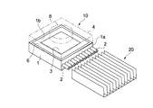
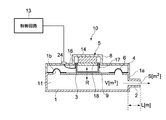
図1は、本発明の一実施の形態に係る噴流発生装置とヒートシンクを示す斜視図である。図2は、図1に示す噴流発生装置10の断面図である。
FIG. 1 is a perspective view showing a jet flow generating device and a heat sink according to an embodiment of the present invention. FIG. 2 is a cross-sectional view of the jet
噴流発生装置10は、上部に矩形の穴1bが開けられた筐体1を備えている。筐体1の穴1bの周囲には、矩形の弾性支持部材6が装着され、この弾性支持部材6により振動体としての振動板3が支持されている。振動板3、弾性支持部材6及び筐体1によりチャンバ11が形成される。筐体1の側面1aには、チャンバ11内の空気を筐体1の外部に配置されたヒートシンク20に向けて吐出するための複数のノズル2が取り付けられている。ノズル2は、筐体1と一体的に形成されていてもよい。
The
筐体1の上部には、振動板3を駆動するためのアクチュエータ5が配置されている。例えば円筒状のヨーク8の内側に、振動板3aの振動方向Rに着磁されたマグネット14が内蔵され、マグネット14には、例えば円板状のヨーク18が取り付けられている。このマグネット14、ヨーク8及び18により磁気回路が構成される。マグネット14とヨーク8との間の空間には、コイル17が巻回されたコイルボビン9が出入りするようになっている。すなわち、アクチュエータ5はボイスコイルモータでなる。アクチュエータ5には、給電線16が接続されている。給電線16はカバー4に取り付けられた端子24を介して例えば駆動用のIC等の制御回路13に電気的に接続されている。この制御回路13からアクチュエータ5に電気信号が供給される。
An
ヨーク8は、筐体1の上部を覆うカバー4と一体的に形成されている。しかし、マグネット14により発生する磁束がヨーク8からカバー4へ拡散することを防ぐ観点から、ヨーク8とカバー4とを異なる材料とすることも可能である。コイルボビン9は振動板3の表面に固定されている。このようなアクチュエータ5により、振動板3を矢印Rの方向に振動させることができる。
The yoke 8 is formed integrally with the cover 4 that covers the upper portion of the housing 1. However, from the viewpoint of preventing the magnetic flux generated by the
筐体1は、例えば、樹脂、ゴム、金属、またはセラミックスでなる。樹脂やゴムは成形で作製しやすく量産向きである。また、樹脂やゴムの場合、音の減衰率も高くなり、騒音を抑制することができる。さらに、軽量化に対応できるし、低コストとなる。金属としては、筐体1の放熱を考慮すると、熱伝導性のよい銅やアルミがよい。カバー4の材料も、例えば、樹脂、ゴム、金属、またはセラミックス等でなる。筐体1及びカバー4の材料はそれぞれ同じものであってもよいし、別の材料であってもよい。弾性支持部材6は、例えば樹脂、ゴム等でなる。
The housing 1 is made of, for example, resin, rubber, metal, or ceramics. Resin and rubber are easy to produce by molding and are suitable for mass production. Moreover, in the case of resin or rubber, the sound attenuation rate is also increased, and noise can be suppressed. Furthermore, it can cope with weight reduction and is low in cost. As the metal, considering heat dissipation of the housing 1, copper or aluminum having good thermal conductivity is preferable. The material of the cover 4 is also made of, for example, resin, rubber, metal, ceramics, or the like. The material of the housing 1 and the cover 4 may be the same or different materials. The
振動板3は、例えば、樹脂、紙、ゴム、または金属等でなる。振動板3の形状は、図示するような平板状に限らず、スピーカに搭載される振動板のようなコーン状であってもよい。あるいは立体的な形状であってもよい。
The
以上のように構成された噴流発生装置10の動作について説明する。
The operation of the jet
アクチュエータ5に例えば正弦波の交流電圧が印加されると、振動板3は正弦波振動を行う。これにより、チャンバ11内の容積が増減する。チャンバ11の容積変化に伴い、チャンバ11の圧力が変化することでノズル2から空気の流れが脈流として発生する。例えば、振動板3がチャンバ11の容積を増加させる方向に変位すると、チャンバ11の圧力は減少する。これによりノズル2を介して筐体1の外部の空気がチャンバ11内に流れ込む。逆に、振動板3がチャンバ11の容積を減少させる方向に変位すると、チャンバ11の圧力は増加する。これにより、チャンバ11内にある空気がノズル2を介して外部に噴出され、ヒートシンク20にその空気が吹き付けられる。ノズル2から空気が噴出されるときにノズル2の周囲の気圧が低下することにより、当該周囲の空気がノズル2から吐出される空気に巻き込まれる。すなわち、これが合成噴流である。このような合成噴流が、ヒートシンク20に吹き付けられることにより、ヒートシンク20を冷却することができる。
For example, when a sinusoidal AC voltage is applied to the
ここで、本実施の形態に係る筐体1が、振動板3が振動することに起因して発生する音のうち最大の騒音レベルを有する音が所定の周波数になるように構成されている。したがって、例えば、適宜その周波数を設定すれば、空気の吐出量を低下させることなく騒音の発生を抑制することができる。
Here, the housing 1 according to the present embodiment is configured such that the sound having the maximum noise level among the sounds generated due to the vibration of the
振動板3が振動することに起因して発生する音とは、振動板3の往復運動によってチャンバ11内の気圧が周期的に変動することで発生する音波である(以下、第1の音という。)。第1の音は、主に、例えばチャンバ11内の気圧が周期的に変動することにより、筐体1やカバー4等にその振動が伝達され、これにより発生する音である。振動板3が振動することに起因して発生する音のうちもう1つは、振動板3の往復運動によって発生する気体の流れの乱れによる気流音である(以下、第2の音という。)。第2の音は、主に、ノズル2から空気が吐出されるときに発生する気流音である。
The sound generated due to the vibration of the
このように本実施の形態では、これら第1の音及び第2の音のうち最大の騒音レベルを有する音が所定の周波数になるように、筐体1が形成されている。ここで、騒音レベルとは、音圧レベルを人間の聴感特性に合わせるように補正したレベルをいう。 As described above, in the present embodiment, the housing 1 is formed such that the sound having the maximum noise level among the first sound and the second sound has a predetermined frequency. Here, the noise level refers to a level corrected so that the sound pressure level matches the human auditory characteristics.
図3は人間の聴感特性を示したグラフである。このグラフは、JIS規格で規定された等ラウドネス曲線(A特性のもの)であり、20[Hz]〜20[kHz]の周波数帯域において、人が同じ音圧レベルに晒されたときに、どれほどの大きさに聞こえるかを表したものである。すなわち、1[kHz]の音波を基準として、各周波数の音がどれだけの大きさで聴こえるかを表したものである。この図より、同じ音圧レベルでも、1[kHz]の音に比べ50[Hz]の音は30[dB]小さく聴こえる、つまり「騒音レベル」が小さくなるということがわかる。音圧レベルLp[dB]は以下の式(1)で定義される。
Lp=20log(p/p0)・・・式(1)
(pは音圧[Pa]、p0は基準音圧[20μPa]である。)
FIG. 3 is a graph showing human auditory characteristics. This graph is an equal loudness curve (A characteristic) defined in the JIS standard, and how much is it when a person is exposed to the same sound pressure level in a frequency band of 20 [Hz] to 20 [kHz]? It shows what sounds like. That is, it represents how loud the sound of each frequency can be heard with a sound wave of 1 [kHz] as a reference. From this figure, it can be seen that even at the same sound pressure level, the sound of 50 [Hz] can be heard 30 [dB] smaller than the sound of 1 [kHz], that is, the “noise level” is reduced. The sound pressure level Lp [dB] is defined by the following equation (1).
Lp = 20 log (p / p0) (1)
(P is the sound pressure [Pa], and p0 is the reference sound pressure [20 μPa].)
このような事実を考慮して、例えば、当該最大騒音レベルを有する音の周波数が1Hz以上であって1[kHz]未満とすればよい。1[kHz]〜6[kHz]の周波数は、人間にとって比較的騒音が大きく感じられるからである。したがって、1[kHz]未満とすれば、騒音が感じにくくなる。1[Hz]より小さいと、単位時間当りの期待する最低の気体吐出量が得られない。 In consideration of such a fact, for example, the frequency of the sound having the maximum noise level may be 1 Hz or more and less than 1 [kHz]. This is because a frequency of 1 [kHz] to 6 [kHz] feels relatively loud for humans. Therefore, if it is less than 1 [kHz], it becomes difficult to feel noise. If it is less than 1 [Hz], the expected minimum gas discharge rate per unit time cannot be obtained.
あるいは1[Hz]以上500[Hz]未満、または1[Hz]以上20[Hz]未満であってもよい。500[Hz]未満であれば、図3のグラフから1[kHz]のときより3[dB]以上音圧レベルが下がり、かなり騒音が抑制されるからである。20[Hz]未満は人間の可聴範囲外だからである。 Alternatively, it may be 1 [Hz] or more and less than 500 [Hz], or 1 [Hz] or more and less than 20 [Hz]. This is because if it is less than 500 [Hz], the sound pressure level is lowered by 3 [dB] or more from the graph of FIG. This is because less than 20 [Hz] is outside the human audible range.
また、上記のように1[kHz]〜6[kHz]の周波数は、人間にとって比較的騒音が大きく感じられるので、6[kHz]以上であって40[kHz]未満であればよい。40kHz以上の場合、振幅が小さすぎるため実用的でない。 Further, as described above, the frequency of 1 [kHz] to 6 [kHz] may be relatively higher than 6 [kHz] and less than 40 [kHz] because humans feel relatively loud noise. When the frequency is 40 kHz or more, the amplitude is too small to be practical.
あるいは、10[kHz]以上40[kHz]未満、または20[kHz]以上40[kHz]未満であってもよい。10[kHz]以上であれば、1[kHz]のときより3[dB]以上音圧レベルが下がり、かなり騒音が抑制されるからである。20[kHz]以上は人間の可聴範囲外だからである。 Alternatively, it may be 10 [kHz] or more and less than 40 [kHz], or 20 [kHz] or more and less than 40 [kHz]. This is because if it is 10 [kHz] or more, the sound pressure level is lowered by 3 [dB] or more from 1 [kHz], and noise is considerably suppressed. This is because 20 [kHz] or more is outside the human audible range.
具体的には、筐体1は、最大の騒音レベルを有する音が上記のような周波数となるように、図2に示すようにノズル2の長さ(開口の長さ)L[m]、その開口面積(ノズル2の流路断面積であり、具体的には、ノズル2の上記長さの方向にほぼ垂直な面の面積である。)S[m2]、及びチャンバ11の容積V[m3]のうち少なくとも1つが設定されている。この場合、音速がC[m/s]、上記開口の開口面の半径がr[m]、開口の数(ノズル2の数)がnである場合、下の式(2)〜(7)を満たすとよい。
Specifically, the housing 1 has a length (opening length) L [m] of the
{C/(2π)}・[πr2/{V/(1.2r・n1/2 + L)}] 1/2 < 1000・・・式(2)
{C/(2π)}・[πr2/{V/(1.2r・n1/2 + L)}] 1/2 < 500・・・式(3)
{C/(2π)}・[πr2/{V/(1.2r・n1/2 + L)}] 1/2 < 20・・・式(4)
{C/(2π)}・[πr2/{V/(1.2r・n1/2 + L)}] 1/2 ≧ 6000・・・式(5)
{C/(2π)}・[πr2/{V/(1.2r・n1/2 + L)}] 1/2 ≧ 10000・・・式(6)
{C/(2π)}・[πr2/{V/(1.2r・n1/2 + L)}] 1/2 ≧ 20000・・・式(7)
{C / (2π)} · [πr 2 /{V/(1.2r·n 1/2 + L)}] 1/2 <1000 (2)
{C / (2π)} · [πr 2 /{V/(1.2r·n 1/2 + L)}] 1/2 <500 Formula (3)
{C / (2π)} · [πr 2 /{V/(1.2r·n 1/2 + L)}] 1/2 <20 Equation (4)
{C / (2π)} · [πr 2 /{V/(1.2r·n 1/2 + L)}] 1/2 ≧ 6000 (5)
{C / (2π)} · [πr 2 /{V/(1.2r·n 1/2 + L)}] 1/2 ≧ 10000 (6)
{C / (2π)} · [πr 2 /{V/(1.2r·n 1/2 + L)}] 1/2 ≧ 20000 (7)
つまり、ヘルムホルツの共鳴周波数を所定の周波数未満、または所定の周波数以上となるように、筐体が構成されるとよい。これらの式(2)〜(7)の右辺の数の意義は、上記の理由と同様である。 In other words, the housing is preferably configured such that the Helmholtz resonance frequency is less than a predetermined frequency or higher than a predetermined frequency. The significance of the number of the right side of these formulas (2) to (7) is the same as the above reason.
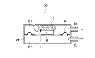
図4は、本発明の他の実施の形態に係る噴流発生装置を示す断面図である。これ以降の説明では、上記の実施の形態に係る噴流発生装置10の部材や機能等について同様のものは説明を簡略または省略し、異なる点を中心に説明する。
FIG. 4 is a cross-sectional view showing a jet flow generating apparatus according to another embodiment of the present invention. In the following description, the description of the same members and functions of the jet
この噴流発生装置30の筐体21の内部は、振動板3及び弾性支持部材6により仕切られて第1のチャンバ11a及び第2のチャンバ11bが形成されている。筐体21には、第1及び第2のチャンバ11a及び11bにそれぞれ連通する開口を形成するノズル2a及び2bが設けられている。このような噴流発生装置30では、アクチュエータ5に例えば正弦波の交流電圧が印加されることで、振動板3が振動する。振動板3が振動することにより、各チャンバ11a及び11b内の圧力が交互に増減し、ノズル2a及び2bを介して交互に空気が出入りする。つまり、第1のチャンバ11aからノズル2aを介して筐体21外部へ空気が吐出されるときは、外部からノズル2bを介して第2のチャンバ11bへ空気が流入する。逆に、第2のチャンバ11bからノズル2bを介して筐体21外部へ空気が吐出されるときは、外部からノズル2aを介して第1のチャンバ11aへ空気が流入する。
The interior of the
この実施の形態に係る噴流発生装置30についても、上記同様、最大騒音レベルを有する音の周波数が所定の周波数になるように構成される。これにより、騒音が抑制され静音化が図れる。この場合、第1のチャンバ11a及び第2のチャンバ11bのうち少なくとも一方から発生する第1の音または第2の音の周波数が、上記した、1Hz以上であって1[kHz]未満等の周波数範囲に入っていることが望ましい。あるいは、第1のチャンバ11a及び第2のチャンバ11bのうち少なくとも一方について、上記式(2)〜(7)のうちいずれか1つを満たすことが望ましい。
The
一方、ノズル2a及び2bから空気が噴出されるときに、例えば各ノズル2a及びノズル2bから独立して音が発生する。この音は上記第1の音に種別される。しかしながら、各ノズル2a及びノズル2bとで発生する各音波は逆位相の音波であるため互いに弱められる。これにより、騒音が抑制され、さらなる静音化を図ることができる。
On the other hand, when air is ejected from the
また、第1及び第2のチャンバ11a及び11bの容積は同じであることが好ましい。これにより、吐出される空気量も同じになり静音化が向上する。
The volumes of the first and
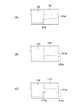
図5は、別の実施の形態に係る噴流発生装置の筐体を示す図である。図5(A)及び図5(B)について、それぞれ左図が正面図、右図が側面図である。図5(A)に示す筐体1に設けられた複数のノズル22は、その開口の形状が矩形である。図5(B)に示す筐体1に設けられた複数のノズル32は、その開口の形状が楕円形である。これらのような形状のノズルの場合、上記開口面積を考慮するときは、例えば矩形ならその矩形の面積と等しい面積を有する円の半径rを考える。
FIG. 5 is a diagram illustrating a housing of a jet flow generating device according to another embodiment. 5A and 5B, the left figure is a front view and the right figure is a side view, respectively. The plurality of
図6は、さらに別の実施の形態に係る噴流発生装置の筐体を示す図である。図6(A)に示す筐体31には、管状の開口31aが複数設けられている。この開口31aがノズルの機能を果たす。すなわち、ノズル状のものではなく、単に筐体31に管状の孔が開けられるだけでもよい。
FIG. 6 is a diagram illustrating a housing of a jet flow generating device according to still another embodiment. A plurality of
図6(B)は、図4で示したようなチャンバが2つある筐体を示す。この筐体41の2つのチャンバにそれぞれ開口41a及び42bが連通している。
FIG. 6B shows a housing having two chambers as shown in FIG.
図6(C)に示す筐体51は、その開口51aを形成するノズル部分に斜面51bが設けられている。つまり、チャンバの外部に向かってそのノズルの図中縦幅が狭くなるような斜面51bが設けられている。このような構成により、開口51aから気体が吐出されるときにノズル周囲の気体の巻き込みやすくなる。すなわち合成噴流の気体量を増加させることができる。図中、縦幅が狭くなるような斜面ではなく、あるいはこの斜面51bに加え、図中横幅(紙面に垂直方向)のノズルの幅が狭くなるような別の斜面があってもよい。
The
図6(D)は、図6(B)同様の2つのチャンバに連通する開口61a及び61bがあり、かつ、図6(C)同様の斜面61cがある形態を示している。
FIG. 6D shows a form in which there are
図7は、さらに別の実施の形態に係る噴流発生装置の筐体の一部を示す側面図である。この筐体71には、例えば開口71a及び開口71bがそれぞれ複数設けられている。筐体71は、例えば図6(B)で示したように2つのチャンバを内部に有し、これら各チャンバに開口71a及び71bがそれぞれ連通している。
FIG. 7 is a side view showing a part of a casing of a jet flow generating device according to still another embodiment. The
今、各開口71a及び71bの開口面積がほぼ同じであって、その等価円半径をrとする。この場合、図7に示すように、開口71a及び71b間の距離d1(開口71a及び71bの中心間の距離)は、rの3倍以上に設定されている。つまり図中、d2がrの1倍以上に設定されている。例えば、開口71aから空気が外部へ吐出されるときは、開口71bから空気が筐体1内へ空気が流入される。したがって、開口71aと71bの位置が近すぎる場合、開口71aから吐出された空気が開口71bから流入してしまい、図示しない発熱体に吹き付けられる空気の量が減少するおそれがある。しかし、本実施の形態のように3r≦d1とすることにより、そのような問題を解消できる。
Now, the opening areas of the
一方、各開口71a及び71bから発生する例えば第2の音の波長がλ[m]の場合、d1<λ/2とすることが望ましい。各開口71a及び71bの開口面の中心がそれぞれの音源とすると、d1<λ/2の場合、各開口71a及び71bから発生した音波のほぼ最大振幅同士で強め合う箇所がなくなるので、騒音の発生を防止することができる。なお、媒体が空気の場合に音速が340[m/s]前後の場合、人間の可聴範囲の音の波長は1.7[mm]〜17[m]程度である。
On the other hand, for example, when the wavelength of the second sound generated from each of the
図8は、図7に示した筐体71の変形例を示す斜視図である。筐体81に形成された開口81a及び81bの間に仕切り板81cが取り付けられている。この仕切り板81cは、筐体81と同じ材料で一体的に形成されていてもよい。このような構成により、上記同様に、互いの開口81a及び81bの間で空気が出入りしてしまうことを防止できる。この場合、開口81a及び81b間の距離は、図7で示したように必ずしも1倍以上とする必要はなく、1倍より狭くてもよい。
FIG. 8 is a perspective view showing a modified example of the
図9は、さらに別の実施の形態に係る噴流発生装置の筐体の一部を示す側面図である。図9(A)に示すように、筐体91内のチャンバ92から空気を吐出するための開口91aが、そのチャンバ92側の端部91bで、当該チャンバ92に向かって開口面積が広がるように形成されている。これにより、チャンバ92から空気が流出入するときの気流がスムーズになり、第2の音の騒音レベルが低減される。
FIG. 9 is a side view showing a part of a casing of a jet flow generating device according to still another embodiment. As shown in FIG. 9A, the
図9(B)に示す筐体101の開口101aでは、チャンバ102とは逆側の端部、つまり外部側の端部101bが、その外部側に向けて開口面積が広がるように形成されている。このような構成によっても気流をスムーズにし、第2の音の騒音レベルが低減される。
In the
また、図9(C)に示す筐体111の開口111aは両端部111b及び111cが広がるように形成されている。これにより、さらに気流がスムーズになる。
Further, the
本発明は以上説明した実施の形態には限定されるものではなく、種々の変形が可能である。 The present invention is not limited to the embodiment described above, and various modifications are possible.
例えば、図1で示した筐体1は直方体形状であるが、その他、円筒形状や三角柱形状でもよい。筐体1の形状がそのような円筒形状、つまりその平面形状が例えば円である場合、振動板3も円板形状であることが望ましい。つまり両者が相似形であることが望ましい。
For example, the housing 1 shown in FIG. 1 has a rectangular parallelepiped shape, but may be a cylindrical shape or a triangular prism shape. When the shape of the housing 1 is such a cylindrical shape, that is, when the planar shape is, for example, a circle, it is desirable that the
また、図1で示した平板状のヨーク18の平面形状は、例えば円形である。しかし、円でなくても楕円や、矩形状でもよい。一方、振動板3aの形状も図示では矩形であるが、アクチュエータ5の平面形状と相似な円形であってもよい。
Further, the planar shape of the
図9(A)〜(C)において、端部91b、101b、111b及び111cは図ではそれぞれ曲面としたが、平面な斜面であるテーパ状であってもよい。
In FIGS. 9A to 9C, the
上記各実施の形態のうち少なくとも2つを組み合わせることも可能である。例えば図6(B)で示した2つのチャンバの開口41a及び41bの端部を、図9(A)〜(C)のうちいずれか1つの形態で構成することができる。あるいは、図6(C)または図6(D)で示した筐体51または61の開口51a等を、図9(A)〜(C)のうちいずれか1つの形態で構成することができる。またあるいは、図4で示した筐体1のノズル2aと2bとの開口間の距離が図7で示したようにd1としてもよい。
It is also possible to combine at least two of the above embodiments. For example, the ends of the
1、21、31、41、51、61、71、81、91、101、111…筐体
2、2a、2b、12a、12b、22…ノズル
3…振動板
10、30…噴流発生装置
11、92、102、112…チャンバ
11a…第1のチャンバ
11b…第2のチャンバ
20…ヒートシンク
31a、41a、41b、51a、61a、61b、71a、71b、81a、81b、91a、101a、111a…開口
91b、101b、111b、111c…端部
91b.101b…端部
92…チャンバ
1, 2, 31, 41, 51, 61, 71, 81, 91, 101, 111 ... casing 2, 2a, 2b, 12a, 12b, 22 ...
Claims (2)
前記振動体を駆動する駆動部と、
第1及び第2の開口部と、前記第1の開口部に連通し前記気体を含む第1のチャンバと、前記第2の開口部に連通し前記振動体に対して前記第1のチャンバの反対側に設けられ前記気体を含む第2のチャンバとを有し、前記振動体を支持し、前記振動体が振動することに起因して発生する音のうち最大の騒音レベルを有する音が、6[kHz]以上40[kHz]未満、10[kHz]以上40[kHz]未満、または、20[kHz]以上40[kHz]未満を満たす周波数になるように構成され、前記振動体の駆動により前記第1及び第2の開口部を介して交互に前記気体を脈流として吐出させる筐体と
を具備し、
前記筐体は、前記第1及び第2の開口部の各開口面積の等価円半径がほぼ同じr[m]、前記第1及び第2の開口部間の距離がd[m]、前記最大の騒音レベルを有する音の波長がλ[m]の場合、
3r≦d<λ/2
を満たし、
前記第1の開口部は、前記第1のチャンバ側に設けられ、前記第1のチャンバ側に向かって前記第1の開口部の開口面積が広がるように形成された第1の端部と、前記筐体の外部側に設けられ、当該外部側に向かって前記第1の開口部の開口面積が広がるように形成された第2の端部とを有し、
前記第2の開口部は、前記第2のチャンバ側に設けられ、前記第2のチャンバ側に向かって前記第2の開口部の開口面積が広がるように形成された第3の端部と、前記筐体の外部側に設けられ、当該外部側に向かって前記第2の開口部の開口面積が広がるように形成された第4の端部とを有する
ことを特徴とする噴流発生装置。 A vibrating body that vibrates the gas;
A drive unit for driving the vibrating body;
First and second openings, a first chamber that communicates with the first opening and contains the gas, and communicates with the second opening and includes And a second chamber containing the gas provided on the opposite side, supporting the vibrating body, and having a maximum noise level among sounds generated due to vibration of the vibrating body , It is configured to have a frequency satisfying 6 [kHz] or more and less than 40 [kHz], 10 [kHz] or more and less than 40 [kHz], or 20 [kHz] or more and less than 40 [kHz]. A housing that alternately discharges the gas as a pulsating flow through the first and second openings ,
In the case, the equivalent circular radius of each opening area of the first and second openings is substantially the same r [m], the distance between the first and second openings is d [m], and the maximum If the wavelength of the sound with the noise level is λ [m],
3r ≦ d <λ / 2
The filling,
The first opening is provided on the first chamber side, and a first end formed so that an opening area of the first opening widens toward the first chamber side; A second end portion provided on the outer side of the housing and formed so that an opening area of the first opening portion increases toward the outer side;
The second opening is provided on the second chamber side, and a third end formed so that an opening area of the second opening widens toward the second chamber side; A jet flow generating device , comprising: a fourth end portion provided on an outer side of the casing and formed so that an opening area of the second opening portion increases toward the outer side .
気体に振動を与える振動体と、
前記振動体を駆動する駆動部と、
第1及び第2の開口部と、前記第1の開口部に連通し前記気体を含む第1のチャンバと、前記第2の開口部に連通し前記振動体に対して前記第1のチャンバの反対側に設けられ前記気体を含む第2のチャンバとを有し、前記振動体を支持し、前記振動体が振動することに起因して発生する音のうち最大の騒音レベルを有する音が、6[kHz]以上40[kHz]未満、10[kHz]以上40[kHz]未満、または、20[kHz]以上40[kHz]未満を満たす周波数になるように構成され、前記振動体の駆動により前記第1及び第2の開口部を介して交互に前記気体を脈流として前記発熱体に向けて吐出させる筐体と
を具備し、
前記筐体は、前記第1及び第2の開口部の各開口面積の等価円半径がほぼ同じr[m]、前記第1及び第2の開口部間の距離がd[m]、前記最大の騒音レベルを有する音の波長がλ[m]の場合、
3r≦d<λ/2
を満たし、
前記第1の開口部は、前記第1のチャンバ側に設けられ、前記第1のチャンバ側に向かって前記第1の開口部の開口面積が広がるように形成された第1の端部と、前記筐体の外部側に設けられ、当該外部側に向かって前記第1の開口部の開口面積が広がるように形成された第2の端部とを有し、
前記第2の開口部は、前記第2のチャンバ側に設けられ、前記第2のチャンバ側に向かって前記第2の開口部の開口面積が広がるように形成された第3の端部と、前記筐体の外部側に設けられ、当該外部側に向かって前記第2の開口部の開口面積が広がるように形成された第4の端部とを有する
ことを特徴とする電子機器。 A heating element;
A vibrating body that vibrates the gas;
A drive unit for driving the vibrating body;
First and second openings, a first chamber that communicates with the first opening and contains the gas, and communicates with the second opening and includes And a second chamber containing the gas provided on the opposite side, supporting the vibrating body, and having a maximum noise level among sounds generated due to vibration of the vibrating body , It is configured to have a frequency satisfying 6 [kHz] or more and less than 40 [kHz], 10 [kHz] or more and less than 40 [kHz], or 20 [kHz] or more and less than 40 [kHz]. A housing for alternately discharging the gas as a pulsating flow toward the heating element through the first and second openings ,
In the case, the equivalent circular radius of each opening area of the first and second openings is substantially the same r [m], the distance between the first and second openings is d [m], and the maximum If the wavelength of the sound with the noise level is λ [m],
3r ≦ d <λ / 2
The filling,
The first opening is provided on the first chamber side, and a first end formed so that an opening area of the first opening widens toward the first chamber side; A second end portion provided on the outer side of the housing and formed so that an opening area of the first opening portion increases toward the outer side;
The second opening is provided on the second chamber side, and a third end formed so that an opening area of the second opening widens toward the second chamber side; An electronic apparatus comprising: a fourth end portion provided on an outer side of the housing and formed so that an opening area of the second opening portion increases toward the outer side .
Priority Applications (6)
| Application Number | Priority Date | Filing Date | Title |
|---|---|---|---|
| JP2005123432A JP4747657B2 (en) | 2005-04-21 | 2005-04-21 | Jet generator and electronic device |
| EP06006562A EP1715566A2 (en) | 2005-04-21 | 2006-03-29 | Jet generating device including a vibrating member |
| TW095111119A TW200710638A (en) | 2005-04-21 | 2006-03-30 | Jet current generation apparatus and electronic appliance |
| KR1020060035169A KR101295488B1 (en) | 2005-04-21 | 2006-04-19 | Jet generating device and electronic apparatus |
| US11/379,508 US7793709B2 (en) | 2005-04-21 | 2006-04-20 | Jet generating device and electronic apparatus |
| CNB2006100746582A CN100442487C (en) | 2005-04-21 | 2006-04-21 | Jet generating device and electronic apparatus |
Applications Claiming Priority (1)
| Application Number | Priority Date | Filing Date | Title |
|---|---|---|---|
| JP2005123432A JP4747657B2 (en) | 2005-04-21 | 2005-04-21 | Jet generator and electronic device |
Publications (2)
| Publication Number | Publication Date |
|---|---|
| JP2006297295A JP2006297295A (en) | 2006-11-02 |
| JP4747657B2 true JP4747657B2 (en) | 2011-08-17 |
Family
ID=36721525
Family Applications (1)
| Application Number | Title | Priority Date | Filing Date |
|---|---|---|---|
| JP2005123432A Expired - Fee Related JP4747657B2 (en) | 2005-04-21 | 2005-04-21 | Jet generator and electronic device |
Country Status (6)
| Country | Link |
|---|---|
| US (1) | US7793709B2 (en) |
| EP (1) | EP1715566A2 (en) |
| JP (1) | JP4747657B2 (en) |
| KR (1) | KR101295488B1 (en) |
| CN (1) | CN100442487C (en) |
| TW (1) | TW200710638A (en) |
Families Citing this family (29)
| Publication number | Priority date | Publication date | Assignee | Title |
|---|---|---|---|---|
| US20060196638A1 (en) * | 2004-07-07 | 2006-09-07 | Georgia Tech Research Corporation | System and method for thermal management using distributed synthetic jet actuators |
| JP2006310586A (en) | 2005-04-28 | 2006-11-09 | Sony Corp | Air current generator and electronic apparatus |
| JP2010511142A (en) * | 2006-11-30 | 2010-04-08 | コーニンクレッカ フィリップス エレクトロニクス エヌ ヴィ | Pulsating cooling system |
| US20080137289A1 (en) * | 2006-12-08 | 2008-06-12 | General Electric Company | Thermal management system for embedded environment and method for making same |
| EP1975505A1 (en) * | 2007-03-26 | 2008-10-01 | Koninklijke Philips Electronics N.V. | Lighting device |
| JP2008280917A (en) * | 2007-05-10 | 2008-11-20 | Alps Electric Co Ltd | Piezoelectric gas injection device |
| US20090084866A1 (en) * | 2007-10-01 | 2009-04-02 | Nuventix Inc. | Vibration balanced synthetic jet ejector |
| JP5643651B2 (en) * | 2007-12-07 | 2014-12-17 | コーニンクレッカ フィリップス エヌ ヴェ | Low noise cooling device |
| JP5205957B2 (en) | 2007-12-27 | 2013-06-05 | ソニー株式会社 | Piezoelectric pump, cooling device and electronic device |
| JP4591521B2 (en) | 2008-02-18 | 2010-12-01 | ソニー株式会社 | Electronic device having a piezoelectric pump |
| EP2101351B1 (en) | 2008-03-13 | 2016-08-17 | Siemens Aktiengesellschaft | Cooling device for cooling a component |
| CN102187457A (en) * | 2008-10-17 | 2011-09-14 | 皇家飞利浦电子股份有限公司 | Cooling arrangement |
| KR101060758B1 (en) | 2008-11-19 | 2011-08-31 | 삼성엘이디 주식회사 | Cooling device of light emitting device package of vibration generating device and head lamp of vibration generating device |
| CN102388626B (en) | 2009-04-10 | 2015-02-25 | 皇家飞利浦电子股份有限公司 | Audio driver |
| EP2282335A1 (en) * | 2009-08-05 | 2011-02-09 | Siemens Aktiengesellschaft | Cooling device and method |
| CN102245005B (en) * | 2010-05-14 | 2015-03-25 | 富瑞精密组件(昆山)有限公司 | Heat radiating device and airflow generator thereof |
| US20120285667A1 (en) * | 2011-05-13 | 2012-11-15 | Lighting Science Group Corporation | Sound baffling cooling system for led thermal management and associated methods |
| CN102358419A (en) * | 2011-07-22 | 2012-02-22 | 北京航空航天大学 | Efficient pulse jet flow generating method based on square wave and apparatus thereof |
| TWI524840B (en) | 2012-03-30 | 2016-03-01 | 台達電子工業股份有限公司 | Heat dissipating module |
| TWI475180B (en) | 2012-05-31 | 2015-03-01 | Ind Tech Res Inst | Synthetic jet equipment |
| JP2014107362A (en) * | 2012-11-27 | 2014-06-09 | Lenovo Singapore Pte Ltd | Heat dissipation device of electronic device and heat dissipation method |
| CN103857257B (en) * | 2012-11-28 | 2017-04-19 | 联想(北京)有限公司 | Electronic device and electronic device cooling method |
| KR20150128939A (en) * | 2013-03-14 | 2015-11-18 | 제네럴 일렉트릭 컴퍼니 | Low resonance acoustic synthetic jet structure |
| CN104219931B (en) * | 2013-05-31 | 2017-04-05 | 英业达科技有限公司 | Radiating module |
| JP6260178B2 (en) * | 2013-10-01 | 2018-01-17 | オムロン株式会社 | Enclosure and electrical equipment |
| TWI539267B (en) * | 2013-12-24 | 2016-06-21 | 台達電子工業股份有限公司 | Heat dissipating apparatus and electronic device |
| WO2015133283A1 (en) | 2014-03-07 | 2015-09-11 | 株式会社村田製作所 | Blower |
| CN111204226B (en) * | 2018-02-10 | 2021-04-02 | 重庆桴之科科技发展有限公司 | Sensor device for electric vehicle |
| CN117299516B (en) * | 2023-11-30 | 2024-04-02 | 珠海格力电器股份有限公司 | Air conditioner and control method thereof |
Family Cites Families (20)
| Publication number | Priority date | Publication date | Assignee | Title |
|---|---|---|---|---|
| JPS58140491A (en) * | 1982-02-16 | 1983-08-20 | Matsushita Electric Ind Co Ltd | Flow generating device |
| JPH02213200A (en) * | 1989-02-14 | 1990-08-24 | Victor Co Of Japan Ltd | Heat exchanger |
| JPH03116961A (en) * | 1989-09-29 | 1991-05-17 | Victor Co Of Japan Ltd | Heat dissipating device |
| JPH03168373A (en) * | 1989-11-24 | 1991-07-22 | Nippon Keiki Seisakusho:Kk | Piezoelectric pump control device |
| JPH03222878A (en) * | 1990-01-26 | 1991-10-01 | Mitsubishi Kasei Corp | Piezoelectric vibrator pump |
| JP3006361B2 (en) * | 1992-09-30 | 2000-02-07 | 株式会社日立製作所 | Heat sink, electronic device using the same, and electronic computer using the electronic device |
| EP0732513B1 (en) * | 1995-03-14 | 2003-02-05 | Sulzer Markets and Technology AG | Method and device for active damping of oscillations in detached unstable flows |
| US5758823A (en) * | 1995-06-12 | 1998-06-02 | Georgia Tech Research Corporation | Synthetic jet actuator and applications thereof |
| US6123145A (en) | 1995-06-12 | 2000-09-26 | Georgia Tech Research Corporation | Synthetic jet actuators for cooling heated bodies and environments |
| JPH09126128A (en) * | 1995-10-27 | 1997-05-13 | Matsushita Electric Works Ltd | Enclosure of pump |
| SE514735C2 (en) * | 1998-12-11 | 2001-04-09 | Ericsson Telefon Ab L M | Device for increasing heat output |
| KR20000050679A (en) * | 1999-01-13 | 2000-08-05 | 윤종용 | Heat sinking apparatus for electronic equipment |
| US6353295B1 (en) * | 1999-01-20 | 2002-03-05 | Philips Electronics North America Corporation | Lamp electronic ballast with a piezoelectric cooling fan |
| JP2000252669A (en) * | 1999-02-26 | 2000-09-14 | Sony Corp | Cooling arrangement and electronic equipment |
| JP2002339900A (en) * | 2001-05-11 | 2002-11-27 | Sony Corp | Piezoelectric fan |
| JP3576524B2 (en) * | 2001-11-09 | 2004-10-13 | 松下電器産業株式会社 | Vibration generator and portable device using the same |
| US6588497B1 (en) | 2002-04-19 | 2003-07-08 | Georgia Tech Research Corporation | System and method for thermal management by synthetic jet ejector channel cooling techniques |
| JP4380250B2 (en) * | 2002-08-28 | 2009-12-09 | ソニー株式会社 | Heat transport device, electronic device and heat transport device manufacturing method |
| US6937472B2 (en) * | 2003-05-09 | 2005-08-30 | Intel Corporation | Apparatus for cooling heat generating components within a computer system enclosure |
| WO2005008348A2 (en) | 2003-07-07 | 2005-01-27 | Georgia Tech Research Corporation | System and method for thermal management using distributed synthetic jet actuators |
-
2005
- 2005-04-21 JP JP2005123432A patent/JP4747657B2/en not_active Expired - Fee Related
-
2006
- 2006-03-29 EP EP06006562A patent/EP1715566A2/en not_active Withdrawn
- 2006-03-30 TW TW095111119A patent/TW200710638A/en not_active IP Right Cessation
- 2006-04-19 KR KR1020060035169A patent/KR101295488B1/en not_active IP Right Cessation
- 2006-04-20 US US11/379,508 patent/US7793709B2/en not_active Expired - Fee Related
- 2006-04-21 CN CNB2006100746582A patent/CN100442487C/en not_active Expired - Fee Related
Also Published As
| Publication number | Publication date |
|---|---|
| US20060237171A1 (en) | 2006-10-26 |
| CN100442487C (en) | 2008-12-10 |
| CN1855457A (en) | 2006-11-01 |
| TW200710638A (en) | 2007-03-16 |
| KR20060110794A (en) | 2006-10-25 |
| US7793709B2 (en) | 2010-09-14 |
| EP1715566A2 (en) | 2006-10-25 |
| TWI336829B (en) | 2011-02-01 |
| KR101295488B1 (en) | 2013-08-09 |
| JP2006297295A (en) | 2006-11-02 |
Similar Documents
| Publication | Publication Date | Title |
|---|---|---|
| JP4747657B2 (en) | Jet generator and electronic device | |
| US7861767B2 (en) | Airflow generating device and electronic apparatus | |
| US8081454B2 (en) | Gas ejector, electronic device, and gas-ejecting method | |
| JP4677744B2 (en) | Jet generating device, electronic device and jet generating method | |
| JP5088526B2 (en) | Jet generator and electronic device | |
| CN100442200C (en) | Vibrating device for jet flow generating including a voice coil motor | |
| JP4867324B2 (en) | Heat dissipation device and electronic device | |
| JP2006310673A (en) | Jet flow generating device, heat sink, cooling device, and electronic apparatus | |
| JP4910464B2 (en) | Jet generator and electronic device | |
| JP2007142360A (en) | Radiator device and electronic apparatus | |
| JP4844236B2 (en) | NOZZLE, JET GENERATOR, COOLING DEVICE, AND ELECTRONIC DEVICE | |
| JP2007113530A (en) | Jet flow generator and electronic apparatus | |
| JP2006063900A (en) | Jet generating device and electronic apparatus | |
| JP2006336641A (en) | Jet generator and electronic device | |
| JP4900503B2 (en) | Gas ejection device and electronic device | |
| JP2007209845A (en) | Jet flow generator and electronic apparatus |
Legal Events
| Date | Code | Title | Description |
|---|---|---|---|
| A621 | Written request for application examination |
Free format text: JAPANESE INTERMEDIATE CODE: A621 Effective date: 20080311 |
|
| A977 | Report on retrieval |
Free format text: JAPANESE INTERMEDIATE CODE: A971007 Effective date: 20110127 |
|
| A131 | Notification of reasons for refusal |
Free format text: JAPANESE INTERMEDIATE CODE: A131 Effective date: 20110208 |
|
| A521 | Written amendment |
Free format text: JAPANESE INTERMEDIATE CODE: A523 Effective date: 20110404 |
|
| A01 | Written decision to grant a patent or to grant a registration (utility model) |
Free format text: JAPANESE INTERMEDIATE CODE: A01 Effective date: 20110419 |
|
| A61 | First payment of annual fees (during grant procedure) |
Free format text: JAPANESE INTERMEDIATE CODE: A61 Effective date: 20110502 |
|
| FPAY | Renewal fee payment (event date is renewal date of database) |
Free format text: PAYMENT UNTIL: 20140527 Year of fee payment: 3 |
|
| R250 | Receipt of annual fees |
Free format text: JAPANESE INTERMEDIATE CODE: R250 |
|
| LAPS | Cancellation because of no payment of annual fees |