JP2006310586A - Air current generator and electronic apparatus - Google Patents
Air current generator and electronic apparatus Download PDFInfo
- Publication number
- JP2006310586A JP2006310586A JP2005131875A JP2005131875A JP2006310586A JP 2006310586 A JP2006310586 A JP 2006310586A JP 2005131875 A JP2005131875 A JP 2005131875A JP 2005131875 A JP2005131875 A JP 2005131875A JP 2006310586 A JP2006310586 A JP 2006310586A
- Authority
- JP
- Japan
- Prior art keywords
- air
- chamber
- airflow
- opening
- generation device
- Prior art date
- Legal status (The legal status is an assumption and is not a legal conclusion. Google has not performed a legal analysis and makes no representation as to the accuracy of the status listed.)
- Pending
Links
Images


Classifications
-
- G—PHYSICS
- G06—COMPUTING; CALCULATING OR COUNTING
- G06F—ELECTRIC DIGITAL DATA PROCESSING
- G06F1/00—Details not covered by groups G06F3/00 - G06F13/00 and G06F21/00
- G06F1/16—Constructional details or arrangements
- G06F1/20—Cooling means
-
- H—ELECTRICITY
- H05—ELECTRIC TECHNIQUES NOT OTHERWISE PROVIDED FOR
- H05K—PRINTED CIRCUITS; CASINGS OR CONSTRUCTIONAL DETAILS OF ELECTRIC APPARATUS; MANUFACTURE OF ASSEMBLAGES OF ELECTRICAL COMPONENTS
- H05K7/00—Constructional details common to different types of electric apparatus
- H05K7/20—Modifications to facilitate cooling, ventilating, or heating
-
- H—ELECTRICITY
- H01—ELECTRIC ELEMENTS
- H01L—SEMICONDUCTOR DEVICES NOT COVERED BY CLASS H10
- H01L2924/00—Indexing scheme for arrangements or methods for connecting or disconnecting semiconductor or solid-state bodies as covered by H01L24/00
- H01L2924/0001—Technical content checked by a classifier
- H01L2924/0002—Not covered by any one of groups H01L24/00, H01L24/00 and H01L2224/00
Landscapes
- Engineering & Computer Science (AREA)
- Theoretical Computer Science (AREA)
- Physics & Mathematics (AREA)
- Human Computer Interaction (AREA)
- General Engineering & Computer Science (AREA)
- General Physics & Mathematics (AREA)
- Thermal Sciences (AREA)
- Microelectronics & Electronic Packaging (AREA)
- Cooling Or The Like Of Electrical Apparatus (AREA)
- Air-Conditioning For Vehicles (AREA)
- Jet Pumps And Other Pumps (AREA)
Abstract
Description
本発明は、気体の吐出させる気流発生装置及びこの気流発生装置を搭載した電子機器に関する。 The present invention relates to an airflow generation device that discharges gas and an electronic apparatus equipped with the airflow generation device.
従来から、PC(Personal Computer)の高性能化に伴うIC(Integrated Circuit)等の発熱体からの発熱量の増大が問題となっており、様々な放熱の技術が提案され、あるいは製品化されている。その放熱方法として、例えばICにアルミなどの金属でなる放熱用のフィンを接触させて、ICからの熱をフィンに伝導させて放熱する方法がある。また、ファンを用いることにより、例えばPCの筐体内の温まった空気を強制的に排除し、周囲の低温の空気を発熱体周辺に導入することで放熱する方法もある。あるいは放熱フィンとファンとを併用することにより、放熱フィンで発熱体と空気の接触面積を大きくしつつ、ファンにより放熱フィンの周囲の暖まった空気を強制的に排除する方法もある。 Conventionally, an increase in the amount of heat generated from a heating element such as an IC (Integrated Circuit) associated with high performance of a PC (Personal Computer) has been a problem, and various heat radiation technologies have been proposed or commercialized. Yes. As a heat dissipation method, for example, there is a method in which a heat dissipation fin made of a metal such as aluminum is brought into contact with the IC, and heat from the IC is conducted to the fin to dissipate heat. Also, there is a method of dissipating heat by forcibly removing, for example, warm air in a PC housing by using a fan and introducing ambient low-temperature air around the heating element. Alternatively, there is a method of forcibly removing the warm air around the radiating fin by the fan while using the radiating fin and the fan together to increase the contact area between the heating element and the air with the radiating fin.
しかしながら、このようなファンによる空気の強制対流では、放熱フィンの下流側でフィン表面の温度境界層が生起され、放熱フィンからの熱を効率的に奪えないという問題がある。このような問題を解決するためには、例えばファンの風速を上げて温度境界層を薄くすることが挙げられる。しかし、風速を上げるためにファンの回転数を増加させることにより、ファンの軸受け部分からの騒音や、ファンからの風が引き起こす風切り音などによる騒音が発生するという問題がある。 However, in such forced convection of air by the fan, there is a problem that a temperature boundary layer on the surface of the fin occurs on the downstream side of the radiating fin, and heat from the radiating fin cannot be efficiently taken. In order to solve such a problem, for example, the temperature of the temperature boundary layer can be reduced by increasing the wind speed of the fan. However, increasing the number of rotations of the fan in order to increase the wind speed has a problem in that noise from the bearing portion of the fan or noise due to wind noise caused by the wind from the fan occurs.
一方、送風手段としてファンを用いずに、上記温度境界層を破壊し、放熱フィンからの熱を効率よく外気に逃がす方法として、周期的に往復運動する振動板を用いる方法がある(例えば特許文献1、2、3、4参照)。これらの装置のうち、特に特許文献3及び4の装置は、チャンバ内を空間的に概略二分する振動板と、振動板を支持しチャンバに設けられた弾性体と、振動板を振動させる手段とを備えている。これらの装置では、例えば振動板が上方向に変位したときには、チャンバの上部空間の体積が減少するため、上部空間の圧力が上昇する。上部空間は吸排気口を通じて外気と連通しているため、上部空間の圧力上昇によって、その内部の空気の一部が外気中に放出される。一方このとき、振動板を挟んで上部空間と反対側にある下部空間の体積は逆に増加するため、下部空間の圧力が下降する。下部空間は吸排気口を通じて外気と連通しているため、下部空間の圧力減少によって、吸排気口近傍にある外気の一部が下部空間内部に引き込まれる。これとは逆に、振動板が下方向に変位したときには、チャンバの上部空間の体積が増加するため、上部空間の圧力が下降する。上部空間は吸排気口を通じて外気と連通しているため、上部空間の圧力下降によって、吸排気口近傍にある外気の一部が上部空間内部に引き込まれる。一方このとき、振動板を挟んで上部空間と反対側にある下部空間の体積は逆に減少するため、下部空間の圧力は上昇する。下部空間の圧力上昇によって、その内部の空気の一部が外気中に放出される。振動板の駆動は例えば電磁駆動方式が用いられる。このように、振動板を往復運動させることによって、チャンバ内の空気が外気に排出される動作と、外気がチャンバ内に吸気される動作が周期的に繰り返される。このような、振動板の周期的な往復運動によって誘起される空気の脈流が放熱フィン(ヒートシンク)等の発熱体に吹き付けられることにより、放熱フィンの表面にある温度境界層が効率よく破壊され、結果的に放熱フィンが効率良く冷却される。
近年のICの高クロック化によって発生する熱量は増加の一途をたどっている。したがって、例えばその発熱によって放熱フィン付近に形成される温度境界層を破壊するためには、そのICや放熱フィンに向けてこれまでより多量の空気を送り込まなければならない。上記特許文献1〜4に記載されているような、周期的に往復運動する振動板を用いる空気排出方法では、振動板の振幅を大きくすることによって空気の吐出量を大きくすることができる。しかしながら、振動板の振幅を大きくするほど騒音が大きくなるという問題があり、実用的には、騒音が気にならないような小さな振幅で動作させなければならない。
The amount of heat generated by the recent increase in the clock frequency of ICs continues to increase. Therefore, for example, in order to destroy the temperature boundary layer formed in the vicinity of the radiating fin due to the heat generation, a larger amount of air has to be sent toward the IC and the radiating fin. In the air discharge method using the diaphragm that reciprocates periodically as described in
この騒音の原因の1つは、振動板の往復運動によってチャンバ内の気圧が周期的に変動することで発生する音波である。この音波がチャンバの壁面を振動させたり、あるいは、吸排気口を通じて音波が外気中に伝搬したりすることにより、外気中に、振動板の振動周波数と同じ周波数の音波が放出される。したがって振幅を大きくするほどこの音による騒音が問題となる。 One of the causes of this noise is a sound wave generated when the atmospheric pressure in the chamber fluctuates periodically due to the reciprocating motion of the diaphragm. When the sound wave vibrates the wall surface of the chamber or the sound wave propagates into the outside air through the intake / exhaust port, a sound wave having the same frequency as the vibration frequency of the diaphragm is emitted into the outside air. Therefore, the noise becomes more problematic as the amplitude is increased.
騒音のもう1つの原因は、振動板の往復運動によって発生する空気の流れの乱れによる気流音である。振幅を大きくするほど、往復運動する空気の最大流速が大きくなるため、チャンバ内部にあって、空気の滑らかな流れを阻害する構造体(例えば、駆動手段や吸排気口)によって発生する空気流の乱れ、あるいは吸排気口を高速で通過する空気流や吸排気口外部の空気流の乱れによって生起された気流音による騒音が問題となる。 Another cause of noise is airflow noise caused by air flow turbulence generated by the reciprocating motion of the diaphragm. As the amplitude is increased, the maximum flow velocity of the reciprocating air is increased. Therefore, the air flow generated by a structure (for example, a drive unit or an intake / exhaust port) in the chamber that obstructs the smooth flow of air. Noise due to turbulence or airflow noise caused by turbulence or airflow passing through the intake / exhaust port at high speed or turbulence of airflow outside the intake / exhaust port becomes a problem.
振動板の往復運動による空気振動が音波となって生ずる騒音は、例えば特許文献3及び4に記載されているように(特許文献3及び4のそれぞれの第2頁左下欄)、振動の周波数を可聴域から離すことによって低減できるが、周波数を下げるほど単位時間あたりの空気排出量が少なくなってしまう(空気排出量は振動板の振幅、有効断面積及び周波数の積に比例する)。逆に可聴域外の高い周波数で振動させると、駆動手段を含む機械振動系の振幅−周波数特性によって、振動板の振幅が著しく低下してしまい、単位時間あたりの空気排出量がやはり少なくなってしまう。一方、チャンバ内部の空気流の乱れによって発生する気流音は、振動板の振動周波数ではなく、空気の最大流速に依存するため、振動の周波数を可聴域から離すだけの手段では抑制することができない。
The noise generated by the vibration of the air due to the reciprocating motion of the diaphragm as a sound wave, for example, as described in
以上のような事情に鑑み、本発明の目的は、気体の吐出量を低下させることなく、あるいは冷却能力を低下させることなく、騒音の発生を抑制することができる気流発生装置及びこれを搭載した電子機器を提供することにある。 In view of the circumstances as described above, an object of the present invention is to mount an airflow generation device capable of suppressing the generation of noise without reducing the gas discharge amount or without reducing the cooling capacity, and the same. To provide electronic equipment.
上記目的を達成するため、本発明に係る気流発生装置は、第1の流速で第1の気流が発生する第1の開口部と、前記第1の開口部に連通し、内部で最も大きい流速が前記第1の流速より小さい第2の流速である第2の気流が発生する第1のチャンバとを有し、気体が含まれた筐体と、前記筐体内の前記気体に圧力変化を発生させることで、前記第1のチャンバ内に前記第2の気流を発生させるとともに前記第1の開口部に前記第1の気流を発生させながら、該第1の開口部を介して前記気体を吐出させる圧力変化発生機構とを具備する。 In order to achieve the above object, an airflow generation device according to the present invention communicates with a first opening where a first airflow is generated at a first flow velocity and the first opening, and has the largest flow velocity inside. Has a first chamber that generates a second airflow that is a second flow velocity smaller than the first flow velocity, and generates a pressure change in the gas in the housing and the gas in the housing As a result, the second air stream is generated in the first chamber and the first air stream is generated in the first opening, and the gas is discharged through the first opening. And a pressure change generating mechanism.
本発明では、第1のチャンバ内で発生する最も流速の大きな第2の気流の第2の流速が、第1の気流より流速が小さくなるように筐体が構成されている。したがって、例えば所望の気体吐出量が得られる大きな振幅で振動体を振動させても、第1のチャンバ内における第2の気流によって発生する騒音を低減することができる。 In the present invention, the housing is configured so that the second flow velocity of the second air flow having the largest flow velocity generated in the first chamber is smaller than the first air flow. Therefore, for example, even if the vibrating body is vibrated with a large amplitude capable of obtaining a desired gas discharge amount, noise generated by the second airflow in the first chamber can be reduced.
気流発生装置から発生する騒音の原因の1つとして、圧力変化発生機構によって筐体内の気体の圧力が変化し気流の乱れによって発生する気流音が挙げられる。第2の気流が乱れる場合もそのような気流音が発生する。気流の速度が大きいほど、騒音が大きくなる傾向が見られるので、本発明では、第1のチャンバ内で発生する気流の流速を極力小さくし、このような気流音による騒音を極力抑えようというものである。 As one of the causes of noise generated from the airflow generation device, there is an airflow sound generated by the turbulence of the airflow due to the pressure change generating mechanism changing the pressure of the gas in the housing. Such airflow sound is also generated when the second airflow is disturbed. As the velocity of the airflow increases, the noise tends to increase. Therefore, in the present invention, the flow velocity of the airflow generated in the first chamber is reduced as much as possible to suppress the noise caused by the airflow noise as much as possible. It is.
第1の気流と第2の気流は、その向きが同じであってもよいし異なっていてもよい。 The first air flow and the second air flow may have the same direction or different directions.
圧力変化発生機構は、層流の気流を発生させる機構であってもよいし、または、後述するように脈流の気流を発生させる機構であってもよい。層流を発生させる機構としては、例えば軸流ファンが挙げられる。 The pressure change generation mechanism may be a mechanism that generates a laminar airflow or a mechanism that generates a pulsating airflow as described later. As a mechanism for generating a laminar flow, for example, an axial fan can be cited.
気体は、例えば空気が挙げられるが、これに限らず、窒素、ヘリウムガス、あるいはアルゴンガス、その他の気体であってもよい。 Examples of the gas include air, but are not limited thereto, and may be nitrogen, helium gas, argon gas, or other gases.
振動体の駆動方式としては、例えば静電作用、圧電作用、または磁気作用を利用することができる。 For example, an electrostatic action, a piezoelectric action, or a magnetic action can be used as a driving method of the vibrating body.
振動体の形状は、平板状であってもよいし、側板が付いた形状やコーン状のような立体的な形状であってもよい。「振動体」の概念には、振動板を支持するための弾性支持部材の概念が含まれてもよい。振動体の振動方向にほぼ垂直な面(気体の圧力変化の発生に寄与する面)の形状は、円形、楕円形、多角形、または角円形でなる。角円形とは、直線と曲線とで囲まれた領域の形であり、例えば角が円形の多角形等が挙げられる。 The shape of the vibrating body may be a flat plate shape or a three-dimensional shape such as a shape with a side plate or a cone shape. The concept of “vibrating body” may include the concept of an elastic support member for supporting the diaphragm. The shape of a surface (surface that contributes to the occurrence of gas pressure change) that is substantially perpendicular to the vibration direction of the vibrating body is circular, elliptical, polygonal, or square. A square circle is a shape of a region surrounded by straight lines and curves, and examples thereof include a polygon having a circular corner.
本発明において、上記のように、脈流を発生させる場合、前記圧力変化発生機構は、前記気体を脈流として吐出させるために前記筐体に振動可能に支持された振動体を有する。これにより、気体を脈流として吐出させることができるので、例えば発熱体の温度境界層が破壊され、効果的に放熱することができる。 In the present invention, as described above, when the pulsating flow is generated, the pressure change generating mechanism includes a vibrating body supported by the casing so as to be able to vibrate in order to discharge the gas as a pulsating flow. Thereby, since gas can be discharged as a pulsating flow, the temperature boundary layer of a heat generating body is destroyed, for example, and it can thermally radiate effectively.
本発明において、前記第2の流速は、0.5〜3.0[m2/s]である。第2の流速が、0.5[m2/s]より小さいと、所望の気体吐出量を得るためには大きな筐体が必要なるからである。第2の流速が、3.0[m2/s]を超えるあたりから、人間にとって気になる程度の騒音が発生するからである。 In the present invention, the second flow velocity is 0.5 to 3.0 [m 2 / s]. This is because if the second flow rate is smaller than 0.5 [m 2 / s], a large casing is required to obtain a desired gas discharge amount. This is because noise that is of concern to humans is generated when the second flow velocity exceeds 3.0 [m 2 / s].
本発明において、前記第1の開口部は、前記第1のチャンバ側に端部を有し、前記振動体は、前記端部から、ほぼ前記第1の気流の方向で1.0〜30.0[mm]に離れた位置に配置された周縁部を有する。振動体の周縁部が、第1の開口部の端部から1.0[mm]より小さい距離にあると、騒音が人間にとって気になる程度の騒音が発生するからである。振動体の周縁部が第1の開口部の端部から30.0[mm]より大きい距離にあると、筐体に対して振動体の大きさが小さいものとなり、非効率となるからである。本発明の場合、振動体の振動方向にほぼ垂直な面内(気体の圧力変化の発生に寄与する面内)の半径が、10〜40[mm]であることが好ましい。その場合、「半径」とは、その面が円でない場合、その面の中心から、最も短い距離にある振動体の周縁部までの距離とする。 In the present invention, the first opening portion has an end portion on the first chamber side, and the vibrating body is approximately 1.0 to 30 mm in the direction of the first air flow from the end portion. It has a peripheral portion arranged at a position separated by 0 [mm]. This is because if the peripheral portion of the vibrating body is at a distance smaller than 1.0 [mm] from the end of the first opening, noise that is of concern to humans is generated. This is because if the peripheral portion of the vibrating body is at a distance larger than 30.0 [mm] from the end of the first opening, the size of the vibrating body is small with respect to the housing, which is inefficient. . In the case of the present invention, it is preferable that the radius in a plane substantially perpendicular to the vibration direction of the vibrating body (in a plane that contributes to the occurrence of gas pressure change) is 10 to 40 [mm]. In this case, the “radius” is the distance from the center of the surface to the periphery of the vibrating body at the shortest distance when the surface is not a circle.
本発明において、前記筐体は、第3の流速で第3の気流が発生する第2の開口部と、前記第2の開口部に連通し、前記振動体に対して前記第1のチャンバとは反対側に設けられ、前記第3の流速より小さい第4の流速で第4の気流が発生する第2のチャンバとを有する。これにより、第1及び第2の開口部を介して交互に気体が吐出され、特に各開口部から生じる上記第2の音の位相が逆位相であるため、各音波は弱め合う。したがって、さらに騒音を低減できる。また、例えば所望の気体吐出量が得られる大きな振幅で振動体を振動させても、第1のチャンバと同様に、第2のチャンバ内における第4の気流によって発生する騒音を低減することができる。 In the present invention, the casing communicates with the second opening that generates a third airflow at a third flow velocity, and communicates with the second opening. Is provided on the opposite side, and has a second chamber in which a fourth air flow is generated at a fourth flow rate smaller than the third flow rate. As a result, gas is alternately discharged through the first and second openings, and the sound waves weaken each other because the phase of the second sound generated from each opening is in reverse phase. Therefore, noise can be further reduced. Further, for example, even when the vibrating body is vibrated with a large amplitude capable of obtaining a desired gas discharge amount, the noise generated by the fourth air flow in the second chamber can be reduced as in the first chamber. .
上記のように、第2のチャンバがある場合、第1のチャンバと同様に、第4の流速は、0.5〜3.0[m2/s]である。あるいは、前記第2の開口部は、前記第2のチャンバ側に端部を有し、前記振動体は、前記端部から、ほぼ前記第3の気流の方向で1.0〜30.0[mm]に離れた位置に配置された周縁部を有する。 As described above, when there is the second chamber, the fourth flow rate is 0.5 to 3.0 [m 2 / s] as in the first chamber. Alternatively, the second opening has an end portion on the second chamber side, and the vibrating body is approximately 1.0 to 30.0 [from the end portion in the direction of the third air flow]. mm].
本発明に係る電子機器は、発熱体と、第1の流速で第1の気流が発生する第1の開口部と、前記第1の開口部に連通し、内部で最も大きい流速が前記第1の流速より小さい第2の流速である第2の気流が発生する第1のチャンバとを有し、気体が含まれた筐体と、前記筐体内の前記気体に圧力変化を発生させることで、前記第1のチャンバ内に前記第2の気流を発生させるとともに前記第1の開口部に前記第1の気流を発生させながら、該第1の開口部を介して前記気体を前記発熱体に向けて吐出させる圧力変化発生機構とを具備する。 The electronic device according to the present invention communicates with the heating element, the first opening that generates the first airflow at the first flow velocity, and the first opening, and the largest flow velocity inside is the first flow rate. A first chamber that generates a second airflow that is a second flow velocity smaller than the flow velocity of the gas, and by generating a pressure change in the housing containing gas and the gas in the housing, While the second air flow is generated in the first chamber and the first air flow is generated in the first opening, the gas is directed to the heating element through the first opening. And a pressure change generating mechanism for discharging.
電子機器としては、電子機器としては、コンピュータ(パーソナルコンピュータの場合、ラップトップ型であっても、デスクトップ型であってもよい。)、PDA(Personal Digital Assistance)、電子辞書、カメラ、ディスプレイ装置、オーディオ/ビジュアル機器、プロジェクタ、携帯電話、ゲーム機器、カーナビゲーション機器、ロボット機器、その他の電化製品等が挙げられる。発熱体としては、例えばICや抵抗等の電子部品、あるいは放熱フィン(ヒートシンク)等が挙げられるが、これらに限られず発熱するものなら何でもよい。 As an electronic device, as an electronic device, in the case of a personal computer, it may be a laptop type or a desktop type, a PDA (Personal Digital Assistance), an electronic dictionary, a camera, a display device, Examples include audio / visual devices, projectors, mobile phones, game devices, car navigation devices, robot devices, and other electrical appliances. Examples of the heating element include an electronic component such as an IC and a resistor, a heat radiating fin (heat sink), and the like.
以上のように、本発明によれば、気体の吐出量を低下させることなく、あるいは冷却能力を低下させることなく、騒音の発生を抑制することができる。 As described above, according to the present invention, it is possible to suppress the generation of noise without reducing the gas discharge amount or without reducing the cooling capacity.
以下、本発明の実施の形態を図面に基づき説明する。 Hereinafter, embodiments of the present invention will be described with reference to the drawings.
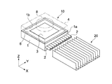
図1は、本発明の一実施の形態に係る気流発生装置とヒートシンクを示す斜視図である。図2は、図1に示す気流発生装置10の断面図である。
FIG. 1 is a perspective view showing an airflow generation device and a heat sink according to an embodiment of the present invention. FIG. 2 is a cross-sectional view of the
気流発生装置10は、上部に矩形の穴1bが開けられた筐体1を備えている。筐体1の穴1bの周囲には、矩形の弾性支持部材6が装着され、この弾性支持部材6により振動板3が支持されている。振動板3、弾性支持部材6及び筐体1によりチャンバ11が形成される。筐体1の側面1aには、チャンバ11内の空気を筐体1の外部に配置されたヒートシンク20に向けて吐出するための複数のノズル2が取り付けられている。ノズル2は、筐体1と一体的に形成されていてもよい。ノズル2は、複数でなく1つであってもよい。
The
筐体1の上部には、振動板3を駆動するためのアクチュエータ5が配置されている。例えば円筒状のヨーク8の内側に、振動板3の振動方向Rに着磁されたマグネット14が内蔵され、マグネット14には、例えば円板状のヨーク18が取り付けられている。このマグネット14、ヨーク8及び18により磁気回路が構成される。マグネット14とヨーク8との間の空間には、コイル17が巻回されたコイルボビン9が出入りするようになっている。すなわち、アクチュエータ5はボイスコイルモータでなる。アクチュエータ5には、給電線16が接続されている。給電線16はカバー4に取り付けられた端子24を介して例えば駆動用のIC等の制御回路13に電気的に接続されている。この制御回路13からアクチュエータ5に電気信号が供給される。
An
ヨーク8は、筐体1の上部を覆うカバー4と一体的に形成されている。しかし、マグネット14により発生する磁束がヨーク8からカバー4へ拡散することを防ぐ観点から、ヨーク8とカバー4とを異なる材料とすることも可能である。コイルボビン9は振動板3の表面に固定されている。このようなアクチュエータ5により、振動板3を矢印R(Z方向)の方向に振動させることができる。
The yoke 8 is formed integrally with the
筐体1は、例えば、樹脂、ゴム、金属、またはセラミックスでなる。樹脂やゴムは成形で作製しやすく量産向きである。また、樹脂やゴムの場合、音の減衰率も高くなり、騒音を抑制することができる。さらに、軽量化に対応できるし、低コストとなる。金属としては、筐体1の放熱を考慮すると、熱伝導性のよい銅やアルミがよい。カバー4の材料も、例えば、樹脂、ゴム、金属、またはセラミックス等でなる。筐体1及びカバー4の材料はそれぞれ同じものであってもよいし、別の材料であってもよい。弾性支持部材6は、例えば樹脂、ゴム等でなる。
The
振動板3は、例えば、樹脂、紙、ゴム、または金属等でなる。振動板3の形状は、図示するような平板状に限らず、スピーカに搭載される振動板のようなコーン状であってもよい。あるいは立体的な形状であってもよい。
The
また、振動板の振動方向Rに垂直な面内での各種形状を図4に示す。図4(A)に示す振動板43のように楕円であってもよいし、図4(B)に示す振動板53のように長円であってもよい。あるいは、図示しないが円形であってもよい。図4(C)〜図4(E)に示す振動板63、73及び83形状は、それぞれ正方形、長方形、及び角が曲線の長方形である。これらのように振動板3等の平面形状は任意形状でよいが、円の場合、金型なども含めて作製が容易である。図4(C)〜図4(E)に示した振動板63、73または83を有する気流発生装置10の筐体1等の平面形状も振動板の形状に合わせて矩形であることが望ましい。例えば、軸流ファン等は回転して送風するため、平面形状は円形である。これに対し、本実施の形態に係る気流発生装置10の振動板は、必ずしも円である必要はないので、図4(A)〜図4(E)に示すようにフレキシブルな形状を実現できる。このように形状がフレキシブルに対応できることにより、例えばPC等の電子機器に気流発生装置10が搭載される場合に、その配置や形状の自由度が高まる。
Various shapes in a plane perpendicular to the vibration direction R of the diaphragm are shown in FIG. It may be oval like the
これらの振動板43等の大きさについては限定されないが、図4(A)〜図4(E)に示すように、例えばrは5〜100[mm]等の範囲が考えられる。ここで、rは、振動板の中心から、最も短い距離にある振動板の周縁部までの距離である。このr=5〜100[mm]という範囲は、気流発生装置10が搭載される電子機器として、例えば小型の携帯電話機器等から、大型のディスプレイ装置までを考慮したものである。より現実的なrとしては、10〜40[mm]である。
Although the size of the
図2を参照して、気流発生装置10の弾性支持部材6の周縁部から、ノズル2の開口端(チャンバ11側の開口端)までの距離dは、例えば1.0〜30.0[mm]であることが好ましい。dが1.0[mm]より小さいと、騒音が人間にとって気になる程度の騒音が発生するからである。これは、振動板3の振動による開口付近に発生する気流と、吸入される気流とがぶつかり合って騒音が発生すると考えられる。一方、dが30.0[mm]より大きいと、筐体1に対して振動板3の上記rが小さいものとなり、非効率となるからである。
Referring to FIG. 2, the distance d from the peripheral edge of the
以上のように構成された気流発生装置10の動作について説明する。
The operation of the
アクチュエータ5に例えば正弦波の交流電圧が印加されると、振動板3は正弦波振動を行う。これにより、チャンバ11内の容積が増減する。チャンバ11の容積変化に伴い、チャンバ11の圧力が変化することでノズル2から空気の流れが脈流として発生する。例えば、振動板3がチャンバ11の容積を増加させる方向に変位すると、チャンバ11の圧力は減少する。これによりノズル2を介して筐体1の外部の空気がチャンバ11内に流れ込む。逆に、振動板3がチャンバ11の容積を減少させる方向に変位すると、チャンバ11の圧力は増加する。これにより、チャンバ11内にある空気がノズル2を介して外部に噴出され、ヒートシンク20にその空気が吹き付けられる。ノズル2から空気が噴出されるときにノズル2の周囲の気圧が低下することにより、当該周囲の空気がノズル2から吐出される空気に巻き込まれる。すなわち、これが合成噴流である。このような合成噴流が、ヒートシンク20に吹き付けられることにより、ヒートシンク20を冷却することができる。
For example, when a sinusoidal AC voltage is applied to the
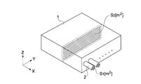
ここで、図2を参照して、振動板3が振動することによりチャンバ11内で圧力変化が発生すると、チャンバ11内で矢印で示す方向(X方向)に気流が発生する。図3は、図1及び図2に示した気流発生装置10のカバー4が外された状態であって、筐体1のみを示す模式的な斜視図である。図2及び図3に示すように、ノズル2の開口面積S1 [m2]、ノズル2内の空気の流量をV1[m3/s]、チャンバ11内で最も流速の大きい気流が発生する箇所の、当該気流にほぼ垂直な面(Y−Z平面)内のチャンバ11内の断面積をS2 [m2]、その箇所の空気の流量をV2[m3/s]とする。この場合において、この気流発生装置10では、次式を満たす。
V2 / S2 ≦ V1 / S1
つまり、チャンバ11内で最も流速の大きい気流の流速が、ノズル2内の開口部で発生する気流の流速以下となるように設定されている。これにより、例えば所望の気体吐出量が得られる大きな振幅で振動板3を振動させても、チャンバ11内における気流によって発生する騒音を低減することができる。チャンバ11内の気流の速度が大きいほど、騒音が大きくなる傾向が見られるので、本実施の形態では、チャンバ11内で発生する気流の流速を極力小さくし、このような気流音による騒音を極力抑えようというものである。しかしながら、流速が小さすぎるということは、所望の空気の吐出量を得るためには、S2を大きくする必要があり、これは筐体1の大型化を招く。したがって、あまり流速を小さくすることはできない。したがって、所望の流量が得られるとともに騒音も低減することができる程度の、チャンバ11内の流速を見出す必要がある。
Here, referring to FIG. 2, when a pressure change occurs in the
V 2 / S 2 ≤ V 1 / S 1
That is, the flow velocity of the air flow having the largest flow velocity in the
ここで、ノズル2が複数ある場合、S1は、各ノズル2の開口面積の合計の面積とする。この場合、チャンバ11内で最も大きい流速は、0.5〜3.0[m2/s]である。0.5[m2/s]より小さいと、所望の気体吐出量を得るためには大きな筐体が必要なるからである。一方、3.0[m2/s]を超えるあたりから、人間にとって気になる程度の騒音が発生するからである。
Here, when there are a plurality of
なお、図1及び図2に示すような気流発生装置10では、チャンバ11内はほぼ直方体状をなし、単純な形状であるのでチャンバ11内においては、だいたいすべての部分で同じ速さ(向きは異なる)の気流が発生する。
In the
図5は、本発明の他の実施の形態に係る気流発生装置を示す断面図である。これ以降の説明では、上記の実施の形態に係る気流発生装置10の部材や機能等について同様のものは説明を簡略または省略し、異なる点を中心に説明する。
FIG. 5 is a cross-sectional view showing an airflow generation device according to another embodiment of the present invention. In the following description, the description of the same members and functions of the
この気流発生装置30の筐体21の内部は、振動板3及び弾性支持部材6により仕切られて第1のチャンバ11a及び第2のチャンバ11bが形成されている。筐体21には、第1及び第2のチャンバ11a及び11bにそれぞれ連通する開口を形成するノズル2a及び2bが設けられている。これら、ノズル2a及び2bはそれぞれ複数であってもよいし、1つずつであってもよい。このような気流発生装置30では、アクチュエータ5に例えば正弦波の交流電圧が印加されることで、振動板3が振動する。振動板3が振動することにより、各チャンバ11a及び11b内の圧力が交互に増減し、ノズル2a及び2bを介して交互に空気が出入りする。つまり、第1のチャンバ11aからノズル2aを介して筐体21外部へ空気が吐出されるときは、外部からノズル2bを介して第2のチャンバ11bへ空気が流入する。逆に、第2のチャンバ11bからノズル2bを介して筐体21外部へ空気が吐出されるときは、外部からノズル2aを介して第1のチャンバ11aへ空気が流入する。
The interior of the
この気流発生装置30においても、図5及び図6に示すように、上記気流発生装置10と同様の理由から、Va2 / Sa2 ≦ Va1 / Sa1、 Vb2 / Sb2 ≦ Vb1 / Sb1を満たすことが要求される。具体的には、各チャンバ11a及び11b内でそれぞれ最も大きな流速が0.5〜3.0[m2/s]となるように設定されている。また、この気流発生装置30においても、距離dが、例えば1.0〜30.0[mm]となるように設定されることが望ましい。
Also in this air
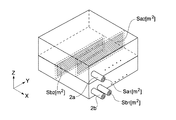
図7のさらに別の実施の形態に係る気流発生装置40に示すように、筐体21の内部に突起する突起部21a及び21b等がある場合、例えば、チャンバ11aでは、突起部21aと振動板3との間で流速が最も大きくなると考えられる。また、チャンバ11bでは、突起部21bと振動板3との間で流速が最も大きくなると考えられる。この突起部21a及び21bは、意識的に形成されたものではなく、例えば気流発生装置40の製造過程において、例えば筐体21の成形時において作られてしまったもの等である。あるいは、突起部21a及び21bは、意図的に形成されたものであってもよい。つまり、このような突起部21a及び21bがある場合であっても、本発明が適用されることになる。
As shown in the
図7に示す気流発生装置40の場合、上記同様、Vc2 / Sc2 ≦ Vc1 / Sc1、 Vd2 / Sd2 ≦ Vd1 / Sd1を満たす。具体的には、各チャンバ11a及び11b内で最も大きな流速が0.5〜3.0[m2/s]となるように設定されている。また、この気流発生装置40においても、図2に示す距離dが、例えば1.0〜30.0[mm]となるように設定されることが望ましい。
In the case of the
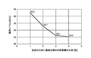
図8は、上記各実施の形態に係る気流発生装置の筐体内に気流が発生したことによる騒音レベル(A特性)を示すグラフである。騒音レベル(A特性)との関係を示すグラフである。A特性とは、人の聴感特性が低い音(周波数の低い音)ほど騒音が感じにくくなることを考慮したものであり、「音圧レベル」をそのような聴感特性に合うように音圧レベルを補正したものである。このグラフでは、ある単位断面積を通過する気流によって発生する騒音レベルが42.3[dB(A)]であった場合に、その単位断面積より大きい断面積を通過する、当該単位断面積を通過した流量と同じ流量の気流による騒音を数値化した実験である。横軸では、単位断面積の2倍、3倍、・・・というように断面積を変えている。このグラフより、断面積が大きくなるほど騒音レベルが低下することがわかる。特に、単位断面積の4倍とすることで、17[dB]近く騒音レベルが低下した。 FIG. 8 is a graph showing the noise level (A characteristic) due to the occurrence of airflow in the housing of the airflow generation device according to each of the above embodiments. It is a graph which shows the relationship with a noise level (A characteristic). A-weighted sound is considered to make it harder to feel noise as sound with lower human audibility characteristics (sound with lower frequency), and the sound pressure level is set so that the “sound pressure level” matches such audible characteristics. Is corrected. In this graph, when the noise level generated by the airflow passing through a certain unit cross-sectional area is 42.3 [dB (A)], the unit cross-sectional area passing through a cross-sectional area larger than that unit cross-sectional area is shown. This is an experiment in which noise caused by airflow at the same flow rate as the flow rate passed through is quantified. On the horizontal axis, the cross-sectional area is changed such as two times, three times the unit cross-sectional area, and so on. From this graph, it can be seen that the noise level decreases as the cross-sectional area increases. In particular, by setting the unit cross-sectional area to 4 times, the noise level was reduced by nearly 17 [dB].
図9は、例えば図5に示した気流発生装置30において、上記距離dと騒音レベル(A特性)との関係を示すグラフである。このグラフから判るように、特に、dが1[mm]以上あれば、騒音が30[dB]未満となり、騒音が低減される。特に、距離dが2〜5[mm]とすることで、騒音レベルが4[dB]程度低減されている。
FIG. 9 is a graph showing the relationship between the distance d and the noise level (A characteristic) in the
本発明は以上説明した実施の形態には限定されるものではなく、種々の変形が可能である。 The present invention is not limited to the embodiment described above, and various modifications are possible.
上記各気流発生装置10、30等は、振動板3を用いて筐体内の気圧変化により脈流として空気を吐出する装置を説明した。しかし、軸流ファン等の層流の空気流を筐体内に発生させてその空気を吐出するような気流発生装置であってもよい。
Each of the
上記各気流発生装置10、30等は、燃料電池の燃料を供給する手段として用いることもできる。具体的には、燃料電池本体の酸素(空気)吸入口と、上記各実施の形態に係る気流発生装置のノズル2とを対向させるように配置すればよい。このようにすれば、気流発生装置から吐出された気流の空気が当該吸入口から酸素燃料として吸入される。
Each of the
1、21…筐体
2、2a、2b…ノズル
3、43、53、63、73、83…振動板
5…アクチュエータ
6…弾性支持部材
10、30、40…気流発生装置
DESCRIPTION OF
Claims (9)
前記筐体内の前記気体に圧力変化を発生させることで、前記第1のチャンバ内に前記第2の気流を発生させるとともに前記第1の開口部に前記第1の気流を発生させながら、該第1の開口部を介して前記気体を吐出させる圧力変化発生機構と
を具備することを特徴とする気流発生装置。 A first opening that generates a first airflow at a first flow velocity, and a second opening that communicates with the first opening and has a second largest flow velocity that is smaller than the first flow velocity. A first chamber in which an air current is generated, and a housing containing gas;
By generating a pressure change in the gas in the housing, the second air stream is generated in the first chamber and the first air stream is generated in the first opening. An airflow generation device comprising: a pressure change generation mechanism that discharges the gas through one opening.
前記圧力変化発生機構は、前記気体を脈流として吐出させるために前記筐体に振動可能に支持された振動体を有することを特徴とする気流発生装置。 The airflow generation device according to claim 1,
The air pressure generation device, wherein the pressure change generation mechanism includes a vibrating body supported by the housing so as to vibrate in order to discharge the gas as a pulsating flow.
前記第2の流速は、0.5〜3.0[m2/s]であることを特徴とする気流発生装置。 The airflow generation device according to claim 1,
The second air flow rate is 0.5 to 3.0 [m 2 / s].
前記第2の流速は、0.5〜3.0[m2/s]であることを特徴とする気流発生装置。 The airflow generation device according to claim 2,
The second air flow rate is 0.5 to 3.0 [m 2 / s].
前記第1の開口部は、前記第1のチャンバ側に端部を有し、
前記振動体は、前記端部から、ほぼ前記第1の気流の方向で1.0〜30.0[mm]に離れた位置に配置された周縁部を有することを特徴とする気流発生装置。 The airflow generation device according to claim 2,
The first opening has an end on the first chamber side,
The vibration body has a peripheral portion arranged at a position separated from the end portion by approximately 1.0 to 30.0 [mm] in the direction of the first air flow.
前記筐体は、
第3の流速で第3の気流が発生する第2の開口部と、
前記第2の開口部に連通し、前記振動体に対して前記第1のチャンバとは反対側に設けられ、前記第3の流速より小さい第4の流速で第4の気流が発生する第2のチャンバと
を有することを特徴とする気流発生装置。 An airflow generation device according to claim 2,
The housing is
A second opening for generating a third airflow at a third flow rate;
The second opening communicates with the second opening and is provided on the opposite side to the first chamber with respect to the vibrating body, and generates a fourth airflow at a fourth flow velocity smaller than the third flow velocity. An airflow generation device characterized by comprising:
前記第4の流速は、0.5〜3.0[m2/s]であることを特徴とする気流発生装置。 The airflow generation device according to claim 6,
The fourth flow velocity is 0.5 to 3.0 [m 2 / s].
前記第2の開口部は、前記第2のチャンバ側に端部を有し、
前記振動体は、前記端部から、ほぼ前記第3の気流の方向で1.0〜30.0[mm]に離れた位置に配置された周縁部を有することを特徴とする気流発生装置。 The airflow generation device according to claim 6,
The second opening has an end on the second chamber side,
The vibration body has a peripheral portion disposed at a position separated from the end by 1.0 to 30.0 [mm] substantially in the direction of the third air flow.
第1の流速で第1の気流が発生する第1の開口部と、前記第1の開口部に連通し、内部で最も大きい流速が前記第1の流速より小さい第2の流速である第2の気流が発生する第1のチャンバとを有し、気体が含まれた筐体と、
前記筐体内の前記気体に圧力変化を発生させることで、前記第1のチャンバ内に前記第2の気流を発生させるとともに前記第1の開口部に前記第1の気流を発生させながら、該第1の開口部を介して前記気体を前記発熱体に向けて吐出させる圧力変化発生機構と
を具備することを特徴とする電子機器。 A heating element;
A first opening that generates a first airflow at a first flow velocity, and a second opening that communicates with the first opening and has a second largest flow velocity that is smaller than the first flow velocity. A first chamber in which an air current is generated, and a housing containing gas;
By generating a pressure change in the gas in the housing, the second air stream is generated in the first chamber and the first air stream is generated in the first opening. An electronic apparatus comprising: a pressure change generation mechanism that discharges the gas toward the heating element through one opening.
Priority Applications (6)
| Application Number | Priority Date | Filing Date | Title |
|---|---|---|---|
| JP2005131875A JP2006310586A (en) | 2005-04-28 | 2005-04-28 | Air current generator and electronic apparatus |
| TW095110963A TW200641318A (en) | 2005-04-28 | 2006-03-29 | Airflow generating device and electronic apparatus |
| EP06006558A EP1718141A3 (en) | 2005-04-28 | 2006-03-29 | Airflow generating device and electronic apparatus |
| CNB2006100777203A CN100399232C (en) | 2005-04-28 | 2006-04-24 | Airflow generating device and electronic apparatus |
| KR1020060037882A KR20060113467A (en) | 2005-04-28 | 2006-04-27 | Airflow generating device and electronic appatratus |
| US11/380,540 US7861767B2 (en) | 2005-04-28 | 2006-04-27 | Airflow generating device and electronic apparatus |
Applications Claiming Priority (1)
| Application Number | Priority Date | Filing Date | Title |
|---|---|---|---|
| JP2005131875A JP2006310586A (en) | 2005-04-28 | 2005-04-28 | Air current generator and electronic apparatus |
Publications (1)
| Publication Number | Publication Date |
|---|---|
| JP2006310586A true JP2006310586A (en) | 2006-11-09 |
Family
ID=36677088
Family Applications (1)
| Application Number | Title | Priority Date | Filing Date |
|---|---|---|---|
| JP2005131875A Pending JP2006310586A (en) | 2005-04-28 | 2005-04-28 | Air current generator and electronic apparatus |
Country Status (6)
| Country | Link |
|---|---|
| US (1) | US7861767B2 (en) |
| EP (1) | EP1718141A3 (en) |
| JP (1) | JP2006310586A (en) |
| KR (1) | KR20060113467A (en) |
| CN (1) | CN100399232C (en) |
| TW (1) | TW200641318A (en) |
Cited By (2)
| Publication number | Priority date | Publication date | Assignee | Title |
|---|---|---|---|---|
| JP2017135973A (en) * | 2016-01-29 | 2017-08-03 | 研能科技股▲ふん▼有限公司 | Piezo actuator |
| CN111867325A (en) * | 2020-07-01 | 2020-10-30 | 南京航空航天大学 | Electronic component heat dissipation system and method based on electromagnetic vibration and evaporative cooling |
Families Citing this family (16)
| Publication number | Priority date | Publication date | Assignee | Title |
|---|---|---|---|---|
| JP5088526B2 (en) * | 2005-04-18 | 2012-12-05 | ソニー株式会社 | Jet generator and electronic device |
| CN101542724A (en) * | 2006-11-30 | 2009-09-23 | 皇家飞利浦电子股份有限公司 | Pulsating cooling system |
| US20080137289A1 (en) * | 2006-12-08 | 2008-06-12 | General Electric Company | Thermal management system for embedded environment and method for making same |
| EP2229536B1 (en) * | 2007-12-07 | 2018-10-24 | Philips Lighting Holding B.V. | Low noise cooling device |
| RU2011119607A (en) * | 2008-10-17 | 2012-11-27 | Конинклейке Филипс Электроникс Н.В. | COOLING DEVICE |
| KR101414640B1 (en) | 2009-09-23 | 2014-07-03 | 엘지전자 주식회사 | Heat-dissipating apparatus |
| US8559173B2 (en) * | 2010-03-15 | 2013-10-15 | Panasonic Corporation | Electronic apparatus provided with cooling structure |
| GB201009338D0 (en) * | 2010-06-04 | 2010-07-21 | Rolls Royce Plc | Fluid transfer arrangement |
| EP2544518A1 (en) * | 2011-07-07 | 2013-01-09 | ABB Research Ltd. | Cooling apparatus for cooling a power electronic device |
| TWI475180B (en) | 2012-05-31 | 2015-03-01 | Ind Tech Res Inst | Synthetic jet equipment |
| CN103987234B (en) * | 2013-02-08 | 2017-08-29 | 台达电子工业股份有限公司 | Heat abstractor |
| TWI539267B (en) * | 2013-12-24 | 2016-06-21 | 台達電子工業股份有限公司 | Heat dissipating apparatus and electronic device |
| CN104735955B (en) * | 2013-12-24 | 2017-08-25 | 台达电子工业股份有限公司 | Heat abstractor and electronic installation |
| US9891677B2 (en) * | 2014-09-11 | 2018-02-13 | Dell Products L.P. | Skin based system cooling using internal system fan |
| CN104501646B (en) * | 2014-12-26 | 2016-08-31 | 李达 | Jet cooling mechanism and jet radiator |
| EP3079034B1 (en) | 2015-04-07 | 2020-09-30 | Vestel Elektronik Sanayi ve Ticaret A.S. | Double-acting synthetic jet module for cooling of electronic devices |
Citations (2)
| Publication number | Priority date | Publication date | Assignee | Title |
|---|---|---|---|---|
| JPH02213200A (en) * | 1989-02-14 | 1990-08-24 | Victor Co Of Japan Ltd | Heat exchanger |
| JPH03116961A (en) * | 1989-09-29 | 1991-05-17 | Victor Co Of Japan Ltd | Heat dissipating device |
Family Cites Families (18)
| Publication number | Priority date | Publication date | Assignee | Title |
|---|---|---|---|---|
| JPS55101800A (en) | 1979-01-25 | 1980-08-04 | Pioneer Electronic Corp | Air pump |
| JPH03168373A (en) * | 1989-11-24 | 1991-07-22 | Nippon Keiki Seisakusho:Kk | Piezoelectric pump control device |
| JPH03222878A (en) * | 1990-01-26 | 1991-10-01 | Mitsubishi Kasei Corp | Piezoelectric vibrator pump |
| EP0732513B1 (en) * | 1995-03-14 | 2003-02-05 | Sulzer Markets and Technology AG | Method and device for active damping of oscillations in detached unstable flows |
| US6123145A (en) * | 1995-06-12 | 2000-09-26 | Georgia Tech Research Corporation | Synthetic jet actuators for cooling heated bodies and environments |
| US5758823A (en) * | 1995-06-12 | 1998-06-02 | Georgia Tech Research Corporation | Synthetic jet actuator and applications thereof |
| JP2000114760A (en) | 1998-10-06 | 2000-04-21 | Toshiba Corp | Cooling structure for electronic equipment |
| KR20000050679A (en) * | 1999-01-13 | 2000-08-05 | 윤종용 | Heat sinking apparatus for electronic equipment |
| US6353295B1 (en) * | 1999-01-20 | 2002-03-05 | Philips Electronics North America Corporation | Lamp electronic ballast with a piezoelectric cooling fan |
| JP2002134975A (en) | 2000-10-23 | 2002-05-10 | Nippon Keiki Works Ltd | Cooling fan |
| WO2003012866A1 (en) | 2001-07-30 | 2003-02-13 | Michael-Georg Bistekos | Device for cooling housings, areas, components, media and the like |
| US6588497B1 (en) * | 2002-04-19 | 2003-07-08 | Georgia Tech Research Corporation | System and method for thermal management by synthetic jet ejector channel cooling techniques |
| JP2004146547A (en) | 2002-10-24 | 2004-05-20 | Hitachi Ltd | Cooling device for electronic apparatus |
| US6937472B2 (en) * | 2003-05-09 | 2005-08-30 | Intel Corporation | Apparatus for cooling heat generating components within a computer system enclosure |
| AU2004258530A1 (en) | 2003-07-07 | 2005-01-27 | Georgia Tech Research Corporation | System and method for thermal management using distributed synthetic jet actuators |
| JP4677744B2 (en) | 2003-11-04 | 2011-04-27 | ソニー株式会社 | Jet generating device, electronic device and jet generating method |
| JP4747657B2 (en) | 2005-04-21 | 2011-08-17 | ソニー株式会社 | Jet generator and electronic device |
| JP4887652B2 (en) | 2005-04-21 | 2012-02-29 | ソニー株式会社 | Jet generator and electronic device |
-
2005
- 2005-04-28 JP JP2005131875A patent/JP2006310586A/en active Pending
-
2006
- 2006-03-29 TW TW095110963A patent/TW200641318A/en not_active IP Right Cessation
- 2006-03-29 EP EP06006558A patent/EP1718141A3/en not_active Withdrawn
- 2006-04-24 CN CNB2006100777203A patent/CN100399232C/en not_active Expired - Fee Related
- 2006-04-27 US US11/380,540 patent/US7861767B2/en not_active Expired - Fee Related
- 2006-04-27 KR KR1020060037882A patent/KR20060113467A/en not_active Application Discontinuation
Patent Citations (2)
| Publication number | Priority date | Publication date | Assignee | Title |
|---|---|---|---|---|
| JPH02213200A (en) * | 1989-02-14 | 1990-08-24 | Victor Co Of Japan Ltd | Heat exchanger |
| JPH03116961A (en) * | 1989-09-29 | 1991-05-17 | Victor Co Of Japan Ltd | Heat dissipating device |
Cited By (3)
| Publication number | Priority date | Publication date | Assignee | Title |
|---|---|---|---|---|
| JP2017135973A (en) * | 2016-01-29 | 2017-08-03 | 研能科技股▲ふん▼有限公司 | Piezo actuator |
| CN111867325A (en) * | 2020-07-01 | 2020-10-30 | 南京航空航天大学 | Electronic component heat dissipation system and method based on electromagnetic vibration and evaporative cooling |
| CN111867325B (en) * | 2020-07-01 | 2021-04-20 | 南京航空航天大学 | Electronic component heat dissipation system and method based on electromagnetic vibration and evaporative cooling |
Also Published As
| Publication number | Publication date |
|---|---|
| KR20060113467A (en) | 2006-11-02 |
| TWI307764B (en) | 2009-03-21 |
| CN100399232C (en) | 2008-07-02 |
| US7861767B2 (en) | 2011-01-04 |
| EP1718141A3 (en) | 2008-07-30 |
| TW200641318A (en) | 2006-12-01 |
| EP1718141A2 (en) | 2006-11-02 |
| US20060245163A1 (en) | 2006-11-02 |
| CN1854981A (en) | 2006-11-01 |
Similar Documents
| Publication | Publication Date | Title |
|---|---|---|
| JP2006310586A (en) | Air current generator and electronic apparatus | |
| JP4747657B2 (en) | Jet generator and electronic device | |
| JP2006305453A (en) | Vibrator, jet generator and electronic equipment | |
| EP1762725B1 (en) | Gas jetting device, electronic device and gas jetting method | |
| JP5088526B2 (en) | Jet generator and electronic device | |
| TWI524840B (en) | Heat dissipating module | |
| KR101219867B1 (en) | Jet generator and electronic device | |
| US20110259557A1 (en) | Heat dissipation apparatus incorporating airflow generator | |
| JP2006310673A (en) | Jet flow generating device, heat sink, cooling device, and electronic apparatus | |
| JP4867324B2 (en) | Heat dissipation device and electronic device | |
| JP4910464B2 (en) | Jet generator and electronic device | |
| JP2007142360A (en) | Radiator device and electronic apparatus | |
| JP4844236B2 (en) | NOZZLE, JET GENERATOR, COOLING DEVICE, AND ELECTRONIC DEVICE | |
| JP2007113530A (en) | Jet flow generator and electronic apparatus | |
| JP2007222727A (en) | Vibration actuator and jet generator | |
| JP2007209845A (en) | Jet flow generator and electronic apparatus | |
| JP2006063900A (en) | Jet generating device and electronic apparatus | |
| JP4900503B2 (en) | Gas ejection device and electronic device | |
| JP2006055741A (en) | Jet flow generator and electronic apparatus | |
| JP2007146730A (en) | Plate drive device, jet generating device and electronic apparatus |
Legal Events
| Date | Code | Title | Description |
|---|---|---|---|
| A621 | Written request for application examination |
Free format text: JAPANESE INTERMEDIATE CODE: A621 Effective date: 20080311 |
|
| A977 | Report on retrieval |
Free format text: JAPANESE INTERMEDIATE CODE: A971007 Effective date: 20091222 |
|
| A131 | Notification of reasons for refusal |
Free format text: JAPANESE INTERMEDIATE CODE: A131 Effective date: 20100112 |
|
| A521 | Written amendment |
Free format text: JAPANESE INTERMEDIATE CODE: A523 Effective date: 20100312 |
|
| A02 | Decision of refusal |
Free format text: JAPANESE INTERMEDIATE CODE: A02 Effective date: 20100413 |