EP1715519B1 - Jet generating device and electronic apparatus - Google Patents
Jet generating device and electronic apparatus Download PDFInfo
- Publication number
- EP1715519B1 EP1715519B1 EP20060008112 EP06008112A EP1715519B1 EP 1715519 B1 EP1715519 B1 EP 1715519B1 EP 20060008112 EP20060008112 EP 20060008112 EP 06008112 A EP06008112 A EP 06008112A EP 1715519 B1 EP1715519 B1 EP 1715519B1
- Authority
- EP
- European Patent Office
- Prior art keywords
- signal
- frequency
- driving mechanism
- generating device
- vibrating
- Prior art date
- Legal status (The legal status is an assumption and is not a legal conclusion. Google has not performed a legal analysis and makes no representation as to the accuracy of the status listed.)
- Not-in-force
Links
Images


Classifications
-
- H—ELECTRICITY
- H05—ELECTRIC TECHNIQUES NOT OTHERWISE PROVIDED FOR
- H05K—PRINTED CIRCUITS; CASINGS OR CONSTRUCTIONAL DETAILS OF ELECTRIC APPARATUS; MANUFACTURE OF ASSEMBLAGES OF ELECTRICAL COMPONENTS
- H05K7/00—Constructional details common to different types of electric apparatus
- H05K7/20—Modifications to facilitate cooling, ventilating, or heating
-
- H—ELECTRICITY
- H10—SEMICONDUCTOR DEVICES; ELECTRIC SOLID-STATE DEVICES NOT OTHERWISE PROVIDED FOR
- H10W—GENERIC PACKAGES, INTERCONNECTIONS, CONNECTORS OR OTHER CONSTRUCTIONAL DETAILS OF DEVICES COVERED BY CLASS H10
- H10W40/00—Arrangements for thermal protection or thermal control
- H10W40/40—Arrangements for thermal protection or thermal control involving heat exchange by flowing fluids
- H10W40/43—Arrangements for thermal protection or thermal control involving heat exchange by flowing fluids by flowing gases, e.g. forced air cooling
Definitions
- the present invention relates to a vibrator for vibrating gas for generating a jet of the gas, a jet generating device including the vibrator, and an electronic apparatus including the jet generating device.
- the most general index indicating the performance of a heat-dissipating system is heat resistance.
- Ta ambient temperature (outside air temperature) when is an air-cooling system is used.
- a heat-dissipating system providing good performance is one having a small heat resistance.
- a heat-dissipating system having a heat resistance of less than 1.5 [K/W] is used.
- a typical heat resistance is less than 0.3 [K/W].
- a heat-dissipating system which makes use of forceful air cooling basically includes a heat exchanger exchanging heat between a heat source and outside air and an air blower which sends the outside air to the heat exchanger.
- the heat resistance of this heat-dissipating system may be reduced by increasing efficiency of the heat exchanger or by increasing an air discharge amount of the air blower. For example, by putting thought in the material and structure of a radiating fin or by increasing the surface area of the radiating fin, the efficiency of the heat exchange can be increased.
- the air discharge amount can be increased by, for example, increasing the rotational speed or diameter of the fan.
- 2-213200 and 3-116961 include a vibrating plate which roughly divides space in a chamber in two, a resilient member disposed in the chamber and supporting the vibrating plate, and a unit which vibrates the vibrating plate.
- a vibrating plate which roughly divides space in a chamber in two
- a resilient member disposed in the chamber and supporting the vibrating plate
- a unit which vibrates the vibrating plate.
- the vibrating plate when the vibrating plate is displaced upwards, the volume of an upper space of the chamber is reduced. Therefore, the pressure in the upper space is increased. Since the upper space is connected to the outside air through a suction-exhaust opening, a portion of the air in the upper space is discharged to the outside air by the pressure increase in the upper space. At this time, the volume of a lower space that is opposite to the upper space (the vibrating plate is disposed between the lower space and the upper space) is increased, causing the pressure in the lower space to decrease.
- the pressure reduction in the lower space causes a portion of the outside air existing near the suction-exhaust opening to be sucked into the lower space.
- the volume of the upper space of the chamber is increased. Therefore, the pressure in the upper space is decreased. Since the upper space is connected to the outside air through the suction-exhaust opening, the pressure reduction in the upper space causes a portion of the outside air existing near the suction-exhaust opening to be sucked into the upper space.
- the volume of the lower space that is opposite to the upper space (the vibrating plate is disposed between the lower space and the upper space as mentioned above) is decreased, causing the pressure in the lower space to increase.
- the pressure increase in the lower space causes a portion of the air in the lower space to be discharged to the outside air.
- the vibrating plate is driven by, for example, an electromagnetic driving method. Accordingly, by reciprocating the vibrating plate, the discharging of the air in the chamber to the outside air and the sucking of the outside air into the chamber are periodically repeated.
- Pulsating air induced by a periodic reciprocating movement of the vibrating plate is blown against a heating element such as the radiating fin, so that the temperature boundary layer at the surface of the radiating fin is efficiently broken, as a result of which the radiating fin is cooled with high efficiency.
- a dynamic fluid spray jet delivery system for cooling semiconductor chips.
- a cooling fluid may be sprayed on hot components to be cooled.
- a spray delivery system has an activator configured to move the sprayer among positions for spraying the cooling fluid on different components.
- US 6.367,470 B1 discloses a nebulizer for a medical use. It determines the duration of a pulse of atomization during inspiration by a patient. The duration of the pulse is calculated ori the basis of the tidal volume measured by a tidle volume measuring element. Therefore, first a tidle volume as well as a duration of inspiration of a patient have to be performed.
- US 3,373,752 disclosed a jet generating device for ultrasonic cleaning of surfaces.
- an air discharge amount can be increased by increasing the area or vibration amplitude of the vibrating plate.
- the size (volume) of the device is limited, such as when a heating element in a small apparatus is cooled, there is a limit as to how large the area or the vibration amplitude of the vibrating plate can be made.
- increasing the area or the vibration amplitude of the vibrating plate increases electrical power consumption of the device.
- a driving frequency of the vibrating plate is in a non-audible area of approximately 10 Hz.
- the air velocity in front of the radiating fin differs depending upon the frequency of the vibrating plate, with the air velocity being greater at 19 Hz than at 15 Hz (lower right column on page 3 of the specification).
- the driving frequency is merely set at a lower non-audible area, noise is restricted, but an air discharge area per unit time is reduced in correspondence with the lower frequency.
- a jet generating device which can increase heat-dissipation capability while restricting electrical power consumption as a result of optimizing a driving frequency of a vibrating member, and an electronic apparatus including the jet generating device.
- a jet generating device including a housing having an opening and containing gas therein, a vibrating member which is supported by the housing so that the vibrating member is capable of vibrating and which vibrates the gas to discharge the gas as pulsating gas through the opening, a driving mechanism for driving the vibrating member in accordance with an electrical signal, and a drive controller which generates the electrical signal at a fundamental frequency at which an input impedance of the driving mechanism is substantially a maximum and which outputs the generated electrical signal to the driving mechanism.
- a driving method of the driving unit may make use of, for example, an electromagnetic action, a piezoelectric action, or an electrostatic action.
- the type of gas which may be used is not only air, but also nitrogen, helium gas, argon gas, or other types of gas.
- the vibrating member may have a three-dimensional structure instead of a structure having a flat-plate form.
- the vibrating plate may have a structure in which, for example, a side plate or a rib is mounted to the vibrating plate in order to increase rigidity.
- the vibrating member may have any form which is not limited to such a purpose.
- the shape of the vibrating member in a plane perpendicular to the direction of vibration of the vibrating member may be, for example, circular, elliptical, or rectangular.
- the drive controller sets the fundamental frequency lower than a minimum resonance frequency of the vibrating member.
- the input impedance may become greater than the aforementioned maximum value. Accordingly, the vibrating member may be driven at such a high frequency range. In such a case, the vibration amplitude of the vibrating member becomes extremely small. This may make it impossible to obtain a predetermined gas discharge amount.
- the vibration amplitude can be set at its maximum value, so that, according to the embodiment of the present invention, the fundamental frequency is set near the minimum resonance frequency of the vibrating member.
- the drive controller includes an amplifier and a signal generator, the signal generator generating a sinusoidal signal, a voltage pulse signal, or an electrical current pulse signal, each signal having a fundamental frequency at which an input impedance of the amplifier is substantially a maximum, the amplifier amplifying the generated signal and outputting the amplified signal to the driving mechanism.
- the signal generator be such that a total harmonic distortion factor of the electrical signal is less than 10%.
- an electronic apparatus including a heating element, a housing having an opening and containing gas therein, a vibrating member which is supported by the housing so that the vibrating member is capable of vibrating and which vibrates the gas to discharge the gas as pulsating gas towards the heating element through the opening, a driving mechanism for driving the vibrating member in accordance with an electrical signal, and a drive controller which generates the electrical signal at a frequency range including a fundamental frequency at which an input impedance of the driving mechanism is substantially a maximum and which outputs the generated electrical signal to the driving mechanism.
- Examples of the electronic apparatus are a computer (which may be a laptop computer or a desktop computer when the computer is a personal computer), a Personal Digital Assistance (PDA), an electronic dictionary, a camera, a display device, an audio/visual device, a cellular phone, a game device, a car navigator system, a robot apparatus, and other electronic products.
- a computer which may be a laptop computer or a desktop computer when the computer is a personal computer
- PDA Personal Digital Assistance
- an electronic dictionary a camera
- a display device an audio/visual device
- a cellular phone a game device
- a car navigator system a robot apparatus, and other electronic products.
- the heating element may be an electronic part, such as an IC or a resistor, a radiating fin (heat sink), or any other element as long as it generates heat.
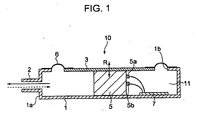
- FIG. 1 is a sectional view of a jet generating device according to an embodiment of the present invention.
- a jet generating device 10 includes, for example, a housing 1 having a rectangular hole 1b in an upper portion of the housing 1.
- An annular resilient supporting member 6 is mounted to a periphery of the hole 1b of the housing 1, and supports a vibrating plate 3 serving as a vibrating member.
- a chamber 11 is formed in the housing 1 by disposing the vibrating plate 3 and the resilient supporting member 6 so as to cover the hole 1b of the housing 1.
- a plurality of nozzles 2 for discharging air in the chamber 11 towards a heating element (not shown), such as a radiating fin, disposed outside the housing 1 are mounted to a side surface 1a of the housing 1.
- the nozzles 2 may be integrated to the housing 1. Alternatively, only openings instead of the nozzles 2 may be formed in the side surface 1a.
- the housing 1 has, for example, a rectangular parallelepiped shape.
- the nozzles 2 are formed in the side surface 1a of the housing 1 so as to be arranged in the direction perpendicular to the plane of Fig. 1 .
- the size of the housing 1 in a direction perpendicular to the plane of Fig. 1 is set, for example, in accordance with the size of the heating element, and the number of nozzles 2 can be set in accordance with the area of the side surface 1a of the housing 1.
- the resilient supporting member 6 and the vibrating plate 3 may be, for example, rectangular in accordance with the rectangular parallelepiped shape of the housing 1, they may be circular or elliptical.
- the vibrating plate 3 is illustrated as having the shape of a flat plate, it may be cone-shaped like a vibrating plate having a speaker mounted thereto.
- the housing 1 is formed of, for example, resin, rubber, metal, or ceramic. Resin and rubber facilitate the formation of the housing 1 and are suited for mass-production. In addition, resin and rubber can increase a sound attenuation factor and can thus restrict noise, and can be used to reduce weight and costs. Considering heat dissipation of the housing 1, it is desirable that the metal be copper or aluminum having high thermal conductivity.
- the vibrating plate 3 is formed of, for example, resin, paper, rubber, or metal.
- the resilient supporting member 6 is formed of, for example, resin or rubber.
- a driving mechanism 5 for driving the vibrating plate 3 is disposed in the chamber 11.
- a circuit board 7 for outputting an electrical signal to the driving mechanism 5 is electrically connected to input terminals 5a and 5b of the driving mechanism 5.
- the circuit board 7 may be disposed outside the circuit board 7.
- the driving mechanism 5 converts electrical energy of the electrical signal into mechanical energy, and is, for example, a voice coil motor making use of electromagnetic force.
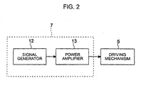
- Fig. 2 is a block diagram of a structure of the circuit board 7.
- the circuit board 7 includes, for example, a signal generator 12 which generates, for example, a sinusoidal electrical signal and a power amplifier 13 which amplifies electrical power of the electrical signal output from the signal generator 12.
- the electrical signal amplified by the power amplifier 13 is input to the driving mechanism 5.
- the vibrating plate 3 undergoes sinusoidal vibration, causing the volume of the chamber 11 to increase or decrease.
- the change in the volume of the chamber 11 changes the pressure in the chamber 11, causing airflow to be produced as pulsating airflow from the nozzles 2.
- the vibrating plate 3 is displaced in the direction in which the volume of the chamber 11 is increased, the pressure in the chamber 11 is reduced. This causes air outside the housing 1 to flow into the chamber 11 through the nozzles 2.
- the vibrating plate 3 is displaced in the direction in which the volume of the chamber 11 is reduced, the pressure in the chamber 11 is increased.
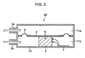
- Fig. 3 is a sectional view of a jet generating device of a form having two chambers.
- a jet generating device 20 chambers 11a and 11b are formed by a vibrating plate 3 and a resilient supporting member 6, which are disposed in a housing 21.
- the chamber 11a is connected to the outside of the housing 21 through a nozzle 2a.
- the chamber 11b is connected to the outside of the housing 21 through a nozzle 2b.
- vertically vibrating in Fig. 3
- the vibrating plate 3 causes the volumes of the chambers 11a and 11b to be alternately increased and decreased, so that air is alternately discharged through the nozzles 2a and 2b.
- the discharge amount can be increased in proportion to the vibration amplitude. Since the discharge amount is also proportional to the frequency, the higher the driving frequency, the larger the discharge amount. However, in such a mechanical vibrating system, in general, the vibration amplitude is reduced as the vibration frequency is increased. Therefore, the discharge amount will not be increased indefinitely by increasing the frequency. In other words, there is an optimal frequency at which the discharge amount is a maximum.
- This frequency depends upon, for example, the size and structure of, for example, the jet generating device 10, the mass of the vibrating plate 3, the resiliency of the resilient supporting member 6, the size and shape of the openings in the nozzles 2, and a discharge-side load (such as a flow path resistance of a radiating fin).
- the inventor has found that there is a relationship between the optimum frequency and an input impedance of the driving mechanism 5 independently of the structure of the jet generating device 10, etc.
- the inventor has found that, when, while maintaining at a constant value electrical energy of an alternating signal applied to the driving mechanism 5, the frequency thereof is varied, the frequency at which the air discharge amount from the jet generating device 10, etc., is a maximum, that is, heat resistance is a minimum matches the frequency at which the magnitude of the input impedance of the driving mechanism 5 is a maximum.
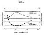
- Fig. 4 is a graph showing relationships among driving frequency, heat resistance, and input impedance of the driving mechanism 5.
- electrical power consumed by the driving mechanism 5 is constant in, for example, a heat-dissipating system in which the jet generating device 20 shown in Fig. 3 and a suitable radiating fin (not shown) are combined.
- the electrical power consumption is, for example, 0.5 [W], and input frequency is varied from 10 [Hz] to 120 [Hz] while the electrical power consumption is kept constant.
- the vibrating plate 3 is one whose surface contributing to air vibration has a diameter of approximately 50 [mm].
- the input impedance of the driving mechanism 5 is a maximum and the heat resistance is a minimum.
- the heat resistance becomes very high, thereby reducing heat-dissipation efficiency. Accordingly, when the driving mechanism 5 is driven at the frequency at which the input impedance of the driving mechanism 5 is a maximum, it is possible to form a heat-dissipating system having maximum heat-dissipation capability with minimum electrical power consumption.
- the driving frequency can be easily adjusted to a frequency near the frequency at which the magnitude of the input impedance is a maximum.
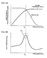
- Figs. 5A and 5B are graphs showing relationship among frequency, frequency amplitude, and sound pressure level of the vibrating plate (such as a speaker) and relationship between the frequency of the vibrating plate and the input impedance, respectively.
- a frequency range used by a general speaker is one which is higher than a minimum resonance frequency f0 and where the sound pressure level is substantially constant.
- the vibration amplitude of the vibrating plate is constant regardless of the frequency, the lower the frequency, the lower the sound pressure level.
- the sound pressure level is substantially flat with respect to the frequency.
- a driving frequency at which the input impedance of the voice coil, which vibrates, for example, a speaker, is a maximum value X falls within a frequency range near the minimum resonance frequency f0.
- the jet generating device 10 at a frequency which is less than f0, since the vibration amplitude of the vibrating plate is constant, the lower the frequency, the lower the air discharge amount.
- the vibration amplitude is reduced in inverse proportion to the square of the frequency, the higher the frequency, the lower the air discharge amount. Therefore, performing driving at a frequency near f0 causes a maximum air discharge amount to be obtained.
- driving the driving mechanism 5 at a frequency at which the input impedance of the driving mechanism 5 is a maximum makes it possible to operate the heat-dissipating system with limited electrical consumption and maximum cooling efficiency.
- the driving mechanism 5 is typically driven with the optimal frequency. Therefore, it is possible to provide a heat-dissipating system allowing high yield without variations in performance.
- the power amplifier 13 may take the form of a circuit which generates at output terminals of the power amplifier 13 voltage or electrical current which is substantially proportional to voltage applied to input terminals of the power amplifier 13.
- the power amplifier 13 may have the form of a circuit which generates at the output terminals of the power amplifier 13 voltage or electrical current which is substantially proportional to electrical current flowing between the input terminals of the power amplifier 13.
- the power amplifier 13 may be a linear amplifier which can supply a substantially constant voltage or electrical current regardless of the magnitude of a load (that is, the input impedance of the driving mechanism 5) connected to the output terminals of the power amplifier 13.
- an output method of the power amplifier 13 may be a Single Ended Push Pull (SEEP) method for driving an end of the load at ground potential, it may also be a Balanced Transformerless Amplifier (BTL) method for subjecting the load to reversed-phase driving with two power amplifiers.
- SEEP Single Ended Push Pull
- BTL Balanced Transformerless Amplifier
- a CR series circuit or an LR parallel circuit may be additionally inserted.
- a sinusoidal signal generator 22 which generates the aforementioned sinusoidal signal may be used as the signal generator.
- a voltage or an electrical current signal which varies sinusoidally with time is generated at output terminals of the sinusoidal signal generator 22, and a fundamental frequency of the sinusoidal signal generated by the sinusoidal signal generator 22 is set near the frequency at which the input impedance of the driving mechanism 5 is a maximum.
- the sinusoidal signal having a frequency near the frequency at which the input impedance of the driving mechanism 5 is a maximum is generated to drive the driving mechanism 5 while substantially maintaining the waveform of the signal.
- the sinusoidal signal generator 22 is, for example, a CR oscillator.
- the CR oscillator may be one making use of a time constant based on a capacitor and a resistor, such as a Wien bridge oscillator, a state variable oscillator, or a phase-shift oscillator, or any other type of oscillator as long as it can allow oscillation frequency to be relatively easily controlled from the outside.
- the sinusoidal signal generator 22 is a CR oscillator
- a total harmonic distortion factor of an output signal be less than 10%. Since the output signal of the CR oscillator is input to the driving mechanism 5 through the linear power amplifier, the output signal is input to the driving mechanism 5 while substantially preserving the waveform of the oscillator. Since the displacement of the vibrating plate 3 is substantially proportional to the magnitude of an input electrical current of the driving mechanism 5, when a large amount of harmonic component is included in the input signal of the driving mechanism 5, an amount of harmonic component included in the vibration of the vibrating plate 3 is also large. When the harmonic component includes a frequency component having high audibility, noise level may become high.
- a sinusoidal signal whose total harmonic distortion factor is as small as possible is typically used as the output signal of the CR oscillator. If the total harmonic distortion factor is less than 10%, the noise will not bother anyone under ordinary operation conditions. If, for example, a suitable gain control circuit is used in the CR oscillator, such a distortion factor can be relatively easily obtained.
- a signal generator 23 which generates a rectangular, a triangular, or a sawtooth signal is used as the sinusoidal signal generator 22.
- An output signal of the rectangular/triangular/sawtooth signal generator 23 is passed through a low-pass filter 27 for reducing a harmonic component, thereby making it possible to produce a low-distortion sinusoidal signal whose harmonic component is low.
- the rectangular/triangular/sawtooth signal generator 23 may use a circuit type which is generally known with regard to the above-described CR oscillator.
- the low-pass filter 27 attenuate the amplitude of the harmonic wave to less than 1/10 of the original amplitude. It is further desirable that an active filter or a switch capacitor filter having excellent attenuation characteristics be used in the low-pass filter 27.
- the order and characteristics (Bessel type, Butterworth type, Chebyshev type, etc.) are properly selected in accordance with a typical output distortion factor.
- the sinusoidal signal generator may use a digital circuit instead of an analog circuit including a CR type.
- an amplitude data generator 24 which generates a signal whose sinusoidal wave amplitude is digitized and a digital-to-analog (D/A) converter 28 which converts the amplitude data to the magnitude of a voltage or electrical current are used.
- D/A digital-to-analog
- the amplitude data generator 24 may make use of a solid-state memory which previously stores amplitude data or may have a structure which generates sinusoidal function data by digital computation.
- the number of bits and samplings of the digital data may be properly selected in accordance with a typical distortion factor.
- the digitally generated sinusoidal signal includes quantum noise produced by sampling frequency.
- a low-pass filter which is an analog or a digital circuit may be inserted between the D/A converter 28 and the power amplifier 13.
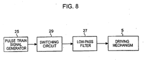
- a pulse train signal generator 25 may be used as the digital sinusoidal signal generator.
- the sinusoidal signal generator 22 includes the pulse train signal generator 25 and a low-pass filter 27, the pulse train signal generator 25 generating a voltage pulse train whose voltage changes continually with time or an electrical current pulse train whose electrical current changes continually with time.
- an output waveform of the D/A converter changes similarly to the waveform of a signal input to the driving mechanism 5, whereas signals generated by the pulse train signal generator 25 are such that a voltage or an electrical current pulse duration time changes with their amplitudes being substantially constant.
- the pulse train generated at the pulse train signal generator 25 that is output may be a pulse train whose pulse interval changes with a constant pulse width or a pulse train which is subjected to pulse width modulation so as to have a pulse width that changes with a period being constant. For either pulse train, properly controlling the ratio between the pulse width and the period with every sampling period makes it possible to output a sinusoidal signal to the output of the low-pass filter 27.
- the pulse train generated at the pulse train signal generator 25 may have a constant amplitude (voltage or electrical current), it may be a signal which changes with time.
- the power amplifiers 13 described with reference to Figs. 7A to 7C are linear amplifiers which can each supply a substantially constant voltage or electrical current regardless of the magnitude of a load (that is, the input impedance of the driving mechanism 5) connected to the output terminals.
- the power amplifier 13 may be a non-linear amplifier or may be formed as a switching circuit 29.
- the above-described pulse train signal generator 25 may be used as the signal generator. That is, a fundamental frequency of a pulse train generated by the pulse train signal generator 25 is set at a frequency which is near the frequency at which the input impedance of the driving mechanism 5 is a maximum.
- the switching circuit 29, which serves as the amplifier, generates at its output terminals a voltage pulse or an electrical current pulse in synchronism with an input signal.
- the low-pass filter 27 may be omitted when quantum noise included in a pulse train signal is small.
- Fig. 9 shows an exemplary structure of the switching circuit 29 shown in Fig. 8 .
- the structure is an example in which one of the input terminals of the driving mechanism 5 is driven at ground potential.
- a pulse train signal from the pulse train signal generator 25 is input to a differential amplifier for the switching circuit 29, the signal is converted into a digital signal in synchronism with a timing thereof.
- a non-inverting output and an inverting output of the differential amplifier are input to a gate driver to generate a typical timing signal for turning on or off switching elements (MOS-FETs).
- MOS-FETs turning on or off switching elements
- the one of the switching elements is turned off, and the other of the switching elements is turned on.
- This causes a signal in synchronism with the pulse train signal from the pulse train signal generator 25 to be output to an output of the switching circuit 29. Since a large amount of harmonic component is included in this signal, the harmonic component is attenuated by, for example, a low-pass filter 27 including an inductor and a capacitor. This makes it possible to apply a sinusoidal signal to the input terminals of the driving mechanism 5.
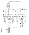
- Fig. 10 shows an example in which an output of the pulse train signal generator 25 is input to two switching circuits 29a and 29b.
- the two switching circuits 29a and 29b have structures that are similar to the structure of the switching circuit 29 shown in Fig. 9 .
- Low-pass filters 27a and 27b are connected to outputs of the respective switching circuits 29a and 29b.
- Such a structure makes it possible to double the vibration amplitude with supply voltages (+V and -V) that are the same as those shown in Fig. 9 .
Landscapes
- Physics & Mathematics (AREA)
- Thermal Sciences (AREA)
- Engineering & Computer Science (AREA)
- Microelectronics & Electronic Packaging (AREA)
- Cooling Or The Like Of Electrical Apparatus (AREA)
- Reciprocating Pumps (AREA)
- Apparatuses For Generation Of Mechanical Vibrations (AREA)
Description
- The present invention relates to a vibrator for vibrating gas for generating a jet of the gas, a jet generating device including the vibrator, and an electronic apparatus including the jet generating device.
- An increase in the scale and speed of large scale integrated circuits (LSI circuits) in recent years have caused electrical power consumption of the LSI circuits to increase year after year. Since most of the electrical power consumed by the LSI circuits is converted into heat energy, the increase in electrical power consumption has led to an increase in the heat value of the LSI circuits. With regard to a system using such an LSI circuit having high electrical power consumption, effort is being made to increase performance of a heat-dissipating system so that the temperature of the LSI circuit does not exceed its maximum operating temperature.
- The most general index indicating the performance of a heat-dissipating system is heat resistance. When the temperature of a heat source whose heat value is P[W] is T (°C or K) as a result of being cooled by a certain heat-dissipating system, a heat resistance Rth[K/W] of the heat-dissipating system is expressed by the following formula:

Here, Ta is ambient temperature (outside air temperature) when is an air-cooling system is used. In order not to increase the temperature of the heat source even if the heat value is high, the heat resistance of the heat-dissipating system is made small. In other words, a heat-dissipating system providing good performance is one having a small heat resistance. For example, in order for a maximum heat value to maintain the temperature of a 20[W] LSI circuit equal to or less than 70°C, under an environment in which the outside air temperature has a maximum value of 40°C, a heat-dissipating system having a heat resistance of less than 1.5 [K/W] is used. When the heat value of the LSI circuit is increased to 100 [W], a typical heat resistance is less than 0.3 [K/W]. - A heat-dissipating system which makes use of forceful air cooling basically includes a heat exchanger exchanging heat between a heat source and outside air and an air blower which sends the outside air to the heat exchanger. The heat resistance of this heat-dissipating system may be reduced by increasing efficiency of the heat exchanger or by increasing an air discharge amount of the air blower. For example, by putting thought in the material and structure of a radiating fin or by increasing the surface area of the radiating fin, the efficiency of the heat exchange can be increased. In a system using an axial fan which rotates as the air blower, the air discharge amount can be increased by, for example, increasing the rotational speed or diameter of the fan.
- However, in forceful convection of air with such a fan, a temperature boundary layer at a surface of the fin is produced at a downstream side of the fin, thereby giving rise to the problem that heat from the radiating fin is not efficiently removed. This problem may be solved by, for example, reducing the thickness of the temperature boundary layer as a result of increasing fan air velocity. However, increasing the rotational speed of the fan for the purpose of increasing the fan air velocity causes noise to be generated, such as noise from a fan bearing or noise of the wind produced by the fan.
- Methods using a vibrating plate that reciprocates periodically (refer to, for example,
Japanese Unexamined Patent Application Publication Nos. 2000-223871 Fig. 2 ),2000-114760 Fig. 1 ),2-213200 Fig. 1 ), and3-116961 Figs. 3 and 11)) are available as methods which efficiently allow heat from a radiating fin to escape to outside air by destroying the temperature boundary layer without using a fan as an air blower. Of devices in these four documents, in particular, the devices inJapanese Unexamined Patent Application Publication Nos. 2-213200 3-116961 - From
US 2005/0056030 Al a dynamic fluid spray jet delivery system is known for cooling semiconductor chips. A cooling fluid may be sprayed on hot components to be cooled. Thereby, a spray delivery system has an activator configured to move the sprayer among positions for spraying the cooling fluid on different components. -
US 6.367,470 B1 discloses a nebulizer for a medical use. It determines the duration of a pulse of atomization during inspiration by a patient. The duration of the pulse is calculated ori the basis of the tidal volume measured by a tidle volume measuring element. Therefore, first a tidle volume as well as a duration of inspiration of a patient have to be performed. -
US 3,373,752 disclosed a jet generating device for ultrasonic cleaning of surfaces. - In a device using a vibrating plate which reciprocates, such as the devices in the aforementioned four documents, in principle, an air discharge amount can be increased by increasing the area or vibration amplitude of the vibrating plate. However, when the size (volume) of the device is limited, such as when a heating element in a small apparatus is cooled, there is a limit as to how large the area or the vibration amplitude of the vibrating plate can be made. In addition, increasing the area or the vibration amplitude of the vibrating plate increases electrical power consumption of the device.
- In, for example,
Japanese Unexamined Patent Application Publication No. 2-213200 Japanese Unexamined Patent Application Publication No. 3-116961 page 3 of the specification).
However, when the driving frequency is merely set at a lower non-audible area, noise is restricted, but an air discharge area per unit time is reduced in correspondence with the lower frequency. - In view of the aforementioned problems, it is desirable to provide a jet generating device which can increase heat-dissipation capability while restricting electrical power consumption as a result of optimizing a driving frequency of a vibrating member, and an electronic apparatus including the jet generating device.
- According to an embodiment of the present invention, there is provided a jet generating device including a housing having an opening and containing gas therein, a vibrating member which is supported by the housing so that the vibrating member is capable of vibrating and which vibrates the gas to discharge the gas as pulsating gas through the opening, a driving mechanism for driving the vibrating member in accordance with an electrical signal, and a drive controller which generates the electrical signal at a fundamental frequency at which an input impedance of the driving mechanism is substantially a maximum and which outputs the generated electrical signal to the driving mechanism.
- When the vibrating member is driven at a frequency near the fundamental frequency at which the input impedance is a substantially maximum value, heat resistance when a heating element is subjected to heat dissipation is a minimum value. In other words, the inventor has found out that, the frequency when the heat resistance is a minimum value matches the frequency at which the input impedance of the driving mechanism is substantially a maximum. The smaller the heat resistance, the higher the performance of the jet generating device. Therefore, according to the embodiment of the present invention, it is possible to provide a maximum heat-dissipation capability with minimum electrical power consumption.
- A driving method of the driving unit may make use of, for example, an electromagnetic action, a piezoelectric action, or an electrostatic action.
- The type of gas which may be used is not only air, but also nitrogen, helium gas, argon gas, or other types of gas.
- The vibrating member may have a three-dimensional structure instead of a structure having a flat-plate form. For example, the vibrating plate may have a structure in which, for example, a side plate or a rib is mounted to the vibrating plate in order to increase rigidity. However, the vibrating member may have any form which is not limited to such a purpose. In addition, the shape of the vibrating member in a plane perpendicular to the direction of vibration of the vibrating member may be, for example, circular, elliptical, or rectangular.
- In one form, the drive controller sets the fundamental frequency lower than a minimum resonance frequency of the vibrating member. For a high frequency range where a sound pressure level of the vibrating member is low (that is, a frequency range which is sufficiently higher than a minimum resonance frequency), the input impedance may become greater than the aforementioned maximum value. Accordingly, the vibrating member may be driven at such a high frequency range. In such a case, the vibration amplitude of the vibrating member becomes extremely small. This may make it impossible to obtain a predetermined gas discharge amount.
In contrast, in a low frequency range near the minimum resonance frequency, even if electrical power is the same as when the vibrating member is driven at the high frequency range, the vibration amplitude can be set at its maximum value, so that, according to the embodiment of the present invention, the fundamental frequency is set near the minimum resonance frequency of the vibrating member. - In still another form, more specifically, the drive controller includes an amplifier and a signal generator, the signal generator generating a sinusoidal signal, a voltage pulse signal, or an electrical current pulse signal, each signal having a fundamental frequency at which an input impedance of the amplifier is substantially a maximum, the amplifier amplifying the generated signal and outputting the amplified signal to the driving mechanism. In this case, it is desirable that the signal generator be such that a total harmonic distortion factor of the electrical signal is less than 10%. By setting the harmonic distortion factor at a value which is less than 10%, a harmonic component providing high auditory sensation characteristics is reduced, so that the noise is at a level that does not bother human beings.
- According to another embodiment of the present invention, there is provided an electronic apparatus including a heating element, a housing having an opening and containing gas therein, a vibrating member which is supported by the housing so that the vibrating member is capable of vibrating and which vibrates the gas to discharge the gas as pulsating gas towards the heating element through the opening, a driving mechanism for driving the vibrating member in accordance with an electrical signal, and a drive controller which generates the electrical signal at a frequency range including a fundamental frequency at which an input impedance of the driving mechanism is substantially a maximum and which outputs the generated electrical signal to the driving mechanism.
- Examples of the electronic apparatus are a computer (which may be a laptop computer or a desktop computer when the computer is a personal computer), a Personal Digital Assistance (PDA), an electronic dictionary, a camera, a display device, an audio/visual device, a cellular phone, a game device, a car navigator system, a robot apparatus, and other electronic products.
- The heating element may be an electronic part, such as an IC or a resistor, a radiating fin (heat sink), or any other element as long as it generates heat.
- According the embodiments and forms of the present invention, it is possible to enhance heat-dissipation capability while restricting electrical power consumption.
-
-
Fig. 1 is a sectional view of a jet generating device according to an embodiment of the present invention; -
Fig. 2 is a block diagram of a structure of a circuit board; -
Fig. 3 is a sectional view of a jet generating device of a form having two chambers; -
Fig. 4 is a graph showing relationships among driving frequency, heat resistance, and input impedance of a driving mechanism; -
Figs. 5A and 5B are graphs showing relationship among frequency, frequency amplitude, and sound pressure level of a vibrating plate and relationship between the frequency of the vibrating plate and the input impedance, respectively. -
Fig. 6 is a block diagram of an example in which a sinusoidal signal generator is used as a signal generator; -
Figs. 7A to 7C are block diagrams of specific examples of the sinusoidal signal generator shown inFig. 6 ; -
Fig. 8 is a block diagram of an example in which a switching circuit is used as a power amplifier; -
Fig. 9 shows an exemplary structure of the switching circuit shown inFig. 8 ; and -
Fig. 10 shows a different exemplary structure of the switching circuit shown inFig. 8 . - Embodiments of the present invention will hereunder be described with reference to the drawings.
-
Fig. 1 is a sectional view of a jet generating device according to an embodiment of the present invention. Ajet generating device 10 includes, for example, ahousing 1 having arectangular hole 1b in an upper portion of thehousing 1. An annular resilient supportingmember 6 is mounted to a periphery of thehole 1b of thehousing 1, and supports a vibratingplate 3 serving as a vibrating member. A chamber 11 is formed in thehousing 1 by disposing the vibratingplate 3 and the resilient supportingmember 6 so as to cover thehole 1b of thehousing 1. A plurality ofnozzles 2 for discharging air in the chamber 11 towards a heating element (not shown), such as a radiating fin, disposed outside thehousing 1 are mounted to aside surface 1a of thehousing 1. Thenozzles 2 may be integrated to thehousing 1. Alternatively, only openings instead of thenozzles 2 may be formed in theside surface 1a. - The
housing 1 has, for example, a rectangular parallelepiped shape. For example, thenozzles 2 are formed in theside surface 1a of thehousing 1 so as to be arranged in the direction perpendicular to the plane ofFig. 1 . The size of thehousing 1 in a direction perpendicular to the plane ofFig. 1 is set, for example, in accordance with the size of the heating element, and the number ofnozzles 2 can be set in accordance with the area of theside surface 1a of thehousing 1. Although the resilient supportingmember 6 and the vibratingplate 3 may be, for example, rectangular in accordance with the rectangular parallelepiped shape of thehousing 1, they may be circular or elliptical. Although the vibratingplate 3 is illustrated as having the shape of a flat plate, it may be cone-shaped like a vibrating plate having a speaker mounted thereto. - The
housing 1 is formed of, for example, resin, rubber, metal, or ceramic. Resin and rubber facilitate the formation of thehousing 1 and are suited for mass-production. In addition, resin and rubber can increase a sound attenuation factor and can thus restrict noise, and can be used to reduce weight and costs. Considering heat dissipation of thehousing 1, it is desirable that the metal be copper or aluminum having high thermal conductivity. The vibratingplate 3 is formed of, for example, resin, paper, rubber, or metal. The resilient supportingmember 6 is formed of, for example, resin or rubber. - A
driving mechanism 5 for driving the vibratingplate 3 is disposed in the chamber 11. Acircuit board 7 for outputting an electrical signal to thedriving mechanism 5 is electrically connected to inputterminals driving mechanism 5. Thecircuit board 7 may be disposed outside thecircuit board 7. Thedriving mechanism 5 converts electrical energy of the electrical signal into mechanical energy, and is, for example, a voice coil motor making use of electromagnetic force. -
Fig. 2 is a block diagram of a structure of thecircuit board 7. Thecircuit board 7 includes, for example, asignal generator 12 which generates, for example, a sinusoidal electrical signal and apower amplifier 13 which amplifies electrical power of the electrical signal output from thesignal generator 12. The electrical signal amplified by thepower amplifier 13 is input to thedriving mechanism 5. - An operation of the
jet generating device 10 having the above-described structure will be described. - When, for example, a sinusoidal alternating voltage is applied to the
driving mechanism 5 by thecircuit board 7, the vibratingplate 3 undergoes sinusoidal vibration, causing the volume of the chamber 11 to increase or decrease. The change in the volume of the chamber 11 changes the pressure in the chamber 11, causing airflow to be produced as pulsating airflow from thenozzles 2. For example, when the vibratingplate 3 is displaced in the direction in which the volume of the chamber 11 is increased, the pressure in the chamber 11 is reduced. This causes air outside thehousing 1 to flow into the chamber 11 through thenozzles 2. In contrast, when the vibratingplate 3 is displaced in the direction in which the volume of the chamber 11 is reduced, the pressure in the chamber 11 is increased. This causes air in the chamber 11 to be discharged outside the chamber 11 through thenozzles 2 and to be blown against a heating element (not shown). A reduction in air pressure around thenozzles 2 when the air is discharged from thenozzles 2 causes the air around thenozzles 2 to be sucked into the air that is discharged from thenozzles 2. That is, jets are combined. Such combined jets make it possible to cool the heating element by blowing the combined jets against the heating element. -
Fig. 3 is a sectional view of a jet generating device of a form having two chambers. In ajet generating device 20,chambers plate 3 and a resilient supportingmember 6, which are disposed in ahousing 21. Thechamber 11a is connected to the outside of thehousing 21 through anozzle 2a. Thechamber 11b is connected to the outside of thehousing 21 through anozzle 2b. In thejet generating device 20 having such a structure, vertically vibrating (inFig. 3 ) the vibratingplate 3 causes the volumes of thechambers nozzles nozzles nozzles housing 21 as a result of vibrating the vibratingplate 3. However, since the sound waves that are generated at thenozzles - In each of the
jet generating device 10 shown inFig. 1 using the vibratingplate 3 and thejet generating device 20 shown inFig. 3 using the vibratingplate 3, when an effective area of the vibratingplate 3 is S[m2], a peak-to-peak amplitude is d[m], and a vibration frequency is f[Hz], an air discharge amount per unit time Q[m3/s] is expressed by the following formula:
k is a constant whose value depends upon the structure of, for example, thejet generating device 10, but k may be considered as being a certain constant value if the structures are the same. When the vibration frequency of the vibratingplate 3 is fixed, if the vibration amplitude of the vibratingplate 3 is increased, the discharge amount can be increased in proportion to the vibration amplitude. Since the discharge amount is also proportional to the frequency, the higher the driving frequency, the larger the discharge amount. However, in such a mechanical vibrating system, in general, the vibration amplitude is reduced as the vibration frequency is increased. Therefore, the discharge amount will not be increased indefinitely by increasing the frequency. In other words, there is an optimal frequency at which the discharge amount is a maximum. This frequency depends upon, for example, the size and structure of, for example, thejet generating device 10, the mass of the vibratingplate 3, the resiliency of the resilient supportingmember 6, the size and shape of the openings in thenozzles 2, and a discharge-side load (such as a flow path resistance of a radiating fin). - However, the inventor has found that there is a relationship between the optimum frequency and an input impedance of the
driving mechanism 5 independently of the structure of thejet generating device 10, etc. In other words, the inventor has found that, when, while maintaining at a constant value electrical energy of an alternating signal applied to thedriving mechanism 5, the frequency thereof is varied, the frequency at which the air discharge amount from thejet generating device 10, etc., is a maximum, that is, heat resistance is a minimum matches the frequency at which the magnitude of the input impedance of thedriving mechanism 5 is a maximum. -
Fig. 4 is a graph showing relationships among driving frequency, heat resistance, and input impedance of thedriving mechanism 5. InFig. 4 , electrical power consumed by thedriving mechanism 5 is constant in, for example, a heat-dissipating system in which thejet generating device 20 shown inFig. 3 and a suitable radiating fin (not shown) are combined. The electrical power consumption is, for example, 0.5 [W], and input frequency is varied from 10 [Hz] to 120 [Hz] while the electrical power consumption is kept constant. The vibratingplate 3 is one whose surface contributing to air vibration has a diameter of approximately 50 [mm]. - As can be seen from this graph, in a frequency range of from 50 to 60 [Hz] or a frequency range of from 50 to 70 [Hz], the input impedance of the
driving mechanism 5 is a maximum and the heat resistance is a minimum. In the frequency ranges of less than 20 [Hz] outside an audible frequency range, such as those indicated inJapanese Unexamined Patent Application Publication Nos. 2-213200 3-116961 driving mechanism 5 is driven at the frequency at which the input impedance of thedriving mechanism 5 is a maximum, it is possible to form a heat-dissipating system having maximum heat-dissipation capability with minimum electrical power consumption. Since the input impedance of thedriving mechanism 5 can be easily measured from outside thejet generating device 10 by, for example, measuring electrical current in constant voltage driving, the driving frequency can be easily adjusted to a frequency near the frequency at which the magnitude of the input impedance is a maximum. -
Figs. 5A and 5B are graphs showing relationship among frequency, frequency amplitude, and sound pressure level of the vibrating plate (such as a speaker) and relationship between the frequency of the vibrating plate and the input impedance, respectively. Referring toFig. 5A , a frequency range used by a general speaker is one which is higher than a minimum resonance frequency f0 and where the sound pressure level is substantially constant. At a frequency which is less than the minimum resonance frequency f0, since the vibration amplitude of the vibrating plate is constant regardless of the frequency, the lower the frequency, the lower the sound pressure level. In contrast, at a frequency which is higher than the minimum resonance frequency f0, since the vibration amplitude of the vibrating plate is reduced in inverse proportion to the square of the frequency, the sound pressure level is substantially flat with respect to the frequency. - With reference to
Fig. 5B , a driving frequency at which the input impedance of the voice coil, which vibrates, for example, a speaker, is a maximum value X falls within a frequency range near the minimum resonance frequency f0. In, for example, thejet generating device 10 according to the embodiment, at a frequency which is less than f0, since the vibration amplitude of the vibrating plate is constant, the lower the frequency, the lower the air discharge amount. In contrast, at a frequency which is higher than f0, since the vibration amplitude is reduced in inverse proportion to the square of the frequency, the higher the frequency, the lower the air discharge amount. Therefore, performing driving at a frequency near f0 causes a maximum air discharge amount to be obtained. - As can be understood from the foregoing description, driving the
driving mechanism 5 at a frequency at which the input impedance of thedriving mechanism 5 is a maximum makes it possible to operate the heat-dissipating system with limited electrical consumption and maximum cooling efficiency. - Even if there are differences between individual optimal frequencies due to variations in the size and structure of the
jet generating devices member 6, the size and shape of the openings in thenozzles 2, or the structure and material of, for example, a flow path resistance of a radiating fin), thedriving mechanism 5 is typically driven with the optimal frequency. Therefore, it is possible to provide a heat-dissipating system allowing high yield without variations in performance. - Next, examples of, for example, specific structures of and methods used in the
signal generator 12 and thepower amplifier 13 of thecircuit board 7 shown inFig. 2 will be described. - The
power amplifier 13 may take the form of a circuit which generates at output terminals of thepower amplifier 13 voltage or electrical current which is substantially proportional to voltage applied to input terminals of thepower amplifier 13. Alternatively, thepower amplifier 13 may have the form of a circuit which generates at the output terminals of thepower amplifier 13 voltage or electrical current which is substantially proportional to electrical current flowing between the input terminals of thepower amplifier 13. In other words, thepower amplifier 13 may be a linear amplifier which can supply a substantially constant voltage or electrical current regardless of the magnitude of a load (that is, the input impedance of the driving mechanism 5) connected to the output terminals of thepower amplifier 13. - Although an output method of the
power amplifier 13 may be a Single Ended Push Pull (SEEP) method for driving an end of the load at ground potential, it may also be a Balanced Transformerless Amplifier (BTL) method for subjecting the load to reversed-phase driving with two power amplifiers. In order to prevent vibration of thepower amplifier 13, a CR series circuit or an LR parallel circuit may be additionally inserted. - In addition to using a linear amplifier as the
power amplifier 13, as shown inFig. 6 , asinusoidal signal generator 22 which generates the aforementioned sinusoidal signal may be used as the signal generator. Here, a voltage or an electrical current signal which varies sinusoidally with time is generated at output terminals of thesinusoidal signal generator 22, and a fundamental frequency of the sinusoidal signal generated by thesinusoidal signal generator 22 is set near the frequency at which the input impedance of thedriving mechanism 5 is a maximum. In other words, the sinusoidal signal having a frequency near the frequency at which the input impedance of thedriving mechanism 5 is a maximum is generated to drive thedriving mechanism 5 while substantially maintaining the waveform of the signal. - An example of the
sinusoidal signal generator 22 is, for example, a CR oscillator. The CR oscillator may be one making use of a time constant based on a capacitor and a resistor, such as a Wien bridge oscillator, a state variable oscillator, or a phase-shift oscillator, or any other type of oscillator as long as it can allow oscillation frequency to be relatively easily controlled from the outside. - When the
sinusoidal signal generator 22 is a CR oscillator, it is desirable that a total harmonic distortion factor of an output signal be less than 10%. Since the output signal of the CR oscillator is input to thedriving mechanism 5 through the linear power amplifier, the output signal is input to thedriving mechanism 5 while substantially preserving the waveform of the oscillator. Since the displacement of the vibratingplate 3 is substantially proportional to the magnitude of an input electrical current of thedriving mechanism 5, when a large amount of harmonic component is included in the input signal of thedriving mechanism 5, an amount of harmonic component included in the vibration of the vibratingplate 3 is also large. When the harmonic component includes a frequency component having high audibility, noise level may become high. Therefore, a sinusoidal signal whose total harmonic distortion factor is as small as possible is typically used as the output signal of the CR oscillator. If the total harmonic distortion factor is less than 10%, the noise will not bother anyone under ordinary operation conditions. If, for example, a suitable gain control circuit is used in the CR oscillator, such a distortion factor can be relatively easily obtained. - In
Fig. 7A , asignal generator 23 which generates a rectangular, a triangular, or a sawtooth signal is used as thesinusoidal signal generator 22. An output signal of the rectangular/triangular/sawtooth signal generator 23 is passed through a low-pass filter 27 for reducing a harmonic component, thereby making it possible to produce a low-distortion sinusoidal signal whose harmonic component is low. The rectangular/triangular/sawtooth signal generator 23 may use a circuit type which is generally known with regard to the above-described CR oscillator. - It is desirable that the low-
pass filter 27 attenuate the amplitude of the harmonic wave to less than 1/10 of the original amplitude. It is further desirable that an active filter or a switch capacitor filter having excellent attenuation characteristics be used in the low-pass filter 27. The order and characteristics (Bessel type, Butterworth type, Chebyshev type, etc.) are properly selected in accordance with a typical output distortion factor. - The sinusoidal signal generator may use a digital circuit instead of an analog circuit including a CR type. For example; as shown in
Fig. 7B , anamplitude data generator 24 which generates a signal whose sinusoidal wave amplitude is digitized and a digital-to-analog (D/A)converter 28 which converts the amplitude data to the magnitude of a voltage or electrical current are used. By changing a reference clock frequency of theamplitude data generator 24, it is possible to control the frequency of the sinusoidal signal output from the D/A converter 28. - The
amplitude data generator 24 may make use of a solid-state memory which previously stores amplitude data or may have a structure which generates sinusoidal function data by digital computation. The number of bits and samplings of the digital data may be properly selected in accordance with a typical distortion factor. The digitally generated sinusoidal signal includes quantum noise produced by sampling frequency. In order to reduce the quantum noise, a low-pass filter which is an analog or a digital circuit may be inserted between the D/A converter 28 and thepower amplifier 13. - As shown in
Fig. 7C , a pulsetrain signal generator 25 may be used as the digital sinusoidal signal generator. Thesinusoidal signal generator 22 includes the pulsetrain signal generator 25 and a low-pass filter 27, the pulsetrain signal generator 25 generating a voltage pulse train whose voltage changes continually with time or an electrical current pulse train whose electrical current changes continually with time. In a sinusoidal signal generator using a D/A converter, an output waveform of the D/A converter changes similarly to the waveform of a signal input to thedriving mechanism 5, whereas signals generated by the pulsetrain signal generator 25 are such that a voltage or an electrical current pulse duration time changes with their amplitudes being substantially constant. Passing such signals through the low-pass filter 27 attenuates a harmonic component of the pulse train, so that the signals are shaped to have a continuous waveform. Adjusting the width and period of the pulse train makes it possible to output a sinusoidal signal to an output of the low-pass filter 27. Changing a reference clock frequency applied to the pulsetrain signal generator 25 makes it possible to control the frequency of the sinusoidal signal. - The pulse train generated at the pulse
train signal generator 25 that is output may be a pulse train whose pulse interval changes with a constant pulse width or a pulse train which is subjected to pulse width modulation so as to have a pulse width that changes with a period being constant. For either pulse train, properly controlling the ratio between the pulse width and the period with every sampling period makes it possible to output a sinusoidal signal to the output of the low-pass filter 27. Although the pulse train generated at the pulsetrain signal generator 25 may have a constant amplitude (voltage or electrical current), it may be a signal which changes with time. - The
power amplifiers 13 described with reference toFigs. 7A to 7C are linear amplifiers which can each supply a substantially constant voltage or electrical current regardless of the magnitude of a load (that is, the input impedance of the driving mechanism 5) connected to the output terminals. However, as shown inFig. 8 , thepower amplifier 13 may be a non-linear amplifier or may be formed as a switchingcircuit 29. - When the switching
circuit 29 is used, the above-described pulsetrain signal generator 25 may be used as the signal generator. That is, a fundamental frequency of a pulse train generated by the pulsetrain signal generator 25 is set at a frequency which is near the frequency at which the input impedance of thedriving mechanism 5 is a maximum. The switchingcircuit 29, which serves as the amplifier, generates at its output terminals a voltage pulse or an electrical current pulse in synchronism with an input signal. The low-pass filter 27 may be omitted when quantum noise included in a pulse train signal is small. -
Fig. 9 shows an exemplary structure of the switchingcircuit 29 shown inFig. 8 . The structure is an example in which one of the input terminals of thedriving mechanism 5 is driven at ground potential. When a pulse train signal from the pulsetrain signal generator 25 is input to a differential amplifier for the switchingcircuit 29, the signal is converted into a digital signal in synchronism with a timing thereof. A non-inverting output and an inverting output of the differential amplifier are input to a gate driver to generate a typical timing signal for turning on or off switching elements (MOS-FETs). For example, when a pulse signal is input to the differential amplifier, one of the switching elements turns on and the other of the switching elements turns off. In contrast, when a pulse signal is not input to the differential amplifier, the one of the switching elements is turned off, and the other of the switching elements is turned on. This causes a signal in synchronism with the pulse train signal from the pulsetrain signal generator 25 to be output to an output of the switchingcircuit 29. Since a large amount of harmonic component is included in this signal, the harmonic component is attenuated by, for example, a low-pass filter 27 including an inductor and a capacitor. This makes it possible to apply a sinusoidal signal to the input terminals of thedriving mechanism 5. -
Fig. 10 shows an example in which an output of the pulsetrain signal generator 25 is input to twoswitching circuits switching circuits circuit 29 shown inFig. 9 . Low-pass filters respective switching circuits Fig. 9 . - It should be understood by those skilled in the art that various modifications, combinations, sub-combinations and alterations may occur depending on design requirements and other factors insofar as they are within the scope of the appended claims.
Claims (5)
- A jet generating device (10) comprising:a vibrating member;a housing (1), wherein the housing (1) has an opening and is adapted to contain gas and to support the vibrating member so that the vibrating member is capable of vibrating, wherein the vibrating member is capable of vibrating the gas to discharge the gas as pulsating gas through the opening;a driving mechanism (5) for driving the vibrating member in accordance with an electrical signal; and characterized in that said device comprises furthera drive controller which is adapted to generate the electrical signal at a fundamental frequency at which an input impedance of the driving mechanism (5) is substantially a maximum and which is adapted to output the generated electrical signal to the driving mechanism (5).
- The jet generating device (10) according to Claim 1, wherein the drive controller is adapted to set the fundamental frequency lower than a minimum resonance frequency of the vibrating member.
- The jet generating device (10) according to Claim 1, wherein the drive controller includes an amplifier and a signal generator, the signal generator is adapted to generate a sinusoidal signal, a voltage pulse signal, or an electrical current pulse signal, wherein each signal has a fundamental frequency at which an input impedance of the amplifier is substantially a maximum, the amplifier adapted to amplify the generated signal and to output the amplified signal to the driving mechanism.
- The jet generating device (10) according to Claim 3, wherein the signal generator is such that a total harmonic distortion factor of the electrical signal is less than 10%.
- The jet generating device (10) according to Claim 1 comprising a heating element.
Applications Claiming Priority (1)
| Application Number | Priority Date | Filing Date | Title |
|---|---|---|---|
| JP2005123656A JP4887652B2 (en) | 2005-04-21 | 2005-04-21 | Jet generator and electronic device |
Publications (3)
| Publication Number | Publication Date |
|---|---|
| EP1715519A2 EP1715519A2 (en) | 2006-10-25 |
| EP1715519A3 EP1715519A3 (en) | 2007-12-19 |
| EP1715519B1 true EP1715519B1 (en) | 2011-09-21 |
Family
ID=36679054
Family Applications (1)
| Application Number | Title | Priority Date | Filing Date |
|---|---|---|---|
| EP20060008112 Not-in-force EP1715519B1 (en) | 2005-04-21 | 2006-04-19 | Jet generating device and electronic apparatus |
Country Status (6)
| Country | Link |
|---|---|
| US (1) | US7682137B2 (en) |
| EP (1) | EP1715519B1 (en) |
| JP (1) | JP4887652B2 (en) |
| KR (1) | KR101217362B1 (en) |
| CN (1) | CN100437998C (en) |
| TW (1) | TW200642764A (en) |
Families Citing this family (31)
| Publication number | Priority date | Publication date | Assignee | Title |
|---|---|---|---|---|
| US7471827B2 (en) | 2003-10-16 | 2008-12-30 | Microsoft Corporation | Automatic browsing path generation to present image areas with high attention value as a function of space and time |
| JP4279662B2 (en) * | 2003-12-26 | 2009-06-17 | アルプス電気株式会社 | Small pump |
| JP2006310586A (en) | 2005-04-28 | 2006-11-09 | Sony Corp | Airflow generator and electronic device |
| US20080137289A1 (en) * | 2006-12-08 | 2008-06-12 | General Electric Company | Thermal management system for embedded environment and method for making same |
| JP2008280917A (en) * | 2007-05-10 | 2008-11-20 | Alps Electric Co Ltd | Piezoelectric gas injection device |
| JP4826956B2 (en) * | 2007-05-24 | 2011-11-30 | Necディスプレイソリューションズ株式会社 | Cooling device, electronic device equipped with cooling device, and projection display device |
| CN101889145B (en) * | 2007-12-07 | 2013-07-24 | 皇家飞利浦电子股份有限公司 | Low Noise Cooling Equipment |
| EP2306018B1 (en) * | 2008-06-03 | 2016-05-11 | Murata Manufacturing Co. Ltd. | Piezoelectric micro-blower |
| WO2010029485A1 (en) * | 2008-09-12 | 2010-03-18 | Koninklijke Philips Electronics N.V. | A device provided with a gap-like space and a synthetic jet generator coupled thereto |
| CN102257455B (en) * | 2008-12-19 | 2014-05-28 | 皇家飞利浦电子股份有限公司 | Apparatus and method for providing user interface to information processing system |
| US8371829B2 (en) * | 2010-02-03 | 2013-02-12 | Kci Licensing, Inc. | Fluid disc pump with square-wave driver |
| US20120170216A1 (en) * | 2011-01-04 | 2012-07-05 | General Electric Company | Synthetic jet packaging |
| US10060424B2 (en) * | 2011-06-20 | 2018-08-28 | Mitsubishi Electric Corporation | Fluid sending apparatus |
| CA2862484A1 (en) * | 2012-02-10 | 2013-08-15 | Kci Licensing, Inc. | Systems and methods for regulating the temperature of a disc pump system |
| TWI475180B (en) | 2012-05-31 | 2015-03-01 | Ind Tech Res Inst | Synthetic jet device |
| US9638182B2 (en) * | 2013-03-13 | 2017-05-02 | Clean Energy Labs, Llc | Graphene-trough pump systems |
| US9976762B2 (en) | 2013-03-14 | 2018-05-22 | General Electric Company | Synthetic jet driven cooling device with increased volumetric flow |
| US20150041104A1 (en) * | 2013-08-09 | 2015-02-12 | Ge Aviation Systems, Llc | Systems and methods for robust and modular synthetic jet cooling |
| CN104320934A (en) * | 2014-10-23 | 2015-01-28 | 重庆金宏汽车电子有限公司 | Vehicle navigator good in heat dissipation performance |
| US20170333737A1 (en) * | 2014-12-19 | 2017-11-23 | Koninklijke Philips N.V. | Wearable air purification device |
| US9559037B2 (en) | 2015-06-02 | 2017-01-31 | Intel Corporation | Package integrated synthetic jet device |
| CN108138759B (en) * | 2015-10-05 | 2020-02-21 | 株式会社村田制作所 | Fluid Control Devices, Pressure Reducing Devices, and Pressurizing Devices |
| TWI624595B (en) * | 2016-11-17 | 2018-05-21 | 英業達股份有限公司 | Airflow generating device and airflow generating method |
| CN108076256A (en) * | 2016-11-18 | 2018-05-25 | 天津嘉深保科技发展有限公司 | A kind of market survey service camera |
| JP6804282B2 (en) * | 2016-12-08 | 2020-12-23 | M&D Innovations株式会社 | Oscillator drive device and vibration generator |
| JP7219722B2 (en) * | 2017-12-26 | 2023-02-08 | 株式会社村田製作所 | pumping equipment |
| JP6705440B2 (en) | 2017-12-28 | 2020-06-03 | Tdk株式会社 | Driving method for tactile presentation device |
| CN108933114B (en) * | 2018-07-18 | 2020-01-07 | 江苏森德邦信息科技有限公司 | A cooling device for small electrical components of alternating current |
| US11218809B2 (en) * | 2018-10-05 | 2022-01-04 | Netgear, Inc. | Speaker integrated electronic device with speaker driven passive cooling |
| CN110332185A (en) * | 2019-06-27 | 2019-10-15 | 中国科学院力学研究所 | A gaseous jet flow control method and system |
| CN115642379B (en) * | 2022-10-12 | 2023-09-05 | 中节能风力发电股份有限公司 | Physical low-pass filter of fan low-frequency vibration sensor |
Family Cites Families (33)
| Publication number | Priority date | Publication date | Assignee | Title |
|---|---|---|---|---|
| US3373752A (en) * | 1962-11-13 | 1968-03-19 | Inoue Kiyoshi | Method for the ultrasonic cleaning of surfaces |
| US4350838A (en) * | 1980-06-27 | 1982-09-21 | Electric Power Research Institute, Inc. | Ultrasonic fluid-atomizing cooled power transformer |
| JPH02213200A (en) | 1989-02-14 | 1990-08-24 | Victor Co Of Japan Ltd | Heat exchanger |
| JPH03116961A (en) | 1989-09-29 | 1991-05-17 | Victor Co Of Japan Ltd | Heat dissipating device |
| JPH03148911A (en) * | 1989-11-02 | 1991-06-25 | Victor Co Of Japan Ltd | Signal generation equipment and blowing device using signal generation equipment |
| CH689836A5 (en) * | 1994-01-14 | 1999-12-15 | Westonbridge Int Ltd | Micropump. |
| DE4402119C2 (en) * | 1994-01-25 | 1998-07-23 | Karlsruhe Forschzent | Process for the production of micromembrane pumps |
| BR9404646A (en) * | 1994-12-02 | 1997-03-04 | Brasil Compressores Sa | Hermetic compressor for cooling system |
| US6123145A (en) * | 1995-06-12 | 2000-09-26 | Georgia Tech Research Corporation | Synthetic jet actuators for cooling heated bodies and environments |
| US5919582A (en) * | 1995-10-18 | 1999-07-06 | Aer Energy Resources, Inc. | Diffusion controlled air vent and recirculation air manager for a metal-air battery |
| JP3812917B2 (en) * | 1997-05-14 | 2006-08-23 | 本田技研工業株式会社 | Piezoelectric actuator |
| US5861703A (en) * | 1997-05-30 | 1999-01-19 | Motorola Inc. | Low-profile axial-flow single-blade piezoelectric fan |
| US6254556B1 (en) * | 1998-03-12 | 2001-07-03 | Craig N. Hansen | Repetitive pressure pulse jacket |
| JP2000023300A (en) * | 1998-07-06 | 2000-01-21 | Victor Co Of Japan Ltd | Automatic sound system setting device |
| JP3359301B2 (en) * | 1999-06-04 | 2002-12-24 | 松下電器産業株式会社 | Noise control device |
| JP3525757B2 (en) * | 1998-09-18 | 2004-05-10 | 株式会社日立製作所 | Chemical analyzer |
| GB2343122B (en) * | 1998-10-26 | 2003-01-08 | Medic Aid Ltd | Improvements in and relating to nebulisers |
| KR20000050679A (en) * | 1999-01-13 | 2000-08-05 | 윤종용 | Heat sinking apparatus for electronic equipment |
| US6353295B1 (en) * | 1999-01-20 | 2002-03-05 | Philips Electronics North America Corporation | Lamp electronic ballast with a piezoelectric cooling fan |
| JP3415489B2 (en) * | 1999-06-21 | 2003-06-09 | 昌廣 羽瀬 | Air pump device |
| FR2798232B1 (en) * | 1999-09-03 | 2001-11-16 | Elf Exploration Prod | ELECTRIC AC MOTOR |
| US7198250B2 (en) * | 2000-09-18 | 2007-04-03 | Par Technologies, Llc | Piezoelectric actuator and pump using same |
| MXPA03002388A (en) * | 2000-09-18 | 2004-09-06 | Par Technologies Llc | Piezoelectric actuator and pump using same. |
| US6484521B2 (en) * | 2001-02-22 | 2002-11-26 | Hewlett-Packard Company | Spray cooling with local control of nozzles |
| US20020155010A1 (en) * | 2001-04-24 | 2002-10-24 | Karp Christoph D. | Microfluidic valve with partially restrained element |
| US6588497B1 (en) | 2002-04-19 | 2003-07-08 | Georgia Tech Research Corporation | System and method for thermal management by synthetic jet ejector channel cooling techniques |
| US7011507B2 (en) * | 2002-06-04 | 2006-03-14 | Seiko Epson Corporation | Positive displacement pump with a combined inertance value of the inlet flow path smaller than that of the outlet flow path |
| JP2007527618A (en) | 2003-07-07 | 2007-09-27 | ジョージア テック リサーチ コーポレイション | System and method for thermal management using distributed synthetic jet actuators |
| EP1515043B1 (en) * | 2003-09-12 | 2006-11-22 | Samsung Electronics Co., Ltd. | Diaphram pump for cooling air |
| US7240500B2 (en) * | 2003-09-17 | 2007-07-10 | Hewlett-Packard Development Company, L.P. | Dynamic fluid sprayjet delivery system |
| US7284966B2 (en) * | 2003-10-01 | 2007-10-23 | Agency For Science, Technology & Research | Micro-pump |
| US7290993B2 (en) * | 2004-04-02 | 2007-11-06 | Adaptivenergy Llc | Piezoelectric devices and methods and circuits for driving same |
| US20070217929A1 (en) * | 2006-03-17 | 2007-09-20 | Jackey Chiou | Diaphragm pumping device |
-
2005
- 2005-04-21 JP JP2005123656A patent/JP4887652B2/en not_active Expired - Fee Related
-
2006
- 2006-04-19 EP EP20060008112 patent/EP1715519B1/en not_active Not-in-force
- 2006-04-20 US US11/379,498 patent/US7682137B2/en not_active Expired - Fee Related
- 2006-04-20 KR KR1020060035658A patent/KR101217362B1/en not_active Expired - Fee Related
- 2006-04-20 TW TW095114047A patent/TW200642764A/en not_active IP Right Cessation
- 2006-04-21 CN CNB2006100746703A patent/CN100437998C/en not_active Expired - Fee Related
Also Published As
| Publication number | Publication date |
|---|---|
| TW200642764A (en) | 2006-12-16 |
| JP4887652B2 (en) | 2012-02-29 |
| KR20060110816A (en) | 2006-10-25 |
| KR101217362B1 (en) | 2012-12-31 |
| US7682137B2 (en) | 2010-03-23 |
| US20060239844A1 (en) | 2006-10-26 |
| TWI291896B (en) | 2008-01-01 |
| EP1715519A3 (en) | 2007-12-19 |
| JP2006299962A (en) | 2006-11-02 |
| EP1715519A2 (en) | 2006-10-25 |
| CN100437998C (en) | 2008-11-26 |
| CN1855458A (en) | 2006-11-01 |
Similar Documents
| Publication | Publication Date | Title |
|---|---|---|
| EP1715519B1 (en) | Jet generating device and electronic apparatus | |
| KR101164257B1 (en) | Gas jetting device, electronic device and gas jetting method | |
| US7793709B2 (en) | Jet generating device and electronic apparatus | |
| US8033324B2 (en) | Jet flow generating apparatus, electronic apparatus, and jet flow generating method | |
| US6713942B2 (en) | Piezoelectric device with feedback sensor | |
| US7861767B2 (en) | Airflow generating device and electronic apparatus | |
| JP2008167252A (en) | Thermal excitation type sound wave generator | |
| TW201340853A (en) | Thermal module | |
| JP2002532913A (en) | Heat transfer increase device | |
| TW200839980A (en) | Pulsating cooling system | |
| CN100442200C (en) | Vibration device, jet flow generating device and electronic equipment | |
| US20040057827A1 (en) | Noise reduction in an air moving apparatus | |
| JP5003018B2 (en) | Jet generator | |
| JP4900503B2 (en) | Gas ejection device and electronic device | |
| Solomon et al. | Characterizing and Reducing Acoustical Noise Radiation in Small Piezoelectric Blowers | |
| Gil | Experimental investigation on the impact of distorted signal on synthetic jet |
Legal Events
| Date | Code | Title | Description |
|---|---|---|---|
| PUAI | Public reference made under article 153(3) epc to a published international application that has entered the european phase |
Free format text: ORIGINAL CODE: 0009012 |
|
| AK | Designated contracting states |
Kind code of ref document: A2 Designated state(s): AT BE BG CH CY CZ DE DK EE ES FI FR GB GR HU IE IS IT LI LT LU LV MC NL PL PT RO SE SI SK TR |
|
| AX | Request for extension of the european patent |
Extension state: AL BA HR MK YU |
|
| PUAL | Search report despatched |
Free format text: ORIGINAL CODE: 0009013 |
|
| AK | Designated contracting states |
Kind code of ref document: A3 Designated state(s): AT BE BG CH CY CZ DE DK EE ES FI FR GB GR HU IE IS IT LI LT LU LV MC NL PL PT RO SE SI SK TR |
|
| AX | Request for extension of the european patent |
Extension state: AL BA HR MK YU |
|
| 17P | Request for examination filed |
Effective date: 20080617 |
|
| AKX | Designation fees paid |
Designated state(s): DE FR GB |
|
| GRAP | Despatch of communication of intention to grant a patent |
Free format text: ORIGINAL CODE: EPIDOSNIGR1 |
|
| GRAS | Grant fee paid |
Free format text: ORIGINAL CODE: EPIDOSNIGR3 |
|
| RIN1 | Information on inventor provided before grant (corrected) |
Inventor name: NAKAYAMA, NORIKAZUC/O SONY CORPORATION |
|
| GRAA | (expected) grant |
Free format text: ORIGINAL CODE: 0009210 |
|
| RAP1 | Party data changed (applicant data changed or rights of an application transferred) |
Owner name: SONY CORPORATION |
|
| AK | Designated contracting states |
Kind code of ref document: B1 Designated state(s): DE FR GB |
|
| REG | Reference to a national code |
Ref country code: GB Ref legal event code: FG4D |
|
| REG | Reference to a national code |
Ref country code: DE Ref legal event code: R096 Ref document number: 602006024490 Country of ref document: DE Effective date: 20111124 |
|
| PLBE | No opposition filed within time limit |
Free format text: ORIGINAL CODE: 0009261 |
|
| STAA | Information on the status of an ep patent application or granted ep patent |
Free format text: STATUS: NO OPPOSITION FILED WITHIN TIME LIMIT |
|
| 26N | No opposition filed |
Effective date: 20120622 |
|
| REG | Reference to a national code |
Ref country code: DE Ref legal event code: R097 Ref document number: 602006024490 Country of ref document: DE Effective date: 20120622 |
|
| PGFP | Annual fee paid to national office [announced via postgrant information from national office to epo] |
Ref country code: GB Payment date: 20140422 Year of fee payment: 9 |
|
| PGFP | Annual fee paid to national office [announced via postgrant information from national office to epo] |
Ref country code: FR Payment date: 20140422 Year of fee payment: 9 Ref country code: DE Payment date: 20140418 Year of fee payment: 9 |
|
| REG | Reference to a national code |
Ref country code: DE Ref legal event code: R119 Ref document number: 602006024490 Country of ref document: DE |
|
| GBPC | Gb: european patent ceased through non-payment of renewal fee |
Effective date: 20150419 |
|
| PG25 | Lapsed in a contracting state [announced via postgrant information from national office to epo] |
Ref country code: GB Free format text: LAPSE BECAUSE OF NON-PAYMENT OF DUE FEES Effective date: 20150419 Ref country code: DE Free format text: LAPSE BECAUSE OF NON-PAYMENT OF DUE FEES Effective date: 20151103 |
|
| REG | Reference to a national code |
Ref country code: FR Ref legal event code: ST Effective date: 20151231 |
|
| PG25 | Lapsed in a contracting state [announced via postgrant information from national office to epo] |
Ref country code: FR Free format text: LAPSE BECAUSE OF NON-PAYMENT OF DUE FEES Effective date: 20150430 |