JP4886513B2 - Feature feature size reduction - Google Patents
Feature feature size reduction Download PDFInfo
- Publication number
- JP4886513B2 JP4886513B2 JP2006524669A JP2006524669A JP4886513B2 JP 4886513 B2 JP4886513 B2 JP 4886513B2 JP 2006524669 A JP2006524669 A JP 2006524669A JP 2006524669 A JP2006524669 A JP 2006524669A JP 4886513 B2 JP4886513 B2 JP 4886513B2
- Authority
- JP
- Japan
- Prior art keywords
- deposition
- gas
- layer
- photoresist
- forming
- Prior art date
- Legal status (The legal status is an assumption and is not a legal conclusion. Google has not performed a legal analysis and makes no representation as to the accuracy of the status listed.)
- Expired - Fee Related
Links
- 238000005549 size reduction Methods 0.000 title 1
- 238000000151 deposition Methods 0.000 claims description 248
- 230000008021 deposition Effects 0.000 claims description 227
- 229920002120 photoresistant polymer Polymers 0.000 claims description 199
- 238000000034 method Methods 0.000 claims description 48
- 239000000758 substrate Substances 0.000 claims description 46
- 238000005530 etching Methods 0.000 claims description 45
- 238000012545 processing Methods 0.000 claims description 38
- 239000000126 substance Substances 0.000 claims description 23
- 238000000059 patterning Methods 0.000 claims description 7
- 235000008429 bread Nutrition 0.000 claims description 5
- 238000004891 communication Methods 0.000 claims description 4
- 238000004380 ashing Methods 0.000 claims description 3
- 239000012530 fluid Substances 0.000 claims description 3
- 239000007789 gas Substances 0.000 description 50
- 230000008569 process Effects 0.000 description 13
- 238000010586 diagram Methods 0.000 description 11
- 239000006117 anti-reflective coating Substances 0.000 description 10
- 239000000463 material Substances 0.000 description 9
- 150000001768 cations Chemical class 0.000 description 5
- 230000004888 barrier function Effects 0.000 description 4
- 230000015572 biosynthetic process Effects 0.000 description 4
- 238000001816 cooling Methods 0.000 description 4
- 229910052751 metal Inorganic materials 0.000 description 4
- 239000002184 metal Substances 0.000 description 4
- 239000004065 semiconductor Substances 0.000 description 3
- 238000012546 transfer Methods 0.000 description 3
- VYPSYNLAJGMNEJ-UHFFFAOYSA-N Silicium dioxide Chemical compound O=[Si]=O VYPSYNLAJGMNEJ-UHFFFAOYSA-N 0.000 description 2
- 230000000694 effects Effects 0.000 description 2
- 230000003628 erosive effect Effects 0.000 description 2
- 239000011521 glass Substances 0.000 description 2
- 239000001307 helium Substances 0.000 description 2
- 229910052734 helium Inorganic materials 0.000 description 2
- SWQJXJOGLNCZEY-UHFFFAOYSA-N helium atom Chemical compound [He] SWQJXJOGLNCZEY-UHFFFAOYSA-N 0.000 description 2
- 230000007246 mechanism Effects 0.000 description 2
- 230000003287 optical effect Effects 0.000 description 2
- 230000010363 phase shift Effects 0.000 description 2
- 229910021420 polycrystalline silicon Inorganic materials 0.000 description 2
- 229920005591 polysilicon Polymers 0.000 description 2
- 230000001902 propagating effect Effects 0.000 description 2
- 238000011160 research Methods 0.000 description 2
- 102100022717 Atypical chemokine receptor 1 Human genes 0.000 description 1
- 101000678879 Homo sapiens Atypical chemokine receptor 1 Proteins 0.000 description 1
- 229910003902 SiCl 4 Inorganic materials 0.000 description 1
- 230000004075 alteration Effects 0.000 description 1
- 229910052782 aluminium Inorganic materials 0.000 description 1
- XAGFODPZIPBFFR-UHFFFAOYSA-N aluminium Chemical compound [Al] XAGFODPZIPBFFR-UHFFFAOYSA-N 0.000 description 1
- 238000013459 approach Methods 0.000 description 1
- 238000013500 data storage Methods 0.000 description 1
- 230000007423 decrease Effects 0.000 description 1
- 230000001419 dependent effect Effects 0.000 description 1
- 238000001514 detection method Methods 0.000 description 1
- 230000009977 dual effect Effects 0.000 description 1
- 230000001939 inductive effect Effects 0.000 description 1
- 230000000873 masking effect Effects 0.000 description 1
- 239000000203 mixture Substances 0.000 description 1
- 238000012986 modification Methods 0.000 description 1
- 230000004048 modification Effects 0.000 description 1
- 239000010453 quartz Substances 0.000 description 1
- 229910052814 silicon oxide Inorganic materials 0.000 description 1
Images
Classifications
-
- H—ELECTRICITY
- H01—ELECTRIC ELEMENTS
- H01L—SEMICONDUCTOR DEVICES NOT COVERED BY CLASS H10
- H01L21/00—Processes or apparatus adapted for the manufacture or treatment of semiconductor or solid state devices or of parts thereof
- H01L21/02—Manufacture or treatment of semiconductor devices or of parts thereof
- H01L21/027—Making masks on semiconductor bodies for further photolithographic processing not provided for in group H01L21/18 or H01L21/34
- H01L21/033—Making masks on semiconductor bodies for further photolithographic processing not provided for in group H01L21/18 or H01L21/34 comprising inorganic layers
- H01L21/0334—Making masks on semiconductor bodies for further photolithographic processing not provided for in group H01L21/18 or H01L21/34 comprising inorganic layers characterised by their size, orientation, disposition, behaviour, shape, in horizontal or vertical plane
- H01L21/0337—Making masks on semiconductor bodies for further photolithographic processing not provided for in group H01L21/18 or H01L21/34 comprising inorganic layers characterised by their size, orientation, disposition, behaviour, shape, in horizontal or vertical plane characterised by the process involved to create the mask, e.g. lift-off masks, sidewalls, or to modify the mask, e.g. pre-treatment, post-treatment
-
- H—ELECTRICITY
- H01—ELECTRIC ELEMENTS
- H01L—SEMICONDUCTOR DEVICES NOT COVERED BY CLASS H10
- H01L21/00—Processes or apparatus adapted for the manufacture or treatment of semiconductor or solid state devices or of parts thereof
- H01L21/70—Manufacture or treatment of devices consisting of a plurality of solid state components formed in or on a common substrate or of parts thereof; Manufacture of integrated circuit devices or of parts thereof
- H01L21/71—Manufacture of specific parts of devices defined in group H01L21/70
- H01L21/768—Applying interconnections to be used for carrying current between separate components within a device comprising conductors and dielectrics
- H01L21/76801—Applying interconnections to be used for carrying current between separate components within a device comprising conductors and dielectrics characterised by the formation and the after-treatment of the dielectrics, e.g. smoothing
- H01L21/76802—Applying interconnections to be used for carrying current between separate components within a device comprising conductors and dielectrics characterised by the formation and the after-treatment of the dielectrics, e.g. smoothing by forming openings in dielectrics
- H01L21/76816—Aspects relating to the layout of the pattern or to the size of vias or trenches
-
- H—ELECTRICITY
- H01—ELECTRIC ELEMENTS
- H01L—SEMICONDUCTOR DEVICES NOT COVERED BY CLASS H10
- H01L21/00—Processes or apparatus adapted for the manufacture or treatment of semiconductor or solid state devices or of parts thereof
- H01L21/02—Manufacture or treatment of semiconductor devices or of parts thereof
- H01L21/04—Manufacture or treatment of semiconductor devices or of parts thereof the devices having potential barriers, e.g. a PN junction, depletion layer or carrier concentration layer
- H01L21/18—Manufacture or treatment of semiconductor devices or of parts thereof the devices having potential barriers, e.g. a PN junction, depletion layer or carrier concentration layer the devices having semiconductor bodies comprising elements of Group IV of the Periodic Table or AIIIBV compounds with or without impurities, e.g. doping materials
- H01L21/30—Treatment of semiconductor bodies using processes or apparatus not provided for in groups H01L21/20 - H01L21/26
- H01L21/31—Treatment of semiconductor bodies using processes or apparatus not provided for in groups H01L21/20 - H01L21/26 to form insulating layers thereon, e.g. for masking or by using photolithographic techniques; After treatment of these layers; Selection of materials for these layers
- H01L21/3105—After-treatment
- H01L21/311—Etching the insulating layers by chemical or physical means
- H01L21/31105—Etching inorganic layers
- H01L21/31111—Etching inorganic layers by chemical means
- H01L21/31116—Etching inorganic layers by chemical means by dry-etching
-
- H—ELECTRICITY
- H01—ELECTRIC ELEMENTS
- H01L—SEMICONDUCTOR DEVICES NOT COVERED BY CLASS H10
- H01L21/00—Processes or apparatus adapted for the manufacture or treatment of semiconductor or solid state devices or of parts thereof
- H01L21/02—Manufacture or treatment of semiconductor devices or of parts thereof
- H01L21/04—Manufacture or treatment of semiconductor devices or of parts thereof the devices having potential barriers, e.g. a PN junction, depletion layer or carrier concentration layer
- H01L21/18—Manufacture or treatment of semiconductor devices or of parts thereof the devices having potential barriers, e.g. a PN junction, depletion layer or carrier concentration layer the devices having semiconductor bodies comprising elements of Group IV of the Periodic Table or AIIIBV compounds with or without impurities, e.g. doping materials
- H01L21/30—Treatment of semiconductor bodies using processes or apparatus not provided for in groups H01L21/20 - H01L21/26
- H01L21/31—Treatment of semiconductor bodies using processes or apparatus not provided for in groups H01L21/20 - H01L21/26 to form insulating layers thereon, e.g. for masking or by using photolithographic techniques; After treatment of these layers; Selection of materials for these layers
- H01L21/3105—After-treatment
- H01L21/311—Etching the insulating layers by chemical or physical means
- H01L21/31144—Etching the insulating layers by chemical or physical means using masks
-
- H—ELECTRICITY
- H01—ELECTRIC ELEMENTS
- H01L—SEMICONDUCTOR DEVICES NOT COVERED BY CLASS H10
- H01L21/00—Processes or apparatus adapted for the manufacture or treatment of semiconductor or solid state devices or of parts thereof
- H01L21/02—Manufacture or treatment of semiconductor devices or of parts thereof
- H01L21/04—Manufacture or treatment of semiconductor devices or of parts thereof the devices having potential barriers, e.g. a PN junction, depletion layer or carrier concentration layer
- H01L21/18—Manufacture or treatment of semiconductor devices or of parts thereof the devices having potential barriers, e.g. a PN junction, depletion layer or carrier concentration layer the devices having semiconductor bodies comprising elements of Group IV of the Periodic Table or AIIIBV compounds with or without impurities, e.g. doping materials
- H01L21/30—Treatment of semiconductor bodies using processes or apparatus not provided for in groups H01L21/20 - H01L21/26
- H01L21/31—Treatment of semiconductor bodies using processes or apparatus not provided for in groups H01L21/20 - H01L21/26 to form insulating layers thereon, e.g. for masking or by using photolithographic techniques; After treatment of these layers; Selection of materials for these layers
- H01L21/3205—Deposition of non-insulating-, e.g. conductive- or resistive-, layers on insulating layers; After-treatment of these layers
- H01L21/321—After treatment
- H01L21/3213—Physical or chemical etching of the layers, e.g. to produce a patterned layer from a pre-deposited extensive layer
-
- H—ELECTRICITY
- H01—ELECTRIC ELEMENTS
- H01L—SEMICONDUCTOR DEVICES NOT COVERED BY CLASS H10
- H01L21/00—Processes or apparatus adapted for the manufacture or treatment of semiconductor or solid state devices or of parts thereof
- H01L21/70—Manufacture or treatment of devices consisting of a plurality of solid state components formed in or on a common substrate or of parts thereof; Manufacture of integrated circuit devices or of parts thereof
- H01L21/71—Manufacture of specific parts of devices defined in group H01L21/70
- H01L21/768—Applying interconnections to be used for carrying current between separate components within a device comprising conductors and dielectrics
- H01L21/76801—Applying interconnections to be used for carrying current between separate components within a device comprising conductors and dielectrics characterised by the formation and the after-treatment of the dielectrics, e.g. smoothing
- H01L21/76802—Applying interconnections to be used for carrying current between separate components within a device comprising conductors and dielectrics characterised by the formation and the after-treatment of the dielectrics, e.g. smoothing by forming openings in dielectrics
Landscapes
- Engineering & Computer Science (AREA)
- Physics & Mathematics (AREA)
- Condensed Matter Physics & Semiconductors (AREA)
- General Physics & Mathematics (AREA)
- Manufacturing & Machinery (AREA)
- Computer Hardware Design (AREA)
- Microelectronics & Electronic Packaging (AREA)
- Power Engineering (AREA)
- Chemical & Material Sciences (AREA)
- Inorganic Chemistry (AREA)
- Chemical Kinetics & Catalysis (AREA)
- General Chemical & Material Sciences (AREA)
- Drying Of Semiconductors (AREA)
- ing And Chemical Polishing (AREA)
- Photosensitive Polymer And Photoresist Processing (AREA)
- Exposure Of Semiconductors, Excluding Electron Or Ion Beam Exposure (AREA)
Description
本発明は、半導体デバイスの形成に関する。 The present invention relates to the formation of semiconductor devices.
半導体ウェーハ処理のあいだ、半導体デバイスのフィーチャは、ウェーハにおいてよく知られたパターン付けおよびエッチング処理を用いて定義される。これらのプロセスにおいて、フォトレジスト(PR)材料は、ウェーハ上に堆積され、それからレチクルによってフィルタされた光に露光される。一般にレチクルは、レチクルを通って光が伝搬することを阻止する見本のフィーチャ形状でパターン付けされるガラス板である。 During semiconductor wafer processing, semiconductor device features are defined using well-known patterning and etching processes on the wafer. In these processes, a photoresist (PR) material is deposited on the wafer and then exposed to light filtered by the reticle. In general, a reticle is a glass plate that is patterned with a sample feature shape that prevents light from propagating through the reticle.
レチクルを通って伝搬した後、光はフォトレジスト材料の表面に達する。光は、現像機がフォトレジスト材料の一部を除去できるようにフォトレジスト材料の化学構成を変化させる。ポジフォトレジスト材料の場合、露光された領域が除去され、ネガフォトレジスト材料の場合、露光されていない領域が除去される。その後、ウェーハはエッチングされ、フォトレジスト材料によってもはや保護されていない領域から下位材料を除去し、それによってウェーハ中に所望のフィーチャを定義する。 After propagating through the reticle, the light reaches the surface of the photoresist material. The light changes the chemical composition of the photoresist material so that the developer can remove a portion of the photoresist material. In the case of a positive photoresist material, the exposed areas are removed, and in the case of a negative photoresist material, the unexposed areas are removed. The wafer is then etched to remove the underlying material from areas that are no longer protected by the photoresist material, thereby defining the desired features in the wafer.
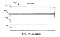
フォトレジストのさまざまな生成が知られる。遠紫外線(DUV)フォトレジストは、248nmの光によって露光される。理解をすすめるために、図1Aは、スタック100を形成する、エッチングされるべきレイヤ108上にあるARL(反射防止膜)110上にあるパターン付きフォトレジストレイヤ112を持つ基板104上のレイヤ108の概略断面図である。フォトレジストパターンは、微小寸法(CD)を有し、これは最も小さいフィーチャである幅116でありえる。現在、248nmフォトレジストについては、従来のプロセスを用いて、フォトレジストについての典型的なCDは230〜250nmでありえる。波長に依存する光学特性のために、より長い波長によって露光されるフォトレジストは、より大きい理論最小微小寸法を有する。
Various generations of photoresist are known. Deep ultraviolet (DUV) photoresist is exposed by 248 nm light. To facilitate understanding, FIG. 1A shows the
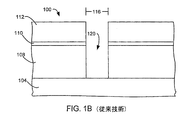
フィーチャ120は、図1Bに示されるようにフォトレジストパターンを通してそれからエッチングされえる。理想的には、フィーチャのCD(フィーチャの幅)は、フォトレジスト112におけるフィーチャのCD116に等しい。実際には、フィーチャ116のフィーチャのCDは、ファセッティング、フォトレジストのエロージョン、またはアンダーカッティングのためにフォトレジスト112のCDよりも大きいことがありえる。フィーチャは、テーパーが付けられることもありえ、ここでフィーチャのCDは、少なくともフォトレジストのCDと同じくらい大きいが、フィーチャはテーパーのためにフィーチャの底部近くではより小さい幅しか有しない。そのようなテーパリングは信頼性の低いフィーチャを提供しえる。
The
より小さいCDを持つフィーチャを提供するために、より短い波長光を用いて形成されたフィーチャが追求されている。193nmフォトレジストは、193nm光によって露光される。位相シフトレチクルおよび他の技術を用いて、193nmフォトレジストを用いて90〜100nmCDフォトレジストパターンが形成されえる。これは、90〜100nmのCDを持つフィーチャを提供することを可能にする。157nmフォトレジストは、157nm光によって露光される。位相シフトレチクルおよび他の技術を用いて、サブ90nmCDフォトレジストパターンが形成されえる。これは、サブ90nmのCDを持つフィーチャを提供することを可能にする。 In order to provide features with smaller CDs, features formed with shorter wavelength light have been pursued. The 193 nm photoresist is exposed by 193 nm light. Using phase shift reticles and other techniques, 90-100 nm CD photoresist patterns can be formed using 193 nm photoresist. This makes it possible to provide features with a CD of 90-100 nm. The 157 nm photoresist is exposed by 157 nm light. Sub-90 nm CD photoresist patterns can be formed using phase shift reticles and other techniques. This makes it possible to provide features with sub-90 nm CDs.
より短い波長のフォトレジストの使用は、より長い波長を用いたフォトレジストに対してさらなる問題を引き起こしえる。理論限界に近いCDを得るために、リソグラフィ装置は、より精密でなければならず、これはより高価なリソグラフィ機器を要求する。現在、193nmフォトレジストおよび157nmフォトレジストは、より長い波長のフォトレジストほど高い選択性を有していないかもしれず、プラズマエッチング条件においてより容易に変形するかもしれない。 The use of shorter wavelength photoresists can cause additional problems for photoresists with longer wavelengths. In order to obtain a CD that is close to the theoretical limit, the lithographic apparatus must be more precise, which requires a more expensive lithographic apparatus. Currently, 193 nm and 157 nm photoresists may not have as high selectivity as longer wavelength photoresists and may more easily deform in plasma etch conditions.
メモリデバイスの形成におけるような導電性レイヤのエッチングにおいては、パフォーマンスを下げることなくデバイス密度を高めることが望ましい。 In etching conductive layers, such as in the formation of memory devices, it is desirable to increase device density without reducing performance.
前述を達成するために、本発明の目的によれば、レイヤ中にフィーチャを形成する方法が提供される。前記レイヤ上にフォトレジストレイヤが形成される。前記フォトレジストレイヤをパターン付けすることによって、フォトレジスト側壁を持つフォトレジストフィーチャが形成され、前記フォトレジストフィーチャは第1微小寸法を有する。前記フォトレジストフィーチャの前記側壁上にコンフォーマルレイヤを堆積することによって、前記フォトレジストフィーチャの前記微小寸法が低減される。前記レイヤ内にフィーチャがエッチングされ、前記レイヤフィーチャは、前記第1微小寸法より小さい第2微小寸法を有する。 In order to achieve the foregoing, according to the objects of the present invention, a method of forming features in a layer is provided. A photoresist layer is formed on the layer. Patterning the photoresist layer forms a photoresist feature having photoresist sidewalls, the photoresist feature having a first micro dimension. By depositing a conformal layer on the sidewalls of the photoresist feature, the minor dimensions of the photoresist feature are reduced. A feature is etched in the layer, and the layer feature has a second minor dimension that is less than the first minor dimension.
本発明の他の実施形態において、レイヤ中にフィーチャを形成する方法が提供される。前記レイヤ上にフォトレジストレイヤが形成される。前記フォトレジストレイヤをパターン付けすることによって、フォトレジスト側壁を持つフォトレジストフィーチャが形成され、前記フォトレジストフィーチャは第1微小寸法を有する。前記フォトレジストフィーチャの前記側壁上にレイヤが堆積され、前記フォトレジストフィーチャの前記微小寸法が低減される。第1ガス化学物質での第1堆積によって第1堆積プラズマが形成され、第2ガス化学物質での第2堆積によって第2堆積プラズマが形成され、前記第1化学物質は前記第2化学物質と異なる。前記レイヤ内にフィーチャがエッチングされ、前記レイヤフィーチャは、第2微小寸法を有し、前記第2微小寸法は、前記第1微小寸法の70%より大きくない。 In another embodiment of the present invention, a method for forming features in a layer is provided. A photoresist layer is formed on the layer. Patterning the photoresist layer forms a photoresist feature having photoresist sidewalls, the photoresist feature having a first micro dimension. A layer is deposited on the sidewalls of the photoresist feature to reduce the minor dimensions of the photoresist feature. A first deposition plasma is formed by a first deposition with a first gas chemical, a second deposition plasma is formed by a second deposition with a second gas chemical, and the first chemical is coupled with the second chemical. Different. A feature is etched into the layer, the layer feature having a second micro dimension, wherein the second micro dimension is not greater than 70% of the first micro dimension.
本発明の他の実施形態においては、レイヤ中にフィーチャを形成する装置が提供され、前記レイヤは、基板によって支持され、前記レイヤは、第1CDを持つフォトレジストフィーチャを持つフォトレジストマスクによって覆われる。プラズマ処理チャンバは、プラズマ処理チャンバエンクロージャを形成するチャンバ壁、前記プラズマ処理チャンバエンクロージャ内で基板を支持する基板支持、前記プラズマ処理チャンバエンクロージャ内の圧力を制御する圧力レギュレータ、プラズマを維持するために前記プラズマ処理チャンバエンクロージャに電力を供給する少なくとも1つの電極、ガスを前記プラズマ処理チャンバエンクロージャ内に供給するガス吸気口、およびガスを前記プラズマ処理チャンバエンクロージャから排気するガス出口を備える。前記ガス吸気口と流体連通するガスソースは、第1堆積ガスソース、第2堆積ガスソース、およびエッチャントガスソースを備える。前記ガスソースおよび前記少なくとも1つの電極に制御可能に接続されたコントローラは、少なくとも1つのプロセッサ、およびコンピュータで読み取り可能な媒体を備える。前記コンピュータで読み取り可能な媒体は、前記フォトレジストフィーチャ内に、第2CDを持つフィーチャを形成するためにフォトレジストマスク上に側壁堆積を形成するよう少なくとも3つの堆積サイクルを行うコンピュータで読み取り可能なコード、前記少なくとも3つの堆積サイクルの完了後に、前記エッチャントガスソースから前記プラズマ処理チャンバへエッチャントガスのフローを供給するコンピュータで読み取り可能なコード、および前記エッチャントガスを用いて前記レイヤ中でフィーチャをエッチングするコンピュータで読み取り可能なコードであって、前記レイヤ中の前記フィーチャは第3CDを有するコードを備える。前記フォトレジストフィーチャ内に、第2CDを持つフィーチャを形成するためにフォトレジストマスク上に側壁堆積を形成するよう少なくとも3つの堆積サイクルを行うコンピュータで読み取り可能なコードは、前記第1堆積ガスソースから前記プラズマ処理チャンバエンクロージャへ第1堆積ガスのフローを供給するコンピュータで読み取り可能なコード、前記第1堆積ガスソースから前記プラズマ処理チャンバエンクロージャへの前記第1堆積ガスのフローを停止するコンピュータで読み取り可能なコード、前記第1堆積ガスの流れが停止された後で、前記第2堆積ガスソースから前記プラズマ処理チャンバエンクロージャへ第2堆積ガスのフローを供給するコンピュータで読み取り可能なコード、および前記第2堆積ガスソースから前記プラズマ処理チャンバエンクロージャへの前記第2堆積ガスのフローを停止するコンピュータで読み取り可能なコードを備える。 In another embodiment of the invention, an apparatus for forming features in a layer is provided, wherein the layer is supported by a substrate, and the layer is covered by a photoresist mask having a photoresist feature with a first CD. . A plasma processing chamber comprising: a chamber wall forming a plasma processing chamber enclosure; a substrate support for supporting a substrate within the plasma processing chamber enclosure; a pressure regulator for controlling the pressure within the plasma processing chamber enclosure; At least one electrode for supplying power to the plasma processing chamber enclosure, a gas inlet for supplying gas into the plasma processing chamber enclosure, and a gas outlet for exhausting gas from the plasma processing chamber enclosure. The gas source in fluid communication with the gas inlet includes a first deposition gas source, a second deposition gas source, and an etchant gas source. A controller controllably connected to the gas source and the at least one electrode comprises at least one processor and a computer readable medium. The computer readable medium is a computer readable code that performs at least three deposition cycles to form a sidewall deposition on the photoresist mask to form a feature with a second CD in the photoresist feature. Etch features in the layer using the etchant gas, and a computer readable code that supplies a flow of etchant gas from the etchant gas source to the plasma processing chamber after completion of the at least three deposition cycles Computer readable code, wherein the features in the layer comprise code having a third CD. A computer readable code for performing at least three deposition cycles to form a sidewall deposition on the photoresist mask to form a feature with a second CD in the photoresist feature is from the first deposition gas source. A computer readable code for supplying a flow of a first deposition gas to the plasma processing chamber enclosure; a computer readable code for stopping the flow of the first deposition gas from the first deposition gas source to the plasma processing chamber enclosure; A computer readable code for supplying a second deposition gas flow from the second deposition gas source to the plasma processing chamber enclosure after the flow of the first deposition gas is stopped, and the second From the deposition gas source It comprises computer readable code for stopping the serial flow of the second deposition gas to the plasma processing chamber enclosure.
本発明の他の実施形態においては、複数の導電性ラインを形成する方法が提供される。導電性レイヤが基板上に配置される。マスクが形成され、前記マスクは、前記マスクラインの間にマスク間隔を持つ複数のマスクラインを定義し、前記マスク間隔は幅を有し、前記マスクラインは幅および側壁を有する。マスクの前記側壁上にコンフォーマルレイヤが堆積される。マスクを通して前記導電性レイヤがエッチングされることによって、導電性ラインおよび前記導電性ライン間の間隔が形成され、前記導電性ラインは幅を有し、前記導電性ライン間の前記間隔は幅を有し、前記導電性ライン間の前記間隔の前記幅は、前記マスク間隔の前記幅より小さく、前記導電性ラインの前記幅は前記ラインマスクの前記幅より大きい。 In another embodiment of the present invention, a method for forming a plurality of conductive lines is provided. A conductive layer is disposed on the substrate. A mask is formed, wherein the mask defines a plurality of mask lines having a mask interval between the mask lines, the mask interval having a width, and the mask line having a width and a sidewall. A conformal layer is deposited on the sidewalls of the mask. The conductive layer is etched through a mask to form a conductive line and a gap between the conductive lines, the conductive line having a width, and the gap between the conductive lines having a width. The width of the gap between the conductive lines is smaller than the width of the mask gap, and the width of the conductive line is larger than the width of the line mask.
本発明のこれらおよび他の特徴は、本発明の詳細な説明において、添付の図を参照して以下により詳細に説明される。 These and other features of the present invention will be described in more detail below in the detailed description of the invention and with reference to the accompanying figures.
本発明は、添付図面の図中で限定によってではなく例示によって示され、同様の番号は同様の要素を示す。 The present invention is illustrated by way of example and not limitation in the figures of the accompanying drawings, wherein like numerals indicate like elements.
本発明は、添付の図面に示されるように、そのいくつかの好ましい実施形態を参照して詳細に説明される。以下の記載において、本発明の完全な理解を提供するために多くの具体的な詳細が述べられる。しかし当業者には、本発明はこれら具体的な詳細の一部または全てがなくても実施できることが明らかだろう。他の場合には、本発明の趣旨を不必要にぼかさないために、よく知られたプロセスステップおよび/または構成は詳細に記載されていない。 The invention will now be described in detail with reference to a few preferred embodiments thereof as illustrated in the accompanying drawings. In the following description, numerous specific details are set forth in order to provide a thorough understanding of the present invention. However, it will be apparent to one skilled in the art that the present invention may be practiced without some or all of these specific details. In other instances, well known process steps and / or configurations have not been described in detail in order not to unnecessarily obscure the spirit of the present invention.
本発明は、小さい微小寸法(CD)を持つフィーチャを提供する。より具体的には、本発明は、フィーチャをエッチングするのに用いられるフォトレジストパターンのCDより小さいCDを持つフィーチャを提供する。 The present invention provides features with small micro-dimensions (CD). More specifically, the present invention provides features having a CD that is smaller than the CD of the photoresist pattern used to etch the features.
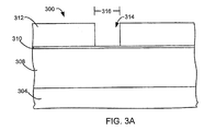
理解を進めるために、図2は、本発明の実施形態において用いられえるプロセスの高レベルフロー図である。パターン付きフォトレジストマスクが提供される(ステップ204)。図3Aは、スタック300を形成する、エッチングされるべきレイヤ308上にあるARL310上にあるフィーチャ314を持つパターン付きフォトレジストマスク312を持つ基板304上のエッチングされるべきレイヤ308の概略断面図である。フォトレジストマスクは、フォトレジストフィーチャ微小寸法(CD)を有し、これは最も小さい可能なフィーチャの幅316の最も広い部分でありえる。現在、248nmフォトレジストについては、フォトレジストの典型的なCDは、従来のプロセスを用いて230〜250nmでありえる。
For further understanding, FIG. 2 is a high level flow diagram of a process that may be used in embodiments of the present invention. A patterned photoresist mask is provided (step 204). FIG. 3A is a schematic cross-sectional view of a
CDを低減するために、それからレイヤがフォトレジストフィーチャの側壁上に堆積される(208)。図3Bは、フィーチャ314の側壁上に堆積されたレイヤ320を持つパターン付きフォトレジストマスク312の概略断面図である。堆積されたレイヤ320は、堆積されたレイヤフィーチャ322をフォトレジストフィーチャ314内に形成し、ここで堆積されたレイヤフィーチャ322は、フォトレジストフィーチャ314のCD316より小さい低減されたCD324を有する。好ましくは、堆積されたレイヤフィーチャ322の低減されたCD324は、フォトレジストフィーチャのCD316よりも少なくとも30%は小さい(すなわちフォトレジストフィーチャのCD316の70%より大きくはない)。より好ましくは、堆積されたレイヤフィーチャ322の低減されたCD324は、フォトレジストフィーチャのCD316よりも少なくとも40%は小さい(すなわちフォトレジストフィーチャのCD316の60%より大きくはない)。最も好ましくは、堆積されたレイヤフィーチャ322の低減されたCD324は、フォトレジストフィーチャのCD316よりも少なくとも50%は小さい(すなわちフォトレジストフィーチャのCD316の50%より大きくはない)。例えば、堆積されたレイヤフィーチャは、フォトレジストフィーチャのCD316より99%小さい低減されたCD316を有しえる。堆積されたレイヤフィーチャ322は、示されるように非常にコンフォーマルである、実質的に垂直な側壁328を有することも望ましい。実質的に垂直な側壁の例は、底部から上部で、フィーチャの底部に対して88°から90°の間の角を成す側壁である。コンフォーマルな側壁は、フィーチャの上部から底部まで実質的に同じ厚さを有する堆積レイヤを有する。非コンフォーマル側壁は、ファセッティング(faceting)またはブレッドロウフィング(bread-loafing)形状を形成しえ、これは実質的に垂直な側壁ではない。テーパーが付けられた側壁(ファセット形成から)またはブレッドロウフィング側壁は、堆積されたレイヤのCDを増し、低質なエッチングマスクを提供しえる。好ましくは、側壁上の堆積は、フォトレジストフィーチャの底部上の堆積よりも厚い。より好ましくは、フォトレジストフィーチャの底部上にはレイヤが堆積されない。
To reduce CD, a layer is then deposited on the sidewalls of the photoresist feature (208). FIG. 3B is a schematic cross-sectional view of a patterned
それからフィーチャは、エッチングされるべきレイヤ308内へと堆積されたレイヤフィーチャ322を通してエッチングされる(ステップ212)。図3Cは、エッチングされるべきレイヤ308内へとエッチングされたフィーチャ332を示す。この例では、エッチングされるべきレイヤ308内へとエッチングされたフィーチャ332は、CD336を有し、これは堆積されたレイヤフィーチャ322のCD324に等しい。実際にはあ、フィーチャ332のCD336は、堆積されたレイヤ320のフィーチャ322のCD324よりわずかに大きいかもしれない。しかし、堆積されたレイヤフィーチャ322のCD324は、フォトレジスト312のCD316より大幅に小さいので、エッチングされるべきレイヤ308内のフィーチャ332のCD336は、依然としてフォトレジスト312のCD316よりも小さい。もし堆積されたレイヤのCD324がフォトレジストのCDよりわずかに小さいなら、またはもし堆積されたレイヤにファセットが付けられ、またはブレッドロウフが付けられたなら、エッチングされるべきレイヤのCDは、フォトレジストのCDより小さくないかもしれない。加えて、ファセットまたはブレッドロウフが付けられた堆積されたレイヤは、ファセット付きまたは不規則な形状のフィーチャをエッチングされるべきレイヤ内に生じえる。フォトレジストフィーチャの底部上の堆積を最小化することも望ましい。好ましくは、エッチングされるべきレイヤ308内にエッチングされたフィーチャ332のCD336は、フォトレジストフィーチャのCD316よりも少なくとも30%小さい。より好ましくは、エッチングされるべきレイヤ308内にエッチングされたフィーチャ332のCD336は、フォトレジストフィーチャのCD316よりも少なくとも40%小さい。最も好ましくは、エッチングされるべきレイヤ308内にエッチングされたフィーチャ332のCD336は、フォトレジストフィーチャのCD316よりも少なくとも50%小さい。
The features are then etched through the layer features 322 deposited into the
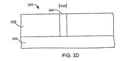
フォトレジストおよび堆積されたレイヤは、それから剥離されえる(ステップ216)。これは単一のステップまたは別個の堆積レイヤ除去ステップおよびフォトレジスト剥離ステップを持つ2つの別個のステップとしてなされえる。アッシングが剥離プロセスのために用いられえる。図3Dは、堆積されたレイヤおよびフォトレジストマスクが除去された後のスタック300を示す。追加の形成ステップが実行されえる(ステップ220)。例えば、コンタクト340がフィーチャ中に形成されえる。デュアルダマシン構造を提供するために、コンタクトが形成される前にトレンチがエッチングされえる。追加のプロセスがコンタクトが形成された後に実行されえる。
The photoresist and deposited layer can then be stripped (step 216). This can be done as a single step or as two separate steps with separate deposited layer removal and photoresist stripping steps. Ashing can be used for the stripping process. FIG. 3D shows the
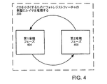
図4は、フォトレジストフィーチャの側壁上にレイヤを堆積してCDを減らすステップ208のより詳細なフロー図である。この実施形態においては、フォトレジストフィーチャの側壁上にレイヤを堆積してCDを低減するステップ208は、第1堆積フェーズ404および第2堆積フェーズ408を備える。
FIG. 4 is a more detailed flow diagram of
誘電体エッチングの例Dielectric etching example
図5は、レイヤを堆積し、エッチングし、および剥離するのに用いられえるプラズマ処理チャンバ500の概略図である。プラズマ処理チャンバ500は、閉じ込めリング502、上部電極504、下部電極508、ガスソース510、および排気ポンプ520を備える。ガスソース510は、第1堆積ガスソース512および第2堆積ガスソース516を備える。ガスソース510は、エッチングガスソース518のような追加のガスソースを備えうる。プラズマ処理チャンバ500内では、基板304は下部電極508上に配置される。下部電極508は、基板304を保持する適切な基板チャッキングメカニズム(例えば静電、機械クランピングのような)を組み込む。リアクタトップ528は、下部電極508に直接に対向するよう配置される上部電極504を組み込む。上部電極504、下部電極508、および閉じ込めリング502は、閉じ込めプラズマ容積を定義する。ガスがガスソース510によって閉じ込めプラズマ容積に供給され、排気ポンプ520によって閉じ込めリング502および排気口を通して閉じ込めプラズマ容積から排気される。第1RFソース544は、上部電極504に電気的に接続される。第2RFソース548は、下部電極508に電気的に接続される。チャンバ壁552は、閉じ込めリング502、上部電極504、および下部電極508を囲む。第1RFソース544および第2RFソース548は、27MHz電力源および2MHz電力源を備えうる。RF電力を電極に接続する異なる組み合わせが可能である。カリフォルニア州、FremontのLAM Research Corporation≡によって作られた、チャンバに取り付けられたTurbo Pumpを持つExelan HPと基本的に同じである、Exelan HPT≡は、本発明の好ましい実施形態において用いられえ、ここで27MHzおよび2MHzの両方の電力源が、下部電極に接続された第2RF電力ソース548を構成し、上部電極は接地される。コントローラ535は、RFソース544、548、排気ポンプ520、およびガスソース510に制御可能に接続される。エッチングされるべきレイヤ308がシリコン酸化物または有機珪酸塩ガラスのような誘電体レイヤであるときには、Exelan HPTが用いられえる。
FIG. 5 is a schematic diagram of a
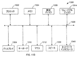
図11Aおよび11Bは、本発明の実施形態において用いられるコントローラ535を実現するのに適したコンピュータシステム1300を示す。図11Aは、このコンピュータシステムの一つの可能な物理的形態を示す。もちろんコンピュータシステムは、集積回路、プリント基板、および小型携帯機器から、大型のスーパーコンピュータに至るまで多くの物理的形態をとりえる。コンピュータシステム1300は、モニタ1302、ディスプレイ1304、筐体1306、ディスクドライブ1308、キーボード1310、およびマウス1312を含む。ディスク1314は、データをコンピュータシステム1300に転送し、かつデータをコンピュータシステム1300から転送するために用いられるコンピュータ読み取り可能な媒体である。
FIGS. 11A and 11B illustrate a
図11Bは、コンピュータ1300のブロック図の例である。システムバス1320に接続されているのは、さまざまなサブシステムである。プロセッサ(群)1322(中央処理装置、すなわちCPUとも呼ばれる)は、メモリ1324を含む記憶装置に結合されている。メモリ1324は、ランダムアクセスメモリ(RAM)および読み出し専用メモリ(ROM)を含む。この技術ではよく知られるようにROMは、データおよび命令を単一方向にCPUおよびRAMに転送するようにはたらき、RAMは、典型的にはデータおよび命令を双方向に転送するのに用いられる。メモリのこれら両方のタイプは、以下に述べるコンピュータ読み出し可能な適当な媒体を含みえる。固定ディスク1326はまた、双方向でCPU1322に結合され、追加のデータ記憶容量を提供し、また以下に述べるコンピュータ読み出し可能な適当な媒体を含みえる。固定ディスク1326は、プログラム、データなどを記憶するのに用いられえて、典型的には一次記憶よりも低速な二次記憶媒体(ハードディスクのような)である。固定ディスク1326内に保持された情報は、適切な場合においては、メモリ1324の仮想メモリとして標準的なかたちで統合されえることが理解されよう。取り外し可能なディスク1314は、以下に説明するコンピュータ読み出し可能な媒体のいかなる形態をも取りえる。
FIG. 11B is an example of a block diagram of the
CPU1322はまた、ディスプレイ1304、キーボード1310、マウス1312およびスピーカ1330のようなさまざまな入力/出力装置に結合される。一般に入力/出力装置は、ビデオディスプレイ、トラックボール、マウス、キーボード、マイク、タッチパネルディスプレイ、トランスデューサカードリーダ、磁気または紙テープリーダ、タブレット、スタイラス、音声または手書き認識機、生体情報読み取り機、または他のコンピュータのいずれでもよい。CPU1322は追加で、ネットワークインタフェース1340を用いて他のコンピュータまたは通信ネットワークに結合されてもよい。そのようなネットワークインタフェースによりCPUは、上述の方法ステップを実行する過程で、ネットワークから情報を受け取り、または情報をネットワークに出力してもよい。さらに本発明の方法の実施形態は、CPU1322上だけで実行されてもよく、またはインターネットのようなネットワーク上で、処理の一部を担当する遠隔地にあるCPUと協働して実行されてもよい。
The
さらに本発明の実施形態は、コンピュータによって実現できるさまざまな操作を実行するコンピュータコードを格納した、コンピュータによって読み出し可能な媒体を持つコンピュータ記憶製品に関する。媒体およびコンピュータコードは、本発明の目的のために特別に設計され構築されたものでもよく、またはコンピュータソフトウェア技術の当業者に既知の利用可能なものであってもよい。コンピュータ読み出し可能な媒体の例としては、これらに限定はされないが、ハードディスク、フレキシブルディスク、および磁気テープのような磁気媒体、CD−ROMおよびDVDおよびホログラフィックデバイスのような光媒体、フロプティカルディスクのような光磁気媒体、特定アプリケーション向け集積回路(ASIC)、プログラム可能な論理デバイス(PLD)、およびROMおよびRAMデバイスのように、プログラムコードを記憶し実行するために特別に構成されたハードウェアデバイスが挙げられる。コンピュータコードの例としては、コンパイラによって生成される機械語、およびインタープリタを用いてコンピュータによって実行可能なより高いレベルのコードを含むファイルが挙げられる。コンピュータで読み取り可能な媒体は、搬送波中で実現される、プロセッサによって実行される一連の命令を表すコンピュータデータ信号によって搬送されるコンピュータコードでありえる。 Embodiments of the present invention further relate to a computer storage product having a computer readable medium storing computer code for performing various computer-implemented operations. The media and computer code may be specially designed and constructed for the purposes of the present invention, or may be available known to those skilled in the computer software art. Examples of computer readable media include, but are not limited to, magnetic media such as hard disks, flexible disks, and magnetic tapes, optical media such as CD-ROM and DVD and holographic devices, and floppy disks. Hardware specifically configured to store and execute program code, such as magneto-optical media, application specific integrated circuits (ASICs), programmable logic devices (PLDs), and ROM and RAM devices Device. Examples of computer code include machine language generated by a compiler and files containing higher level code that can be executed by a computer using an interpreter. The computer readable medium can be computer code carried in a carrier wave by computer data signals representing a series of instructions executed by a processor.
他の例においては他の堆積装置が用いられえる。 In other examples, other deposition devices can be used.
第1堆積フェーズ404の一例は、250sccm(標準立方センチメートル毎分)のArおよび50sccmのCH3Fである化学物質を用いた圧力60mTorrにおけるターボポンプのVatバルブを1000に設定することによって確立されるCH3F堆積でありえる。27MHzRFソースは、500ワットの電力を供給し、一方、2MHzのRFソースは、100ワットの電力を供給する。チャンバ温度は20℃に維持される。基板を冷やすためのヘリウム冷却圧力は15Torrである。
An example of the
第2堆積フェーズ408の一例は、270sccmのAr、12sccmのC4F6、8sccmのO2、および100sccmのCOである化学物質を用いた圧力50mTorrにおけるターボポンプのVatバルブを1000に設定することによって確立されるC4F6/O2/CO堆積でありえる。27MHzRFソースは、1500ワットの電力を供給し、一方、2MHzのRFソースは、480ワットの電力を供給する。チャンバ温度は20℃に維持される。基板を冷やすためのヘリウム冷却圧力は15Torrである。
An example of the
図6は、堆積レイヤ620の概略断面図であり、ここで第1堆積フェーズの堆積しか堆積レイヤ620の全体に用いられていない。堆積レイヤ620は、フォトレジストマスク612の上に形成され、それはARL610の上にあり、それはエッチングされるべきレイヤ608の上にあり、それは基板604の上にある。フォトレジストマスク612はフィーチャ614を形成する。この例では、第1堆積は、「ブレッドロウフ」堆積レイヤを形成する。ブレッドロウフ堆積レイヤは、フィーチャの上部付近でのより厚い側壁堆積632およびフィーチャの底部付近でのより薄い(またはまったくない)側壁堆積636によって特徴付けられる。したがって、この堆積は、非コンフォーマル側壁堆積を提供する。そのような堆積は、所望の実質的に垂直な側壁を提供しない。ブレッドロウフは、最終的には上部をくびれ切り、これはそれからマスキングレイヤとしては使えないが、これはコンタクトが閉じられてしまいそれ以上のエッチングがなされえないからである。
FIG. 6 is a schematic cross-sectional view of the
図7は、堆積レイヤ720の概略断面図であり、ここでは第2堆積フェーズの堆積しか堆積レイヤ720の全体に用いられていない。堆積レイヤ720は、フォトレジストマスク712の上に形成され、それはARL710の上にあり、それはエッチングされるべきレイヤ708の上にあり、それは基板704の上にある。フォトレジストマスク712はフィーチャ714を形成する。この例では、第1堆積は、「ファセッティング」堆積レイヤを形成する。このファセッティング堆積レイヤは、フィーチャの上部付近でのより薄い(またはまったくない)側壁堆積732およびフィーチャの底部付近でのより厚い側壁堆積736によって特徴付けられる。したがって、この堆積も非コンフォーマル側壁堆積を提供する。もし上部付近の側壁が薄すぎるなら、フォトレジストマスク712のファセッティング740が生じる。そのような堆積は、所望の実質的に垂直な側壁を提供しない。フォトレジストマスクの角のファセッティングは、より低いエッチング選択性および速いマスクエロージョンを生じえる。マスクのファセッティングは、エッチングされたプロファイルのファセッティングにもつながる。ほとんど全ての場合において、いったんマスクにファセットが付けられると、最終的なエッチングされたプロファイルもファセットが付けられるが、これは、マスクの垂直プロファイルが一般にはエッチングされた材料に移されるからである。
FIG. 7 is a schematic cross-sectional view of the
したがって、本発明の好ましい実施形態の例においては、上の例での第1堆積フェーズ404および第2堆積フェーズ408は、6サイクル交互に繰り返され、ここで第1堆積フェーズ404は2秒であり、第2堆積フェーズ408は25秒である。このような堆積は、第1堆積フェーズ404の第1堆積、およびそれから第2堆積フェーズ408の第2堆積、それから第1堆積フェーズ404の第3堆積、それから第2堆積フェーズ408の第4堆積を有し、これは第12堆積ができるまで繰り返される。
Thus, in the preferred embodiment example of the present invention, the
図8は、248nmフォトレジストを用いたフォトレジストエッチングマスク804の上面図である。フォトレジストエッチングマスク804は、複数のフォトレジストフィーチャ808を有する。この例では、フォトレジストフィーチャ808は206nmのCD812を有する。この例では、CD812はフォトレジストフィーチャの直径である。
FIG. 8 is a top view of a
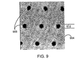
図9は、上述の例を用いてフォトレジストエッチングマスク上に堆積された堆積レイヤ904の上面図である。堆積レイヤ904は、複数のフォトレジストフィーチャの中に位置する複数のフィーチャ908を有する。フィーチャ908は、この例では115nmであると計測されたCD912を有し、これはフォトレジストフィーチャのCD812の56%であり、よって堆積されたレイヤフィーチャのCD912は、フォトレジストフィーチャのCD812より44%小さい。この例では、CDはフィーチャの直径である。
FIG. 9 is a top view of a
図10は、堆積レイヤ1008で覆われたフォトレジストマスク1004中のフィーチャ1002の断面図である。示されるように、フィーチャ1002は、実質的に垂直な側壁1010を有し、よってフィーチャの幅はフィーチャ1002の長さに沿って実質的に同じである。加えて、側壁上のレイヤは非常にコンフォーマル(conformal)であり、よってレイヤは、フィーチャの上部から底部まで均質な厚さを有する。
FIG. 10 is a cross-sectional view of a
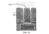
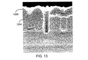
図12は、248nmフォトレジストを用いて形成されたフォトレジストマスク1204におけるフィーチャ1202の断面図である。この例では、フォトレジストフィーチャは250nmのCDを有する。2フェーズ堆積が用いられて、フォトレジストマスク1204の側壁上に堆積レイヤを提供する。2フェーズ堆積は、前の例とは異なるレシピを用いえる。図13は、堆積レイヤ1208で覆われたフォトレジストマスク1204中のフィーチャ1202の断面図である。堆積レイヤ1208中のフィーチャのCDは140nmである。堆積レイヤ1208中のフィーチャは、フォトレジストの下のレイヤをエッチングするのに用いられる。図14は、堆積レイヤおよびフォトレジストレイヤが剥離された後に、堆積レイヤ中のフィーチャを通してフォトレジストの下でレイヤ1408内にエッチングされたフィーチャ1404の断面図である。フィーチャ1404のCDは140nmである。
FIG. 12 is a cross-sectional view of
第1堆積フェーズ404および第2堆積フェーズ408のエッチング時間の比を制御できる能力は他の制御変数を提供する。適切な比は、図3Bに示されるような実質的に垂直でコンフォーマルな側壁を提供する。そのような堆積レイヤは、フォトレジストマスクを保護し、エッチング選択性を高めることができる。堆積プロファイルを制御するのに用いられえる本発明による他の制御パラメータは、サイクル数、総体積時間、堆積1/堆積2の時間比、ガス化学物質比(例えばCH3F/O2比またはC4F6/O2比)である。CH3Fの代わりにCH2F2、またはC4F6の代わりにC4F8のような他のガス化学物質も用いられえる。
The ability to control the etch time ratio of the
フォトレジストを変えることなく、より小さい微小寸法を持つフィーチャを形成できる能力は、新しいリソグラフィ機器を購入することなく、より小さいフィーチャを可能にする。フォトレジストのより新しい世代が用いられ、本発明は、フォトレジストの新しい世代のための小さいCDを提供する。 The ability to form features with smaller dimensions without changing the photoresist allows for smaller features without purchasing new lithographic equipment. Newer generations of photoresist are used, and the present invention provides a small CD for the new generation of photoresist.
他の実施形態において、3つ以上の異なる堆積フェーズを提供する3つ以上の異なるガス化学物質が用いられえる。 In other embodiments, more than two different gas chemistries that provide more than two different deposition phases may be used.
導電性レイヤエッチングの例Example of conductive layer etching
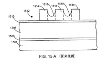
金属コネクタまたはフラッシュメモリのようなメモリデバイスのような導電性ラインの形成においては、導電性ラインの厚さを増し、および/または導電性ラインの間の間隔のCDを減らすことが望ましい。図15Aは、導電性ラインのためのフォトレジストマスクの断面図であり、従来技術によるライン間の間隔が狭すぎる場合である。ウェーハのような基板1504上にはバリア層1506が置かれえる。バリア層1506上には、金属レイヤまたはポリシリコンレイヤのような導電性レイヤ1508が形成される。導電性レイヤ1508上には、DARCレイヤのような反射防止膜(ARL)1510が形成される。フォトレジストマスク1512はARL1510上に形成される。この例では、フォトレジストマスク1512は、ラインマスク1514の間の空間中に形成されたフォトレジスト残渣1518を持つラインマスク1514を形成する。フォトレジスト残渣1518の存在は、ラインマスク1514間に狭すぎる間隔を提供することによって引き起こされるが、これは小さい空間から残渣を除去することがより困難だからである。これは、提供されえる導電性ラインの密度を制限しえる。
In the formation of conductive lines such as metal connectors or memory devices such as flash memory, it is desirable to increase the thickness of the conductive lines and / or reduce the CD of the spacing between the conductive lines. FIG. 15A is a cross-sectional view of a photoresist mask for conductive lines, where the spacing between lines according to the prior art is too narrow. A
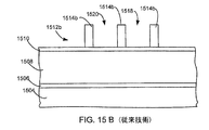
図15Bは、狭すぎる間隔によって生じる問題を克服しようと従来技術において用いられる、導電性ラインを作るためのフォトレジストマスク1512bの他の断面図である。この例におけるラインマスク1514bは、より広い間隔1520を可能にしてレジスト残渣を防ぎ、前の例と同じピッチつまり密度を維持するために、より細くされる。このアプローチの欠点のうちの1つは、より細いラインマスク1514bはより細いラインにつながることである。より細いラインは、信頼性が落ち、パフォーマンスも下がることにつながりえる。より細いラインは、より小さいトランジスタ領域につながりえ、これはショートチャネル効果およびショートチャネル効果および高ワードライン抵抗(速度低下を引き起こす)のような他のパフォーマンス上の問題を生じえる。
FIG. 15B is another cross-sectional view of a
図15Cは、狭すぎる間隔によって生じる問題を克服しようと従来技術において用いられる、導電性ラインを作るためのフォトレジストマスク1512cの他の断面図である。ある応用例においては、ラインマスク1514cが間隔1522と同じ幅を有するのが望ましい。この例ではレジスト残渣を防ぐために間隔1522はより広く作られているので、ラインマスク1514cもより広い。その結果、ピッチは広がり、ラインの密度は減る。
FIG. 15C is another cross-sectional view of a
より広いライン幅を維持しつつ、ライン間の間隔を減らすことによって、より密に配置された導電性ラインを提供することが望ましい。 It would be desirable to provide more closely spaced conductive lines by reducing the spacing between the lines while maintaining a wider line width.
図2に示される高レベルプロセスは、本発明のこの実施形態の理解をすすめるために用いられる。パターン付きフォトレジストマスクが提供される(ステップ204)。図16Aは、基板1604の上のバリア層1606の上にあるエッチングされるべき導電性レイヤ1608の概略断面図であり、これはマスクライン1614を形成するパターン付きフォトレジストマスク1612を持ち、その間にはマスクスペース1620を持ち、それらはARL1610の上にあり、それはエッチングされるべき導電性レイヤ1608の上にある。フォトレジストマスクは、間隔の幅1616である間隔微小寸法(CD)、およびマスクライン1614の幅1626であるラインCDを有する。現在、248nmフォトレジストについては、間隔幅CDについての典型的なCDは、0.16μmである。一般に、フォトレジスト中の間隔の幅は、そのスペース中にフォトレジストの残渣がないようにフォトレジスト中にスペースを形成するように充分に広く作られる。フォトレジストマスクラインの幅は、導電性ラインの密度が増されるように充分に細く作られる。
The high level process shown in FIG. 2 is used to promote an understanding of this embodiment of the invention. A patterned photoresist mask is provided (step 204). FIG. 16A is a schematic cross-sectional view of a
それから間隔の幅を減らすために、フォトレジストフィーチャの側壁上にコンフォーマルレイヤが堆積される(ステップ208)。図16Bは、マスク1612の側壁上に堆積されたレイヤ1630を持つパターン付きフォトレジストマスク1612の概略断面図である。堆積されたレイヤ1630は、マスクスペース内に堆積されたレイヤ間隔1632を形成し、ここで堆積されたレイヤスペース1632は、マスクスペースの幅1616より小さい低減された幅(CD)1634を有する。加えて、堆積されたレイヤ1630は、マスクライン1614の幅1626より大きい幅1638を持つ堆積されたレイヤマスクラインを形成する。好ましくは、堆積されたレイヤスペース1632の低減された幅1634は、マスクスペース1620の幅1616より少なくとも20%少ない(すなわちマスクスペース1620の幅1616の80%より大きくない)。より好ましくは、堆積されたレイヤスペース1632の低減された幅1634は、マスクスペース1620の幅1616より少なくとも50%少ない(すなわちマスクスペース1620の幅1616の50%より大きくない)。最も好ましくは、堆積されたレイヤスペース1632の低減された幅1634は、マスクスペース1620の幅1616より少なくとも70%少ない(すなわちマスクスペース1620の幅1616の30%より大きくない)。堆積されたレイヤは実質的に垂直な側壁1642を形成し、これが示されるように非常にコンフォーマルである(conformal)ことも望ましい。実質的に垂直な側壁の一例は、底部から上部で、スペースの底部に対して88°から90°の間の角を成す側壁である。コンフォーマルな側壁は、スペースの上部から底部まで実質的に同じ厚さを有する堆積レイヤを有する。導電性レイヤエッチングのためのこのプロセスは、単一の堆積でコンフォーマルなレイヤを提供することができる。
A conformal layer is then deposited on the sidewalls of the photoresist feature to reduce the spacing width (step 208). FIG. 16B is a schematic cross-sectional view of a patterned
導電性レイヤをエッチングする好ましい実施形態において、堆積レイヤは、全ての向きにおいてコンフォーマルである(等方性)。この結果、ARL1610上のレイヤがマスクの側壁上のレイヤとほぼ同じ厚さになる。
In a preferred embodiment for etching the conductive layer, the deposition layer is conformal in all orientations (isotropic). As a result, the layer on
導電性レイヤ1608は、堆積レイヤ1630を通してエッチングされえる(ステップ212)。この例では、エッチングステップは、図17に示されるように少なくとも2つの別個のエッチングを備える。非等方性堆積レイヤエッチングは、堆積レイヤ1630をエッチングするために用いられる(ステップ1704)。図16Cは、堆積されたレイヤが非等方性的にエッチングされた後の基板の断面図である。残っている堆積されたレイヤは、マスクライン1614の周りに側壁1642を形成する。非等方性導電性レイヤエッチングは、導電性レイヤ1608の中へエッチングするのに用いられる(ステップ1708)。図16Dは、導電性レイヤがエッチングされて、その間に間隔1650を持つ導電性ライン1646を形成した後の基板の断面図である。図16Dに示されるように、導電性ライン1646は幅1648を有し、導電性ライン間の間隔は幅1652を有する。好ましくは、導電性ラインの間の間隔1650の幅1652は、マスクライン間の間隔1620の幅1616より少なくとも20%小さい。より好ましくは、導電性ラインの間の間隔1650の幅1652は、マスクライン間の間隔1620の幅1616より少なくとも50%小さい。最も好ましくは、導電性ラインの間の間隔1650の幅1652は、マスクライン間の間隔1620の幅1616より少なくとも70%小さい。
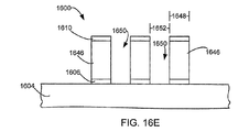
フォトレジストおよび堆積されたレイヤはそれから剥離される(ステップ216)。これは、単一のステップまたは別個の堆積されたレイヤを除去するステップおよびフォトレジスト剥離ステップを持つ2つの別個のステップとしてなされえる。アッシングが剥離プロセスのために用いられえる。図16Eは、堆積されたレイヤおよびフォトレジストマスクが除去された後のスタック1600を示す。追加のプロセスが実行されえる(ステップ220)。例えば、導電性ラインは、メモリデバイスの一部になるよう形成されえる。
The photoresist and deposited layer are then stripped (step 216). This can be done as a single step or as two separate steps with a separate deposited layer removal and a photoresist strip step. Ashing can be used for the stripping process. FIG. 16E shows the
結果として生じる構造は、より少ない間隔およびより広い導電性ラインを持つより高い密度のデバイスを提供する。この例では、導電性ライン1646の幅1648は、間隔1650の幅1652にほぼ等しい。他の間隔幅に対する導電性ラインの比がこの実施形態によって提供されえる。好ましくは、マスクラインの間の間隔の幅に対するマスクラインの幅の比は、1:1より小さく、ここで導電性ラインの間の間隔に対する導電性ラインの幅の比は1:1より小さくはなく、むしろ好ましくは1:1より大きい。そのような比は、より高い密度のメモリデバイスを提供するのに有用でありえ、ここで導電性レイヤはポリシリコンである。
The resulting structure provides a higher density device with less spacing and wider conductive lines. In this example, the
本発明の他の実施形態においては、マスクラインは、間隔の幅とほぼ等しい幅を有する。図18Aは、基板1804の上のバリア層1806の上にあるエッチングされるべき導電性レイヤ1808の概略断面図であり、これはマスクライン1814を形成するパターン付きフォトレジストマスク1812を持ち、その間にはマスクスペース1820を持ち、それらはARL1810の上にあり、それはエッチングされるべき導電性レイヤ1808の上にある。フォトレジストマスクは、間隔の幅1816である間隔微小寸法(CD)、およびマスクライン1814の幅1826であるラインCDを有する。一般に、フォトレジスト中の間隔の幅は、そのスペース中にフォトレジストの残渣がないようにフォトレジスト中にスペースを形成するように充分に広く作られる。
In another embodiment of the present invention, the mask lines have a width that is approximately equal to the width of the spacing. FIG. 18A is a schematic cross-sectional view of a
それから間隔の幅を減らすために、フォトレジストフィーチャの側壁上にコンフォーマルレイヤが堆積される(ステップ208)。図18Bは、マスク1812の側壁上に堆積されたレイヤ1830を持つパターン付きフォトレジストマスク1812の概略断面図である。堆積されたレイヤ1830は、マスクスペース内に堆積されたレイヤ間隔1832を形成し、ここで堆積されたレイヤスペース1832は、マスクスペースの幅1816より小さい低減された幅(CD)1834を有する。加えて、堆積されたレイヤ1830は、マスクライン1814の幅1826より大きい幅1838を持つ堆積されたレイヤマスクラインを形成する。
A conformal layer is then deposited on the sidewalls of the photoresist feature to reduce the spacing width (step 208). FIG. 18B is a schematic cross-sectional view of a patterned
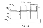
導電性レイヤ1808は、堆積レイヤ1830を通してエッチングされえる(ステップ212)。図18Cは、導電性レイヤがエッチングされて、その間に間隔1850を持つ導電性ライン1846を形成した後の基板の断面図である。図18Cに示されるように、導電性ライン1846は幅1848を有し、導電性ライン間の間隔は幅1852を有する。
フォトレジストおよび堆積されたレイヤはそれから剥離される(ステップ216)。図18Dは、堆積されたレイヤおよびフォトレジストマスクが除去された後のスタック1800を示す。追加のプロセスが実行されえる(ステップ220)。例えば、金属ラインは、さまざまなデバイスを電気的に接続するのに用いられえる。
The photoresist and deposited layer are then stripped (step 216). FIG. 18D shows the
結果として生じる構造は、より密に間隔が置かれたより広い導電性ワイヤを提供する。この例では、導電性金属ラインは、前になされたのと同じ密度を有しえるが、より小さい間隔を持つより広い導電性ラインを提供することは、低減された抵抗を提供することによるように、導電性ラインのパフォーマンスを改善する。本発明は、オリジナルのマスクのライン幅よりも100%より大きい分、広い導電性ライン幅を提供しえる。より好ましくは、導電性ライン幅はオリジナルのマスクのライン幅より150%より大きい分、広い。この実施形態において、堆積ステップは順番になされ、同時ではない。 The resulting structure provides a wider conductive wire that is more closely spaced. In this example, the conductive metal lines can have the same density as previously done, but providing a wider conductive line with smaller spacing is likely due to providing a reduced resistance. And improve the performance of the conductive line. The present invention can provide a wider conductive line width by 100% than the line width of the original mask. More preferably, the conductive line width is wider by 150% than the line width of the original mask. In this embodiment, the deposition steps are made in order and not simultaneously.
例示的レシピ Example recipe
例示的レシピにおいて、堆積レイヤおよび導電性レイヤを堆積およびエッチングするのに用いられえるデバイスは、カリフォルニア州、FremontのLAM Research Corporation≡によって作られる2300 Versys≡である。図19は、堆積レイヤを堆積およびエッチングの両方に用いられるそのような装置1900の概略図である。プラズマ処理チャンバ1900は、誘導性アンテナ(またはコイル)1902、ガス分配板(GDP)1904、基板支持1908、ガスソース1910、および排気ポンプ1920を備える。ガスソース1910は、ガス分配板1904と流体連通し、堆積ガスソース1912およびエッチングガスソース1916を備える。ガスソース1910は、第2エッチングまたは堆積ガスソースのような追加のガスソースを備えうる。プラズマ処理チャンバ1900内では、基板1604は基板支持1908上に配置される。基板支持1908は、基板1604を支持する適切な基板チャッキングメカニズム(例えば静電、機械クランピングなど)を組み込む。リアクタトップ1928は水晶誘電体窓1976を組み込み、これはアンテナ1902からチャンバ内へのエネルギーの伝送を可能にする。誘電体窓1976、基板支持1908、および陽極処理アルミニウムチャンバ壁1952は閉じ込めプラズマ容積を定義する。ガスは、ガスソース1910によって閉じ込めプラズマ容積に供給され、排気ポンプ1920によって排気口を通して閉じ込めプラズマ容積から排気される。第1RFソース1944は、電気的にアンテナに接続される。第2RFソース1948は、電気的に基板支持1908に接続される。この例では、第1RFソース1944は、13.56MHzの周波数を持つ信号を供給し、第2RFソース1948は、13.56MHzの周波数を持つ信号を供給する。
In an exemplary recipe, a device that can be used to deposit and etch the deposited and conductive layers is a 2300 Versys≡ made by LAM Research Corporation≡, Fremont, California. FIG. 19 is a schematic diagram of such an apparatus 1900 in which a deposition layer is used for both deposition and etching. The plasma processing chamber 1900 includes an inductive antenna (or coil) 1902, a gas distribution plate (GDP) 1904, a
堆積レイヤの堆積のあいだ(ステップ208)、10mTorrの圧力がチャンバに供給される。第1RFソース1944は、1000ワット(TCPパワー)をアンテナ1902によって誘電体窓1976を通してプラズマ容積1940に供給する。基板支持1908にはバイアスパワーは供給されない。堆積ガスソース1912は、50sccmのSiCl4および100sccmのO2のフローを15秒の堆積のあいだ供給する。これは、1,000〜2,000Åの厚さのSiClxOyのレイヤを形成する。このような膜は、酸化物膜でありえ、これはエッチングに耐えるだけ充分に強い。
During deposition layer deposition (step 208), a pressure of 10 mTorr is supplied to the chamber. The
堆積レイヤの非等方性エッチング(ステップ1704)のあいだ、5mTorrの圧力がチャンバに供給される。第1RFソース1994は、500ワットをアンテナ1902によってプラズマ容積1940に供給する。ー175ボルトのバイアスが基板支持に供給され、エッチングを促進するために陽イオンを基板へと加速する。エッチングガスソース1916は100sccmのCF4を供給する。
During the anisotropic etching of the deposition layer (step 1704), a pressure of 5 mTorr is supplied to the chamber. The first RF source 1994 supplies 500 watts to the
導電性レイヤの非等方性エッチング(ステップ1708)は、4つのエッチング、すなわちBT(ブレークスルー)エッチング、ME1(メインエッチング1)、ME2(メインエッチング2)、およびOE(オーバーエッチング)を用いて達成される。BTについては5mTorrの圧力が供給される。500ワットがアンテナ1902によってチャンバ1900に供給される。ー175ボルトのバイアスが基板支持1908に供給され、エッチングを促進するために陽イオンを基板へと加速する。エッチングソースは、100sccmのCF4を約10秒供給する。
The anisotropic etching of the conductive layer (step 1708) uses four etchings: BT (breakthrough) etching, ME1 (main etching 1), ME2 (main etching 2), and OE (overetching). Achieved. For BT, a pressure of 5 mTorr is supplied. 500 Watts are supplied to chamber 1900 by
ME1については、10mTorrの圧力が供給される。800ワットがアンテナ1902によってチャンバ1900に供給される。ー90ボルトのバイアスが基板支持1908に供給され、エッチングを促進するために陽イオンを基板へと加速する。エッチングソースは、100sccmのCl2を、100sccmのHBr、および5sccmのO2を約45秒供給する。
For ME1, a pressure of 10 mTorr is supplied. 800 Watts are supplied to chamber 1900 by
ME2については、20mTorrの圧力が供給される。400ワットがアンテナ1902によってチャンバ1900に供給される。ー170ボルトのバイアスが基板支持1908に供給され、エッチングを促進するために陽イオンを基板へと加速する。エッチングソースは、20sccmのCl2を、360sccmのHBr、および5sccmのO2を供給する。このエッチングをいつ止めるかを決定するためにエンドポイント検出が用いられる。
For ME2, a pressure of 20 mTorr is supplied. 400 Watts are supplied to chamber 1900 by
OEについては、60mTorrの圧力が供給される。500ワットがアンテナ1902によってチャンバ1900に供給される。ー210ボルトのバイアスが基板支持1908に供給され、エッチングを促進するために陽イオンを基板へと加速する。エッチングソースは、267sccmのHeを、133sccmのHBr、および2sccmのO2を約80秒供給する。
For OE, a pressure of 60 mTorr is supplied. 500 Watts are supplied to chamber 1900 by
他の実施形態はマスクのためにハードマスクを用いえる。そのような実施形態においては、フォトレジストマスクは、ハードマスクを開くために用いられえる。堆積レイヤは、間隔を狭くするためにハードマスク上に配置されえる。代替として、堆積レイヤは、ハードマスクをエッチングする前にフォトレジスト上に配置されえる。 Other embodiments may use a hard mask for the mask. In such embodiments, a photoresist mask can be used to open the hard mask. The deposition layer can be placed on the hard mask to reduce the spacing. Alternatively, the deposition layer can be placed on the photoresist prior to etching the hard mask.
本発明は、いくつかの好ましい実施形態について説明されてきたが、本発明の範囲に含まれる変更、組み合わせ、および等価物が存在する。また本発明の方法および装置を実現する多くの代替手段が存在ことにも注意されたい。したがって添付の特許請求の範囲は、全てのそのような変更、組み合わせ、改変、およびさまざまな代替等価物を本発明の真の精神および範囲に含まれるものとして解釈されるべきであることが意図されている。 While the invention has been described in terms of several preferred embodiments, there are alterations, combinations, and equivalents that fall within the scope of the invention. It should also be noted that there are many alternative means of implementing the method and apparatus of the present invention. Accordingly, the appended claims are intended to be construed as including all such changes, combinations, modifications, and various alternative equivalents as included within the true spirit and scope of this invention. ing.
Claims (24)
導電性レイヤを基板上に配置すること、
マスクを形成することであって、前記マスクは、前記マスクラインの間にマスク間隔を持つ複数のマスクラインを定義し、前記マスク間隔は幅を有し、前記マスクラインは幅および側壁を有する、マスクを形成すること、
プラズマ処理チャンバ内に前記基板を置くこと、
前記プラズマ処理チャンバ内に前記基板を置いたままで、前記マスクの前記側壁上にコンフォーマルレイヤを堆積することであって、前記コンフォーマルレイヤの堆積は堆積されたコンフォーマルレイヤの無いビアの底部を提供する、コンフォーマルレイヤを堆積すること、
前記プラズマ処理チャンバ内に前記基板を置いたままで、前記マスクを通して前記導電性レイヤをエッチングすることによって、導電性ラインおよび前記導電性ライン間の間隔を形成することであって、前記導電性ラインは幅を有し、前記導電性ライン間の前記間隔は幅を有し、前記導電性ライン間の前記間隔の前記幅は、前記マスク間隔の前記幅より小さく、前記導電性ラインの前記幅は前記ラインマスクの前記幅より大きい、導電性ラインおよび前記導電性ライン間の間隔を形成すること
を含み、
前記堆積することは、
第1ガス化学物質での第1堆積によって第1堆積プラズマを形成することであって、
第1堆積ガスの流れを供給することと、
プラズマ中に前記第1堆積ガスを形成することと、
前記第1堆積ガスの流れを停止することと、を含む、第1堆積プラズマを形成すること、および
第2ガス化学物質での第2堆積によって第2堆積プラズマを形成することであって、前記第1ガス化学物質は前記第2ガス化学物質と異なり、
前記第1堆積ガスと異なる第2堆積ガスの流れを供給することと、
プラズマ中に前記第2堆積ガスを形成することと、
前記第1堆積ガスの流れと前記第2堆積ガスの流れとが同時ではなく交互に起こるように前記第2堆積ガスの流れを停止することと、を含む、第2堆積プラズマを形成すること、を含む、方法。A method of forming a plurality of conductive lines, comprising:
Placing a conductive layer on the substrate;
Forming a mask, wherein the mask defines a plurality of mask lines having a mask interval between the mask lines, the mask interval having a width, and the mask line having a width and a sidewall; Forming a mask,
Placing the substrate in a plasma processing chamber;
Depositing a conformal layer on the sidewalls of the mask while leaving the substrate in the plasma processing chamber, wherein the conformal layer is deposited on the bottom of the via without the deposited conformal layer. Providing, depositing a conformal layer;
Forming a spacing between conductive lines and the conductive lines by etching the conductive layer through the mask while leaving the substrate in the plasma processing chamber, wherein the conductive lines are The gap between the conductive lines has a width, the width of the gap between the conductive lines is smaller than the width of the mask gap, and the width of the conductive lines is Forming a spacing between the conductive lines and the conductive lines that is greater than the width of the line mask;
The depositing is
Forming a first deposition plasma by a first deposition with a first gas chemistry,
Providing a flow of a first deposition gas;
Forming the first deposition gas in plasma;
Stopping the flow of the first deposition gas, forming a first deposition plasma, and forming a second deposition plasma by a second deposition with a second gas chemistry, the method comprising: The first gas chemical is different from the second gas chemical,
Providing a flow of a second deposition gas different from the first deposition gas;
Forming the second deposition gas in plasma;
Stopping the flow of the second deposition gas such that the flow of the first deposition gas and the flow of the second deposition gas occur alternately instead of simultaneously, forming a second deposition plasma, Including a method.
前記レイヤ上にフォトレジストレイヤを形成すること、
前記フォトレジストレイヤをパターン付けすることによって、フォトレジスト側壁を持つフォトレジストフィーチャを形成することであって、前記フォトレジストフィーチャは第1微小寸法を有する、フォトレジストフィーチャを形成すること、
前記フォトレジストフィーチャの前記側壁上にコンフォーマルレイヤを堆積することによって、前記フォトレジストフィーチャの前記微小寸法を低減することであって、
第1ガス化学物質での第1堆積によって第1堆積プラズマを形成することであって、
第1堆積ガスの流れを供給することと、
プラズマ中に前記第1堆積ガスを形成することと、
前記第1堆積ガスの流れを停止することとを含む、第1堆積プラズマを形成すること、および
第2ガス化学物質での第2堆積によって第2堆積プラズマを形成することであって、前記第1ガス化学物質は前記第2ガス化学物質と異なり、
前記第1堆積ガスと異なる第2堆積ガスの流れを供給することと、
プラズマ中に前記第2堆積ガスを形成することと、
前記第1堆積ガスの流れと前記第2堆積ガスの流れとが同時ではなく交互に起こるように前記第2堆積ガスの流れを停止することとを含む、第2堆積プラズマを形成すること、を含む、コンフォーマルレイヤを堆積すること、および
前記レイヤ内にフィーチャをエッチングすることであって、前記レイヤフィーチャは、前記第1微小寸法より小さい第2微小寸法を有する、エッチングすること
を含み、前記コンフォーマルレイヤの堆積は堆積されたコンフォーマルレイヤの無いビアの底部を提供する、方法。A method of forming features in a layer,
Forming a photoresist layer on the layer;
Patterning the photoresist layer to form a photoresist feature having photoresist sidewalls, wherein the photoresist feature has a first critical dimension;
Reducing the minor dimension of the photoresist feature by depositing a conformal layer on the sidewalls of the photoresist feature;
Forming a first deposition plasma by a first deposition with a first gas chemistry,
Providing a flow of a first deposition gas;
Forming the first deposition gas in plasma;
Stopping a flow of the first deposition gas, forming a first deposition plasma, and forming a second deposition plasma by a second deposition with a second gas chemical, the first deposition plasma comprising: One gas chemical is different from the second gas chemical,
Providing a flow of a second deposition gas different from the first deposition gas;
Forming the second deposition gas in plasma;
Stopping the flow of the second deposition gas such that the flow of the first deposition gas and the flow of the second deposition gas occur alternately rather than simultaneously, forming a second deposition plasma. Depositing a conformal layer and etching features in the layer, the layer features having a second minor dimension that is less than the first minor dimension, Conformal layer deposition provides a via bottom without a deposited conformal layer.
前記レイヤ上にフォトレジストレイヤを形成すること、
前記フォトレジストレイヤをパターン付けすることによって、フォトレジスト側壁を持つフォトレジストフィーチャを形成することであって、前記フォトレジストフィーチャは第1微小寸法を有する、フォトレジストフィーチャを形成すること、
前記フォトレジストフィーチャの前記側壁上にコンフォーマルレイヤを堆積することによって、前記フォトレジストフィーチャの前記微小寸法を低減することであって、前記フォトレジストフィーチャの前記側壁上にコンフォーマルレイヤを堆積することは、
第1ガス化学物質での第1堆積によって第1堆積プラズマを形成することであって、
第1堆積ガスの流れを供給することと、
プラズマ中に前記第1堆積ガスを形成することと、
前記第1堆積ガスの流れを停止することとを含む、第1堆積プラズマを形成すること、および
第2ガス化学物質での第2堆積によって第2堆積プラズマを形成することであって、前記第1ガス化学物質は前記第2ガス化学物質と異なり、
前記第1堆積ガスと異なる第2堆積ガスの流れを供給することと、
プラズマ中に前記第2堆積ガスを形成することと、
前記第1堆積ガスの流れと前記第2堆積ガスの流れとが同時ではなく交互に起こるように前記第2堆積ガスの流れを停止することとを含む、第2堆積プラズマを形成すること、を含む、前記フォトレジストフィーチャの前記側壁上にコンフォーマルレイヤを堆積すること、および
前記レイヤ内にフィーチャをエッチングすることであって、前記レイヤフィーチャは、第2微小寸法を有し、前記第2微小寸法は、前記第1微小寸法の70%より大きくない、エッチングすること
を含み、前記レイヤの堆積は堆積されたレイヤの無いビアの底部を提供する、方法。A method of forming features in a layer,
Forming a photoresist layer on the layer;
Patterning the photoresist layer to form a photoresist feature having photoresist sidewalls, wherein the photoresist feature has a first critical dimension;
Depositing a conformal layer on the sidewalls of the photoresist feature to reduce the micro-dimensions of the photoresist features and depositing the conformal layer on the sidewalls of the photoresist feature. Is
Forming a first deposition plasma by a first deposition with a first gas chemistry,
Providing a flow of a first deposition gas;
Forming the first deposition gas in plasma;
Stopping a flow of the first deposition gas, forming a first deposition plasma, and forming a second deposition plasma by a second deposition with a second gas chemical, the first deposition plasma comprising: One gas chemical is different from the second gas chemical,
Providing a flow of a second deposition gas different from the first deposition gas;
Forming the second deposition gas in plasma;
Stopping the flow of the second deposition gas such that the flow of the first deposition gas and the flow of the second deposition gas occur alternately rather than simultaneously, forming a second deposition plasma. Depositing a conformal layer on the sidewalls of the photoresist feature, and etching a feature in the layer, wherein the layer feature has a second minor dimension, The method includes etching, wherein the dimension is not greater than 70% of the first minor dimension, and the deposition of the layer provides a bottom of the via without a deposited layer.
前記レイヤ上にフォトレジストレイヤを形成すること、
前記フォトレジストレイヤをパターン付けすることによって、フォトレジスト側壁を持つフォトレジストフィーチャを形成することであって、前記フォトレジストフィーチャは第1微小寸法を有する、フォトレジストフィーチャを形成すること、
前記フォトレジストフィーチャの前記側壁上にコンフォーマルレイヤを堆積することによって、前記フォトレジストフィーチャの前記微小寸法を低減することであって、
第1ガス化学物質での第1堆積によって第1堆積プラズマを形成することであって、
第1堆積ガスの流れを供給することと、
プラズマ中に前記第1堆積ガスを形成することと、
前記第1堆積ガスの流れを停止することとを含む、第1堆積プラズマを形成すること、および
第2ガス化学物質での第2堆積によって第2堆積プラズマを形成することであって、前記第1ガス化学物質は前記第2ガス化学物質と異なり、
前記第1堆積ガスと異なる第2堆積ガスの流れを供給することと、
プラズマ中に前記第2堆積ガスを形成することと、
前記第1堆積ガスの流れと前記第2堆積ガスの流れとが同時ではなく交互に起こるように前記第2堆積ガスの流れを停止することとを含む、第2堆積プラズマを形成すること、を含む、コンフォーマルレイヤを堆積すること、および
前記レイヤ内にフィーチャをエッチングすることであって、前記レイヤフィーチャは、前記第1微小寸法より小さい第2微小寸法を有する、エッチングすること
を含む方法。A method of forming features in a layer,
Forming a photoresist layer on the layer;
Patterning the photoresist layer to form a photoresist feature having photoresist sidewalls, wherein the photoresist feature has a first critical dimension;
Reducing the minor dimension of the photoresist feature by depositing a conformal layer on the sidewalls of the photoresist feature;
Forming a first deposition plasma by a first deposition with a first gas chemistry,
Providing a flow of a first deposition gas;
Forming the first deposition gas in plasma;
Stopping a flow of the first deposition gas, forming a first deposition plasma, and forming a second deposition plasma by a second deposition with a second gas chemical, the first deposition plasma comprising: One gas chemical is different from the second gas chemical,
Providing a flow of a second deposition gas different from the first deposition gas;
Forming the second deposition gas in plasma;
Stopping the flow of the second deposition gas such that the flow of the first deposition gas and the flow of the second deposition gas occur alternately rather than simultaneously, forming a second deposition plasma. Depositing a conformal layer and etching features in the layer, wherein the layer features have a second minor dimension that is less than the first minor dimension.
前記第1ガス化学物質での第3堆積によって第3堆積プラズマを形成すること、および
前記第2ガス化学物質での第4堆積によって第4堆積プラズマを形成すること
をさらに含む方法。The method of claim 8, wherein depositing a conformal layer on the photoresist feature comprises:
Forming a third deposition plasma by a third deposition with the first gas chemistry; and forming a fourth deposition plasma by a fourth deposition with the second gas chemistry.
前記レイヤ上にフォトレジストレイヤを形成すること、
前記フォトレジストレイヤをパターン付けすることによって、フォトレジスト側壁を持つフォトレジストフィーチャを形成することであって、前記フォトレジストフィーチャは第1微小寸法を有する、フォトレジストフィーチャを形成すること、
前記フォトレジストフィーチャの前記側壁上にコンフォーマルレイヤを堆積することによって、前記フォトレジストフィーチャの前記微小寸法を低減することであって、前記フォトレジストフィーチャの前記側壁上にコンフォーマルレイヤを堆積することは、
第1ガス化学物質での第1堆積によって第1堆積プラズマを形成することであって、
第1堆積ガスの流れを供給することと、
プラズマ中に前記第1堆積ガスを形成することと、
前記第1堆積ガスの流れを停止することとを含む、第1堆積プラズマを形成すること、および
第2ガス化学物質での第2堆積によって第2堆積プラズマを形成することであって、前記第1ガス化学物質は前記第2ガス化学物質と異なり、
前記第1堆積ガスと異なる第2堆積ガスの流れを供給することと、
プラズマ中に前記第2堆積ガスを形成することと、
前記第1堆積ガスの流れと前記第2堆積ガスの流れとが同時ではなく交互に起こるように前記第2堆積ガスの流れを停止することとを含む、第2堆積プラズマを形成すること、を含む、前記フォトレジストフィーチャの前記側壁上にコンフォーマルレイヤを堆積すること、および
前記レイヤ内にフィーチャをエッチングすることであって、前記レイヤフィーチャは、第2微小寸法を有し、前記第2微小寸法は、前記第1微小寸法の70%より大きくない、エッチングすること
を含む方法。A method of forming features in a layer,
Forming a photoresist layer on the layer;
Patterning the photoresist layer to form a photoresist feature having photoresist sidewalls, wherein the photoresist feature has a first critical dimension;
Depositing a conformal layer on the sidewalls of the photoresist feature to reduce the micro-dimensions of the photoresist features and depositing the conformal layer on the sidewalls of the photoresist feature. Is
Forming a first deposition plasma by a first deposition with a first gas chemistry,
Providing a flow of a first deposition gas;
Forming the first deposition gas in plasma;
Stopping a flow of the first deposition gas, forming a first deposition plasma, and forming a second deposition plasma by a second deposition with a second gas chemical, the first deposition plasma comprising: One gas chemical is different from the second gas chemical,
Providing a flow of a second deposition gas different from the first deposition gas;
Forming the second deposition gas in plasma;
Stopping the flow of the second deposition gas such that the flow of the first deposition gas and the flow of the second deposition gas occur alternately rather than simultaneously, forming a second deposition plasma. Depositing a conformal layer on the sidewalls of the photoresist feature, and etching a feature in the layer, wherein the layer feature has a second minor dimension, Etching, wherein the dimension is not greater than 70% of the first minor dimension.
前記第1ガス化学物質での第3堆積によって第3堆積プラズマを形成すること、および
前記第2ガス化学物質での第4堆積によって第4堆積プラズマを形成すること
をさらに含む方法。The method of claim 17, wherein depositing the conformal layer on the photoresist features comprises:
Forming a third deposition plasma by a third deposition with the first gas chemistry; and forming a fourth deposition plasma by a fourth deposition with the second gas chemistry.
プラズマ処理チャンバであって、
プラズマ処理チャンバエンクロージャを形成するチャンバ壁、
前記プラズマ処理チャンバエンクロージャ内で基板を支持する基板支持、
前記プラズマ処理チャンバエンクロージャ内の圧力を制御する圧力レギュレータ、
プラズマを維持するために前記プラズマ処理チャンバエンクロージャに電力を供給する少なくとも1つの電極、
ガスを前記プラズマ処理チャンバエンクロージャ内に供給するガス吸気口、および
ガスを前記プラズマ処理チャンバエンクロージャから排気するガス出口
を備えるプラズマ処理チャンバ、
前記ガス吸気口と流体連通するガスソースであって、
第1堆積ガスソース、
第2堆積ガスソース、および
エッチャントガスソース
を備えるガスソース、
前記ガスソースおよび前記少なくとも1つの電極に制御可能に接続されたコントローラであって、
少なくとも1つのプロセッサ、および
コンピュータで読み取り可能な媒体であって、
前記フォトレジストフィーチャ内に、第2CDを持つフィーチャを形成するためにフォトレジストマスク上にコンフォーマル側壁堆積を形成するよう少なくとも3つの堆積サイクルを行うコンピュータで読み取り可能なコードであって、
前記第1堆積ガスソースから前記プラズマ処理チャンバエンクロージャへ第1堆積ガスのフローを供給するコンピュータで読み取り可能なコード、
前記第1堆積ガスソースから前記プラズマ処理チャンバエンクロージャへの前記第1堆積ガスのフローを停止するコンピュータで読み取り可能なコード、
前記第1堆積ガスの流れが停止された後で、前記第2堆積ガスソースから前記プラズマ処理チャンバエンクロージャへ第2堆積ガスのフローを供給するコンピュータで読み取り可能なコード、および
前記第2堆積ガスソースから前記プラズマ処理チャンバエンクロージャへの前記第2堆積ガスのフローを停止するコンピュータで読み取り可能なコード
を含む少なくとも3つの堆積サイクルを行うコンピュータで読み取り可能なコード、
前記少なくとも3つの堆積サイクルの完了後に、前記エッチャントガスソースから前記プラズマ処理チャンバへエッチャントガスのフローを供給するコンピュータで読み取り可能なコード、および
前記エッチャントガスを用いて前記レイヤ中でフィーチャをエッチングするコンピュータで読み取り可能なコードであって、前記レイヤ中の前記フィーチャは第3CDを有する、コード
を備えるコンピュータで読み取り可能な媒体を備えるコントローラ
を備える装置。An apparatus for forming features in a layer, wherein the layer is supported by a substrate, the layer is covered by a photoresist mask having a photoresist feature with a first CD, the apparatus comprising:
A plasma processing chamber,
A chamber wall forming a plasma processing chamber enclosure,
A substrate support for supporting the substrate within the plasma processing chamber enclosure;
A pressure regulator for controlling the pressure in the plasma processing chamber enclosure;
At least one electrode supplying power to the plasma processing chamber enclosure to maintain a plasma;
A gas inlet for supplying gas into the plasma processing chamber enclosure; and a plasma processing chamber comprising a gas outlet for exhausting gas from the plasma processing chamber enclosure;
A gas source in fluid communication with the gas inlet,
A first deposition gas source;
A gas source comprising a second deposition gas source, and an etchant gas source;
A controller controllably connected to the gas source and the at least one electrode;
At least one processor and a computer readable medium comprising:
A computer readable code for performing at least three deposition cycles to form a conformal sidewall deposition on a photoresist mask to form a feature with a second CD in the photoresist feature,
A computer readable code for supplying a first deposition gas flow from the first deposition gas source to the plasma processing chamber enclosure;
A computer readable code for stopping the flow of the first deposition gas from the first deposition gas source to the plasma processing chamber enclosure;
A computer readable code for supplying a second deposition gas flow from the second deposition gas source to the plasma processing chamber enclosure after the flow of the first deposition gas is stopped; and the second deposition gas source A computer readable code for performing at least three deposition cycles, including a computer readable code for stopping the flow of the second deposition gas from to the plasma processing chamber enclosure;
A computer readable code for supplying a flow of etchant gas from the etchant gas source to the plasma processing chamber after completion of the at least three deposition cycles, and a computer for etching features in the layer using the etchant gas An apparatus comprising: a controller comprising a computer readable medium comprising code, wherein the features in the layer have a third CD.
Applications Claiming Priority (3)
| Application Number | Priority Date | Filing Date | Title |
|---|---|---|---|
| US10/648,953 | 2003-08-26 | ||
| US10/648,953 US7250371B2 (en) | 2003-08-26 | 2003-08-26 | Reduction of feature critical dimensions |
| PCT/US2004/024853 WO2005024904A2 (en) | 2003-08-26 | 2004-07-29 | Reduction of feature critical dimensions |
Related Child Applications (1)
| Application Number | Title | Priority Date | Filing Date |
|---|---|---|---|
| JP2011228441A Division JP2012019242A (en) | 2003-08-26 | 2011-10-18 | Reduction of feature microscopic dimensions |
Publications (3)
| Publication Number | Publication Date |
|---|---|
| JP2007503720A JP2007503720A (en) | 2007-02-22 |
| JP2007503720A5 JP2007503720A5 (en) | 2008-02-14 |
| JP4886513B2 true JP4886513B2 (en) | 2012-02-29 |
Family
ID=34216827
Family Applications (2)
| Application Number | Title | Priority Date | Filing Date |
|---|---|---|---|
| JP2006524669A Expired - Fee Related JP4886513B2 (en) | 2003-08-26 | 2004-07-29 | Feature feature size reduction |
| JP2011228441A Withdrawn JP2012019242A (en) | 2003-08-26 | 2011-10-18 | Reduction of feature microscopic dimensions |
Family Applications After (1)
| Application Number | Title | Priority Date | Filing Date |
|---|---|---|---|
| JP2011228441A Withdrawn JP2012019242A (en) | 2003-08-26 | 2011-10-18 | Reduction of feature microscopic dimensions |
Country Status (7)
| Country | Link |
|---|---|
| US (2) | US7250371B2 (en) |
| JP (2) | JP4886513B2 (en) |
| KR (1) | KR101083622B1 (en) |
| CN (1) | CN1922722B (en) |
| SG (1) | SG149047A1 (en) |
| TW (1) | TWI357094B (en) |
| WO (1) | WO2005024904A2 (en) |
Families Citing this family (58)
| Publication number | Priority date | Publication date | Assignee | Title |
|---|---|---|---|---|
| US20060134917A1 (en) * | 2004-12-16 | 2006-06-22 | Lam Research Corporation | Reduction of etch mask feature critical dimensions |
| US7271107B2 (en) * | 2005-02-03 | 2007-09-18 | Lam Research Corporation | Reduction of feature critical dimensions using multiple masks |
| US7491647B2 (en) * | 2005-03-08 | 2009-02-17 | Lam Research Corporation | Etch with striation control |
| US7465525B2 (en) * | 2005-05-10 | 2008-12-16 | Lam Research Corporation | Reticle alignment and overlay for multiple reticle process |
| US7539969B2 (en) * | 2005-05-10 | 2009-05-26 | Lam Research Corporation | Computer readable mask shrink control processor |
| US7695632B2 (en) * | 2005-05-31 | 2010-04-13 | Lam Research Corporation | Critical dimension reduction and roughness control |
| US7271108B2 (en) * | 2005-06-28 | 2007-09-18 | Lam Research Corporation | Multiple mask process with etch mask stack |
| US7427458B2 (en) * | 2005-06-30 | 2008-09-23 | Lam Research Corporation | System and method for critical dimension reduction and pitch reduction |
| US8529728B2 (en) * | 2005-06-30 | 2013-09-10 | Lam Research Corporation | System and method for critical dimension reduction and pitch reduction |
| US7273815B2 (en) * | 2005-08-18 | 2007-09-25 | Lam Research Corporation | Etch features with reduced line edge roughness |
| US7682516B2 (en) * | 2005-10-05 | 2010-03-23 | Lam Research Corporation | Vertical profile fixing |
| US20070181530A1 (en) * | 2006-02-08 | 2007-08-09 | Lam Research Corporation | Reducing line edge roughness |
| US7429533B2 (en) * | 2006-05-10 | 2008-09-30 | Lam Research Corporation | Pitch reduction |
| US7309646B1 (en) * | 2006-10-10 | 2007-12-18 | Lam Research Corporation | De-fluoridation process |
| KR100842763B1 (en) | 2007-03-19 | 2008-07-01 | 주식회사 하이닉스반도체 | Method for forming fine pattern in seiiconductor device |
| US8262920B2 (en) * | 2007-06-18 | 2012-09-11 | Lam Research Corporation | Minimization of mask undercut on deep silicon etch |
| US7985681B2 (en) * | 2007-06-22 | 2011-07-26 | Micron Technology, Inc. | Method for selectively forming symmetrical or asymmetrical features using a symmetrical photomask during fabrication of a semiconductor device and electronic systems including the semiconductor device |
| JP5248902B2 (en) | 2007-10-11 | 2013-07-31 | 東京エレクトロン株式会社 | Substrate processing method |
| US8470715B2 (en) * | 2007-12-21 | 2013-06-25 | Lam Research Corporation | CD bias loading control with ARC layer open |
| CN101903977A (en) * | 2007-12-21 | 2010-12-01 | 朗姆研究公司 | Photoresist double patterning |
| CN102007570B (en) * | 2007-12-21 | 2013-04-03 | 朗姆研究公司 | Etch with high etch rate resist mask |
| US20090286402A1 (en) * | 2008-05-13 | 2009-11-19 | Applied Materials, Inc | Method for critical dimension shrink using conformal pecvd films |
| JP2009295790A (en) * | 2008-06-05 | 2009-12-17 | Toshiba Corp | Pattern forming method |
| US8748323B2 (en) * | 2008-07-07 | 2014-06-10 | Macronix International Co., Ltd. | Patterning method |
| JP2010041028A (en) * | 2008-07-11 | 2010-02-18 | Tokyo Electron Ltd | Substrate processing method |
| US7772122B2 (en) * | 2008-09-18 | 2010-08-10 | Lam Research Corporation | Sidewall forming processes |
| CN101794729B (en) * | 2009-02-02 | 2012-12-12 | 和舰科技(苏州)有限公司 | Method for forming through holes in semiconductor structure via etching |
| US8304175B2 (en) * | 2009-03-25 | 2012-11-06 | Macronix International Co., Ltd. | Patterning method |
| CN101996937A (en) * | 2009-08-17 | 2011-03-30 | 上海宏力半导体制造有限公司 | Contact hole forming method |
| US8574447B2 (en) * | 2010-03-31 | 2013-11-05 | Lam Research Corporation | Inorganic rapid alternating process for silicon etch |
| US20110244263A1 (en) * | 2010-04-02 | 2011-10-06 | Peicheng Ku | Patterning using electrolysis |
| US8304262B2 (en) * | 2011-02-17 | 2012-11-06 | Lam Research Corporation | Wiggling control for pseudo-hardmask |
| JP5634313B2 (en) * | 2011-03-29 | 2014-12-03 | 富士フイルム株式会社 | Resist pattern forming method and patterned substrate manufacturing method using the same |
| KR20120120729A (en) | 2011-04-25 | 2012-11-02 | 에스케이하이닉스 주식회사 | Method for manufacturing metal pattern in semiconductor device |
| US8450212B2 (en) | 2011-06-28 | 2013-05-28 | International Business Machines Corporation | Method of reducing critical dimension process bias differences between narrow and wide damascene wires |
| JP6050944B2 (en) * | 2012-04-05 | 2016-12-21 | 東京エレクトロン株式会社 | Plasma etching method and plasma processing apparatus |
| US9252183B2 (en) | 2013-01-16 | 2016-02-02 | Canon Kabushiki Kaisha | Solid state image pickup apparatus and method for manufacturing the same |
| US8883648B1 (en) * | 2013-09-09 | 2014-11-11 | United Microelectronics Corp. | Manufacturing method of semiconductor structure |
| CN104465386A (en) * | 2013-09-24 | 2015-03-25 | 中芯国际集成电路制造(北京)有限公司 | Method for forming semiconductor structure |
| GB201322931D0 (en) | 2013-12-23 | 2014-02-12 | Spts Technologies Ltd | Method of etching |
| JP6289996B2 (en) * | 2014-05-14 | 2018-03-07 | 東京エレクトロン株式会社 | Method for etching a layer to be etched |
| US9543165B2 (en) * | 2015-02-13 | 2017-01-10 | Taiwan Semiconductor Manufacturing Company, Ltd. | Method of fabricating semiconductor device |
| CN106154743B (en) * | 2015-03-24 | 2019-11-01 | 中芯国际集成电路制造(上海)有限公司 | Mask and forming method thereof |
| US9543203B1 (en) | 2015-07-02 | 2017-01-10 | United Microelectronics Corp. | Method of fabricating a semiconductor structure with a self-aligned contact |
| US9543148B1 (en) | 2015-09-01 | 2017-01-10 | Lam Research Corporation | Mask shrink layer for high aspect ratio dielectric etch |
| US20190035673A1 (en) * | 2016-03-31 | 2019-01-31 | Intel Corporation | Flowable dielectrics from vapor phase precursors |
| US10415080B2 (en) | 2016-11-21 | 2019-09-17 | Nanostring Technologies, Inc. | Chemical compositions and methods of using same |
| US10276398B2 (en) | 2017-08-02 | 2019-04-30 | Lam Research Corporation | High aspect ratio selective lateral etch using cyclic passivation and etching |
| US10727045B2 (en) * | 2017-09-29 | 2020-07-28 | Taiwan Semiconductor Manufacturing Company, Ltd. | Method for manufacturing a semiconductor device |
| US10658174B2 (en) | 2017-11-21 | 2020-05-19 | Lam Research Corporation | Atomic layer deposition and etch for reducing roughness |
| US10734238B2 (en) | 2017-11-21 | 2020-08-04 | Lam Research Corporation | Atomic layer deposition and etch in a single plasma chamber for critical dimension control |
| US10515815B2 (en) | 2017-11-21 | 2019-12-24 | Lam Research Corporation | Atomic layer deposition and etch in a single plasma chamber for fin field effect transistor formation |
| US10446394B2 (en) | 2018-01-26 | 2019-10-15 | Lam Research Corporation | Spacer profile control using atomic layer deposition in a multiple patterning process |
| CN108470678A (en) * | 2018-03-29 | 2018-08-31 | 德淮半导体有限公司 | Semiconductor structure and forming method thereof |
| JP7077108B2 (en) * | 2018-04-05 | 2022-05-30 | 東京エレクトロン株式会社 | Work piece processing method |
| US10453684B1 (en) * | 2018-05-09 | 2019-10-22 | Applied Materials, Inc. | Method for patterning a material layer with desired dimensions |
| SG11202011274YA (en) | 2018-05-14 | 2020-12-30 | Nanostring Technologies Inc | Chemical compositions and methods of using same |
| WO2024203220A1 (en) * | 2023-03-24 | 2024-10-03 | 東京エレクトロン株式会社 | Plasma processing method and plasma processing apparatus |
Citations (5)
| Publication number | Priority date | Publication date | Assignee | Title |
|---|---|---|---|---|
| JPS63116430A (en) * | 1986-10-28 | 1988-05-20 | インタ−ナショナル・ビジネス・マシ−ンズ・コ−ポレ−ション | Method of forming mask |
| JPH04282835A (en) * | 1991-03-11 | 1992-10-07 | Fujitsu Ltd | Manufacture of semiconductor device |
| JPH0637072A (en) * | 1992-07-15 | 1994-02-10 | Kawasaki Steel Corp | Taper etching method |
| JPH08236506A (en) * | 1995-02-28 | 1996-09-13 | Sony Corp | Manufacture of semiconductor device |
| JP2003017474A (en) * | 2001-07-02 | 2003-01-17 | Tdk Corp | Thin-film patterning method, and manufacturing methods of thin-film device and thin-film magnetic head |
Family Cites Families (19)
| Publication number | Priority date | Publication date | Assignee | Title |
|---|---|---|---|---|
| JPS5378170A (en) * | 1976-12-22 | 1978-07-11 | Toshiba Corp | Continuous processor for gas plasma etching |
| US4871630A (en) * | 1986-10-28 | 1989-10-03 | International Business Machines Corporation | Mask using lithographic image size reduction |
| US5273609A (en) * | 1990-09-12 | 1993-12-28 | Texas Instruments Incorporated | Method and apparatus for time-division plasma chopping in a multi-channel plasma processing equipment |
| JP2689031B2 (en) * | 1991-04-01 | 1997-12-10 | 三菱電機株式会社 | Semiconductor memory device and method of manufacturing the same |
| DE4241045C1 (en) | 1992-12-05 | 1994-05-26 | Bosch Gmbh Robert | Process for anisotropic etching of silicon |
| US5296410A (en) * | 1992-12-16 | 1994-03-22 | Samsung Electronics Co., Ltd. | Method for separating fine patterns of a semiconductor device |
| GB9616225D0 (en) | 1996-08-01 | 1996-09-11 | Surface Tech Sys Ltd | Method of surface treatment of semiconductor substrates |
| US5895740A (en) * | 1996-11-13 | 1999-04-20 | Vanguard International Semiconductor Corp. | Method of forming contact holes of reduced dimensions by using in-situ formed polymeric sidewall spacers |
| US6187685B1 (en) | 1997-08-01 | 2001-02-13 | Surface Technology Systems Limited | Method and apparatus for etching a substrate |
| US6218288B1 (en) * | 1998-05-11 | 2001-04-17 | Micron Technology, Inc. | Multiple step methods for forming conformal layers |
| US6416933B1 (en) * | 1999-04-01 | 2002-07-09 | Advanced Micro Devices, Inc. | Method to produce small space pattern using plasma polymerization layer |
| US6368974B1 (en) | 1999-08-02 | 2002-04-09 | United Microelectronics Corp. | Shrinking equal effect critical dimension of mask by in situ polymer deposition and etching |
| US6656282B2 (en) * | 2001-10-11 | 2003-12-02 | Moohan Co., Ltd. | Atomic layer deposition apparatus and process using remote plasma |
| US6750150B2 (en) * | 2001-10-18 | 2004-06-15 | Macronix International Co., Ltd. | Method for reducing dimensions between patterns on a photoresist |
| KR100448714B1 (en) * | 2002-04-24 | 2004-09-13 | 삼성전자주식회사 | Insulating layer in Semiconductor Device with Multi-nanolaminate Structure of SiNx and BN and Method for Forming the Same |
| US6780708B1 (en) * | 2003-03-05 | 2004-08-24 | Advanced Micro Devices, Inc. | Method of forming core and periphery gates including two critical masking steps to form a hard mask in a core region that includes a critical dimension less than achievable at a resolution limit of lithography |
| US7012027B2 (en) | 2004-01-27 | 2006-03-14 | Taiwan Semiconductor Manufacturing Company, Ltd. | Zirconium oxide and hafnium oxide etching using halogen containing chemicals |
| US20060134917A1 (en) * | 2004-12-16 | 2006-06-22 | Lam Research Corporation | Reduction of etch mask feature critical dimensions |
| US7273815B2 (en) * | 2005-08-18 | 2007-09-25 | Lam Research Corporation | Etch features with reduced line edge roughness |
-
2003
- 2003-08-26 US US10/648,953 patent/US7250371B2/en not_active Expired - Lifetime
-
2004
- 2004-07-29 WO PCT/US2004/024853 patent/WO2005024904A2/en active Application Filing
- 2004-07-29 KR KR1020067004099A patent/KR101083622B1/en active IP Right Grant
- 2004-07-29 JP JP2006524669A patent/JP4886513B2/en not_active Expired - Fee Related
- 2004-07-29 SG SG200809458-3A patent/SG149047A1/en unknown
- 2004-07-29 CN CN2004800313250A patent/CN1922722B/en not_active Expired - Fee Related
- 2004-08-09 TW TW093123824A patent/TWI357094B/en not_active IP Right Cessation
-
2007
- 2007-06-22 US US11/821,422 patent/US7541291B2/en not_active Expired - Lifetime
-
2011
- 2011-10-18 JP JP2011228441A patent/JP2012019242A/en not_active Withdrawn
Patent Citations (5)
| Publication number | Priority date | Publication date | Assignee | Title |
|---|---|---|---|---|
| JPS63116430A (en) * | 1986-10-28 | 1988-05-20 | インタ−ナショナル・ビジネス・マシ−ンズ・コ−ポレ−ション | Method of forming mask |
| JPH04282835A (en) * | 1991-03-11 | 1992-10-07 | Fujitsu Ltd | Manufacture of semiconductor device |
| JPH0637072A (en) * | 1992-07-15 | 1994-02-10 | Kawasaki Steel Corp | Taper etching method |
| JPH08236506A (en) * | 1995-02-28 | 1996-09-13 | Sony Corp | Manufacture of semiconductor device |
| JP2003017474A (en) * | 2001-07-02 | 2003-01-17 | Tdk Corp | Thin-film patterning method, and manufacturing methods of thin-film device and thin-film magnetic head |
Also Published As
| Publication number | Publication date |
|---|---|
| US20070293050A1 (en) | 2007-12-20 |
| TW200509213A (en) | 2005-03-01 |
| US7541291B2 (en) | 2009-06-02 |
| US7250371B2 (en) | 2007-07-31 |
| JP2007503720A (en) | 2007-02-22 |
| WO2005024904A2 (en) | 2005-03-17 |
| SG149047A1 (en) | 2009-01-29 |
| KR20060126909A (en) | 2006-12-11 |
| JP2012019242A (en) | 2012-01-26 |
| TWI357094B (en) | 2012-01-21 |
| US20050048785A1 (en) | 2005-03-03 |
| CN1922722B (en) | 2011-05-11 |
| KR101083622B1 (en) | 2011-11-16 |
| WO2005024904A3 (en) | 2006-06-15 |
| CN1922722A (en) | 2007-02-28 |
Similar Documents
| Publication | Publication Date | Title |
|---|---|---|
| JP4886513B2 (en) | Feature feature size reduction | |
| JP5081917B2 (en) | Fluorine removal process | |
| US8614149B2 (en) | Critical dimension reduction and roughness control | |
| KR101184956B1 (en) | Method for reducing critical dimensions using multiple masking steps | |
| US8864931B2 (en) | Mask trimming | |
| US20060134917A1 (en) | Reduction of etch mask feature critical dimensions | |
| JP2012151510A (en) | Stabilized photoresist structure for etching process |
Legal Events
| Date | Code | Title | Description |
|---|---|---|---|
| A621 | Written request for application examination |
Free format text: JAPANESE INTERMEDIATE CODE: A621 Effective date: 20070725 |
|
| A521 | Request for written amendment filed |
Free format text: JAPANESE INTERMEDIATE CODE: A523 Effective date: 20071219 |
|
| A977 | Report on retrieval |
Free format text: JAPANESE INTERMEDIATE CODE: A971007 Effective date: 20100723 |
|
| A131 | Notification of reasons for refusal |
Free format text: JAPANESE INTERMEDIATE CODE: A131 Effective date: 20100803 |
|
| A521 | Request for written amendment filed |
Free format text: JAPANESE INTERMEDIATE CODE: A523 Effective date: 20101101 |
|
| A131 | Notification of reasons for refusal |
Free format text: JAPANESE INTERMEDIATE CODE: A131 Effective date: 20110419 |
|
| A601 | Written request for extension of time |
Free format text: JAPANESE INTERMEDIATE CODE: A601 Effective date: 20110715 |
|
| A602 | Written permission of extension of time |
Free format text: JAPANESE INTERMEDIATE CODE: A602 Effective date: 20110725 |
|
| A521 | Request for written amendment filed |
Free format text: JAPANESE INTERMEDIATE CODE: A523 Effective date: 20111018 |
|
| TRDD | Decision of grant or rejection written | ||
| A01 | Written decision to grant a patent or to grant a registration (utility model) |
Free format text: JAPANESE INTERMEDIATE CODE: A01 Effective date: 20111129 |
|
| A01 | Written decision to grant a patent or to grant a registration (utility model) |
Free format text: JAPANESE INTERMEDIATE CODE: A01 |
|
| A61 | First payment of annual fees (during grant procedure) |
Free format text: JAPANESE INTERMEDIATE CODE: A61 Effective date: 20111209 |
|
| FPAY | Renewal fee payment (event date is renewal date of database) |
Free format text: PAYMENT UNTIL: 20141216 Year of fee payment: 3 |
|
| R150 | Certificate of patent or registration of utility model |
Ref document number: 4886513 Country of ref document: JP Free format text: JAPANESE INTERMEDIATE CODE: R150 Free format text: JAPANESE INTERMEDIATE CODE: R150 |
|
| R250 | Receipt of annual fees |
Free format text: JAPANESE INTERMEDIATE CODE: R250 |
|
| R250 | Receipt of annual fees |
Free format text: JAPANESE INTERMEDIATE CODE: R250 |
|
| R250 | Receipt of annual fees |
Free format text: JAPANESE INTERMEDIATE CODE: R250 |
|
| R250 | Receipt of annual fees |
Free format text: JAPANESE INTERMEDIATE CODE: R250 |
|
| R250 | Receipt of annual fees |
Free format text: JAPANESE INTERMEDIATE CODE: R250 |
|
| R250 | Receipt of annual fees |
Free format text: JAPANESE INTERMEDIATE CODE: R250 |
|
| R250 | Receipt of annual fees |
Free format text: JAPANESE INTERMEDIATE CODE: R250 |
|
| R250 | Receipt of annual fees |
Free format text: JAPANESE INTERMEDIATE CODE: R250 |
|
| R250 | Receipt of annual fees |
Free format text: JAPANESE INTERMEDIATE CODE: R250 |
|
| LAPS | Cancellation because of no payment of annual fees |
