JP4881908B2 - Magnetic recording medium manufacturing method and magnetic recording / reproducing apparatus - Google Patents
Magnetic recording medium manufacturing method and magnetic recording / reproducing apparatus Download PDFInfo
- Publication number
- JP4881908B2 JP4881908B2 JP2008095018A JP2008095018A JP4881908B2 JP 4881908 B2 JP4881908 B2 JP 4881908B2 JP 2008095018 A JP2008095018 A JP 2008095018A JP 2008095018 A JP2008095018 A JP 2008095018A JP 4881908 B2 JP4881908 B2 JP 4881908B2
- Authority
- JP
- Japan
- Prior art keywords
- magnetic
- magnetic recording
- recording medium
- manufacturing
- magnetic layer
- Prior art date
- Legal status (The legal status is an assumption and is not a legal conclusion. Google has not performed a legal analysis and makes no representation as to the accuracy of the status listed.)
- Active
Links
- 230000005291 magnetic effect Effects 0.000 title claims description 363
- 238000004519 manufacturing process Methods 0.000 title claims description 51
- 239000010410 layer Substances 0.000 claims description 154
- 238000000034 method Methods 0.000 claims description 55
- 239000000758 substrate Substances 0.000 claims description 32
- 150000002500 ions Chemical class 0.000 claims description 28
- 229910052736 halogen Inorganic materials 0.000 claims description 26
- -1 oxygen ions Chemical class 0.000 claims description 20
- 230000005415 magnetization Effects 0.000 claims description 18
- 229910052760 oxygen Inorganic materials 0.000 claims description 15
- 239000001301 oxygen Substances 0.000 claims description 14
- 238000012545 processing Methods 0.000 claims description 14
- 150000002367 halogens Chemical class 0.000 claims description 13
- QVGXLLKOCUKJST-UHFFFAOYSA-N atomic oxygen Chemical compound [O] QVGXLLKOCUKJST-UHFFFAOYSA-N 0.000 claims description 12
- 239000007789 gas Substances 0.000 claims description 10
- 230000004048 modification Effects 0.000 claims description 10
- 238000012986 modification Methods 0.000 claims description 10
- IJGRMHOSHXDMSA-UHFFFAOYSA-N Atomic nitrogen Chemical compound N#N IJGRMHOSHXDMSA-UHFFFAOYSA-N 0.000 claims description 8
- 238000005280 amorphization Methods 0.000 claims description 8
- XKRFYHLGVUSROY-UHFFFAOYSA-N Argon Chemical compound [Ar] XKRFYHLGVUSROY-UHFFFAOYSA-N 0.000 claims description 6
- 239000011241 protective layer Substances 0.000 claims description 5
- 238000005468 ion implantation Methods 0.000 claims description 4
- 239000000463 material Substances 0.000 claims description 4
- 229910052757 nitrogen Inorganic materials 0.000 claims description 4
- 229910052786 argon Inorganic materials 0.000 claims description 3
- MYMOFIZGZYHOMD-UHFFFAOYSA-N Dioxygen Chemical compound O=O MYMOFIZGZYHOMD-UHFFFAOYSA-N 0.000 claims description 2
- 229910001882 dioxygen Inorganic materials 0.000 claims description 2
- 150000004820 halides Chemical class 0.000 claims description 2
- 239000010408 film Substances 0.000 description 42
- 229910001004 magnetic alloy Inorganic materials 0.000 description 22
- 230000001681 protective effect Effects 0.000 description 19
- 238000006243 chemical reaction Methods 0.000 description 15
- 229910052751 metal Inorganic materials 0.000 description 11
- 239000002184 metal Substances 0.000 description 11
- 229910021583 Cobalt(III) fluoride Inorganic materials 0.000 description 9
- YCYBZKSMUPTWEE-UHFFFAOYSA-L cobalt(ii) fluoride Chemical compound F[Co]F YCYBZKSMUPTWEE-UHFFFAOYSA-L 0.000 description 9
- 125000005843 halogen group Chemical group 0.000 description 9
- 229910045601 alloy Inorganic materials 0.000 description 8
- 239000000956 alloy Substances 0.000 description 8
- 239000011521 glass Substances 0.000 description 8
- 239000006249 magnetic particle Substances 0.000 description 8
- 125000004430 oxygen atom Chemical group O* 0.000 description 8
- 238000009832 plasma treatment Methods 0.000 description 8
- OKTJSMMVPCPJKN-UHFFFAOYSA-N Carbon Chemical compound [C] OKTJSMMVPCPJKN-UHFFFAOYSA-N 0.000 description 7
- 229910052799 carbon Inorganic materials 0.000 description 7
- 229910052731 fluorine Inorganic materials 0.000 description 7
- 239000011737 fluorine Substances 0.000 description 7
- 230000008569 process Effects 0.000 description 7
- 238000002441 X-ray diffraction Methods 0.000 description 6
- 238000005658 halogenation reaction Methods 0.000 description 6
- 230000009257 reactivity Effects 0.000 description 6
- 229920005989 resin Polymers 0.000 description 6
- 239000011347 resin Substances 0.000 description 6
- 239000010409 thin film Substances 0.000 description 6
- 230000008859 change Effects 0.000 description 5
- 239000013078 crystal Substances 0.000 description 5
- 230000026030 halogenation Effects 0.000 description 5
- 239000000314 lubricant Substances 0.000 description 5
- 230000001050 lubricating effect Effects 0.000 description 5
- YCKRFDGAMUMZLT-UHFFFAOYSA-N Fluorine atom Chemical compound [F] YCKRFDGAMUMZLT-UHFFFAOYSA-N 0.000 description 4
- 230000000052 comparative effect Effects 0.000 description 4
- 230000000694 effects Effects 0.000 description 4
- 230000005294 ferromagnetic effect Effects 0.000 description 4
- 238000009616 inductively coupled plasma Methods 0.000 description 4
- 230000003247 decreasing effect Effects 0.000 description 3
- 238000011156 evaluation Methods 0.000 description 3
- 239000000203 mixture Substances 0.000 description 3
- 230000003746 surface roughness Effects 0.000 description 3
- 229910018072 Al 2 O 3 Inorganic materials 0.000 description 2
- 229910000838 Al alloy Inorganic materials 0.000 description 2
- KRHYYFGTRYWZRS-UHFFFAOYSA-M Fluoride anion Chemical compound [F-] KRHYYFGTRYWZRS-UHFFFAOYSA-M 0.000 description 2
- XUIMIQQOPSSXEZ-UHFFFAOYSA-N Silicon Chemical compound [Si] XUIMIQQOPSSXEZ-UHFFFAOYSA-N 0.000 description 2
- 125000004429 atom Chemical group 0.000 description 2
- 239000007795 chemical reaction product Substances 0.000 description 2
- 238000011109 contamination Methods 0.000 description 2
- 238000010586 diagram Methods 0.000 description 2
- 238000001312 dry etching Methods 0.000 description 2
- 238000010894 electron beam technology Methods 0.000 description 2
- 238000005516 engineering process Methods 0.000 description 2
- 230000007613 environmental effect Effects 0.000 description 2
- 239000003302 ferromagnetic material Substances 0.000 description 2
- 125000001153 fluoro group Chemical group F* 0.000 description 2
- 238000010884 ion-beam technique Methods 0.000 description 2
- 230000001590 oxidative effect Effects 0.000 description 2
- 239000000047 product Substances 0.000 description 2
- 230000035484 reaction time Effects 0.000 description 2
- 230000009467 reduction Effects 0.000 description 2
- 238000000926 separation method Methods 0.000 description 2
- 239000010703 silicon Substances 0.000 description 2
- 229910052710 silicon Inorganic materials 0.000 description 2
- 238000004544 sputter deposition Methods 0.000 description 2
- 238000000992 sputter etching Methods 0.000 description 2
- 230000007704 transition Effects 0.000 description 2
- 229910001149 41xx steel Inorganic materials 0.000 description 1
- 229910018134 Al-Mg Inorganic materials 0.000 description 1
- 229910018467 Al—Mg Inorganic materials 0.000 description 1
- 239000004215 Carbon black (E152) Substances 0.000 description 1
- 229910000531 Co alloy Inorganic materials 0.000 description 1
- 229910002546 FeCo Inorganic materials 0.000 description 1
- 229910005435 FeTaN Inorganic materials 0.000 description 1
- 238000007476 Maximum Likelihood Methods 0.000 description 1
- 229910004298 SiO 2 Inorganic materials 0.000 description 1
- CDBYLPFSWZWCQE-UHFFFAOYSA-L Sodium Carbonate Chemical compound [Na+].[Na+].[O-]C([O-])=O CDBYLPFSWZWCQE-UHFFFAOYSA-L 0.000 description 1
- ATJFFYVFTNAWJD-UHFFFAOYSA-N Tin Chemical compound [Sn] ATJFFYVFTNAWJD-UHFFFAOYSA-N 0.000 description 1
- RTAQQCXQSZGOHL-UHFFFAOYSA-N Titanium Chemical compound [Ti] RTAQQCXQSZGOHL-UHFFFAOYSA-N 0.000 description 1
- 230000002411 adverse Effects 0.000 description 1
- 239000005354 aluminosilicate glass Substances 0.000 description 1
- 238000004458 analytical method Methods 0.000 description 1
- 230000019552 anatomical structure morphogenesis Effects 0.000 description 1
- 230000015572 biosynthetic process Effects 0.000 description 1
- 230000000740 bleeding effect Effects 0.000 description 1
- 150000001721 carbon Chemical class 0.000 description 1
- 239000000919 ceramic Substances 0.000 description 1
- 238000005229 chemical vapour deposition Methods 0.000 description 1
- VNNRSPGTAMTISX-UHFFFAOYSA-N chromium nickel Chemical compound [Cr].[Ni] VNNRSPGTAMTISX-UHFFFAOYSA-N 0.000 description 1
- 238000004140 cleaning Methods 0.000 description 1
- 239000011248 coating agent Substances 0.000 description 1
- 238000000576 coating method Methods 0.000 description 1
- 150000001875 compounds Chemical class 0.000 description 1
- 238000005520 cutting process Methods 0.000 description 1
- 230000000593 degrading effect Effects 0.000 description 1
- 230000005347 demagnetization Effects 0.000 description 1
- 229910003460 diamond Inorganic materials 0.000 description 1
- 239000010432 diamond Substances 0.000 description 1
- 239000000428 dust Substances 0.000 description 1
- 238000004049 embossing Methods 0.000 description 1
- 238000002474 experimental method Methods 0.000 description 1
- 150000002222 fluorine compounds Chemical class 0.000 description 1
- 229930195733 hydrocarbon Natural products 0.000 description 1
- 150000002430 hydrocarbons Chemical class 0.000 description 1
- 230000001678 irradiating effect Effects 0.000 description 1
- 230000001788 irregular Effects 0.000 description 1
- 239000000696 magnetic material Substances 0.000 description 1
- 230000005389 magnetism Effects 0.000 description 1
- 229910001120 nichrome Inorganic materials 0.000 description 1
- 238000005121 nitriding Methods 0.000 description 1
- 230000003647 oxidation Effects 0.000 description 1
- 238000007254 oxidation reaction Methods 0.000 description 1
- 229910052763 palladium Inorganic materials 0.000 description 1
- 238000000059 patterning Methods 0.000 description 1
- 238000000206 photolithography Methods 0.000 description 1
- 238000001020 plasma etching Methods 0.000 description 1
- 229910052697 platinum Inorganic materials 0.000 description 1
- 238000003825 pressing Methods 0.000 description 1
- 239000012495 reaction gas Substances 0.000 description 1
- 230000007261 regionalization Effects 0.000 description 1
- HBMJWWWQQXIZIP-UHFFFAOYSA-N silicon carbide Chemical compound [Si+]#[C-] HBMJWWWQQXIZIP-UHFFFAOYSA-N 0.000 description 1
- 239000000126 substance Substances 0.000 description 1
- 229920001187 thermosetting polymer Polymers 0.000 description 1
- 239000010936 titanium Substances 0.000 description 1
- 229910052719 titanium Inorganic materials 0.000 description 1
- 238000001039 wet etching Methods 0.000 description 1
Images

Classifications
-
- G—PHYSICS
- G11—INFORMATION STORAGE
- G11B—INFORMATION STORAGE BASED ON RELATIVE MOVEMENT BETWEEN RECORD CARRIER AND TRANSDUCER
- G11B5/00—Recording by magnetisation or demagnetisation of a record carrier; Reproducing by magnetic means; Record carriers therefor
- G11B5/84—Processes or apparatus specially adapted for manufacturing record carriers
- G11B5/855—Coating only part of a support with a magnetic layer
-
- H—ELECTRICITY
- H01—ELECTRIC ELEMENTS
- H01F—MAGNETS; INDUCTANCES; TRANSFORMERS; SELECTION OF MATERIALS FOR THEIR MAGNETIC PROPERTIES
- H01F41/00—Apparatus or processes specially adapted for manufacturing or assembling magnets, inductances or transformers; Apparatus or processes specially adapted for manufacturing materials characterised by their magnetic properties
- H01F41/32—Apparatus or processes specially adapted for manufacturing or assembling magnets, inductances or transformers; Apparatus or processes specially adapted for manufacturing materials characterised by their magnetic properties for applying conductive, insulating or magnetic material on a magnetic film, specially adapted for a thin magnetic film
- H01F41/34—Apparatus or processes specially adapted for manufacturing or assembling magnets, inductances or transformers; Apparatus or processes specially adapted for manufacturing materials characterised by their magnetic properties for applying conductive, insulating or magnetic material on a magnetic film, specially adapted for a thin magnetic film in patterns, e.g. by lithography
Landscapes
- Engineering & Computer Science (AREA)
- Power Engineering (AREA)
- Manufacturing & Machinery (AREA)
- Magnetic Record Carriers (AREA)
- Manufacturing Of Magnetic Record Carriers (AREA)
- Thin Magnetic Films (AREA)
Description
本発明は、ハードディスク装置等に用いられる磁気記録媒体の製造方法及び磁気記録再生装置に関するものである。 The present invention relates to a method for manufacturing a magnetic recording medium used in a hard disk device or the like, and a magnetic recording / reproducing apparatus.
近年、磁気ディスク装置、フレキシブルディスク装置、磁気テープ装置等の磁気記録装置の適用範囲は著しく増大されその重要性が増すと共に、これらの装置に用いられる磁気記録媒体について、その記録密度の著しい向上が図られつつある。特にMRヘッド、およびPRML技術の導入以来面記録密度の上昇はさらに激しさを増し、近年ではさらにGMRヘッド、TMRヘッドなども導入され1年に約100%ものペースで増加を続けている。これらの磁気記録媒体については、今後更に高記録密度を達成することが要求されており、そのために磁気記録層の高保磁力化と高信号対雑音比(SNR)、高分解能を達成することが要求されている。また、近年では線記録密度の向上と同時にトラック密度の増加によって面記録密度を上昇させようとする努力も続けられている。 In recent years, the application range of magnetic recording devices such as magnetic disk devices, flexible disk devices, and magnetic tape devices has been remarkably increased and their importance has increased, and the recording density of magnetic recording media used in these devices has been significantly improved. It is being planned. In particular, since the introduction of MR heads and PRML technology, the increase in surface recording density has become more intense. In recent years, GMR heads, TMR heads, etc. have been further introduced and have been increasing at a rate of about 100% per year. For these magnetic recording media, it is required to achieve higher recording density in the future. For this purpose, it is required to achieve higher coercivity, high signal-to-noise ratio (SNR), and higher resolution of the magnetic recording layer. Has been. In recent years, efforts have been made to increase the surface recording density by increasing the track density as well as improving the linear recording density.
最新の磁気記録装置においてはトラック密度110kTPIにも達している。しかし、トラック密度を上げていくと、隣接するトラック間の磁気記録情報が互いに干渉し合い、その境界領域の磁化遷移領域がノイズ源となりSNRを損なうという問題が生じやすくなる。このことはそのままBit Error rateの低下につながるため記録密度の向上に対して障害となっている。 In the latest magnetic recording apparatus, the track density has reached 110 kTPI. However, as the track density is increased, magnetic recording information between adjacent tracks interfere with each other, and the problem that the magnetization transition region in the boundary region becomes a noise source and the SNR is easily lost. This directly leads to a decrease in Bit Error rate, which is an obstacle to improving the recording density.
面記録密度を上昇させるためには、磁気記録媒体上の各記録ビットのサイズをより微細なものとし、各記録ビットに可能な限り大きな飽和磁化と磁性膜厚を確保する必要がある。しかし、記録ビットを微細化していくと、1ビット当たりの磁化最小体積が小さくなり、熱揺らぎによる磁化反転で記録データが消失するという問題が生じる。 In order to increase the surface recording density, it is necessary to make the size of each recording bit on the magnetic recording medium finer and ensure as much saturation magnetization and magnetic film thickness as possible for each recording bit. However, when the recording bits are miniaturized, the minimum magnetization volume per bit becomes small, and there arises a problem that the recording data is lost due to magnetization reversal due to thermal fluctuation.
また、トラック間距離が近づくために、磁気記録装置は極めて高精度のトラックサーボ技術を要求されると同時に、記録を幅広く実行し、再生は隣接トラックからの影響をできるだけ排除するために記録時よりも狭く実行する方法が一般的に用いられている。この方法ではトラック間の影響を最小限に抑えることができる反面、再生出力を十分得ることが困難であり、そのために十分なSNRを確保することがむずかしいという問題がある。 In addition, since the distance between tracks is getting closer, magnetic recording devices are required to have extremely high precision track servo technology. At the same time, recording is performed widely, and playback is performed more than when recording to eliminate the influence of adjacent tracks as much as possible. In general, a method of narrowly executing is used. Although this method can minimize the influence between tracks, there is a problem that it is difficult to obtain a sufficient reproduction output, and it is difficult to secure a sufficient SNR.
このような熱揺らぎの問題やSNRの確保、あるいは十分な出力の確保を達成する方法の一つとして、記録媒体表面にトラックに沿った凹凸を形成し、記録トラック同士を物理的に分離することによってトラック密度を上げようとする試みがなされている。このような技術を以下にディスクリートトラック法、それによって製造された磁気記録媒体をディスクリートトラック媒体と呼ぶ。 As one of the methods for achieving such a problem of thermal fluctuation, ensuring SNR, or ensuring sufficient output, forming irregularities along the tracks on the surface of the recording medium and physically separating the recording tracks. Attempts have been made to increase the track density. Such a technique is hereinafter referred to as a discrete track method, and a magnetic recording medium manufactured thereby is referred to as a discrete track medium.
ディスクリートトラック媒体の一例として、表面に凹凸パターンを形成した非磁性基板に磁気記録媒体を形成して、物理的に分離した磁気記録トラック及びサーボ信号パターンを形成してなる磁気記録媒体が知られている(例えば、特許文献1参照。)。 As an example of a discrete track medium, a magnetic recording medium is known in which a magnetic recording medium is formed on a non-magnetic substrate having a concavo-convex pattern formed on a surface, and a magnetic recording track and a servo signal pattern that are physically separated are formed. (For example, refer to Patent Document 1).
この磁気記録媒体は、表面に複数の凹凸のある基板の表面に軟磁性層を介して強磁性層が形成されており、その表面に保護膜を形成したものである。この磁気記録媒体では、凸部領域に周囲と物理的に分断された磁気記録領域が形成されている。 In this magnetic recording medium, a ferromagnetic layer is formed on a surface of a substrate having a plurality of irregularities on the surface via a soft magnetic layer, and a protective film is formed on the surface. In this magnetic recording medium, a magnetic recording area physically separated from the periphery is formed in the convex area.
この磁気記録媒体によれば、軟磁性層での磁壁発生を抑制できるため熱揺らぎの影響が出にくく、隣接する信号間の干渉もないので、ノイズの少ない高密度磁気記録媒体を形成できるとされている。 According to this magnetic recording medium, the occurrence of a domain wall in the soft magnetic layer can be suppressed, so that the influence of thermal fluctuation is difficult to occur, and there is no interference between adjacent signals, so that a high-density magnetic recording medium with less noise can be formed. ing.
ディスクリートトラック法には、何層かの薄膜からなる磁気記録媒体を形成した後にトラックを形成する方法と、あらかじめ基板表面に直接、あるいはトラック形成のための薄膜層に凹凸パターンを形成した後に、磁気記録媒体の薄膜形成を行う方法とがある(例えば、特許文献2,特許文献3参照。)。このうち、前者の方法は、しばしば磁気層加工型とよばれ、表面に対する物理的加工が媒体形成後に実施されるため、媒体が製造工程において汚染されやすいという欠点があり、かつ製造工程がたいへん複雑であった。一方で、後者はしばしばエンボス加工型とよばれ、製造工程中の汚染はしにくいが基板に形成された凹凸形状が成膜された膜にも引き継がれることになるため、媒体上を浮上しながら記録再生を行う記録再生ヘッドの浮上姿勢、浮上高さが安定しないという問題点があった。
The discrete track method includes a method in which a track is formed after a magnetic recording medium consisting of several thin films is formed, and a magnetic pattern is formed after a concave / convex pattern is formed directly on the substrate surface in advance or on a thin film layer for track formation. There is a method of forming a thin film of a recording medium (see, for example,
また、ディスクリートトラック媒体の磁気トラック間領域を、あらかじめ形成した磁性層に窒素、酸素等のイオンを注入し、または、レーザを照射することにより、その部分の磁気的な特性を変化させて形成する方法が開示されている(特許文献4〜6参照。)。 Also, the magnetic track region of the discrete track medium is formed by injecting ions such as nitrogen and oxygen into a previously formed magnetic layer or by irradiating a laser to change the magnetic characteristics of the portion. A method is disclosed (see Patent Documents 4 to 6).
しかしながら、この方法では、磁性層がイオン注入やレーザー照射によってダメージを受け、磁性層表面に凸凹が形成する場合があった。またこの方法では、注入するイオンやレーザのエネルギーは高いものの、メディア全面あたりのエネルギー密度が低く、メディア全面の磁性を変化させるまでの処理時間が長くなるという問題があった。
また特許文献7には、磁気記録媒体の強磁性体層表面の露出部を、ハロゲンを含む活性な反応ガスに曝し、強磁性体をフッ化することにより、強磁性体を非強磁性体化する磁性体のパターニング方法が記載されている。
Further, in Patent Document 7, the exposed portion of the surface of the ferromagnetic layer of the magnetic recording medium is exposed to an active reaction gas containing halogen, and the ferromagnetic material is fluorinated to make the ferromagnetic material non-ferromagnetic. A method for patterning a magnetic material is described.
特許文献7に記載の方法は、磁性層の物理的な加工を伴わないため、磁性層を加工する際の汚染を低減することが可能である。また、磁性層の磁気特性の改質にイオンビーム等を用いる場合に比べ、磁性層の磁気特性の改質を短時間で行うことが可能となった。
しかしながら、特許文献7に記載の方法を用いた場合、磁気記録領域の周囲にフッ化コバルト等のフッ化物が形成し、このフッ化物が徐々に磁気記録領域の磁性層を浸食することが明らかになった。特に、この磁気記録媒体を用いたハードディスクドライブを高温高湿の環境下で使用した場合、経時的に磁気記録再生特性が低下することが明らかになった。
本発明は、記録密度の増加に伴い、技術的困難に直面している磁気記録装置において、従来と同等以上の記録再生特性を確保しつつ、記録密度を大幅に増加させ、また磁気記録パターン部間領域の保磁力、残留磁化を極限まで低減させることにより磁気記録の際の書きにじみをなくし、しいては面記録密度が高く、表面の平滑性が高く、耐環境性に優れた、いわゆるディスクリートトラック型磁気記録媒体やパターンドメディアを、簡略化した方法を用いて高い生産性で製造することを目的とする。
Since the method described in Patent Document 7 does not involve physical processing of the magnetic layer, it is possible to reduce contamination when processing the magnetic layer. In addition, the magnetic properties of the magnetic layer can be modified in a shorter time than when an ion beam or the like is used to modify the magnetic properties of the magnetic layer.
However, when the method described in Patent Document 7 is used, it is clear that fluoride such as cobalt fluoride is formed around the magnetic recording region, and this fluoride gradually erodes the magnetic layer in the magnetic recording region. became. In particular, when a hard disk drive using this magnetic recording medium is used in a high-temperature and high-humidity environment, it has become clear that the magnetic recording / reproducing characteristics deteriorate with time.
According to the present invention, in a magnetic recording apparatus facing technical difficulties as the recording density increases, the recording density is greatly increased while ensuring the recording / reproducing characteristics equal to or higher than those of the conventional one, and the magnetic recording pattern portion By reducing the coercive force and residual magnetization in the interspace to the utmost, writing blurring during magnetic recording is eliminated, so that surface recording density is high, surface smoothness is high, and environmental resistance is excellent. An object of the present invention is to manufacture a track type magnetic recording medium and a patterned medium with high productivity by using a simplified method.
上記課題を解決するため、本願発明者は鋭意努力研究した結果、本願発明に到達した。すなわち本発明は以下に関する。
(1) 磁気的に分離した磁気記録パターンを有する磁気記録媒体の製造方法であって、非磁性基板上に磁性層を形成した後、該磁性層の表面を部分的に反応性プラズマにさらし、もしくは該プラズマ中に生成した反応性イオンにさらし、該箇所の磁性層を非晶質化して磁気特性を改質することにより磁気的に分離した磁気記録パターンを形成することを特徴とする磁気記録媒体の製造方法。
(2) 磁気特性の改質が、反応性プラズマにさらした箇所の磁性層の磁化量を、当初の75%以下とすることである(1)に記載の磁気記録媒体の製造方法。
(3) 磁気特性の改質が、反応性プラズマにさらした箇所の磁性層の保磁力を、当初の50%以下とすることである(1)に記載の磁気記録媒体の製造方法。
(4) 反応性プラズマが、酸素ガスを導入して生成した酸素イオンを含有するプラズマであることを特徴とする(1)〜(3)の何れか1項に記載の磁気記録媒体の製造方法。
(5) 反応性プラズマが、ハロゲンイオンを含有することを特徴とする(1)〜(4)の何れか1項に記載の磁気記録媒体の製造方法。
(6) 磁性層でハロゲンイオンにさらした箇所が、磁性層を構成する物質のハロゲン化物を実質的に含まないことを特徴とする(5)に記載の磁気記録媒体の製造方法。
(7) 反応性プラズマが酸素およびハロゲンを含有することを特徴とする(5)または(6)の何れか1項に記載の磁気記録媒体の製造方法。
(8) 磁性層の表面を部分的に反応性プラズマにさらして、該箇所の磁性層の磁気特性を改質する工程を、磁性層を酸素を含有するプラズマにさらす第1の工程と、その後、磁性層をハロゲンを含有するプラズマにさらす第2の工程により行うことを特徴とする(5)〜(7)の何れか1項に記載の磁気記録媒体の製造方法。
(9) 磁性層の表面を部分的に反応性プラズマにさらす工程の前に、磁性層の表面に部分的にイオン注入を行うことを特徴とする(1)〜(8)の何れか1項に記載の磁気記録媒体の製造方法。
(10) 注入するイオンが、アルゴンまたは窒素であることを特徴とする(9)に記載の磁気記録媒体の製造方法。
(11) ハロゲンイオンが、CF4、SF6、CHF3、CCl4、KBrからなる群から選ばれた何れか1種以上のハロゲン化ガスを反応性プラズマ中に導入して形成したハロゲンイオンであることを特徴とする(5)〜(10)の何れか1項に記載の磁気記録媒体の製造方法。
(12) ハロゲンイオンが、Fイオンであることを特徴とする(5)〜(11)の何れか1項に記載の磁気記録媒体の製造方法。
(13) 非磁性基板上に磁性層を形成した後、その表面に磁気的に分離した磁気記録パターンを形成するためのレジストパターンを形成し、その後、レジストパターンで覆われていない箇所を反応性プラズマにさらし、該箇所の磁気特性を改質し、磁気的に分離した磁気記録パターンを形成することを特徴とする(1)〜(12)の何れか1項に記載の磁気記録媒体の製造方法。
(14) 磁性層の上に保護層を形成した後にレジストパターンを形成することを特徴とする(1)〜(13)の何れか1項に記載の磁気記録媒体の製造方法。
(15) 磁気記録パターンが垂直磁気記録パターンであることを特徴とする(1)〜(14)の何れか1項に記載の磁気記録媒体の製造方法。
(16) (1)〜(15)の何れか1項に記載の磁気記録媒体の製造方法で製造した磁気記録媒体と、該磁気記録媒体を記録方向に駆動する駆動部と、記録部と再生部からなる磁気ヘッドと、磁気ヘッドを磁気記録媒体に対して相対運動させる手段と、磁気ヘッドへの信号入力と磁気ヘッドからの出力信号再生を行うための記録再生信号処理手段を組み合わせて具備してなることを特徴とする磁気記録再生装置。
In order to solve the above-mentioned problems, the present inventor has intensively studied to arrive at the present invention. That is, the present invention relates to the following.
(1) A method of manufacturing a magnetic recording medium having a magnetically separated magnetic recording pattern, wherein after forming a magnetic layer on a nonmagnetic substrate, the surface of the magnetic layer is partially exposed to reactive plasma, Alternatively, the magnetic recording is characterized in that a magnetically separated magnetic recording pattern is formed by exposing the reactive ions generated in the plasma to amorphization of the magnetic layer at the location to modify the magnetic characteristics A method for manufacturing a medium.
(2) The method for producing a magnetic recording medium according to (1), wherein the modification of the magnetic characteristics is to make the amount of magnetization of the magnetic layer exposed to the reactive plasma 75% or less of the initial value.
(3) The method for producing a magnetic recording medium according to (1), wherein the modification of the magnetic characteristics is that the coercive force of the magnetic layer exposed to the reactive plasma is 50% or less of the initial value.
(4) The method for producing a magnetic recording medium according to any one of (1) to (3), wherein the reactive plasma is a plasma containing oxygen ions generated by introducing oxygen gas. .
(5) The method for producing a magnetic recording medium according to any one of (1) to (4), wherein the reactive plasma contains halogen ions.
(6) The method for producing a magnetic recording medium according to (5), wherein the portion of the magnetic layer exposed to halogen ions does not substantially contain a halide of a substance constituting the magnetic layer.
(7) The method for producing a magnetic recording medium according to any one of (5) and (6), wherein the reactive plasma contains oxygen and halogen.
(8) The step of partially exposing the surface of the magnetic layer to reactive plasma to modify the magnetic properties of the magnetic layer at the location includes the first step of exposing the magnetic layer to plasma containing oxygen, and thereafter The method for producing a magnetic recording medium according to any one of (5) to (7), wherein the magnetic layer is exposed to a second step of exposing the magnetic layer to plasma containing halogen.
(9) Any one of (1) to (8), wherein ion implantation is partially performed on the surface of the magnetic layer before the step of partially exposing the surface of the magnetic layer to the reactive plasma. A method for producing the magnetic recording medium according to 1.
(10) The method for manufacturing a magnetic recording medium according to (9), wherein ions to be implanted are argon or nitrogen.
(11) Halogen ions are halogen ions formed by introducing one or more halogenated gases selected from the group consisting of CF 4 , SF 6 , CHF 3 , CCl 4 , and KBr into reactive plasma. The method for manufacturing a magnetic recording medium according to any one of (5) to (10), wherein the method is provided.
(12) The method for producing a magnetic recording medium according to any one of (5) to (11), wherein the halogen ions are F ions.
(13) After a magnetic layer is formed on a nonmagnetic substrate, a resist pattern for forming a magnetically separated magnetic recording pattern is formed on the surface, and then a portion not covered with the resist pattern is reactive. The magnetic recording medium according to any one of (1) to (12), wherein the magnetic recording pattern is formed by exposing to plasma, modifying the magnetic characteristics of the portion, and magnetically separating the magnetic recording pattern. Method.
(14) The method for manufacturing a magnetic recording medium according to any one of (1) to (13), wherein a resist pattern is formed after forming a protective layer on the magnetic layer.
(15) The method for manufacturing a magnetic recording medium according to any one of (1) to (14), wherein the magnetic recording pattern is a perpendicular magnetic recording pattern.
(16) A magnetic recording medium manufactured by the method for manufacturing a magnetic recording medium according to any one of (1) to (15), a drive unit that drives the magnetic recording medium in a recording direction, a recording unit, and a reproduction unit And a recording / reproduction signal processing means for performing signal input to the magnetic head and reproduction of an output signal from the magnetic head. A magnetic recording / reproducing apparatus comprising:
本発明によれば、磁性層を非磁性基板上に成膜したのちに磁気記録パターンを形成する磁気記録媒体において、優れた磁気記録パターン分離性能を有し、隣接パターン間の信号干渉の影響を受けず、高記録密度特性に優れた磁気記録媒体を生産性高く製造することができる。 According to the present invention, a magnetic recording medium in which a magnetic recording pattern is formed after forming a magnetic layer on a nonmagnetic substrate has excellent magnetic recording pattern separation performance, and has the effect of signal interference between adjacent patterns. Therefore, a magnetic recording medium excellent in high recording density characteristics can be manufactured with high productivity.
本発明で製造した磁気記録媒体は、表面の平滑性に優れるため、磁気ヘッドの低浮上化を実現した磁気記録再生装置に適用することが可能となる。
また、本願発明の磁気記録媒体は耐環境性に優れ、カーナビゲーション用途等の高温高湿の環境下でも安定して使用可能な効果を有する。
Since the magnetic recording medium manufactured according to the present invention is excellent in surface smoothness, it can be applied to a magnetic recording / reproducing apparatus that realizes a low flying height of the magnetic head.
The magnetic recording medium of the present invention is excellent in environmental resistance and has an effect that can be used stably even in a high temperature and high humidity environment such as a car navigation application.
本願発明は、非磁性基板の少なくとも一方の表面に、磁気的に分離した磁気記録パターンを有する磁気記録媒体に関し、磁気記録パターン部を磁気的に分離する領域を、すでに成膜した磁性層を反応性プラズマもしくはプラズマ中のイオン化した成分にさらし、該箇所の磁性層を非晶質化して製造することを特徴とする。本願発明の磁気記録媒体の製造方法は、磁気記録パターン部を磁気的に分離するのに際して、従来の製造方法とは異なり、イオンミリングなどによる磁気記録層を物理的に削り込むことにより分離する工程におけるダスト発生がなく、磁気記録層にイオンを注入する等の磁性層にダメージを与える工程を有さないことを特徴とする。
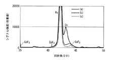
本願発明では、磁気記録パターンを構成する周囲の磁性層を反応性プラズマもしくはプラズマ中のイオン化した成分にさらし、該箇所の磁性層を非晶質化して製造することを特徴とする。磁性層を反応性イオン等に晒した場合、該箇所には磁性合金のイオン化物が形成する。例えば、特許文献7に記載されたように、Co系磁性合金をフッ素イオンプラズマにさらした場合、Co系磁性合金はフッ化コバルトとなり非磁性となる。すなわち、反応性プラズマに含まれるイオンは反応性が高いため、容易に磁性合金等と反応するからである。本願発明の磁気記録媒体の製造方法では、反応性イオン等にさらした磁性層を、磁性合金とイオンと反応させ、その反応物により磁性合金を非磁性化するのではなく、磁性合金を非晶質化して非磁性化することを特徴とする。これは、磁性層を非磁性化するために用いたイオンが、磁気記録パターンを構成する周囲の磁性合金に徐々に拡散し、該箇所の磁気特性を経時的に低下させることを防ぐためである。
磁性合金と反応性プラズマとを反応させ、該箇所の磁性合金を非晶質化する方法としては、磁性合金に反応性プラズマ中のイオンを衝突させて、該箇所の構造を物理的に壊す方法を用いることができる。また、磁性合金と反応性プラズマ中のイオンとを反応させ、磁性合金のイオン化物を生成させ、その後、磁性合金のイオン化による化合物のみを脱離させる方法が考えられる。例えば、Co系磁性合金を反応性フッ素イオンにさらして非磁性のフッ化コバルトを形成した後、このフッ化コバルトを加熱してフッ素のみを脱離させ、結晶構造が壊れた非晶質状態のCo系合金を形成させる方法がある。このような非晶質状態の磁性合金の製造条件は、磁性合金の組成、反応性プラズマに含まれるイオンの種類、反応圧力、反応時間、温度等を適宜設定することにより定めることができる。例えば、図5は、70Co−5Cr−15Pt−10SiO2磁性合金と、CF4を用いて発生させた反応性プラズマとの反応生成物のX線回折結果である。図5(a)は、反応性プラズマとの反応前の磁性膜の回折結果である。図中、回折角42度付近にある大きなシグナルは磁性膜の下にあるRu中間層の回折ピーク、43度付近にあるシグナルは磁性合金中のCoの回折ピークである。図5(b)はこの磁性膜を、フッ素イオンを含む反応性プラズマに60秒間さらした結果である。処理条件は、CF4を10cc/分、O2を90cc/分を用い、プラズマ発生のための投入電力は200W、装置内の圧力は0.5Paとし、基板バイアスを200Wとした。なお、処理時の基板温度は約150℃である。この反応により43度付近のピークは消失したが、フッ化コバルトに起因するピークは現れていない。また、42度付近のRu中間層のピークはそのままである。この結果は、Co系磁性合金が結晶性を失い非晶質化したことを示している。さらに、図5(c)は図5(a)の磁性膜をフッ素イオンを含む反応性プラズマにさらした場合であるが、図5(b)での条件に対し、基板バイアスを印加せず、また、処理ガスに酸素を添加せずにCF4のみを用いて処理した場合である。この場合、43度付近のピークは消失し、42度付近のRu中間層のピークはそのままであるが、35度、41度、44度付近にフッ化コバルトに起因するピークが現れている。
本願発明者の研究によると、磁性膜を、ハロゲンイオンを含む反応性プラズマにより改質するに際し、磁性合金のハロゲン化またはモルファス化を制御する方法としては下記がある。
1)基板にバイアス電圧を印加すると非晶質化が進行しやすくなる。これは、磁性膜において、ハロゲンイオンによるハロゲン化反応に比べ、イオンの衝撃による結晶構造の破壊が進行しやすくなるためと考えられる。
2)反応性プラズマ中のハロゲンがラジカル状態の場合は磁性粒のハロゲン化が進行しやすく、イオン状態の場合は磁性粒の非晶質化が進行しやすい。これはハロゲンが有する反応性に差が生ずるためと考えられる。
3)ハロゲンを含むガスにCF4を用いると磁性粒のハロゲン化が進行しやすく、SF6を用いると非晶質化が進行しやすい。これはハロゲン化ガスの特質によるものと考えられる。
4)反応性プラズマに酸素を加えると磁性粒の非晶質化が進行しやすい。磁性粒子のハロゲン化より酸化の方が進行し易いためと考えられる。
5)磁性層が、粒界に酸化物を有するグラニュラー構造の場合は、ハロゲンイオンによる反応が酸化物から進行するため、磁性粒子のハロゲン化が進行しにくくなる。
The present invention relates to a magnetic recording medium having a magnetic recording pattern that is magnetically separated on at least one surface of a nonmagnetic substrate. It is characterized in that it is produced by exposing the magnetic layer to an amorphous state by exposing it to an ionic plasma or an ionized component in the plasma. The method of manufacturing the magnetic recording medium of the present invention is a step of separating the magnetic recording pattern portion by physically cutting the magnetic recording layer by ion milling or the like, unlike the conventional manufacturing method, when magnetically separating the magnetic recording pattern portion. No dust generation occurs, and there is no step of damaging the magnetic layer, such as implanting ions into the magnetic recording layer.
The present invention is characterized in that it is manufactured by exposing the surrounding magnetic layer constituting the magnetic recording pattern to reactive plasma or an ionized component in the plasma, and amorphizing the magnetic layer at that location. When the magnetic layer is exposed to reactive ions or the like, an ionized product of a magnetic alloy is formed at the location. For example, as described in Patent Document 7, when a Co-based magnetic alloy is exposed to fluorine ion plasma, the Co-based magnetic alloy becomes cobalt fluoride and becomes non-magnetic. That is, the ions contained in the reactive plasma are highly reactive and thus easily react with a magnetic alloy or the like. In the method for manufacturing a magnetic recording medium of the present invention, the magnetic layer exposed to reactive ions or the like is reacted with the magnetic alloy and ions, and the magnetic alloy is not made amorphous by the reaction product. It is characterized by being made non-magnetic by quality. This is to prevent the ions used to demagnetize the magnetic layer from gradually diffusing into the surrounding magnetic alloy constituting the magnetic recording pattern and degrading the magnetic properties of the portion over time. .
As a method of making a magnetic alloy and reactive plasma react to amorphize the magnetic alloy at the location, a method of physically destroying the structure of the location by colliding ions in the reactive plasma with the magnetic alloy Can be used. Further, a method is conceivable in which the magnetic alloy is reacted with ions in the reactive plasma to generate an ionized product of the magnetic alloy, and then only the compound resulting from the ionization of the magnetic alloy is desorbed. For example, a Co-based magnetic alloy is exposed to reactive fluorine ions to form non-magnetic cobalt fluoride, and then the cobalt fluoride is heated to desorb only fluorine, so that the crystalline structure is broken. There is a method of forming a Co-based alloy. The production conditions for such an amorphous magnetic alloy can be determined by appropriately setting the composition of the magnetic alloy, the type of ions contained in the reactive plasma, the reaction pressure, the reaction time, the temperature, and the like. For example, Figure 5 is an X-ray diffraction results of 70Co-5Cr-15Pt-10SiO 2 and the magnetic alloy, the reaction product of a reactive plasma generated by using CF 4. FIG. 5A shows the diffraction result of the magnetic film before the reaction with the reactive plasma. In the figure, the large signal near the diffraction angle of 42 degrees is the diffraction peak of the Ru intermediate layer under the magnetic film, and the signal near 43 degrees is the diffraction peak of Co in the magnetic alloy. FIG. 5B shows the result of exposing this magnetic film to a reactive plasma containing fluorine ions for 60 seconds. The treatment conditions were 10 cc / min for CF 4 and 90 cc / min for O 2 , the input power for plasma generation was 200 W, the pressure in the apparatus was 0.5 Pa, and the substrate bias was 200 W. In addition, the substrate temperature at the time of a process is about 150 degreeC. Although the peak near 43 degrees disappeared by this reaction, no peak due to cobalt fluoride appears. Moreover, the peak of the Ru intermediate layer near 42 degrees remains as it is. This result shows that the Co-based magnetic alloy has lost crystallinity and has become amorphous. Further, FIG. 5C shows a case where the magnetic film of FIG. 5A is exposed to a reactive plasma containing fluorine ions, but no substrate bias is applied to the conditions in FIG. In addition, this is a case where processing is performed using only CF 4 without adding oxygen to the processing gas. In this case, the peak near 43 degrees disappears and the peak of the Ru intermediate layer near 42 degrees remains as it is, but peaks attributed to cobalt fluoride appear around 35 degrees, 41 degrees, and 44 degrees.
According to the study of the present inventor, there are the following methods for controlling the halogenation or morphogenesis of a magnetic alloy when the magnetic film is modified by reactive plasma containing halogen ions.
1) When a bias voltage is applied to the substrate, amorphization easily proceeds. This is presumably because in the magnetic film, the crystal structure is more easily broken by the impact of ions than in the halogenation reaction by halogen ions.
2) When the halogen in the reactive plasma is in a radical state, the halogenation of the magnetic particles is likely to proceed, and when it is in the ionic state, the amorphization of the magnetic particles is likely to proceed. This is presumably because a difference occurs in the reactivity of halogen.
3) When CF 4 is used for the gas containing halogen, the halogenation of the magnetic grains is likely to proceed, and when SF 6 is used, the amorphization is likely to proceed. This is thought to be due to the nature of the halogenated gas.
4) When oxygen is added to the reactive plasma, the amorphization of the magnetic grains tends to proceed. This is probably because oxidation proceeds more easily than halogenation of magnetic particles.
5) When the magnetic layer has a granular structure having an oxide at the grain boundary, the reaction by the halogen ions proceeds from the oxide, so that the halogenation of the magnetic particles is difficult to proceed.
本願発明の磁気記録パターン部とは、磁気記録パターンが1ビットごとに一定の規則性をもって配置された、いわゆるパターンドメディアや、磁気記録パターンが、トラック状に配置されたメディアや、その他、サーボ信号パターン等を含んでいる。 The magnetic recording pattern portion of the present invention is a so-called patterned medium in which the magnetic recording pattern is arranged with a certain regularity for each bit, a medium in which the magnetic recording pattern is arranged in a track shape, or other servo Including signal patterns.
この中で本願発明は、磁気的に分離した磁気記録パターンが、磁気記録トラック及びサーボ信号パターンである、いわゆる、ディスクリート型磁気記録媒体に適用するのが、その製造における簡便性から好ましい。 Of these, the present invention is preferably applied to a so-called discrete type magnetic recording medium in which magnetically separated magnetic recording patterns are magnetic recording tracks and servo signal patterns, from the viewpoint of simplicity in manufacturing.
本発明を、ディスクリート型磁気記録媒体を例にして詳細に説明する。 The present invention will be described in detail by taking a discrete magnetic recording medium as an example.
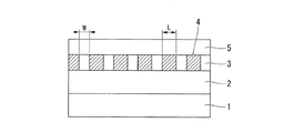
図1に本発明のディスクリート型磁気記録媒体の断面構造を例示す。本発明の磁気記録媒体30は、非磁性基板1の表面に軟磁性層および中間層2、磁気的パターンが形成された磁性層3および非磁性化層4と保護膜5が形成されており、さらに最表面に図示省略の潤滑膜が形成された構造を有している。
FIG. 1 shows an example of a cross-sectional structure of a discrete magnetic recording medium of the present invention. In the
記録密度を高めるため、磁気的パターンを有する磁性層3の磁性部幅Wは200nm以下、非磁性部幅Lは100nm以下とすることが好ましい。従ってトラックピッチP(=W+L)は300nm以下の範囲で、記録密度を高めるためにはできるだけ狭くする。
In order to increase the recording density, the magnetic part width W of the
本発明で使用する非磁性基板としては、Alを主成分とした例えばAl−Mg合金等のAl合金基板や、通常のソーダガラス、アルミノシリケート系ガラス、結晶化ガラス類、シリコン、チタン、セラミックス、各種樹脂からなる基板など、非磁性基板であれば任意のものを用いることができる。中でもAl合金基板や結晶化ガラス等のガラス製基板またはシリコン基板を用いることが好ましい。またこれら基板の平均表面粗さ(Ra)は、1nm以下、さらには0.5nm以下であることが好ましく、中でも0.1nm以下であることが好ましい。 Nonmagnetic substrates used in the present invention include Al alloy substrates such as Al-Mg alloys mainly composed of Al, ordinary soda glass, aluminosilicate glass, crystallized glass, silicon, titanium, ceramics, Any nonmagnetic substrate such as a substrate made of various resins can be used. Among them, it is preferable to use a glass substrate such as an Al alloy substrate or crystallized glass, or a silicon substrate. The average surface roughness (Ra) of these substrates is preferably 1 nm or less, more preferably 0.5 nm or less, and particularly preferably 0.1 nm or less.
上記のような非磁性基板の表面に形成される磁性層は、面内磁気記録層でも垂直磁気記録層でもかまわないがより高い記録密度を実現するためには垂直磁気記録層が好ましい。これら磁気記録層は主としてCoを主成分とする合金から形成するのが好ましい。 The magnetic layer formed on the surface of the nonmagnetic substrate as described above may be an in-plane magnetic recording layer or a perpendicular magnetic recording layer, but a perpendicular magnetic recording layer is preferable in order to realize a higher recording density. These magnetic recording layers are preferably formed from an alloy mainly containing Co as a main component.
例えば、面内磁気記録媒体用の磁気記録層としては、非磁性のCrMo下地層と強磁性のCoCrPtTa磁性層からなる積層構造が利用できる。 For example, as a magnetic recording layer for an in-plane magnetic recording medium, a laminated structure composed of a nonmagnetic CrMo underlayer and a ferromagnetic CoCrPtTa magnetic layer can be used.
垂直磁気記録媒体用の磁気記録層としては、例えば軟磁性のFeCo合金(FeCoB、FeCoSiB、FeCoZr、FeCoZrB、FeCoZrBCuなど)、FeTa合金(FeTaN、FeTaCなど)、Co合金(CoTaZr、CoZrNB、CoBなど)等からなる裏打ち層と、Pt、Pd、NiCr、NiFeCrなどの配向制御膜と、必要によりRu等の中間膜、及び60Co−15Cr−15Pt合金や70Co−5Cr−15Pt−10SiO2合金からなる磁性層を積層したものを利用することがきる。 Examples of magnetic recording layers for perpendicular magnetic recording media include soft magnetic FeCo alloys (FeCoB, FeCoSiB, FeCoZr, FeCoZrB, FeCoZrBCu, etc.), FeTa alloys (FeTaN, FeTaC, etc.), Co alloys (CoTaZr, CoZrNB, CoB, etc.). A backing layer made of, etc., an orientation control film such as Pt, Pd, NiCr, NiFeCr, an intermediate film such as Ru, if necessary, and a magnetic layer made of 60Co-15Cr-15Pt alloy or 70Co-5Cr-15Pt-10SiO 2 alloy Can be used.
磁気記録層の厚さは、3nm以上20nm以下、好ましくは5nm以上15nm以下とする。磁気記録層は使用する磁性合金の種類と積層構造に合わせて、十分なヘッド出入力が得られるように形成すればよい。磁性層の膜厚は再生の際に一定以上の出力を得るにはある程度以上の磁性層膜厚が必要であり、一方で記録再生特性を表す諸パラメーターは出力の上昇とともに劣化するのが通例であるため、最適な膜厚に設定する必要がある。 The thickness of the magnetic recording layer is 3 nm to 20 nm, preferably 5 nm to 15 nm. The magnetic recording layer may be formed so as to obtain sufficient head input / output according to the type of magnetic alloy used and the laminated structure. The film thickness of the magnetic layer requires a certain thickness of the magnetic layer in order to obtain a certain level of output during playback. On the other hand, parameters indicating recording / playback characteristics usually deteriorate as the output increases. Therefore, it is necessary to set an optimum film thickness.
通常、磁気記録層はスパッタ法により薄膜として形成する。 Usually, the magnetic recording layer is formed as a thin film by sputtering.
本願発明では、磁気記録トラック及びサーボ信号パターン部を磁気的に分離する領域を、すでに成膜された磁性層を反応性プラズマにさらして該箇所の磁性層を非晶質化し、該箇所の磁気特性を改質することにより形成することを特徴とする。 In the present invention, the magnetic recording track and the servo signal pattern portion are magnetically separated from each other, the magnetic layer already formed is exposed to reactive plasma to amorphize the magnetic layer, and the magnetic layer It is formed by modifying the characteristics.
磁性層の磁気特性の改質とは、具体的には、磁性層の保磁力、残留磁化等を変化させることを指し、その変化とは、保磁力を下げ、残留磁化を下げることを指す。 Specifically, the modification of the magnetic properties of the magnetic layer refers to changing the coercive force, remanent magnetization, etc. of the magnetic layer, and the change refers to reducing the coercive force and reducing the remanent magnetization.
本願発明では特に、磁気特性の改質として、反応性プラズマにさらした箇所の磁性層の磁化量、または、保磁力を、磁化量を当初の75%以下、より好ましくは50%以下、当初の保磁力の50%以下、より好ましくは20%以下とする方法を採用するのが好ましい。このような方法を用いてディスクリートトラック型磁気記録媒体を製造することにより、本媒体に磁気記録を行う際の書きにじみをなくし、高い面記録密度の磁気記録媒体を提供することが可能となる。 Particularly in the present invention, as a modification of the magnetic characteristics, the magnetization amount or coercivity of the magnetic layer exposed to the reactive plasma is set to 75% or less, more preferably 50% or less of the initial magnetization amount. It is preferable to adopt a method in which the coercive force is 50% or less, more preferably 20% or less. By manufacturing a discrete track type magnetic recording medium using such a method, it is possible to eliminate writing bleeding when performing magnetic recording on this medium and to provide a magnetic recording medium having a high surface recording density.
本願発明では、磁気記録トラック及びサーボ信号パターン部を磁気的に分離する箇所を、すでに成膜された磁性層を反応性プラズマにさらして磁性層を非晶質化することにより実現する。 In the present invention, the magnetic recording track and the servo signal pattern portion are magnetically separated by exposing the already formed magnetic layer to reactive plasma to make the magnetic layer amorphous.
本願発明で、磁性層を非晶質化するとは、磁性層の原子配列を、長距離秩序を持たない不規則な原子配列の形態とすることを指し、より具体的には、2nm未満の微結晶粒がランダムに配列した状態とすることを指す。そしてこの原子配列状態を分析手法により確認する場合は、X線回折または電子線回折により、結晶面を表すピークが認められず、また、ハロー(ブロードなシグナル)が認められるのみの状態とする。 In the present invention, making the magnetic layer amorphous means that the atomic arrangement of the magnetic layer is in the form of an irregular atomic arrangement having no long-range order. It refers to a state in which crystal grains are randomly arranged. When this atomic arrangement state is confirmed by an analysis method, a peak representing a crystal plane is not recognized by X-ray diffraction or electron beam diffraction, and only a halo (broad signal) is recognized.
本願発明の反応性プラズマとしては、誘導結合プラズマ(ICP;Inductively Coupled Plasma)や反応性イオンプラズマ(RIE;Reactive Ion Plasma)が例示できる。 Examples of the reactive plasma of the present invention include inductively coupled plasma (ICP) and reactive ion plasma (RIE).
誘導結合プラズマとは、気体に高電圧をかけることによってプラズマ化し、さらに高周波数の変動磁場によってそのプラズマ内部に渦電流によるジュール熱を発生させることによって得られる高温のプラズマである。誘導結合プラズマは電子密度が高く、従来のイオンビームを用いてディスクリートトラックメディアを製造する場合に比べ、広い面積の磁性膜において、高い効率で磁気特性の改質を実現することができる。 The inductively coupled plasma is a high-temperature plasma obtained by generating a plasma by applying a high voltage to a gas and generating Joule heat due to an eddy current in the plasma by a high-frequency variable magnetic field. The inductively coupled plasma has a high electron density, and can improve the magnetic properties with high efficiency in a magnetic film having a large area as compared with the case where a discrete track medium is manufactured using a conventional ion beam.
反応性イオンプラズマとは、プラズマ中にO2、SF6、CHF3、CF4、CCl4等の反応性ガスを加えた反応性の高いプラズマである。このようなプラズマを本願発明の反応性プラズマとして用いることにより、磁性膜の磁気特性の改質をより高い効率で実現することが可能となる。 The reactive ion plasma is a highly reactive plasma in which a reactive gas such as O 2 , SF 6 , CHF 3 , CF 4 , or CCl 4 is added to the plasma. By using such plasma as the reactive plasma of the present invention, it is possible to realize the modification of the magnetic properties of the magnetic film with higher efficiency.
本願発明では、成膜された磁性層を反応性プラズマにさらすことにより磁性層を改質するが、この改質は、磁性層を構成する磁性金属と反応性プラズマ中の原子またはイオンとの反応により実現するのが好ましい。反応とは、磁性金属に反応性プラズマ中の原子等が侵入し、磁性金属の結晶構造が変化すること、磁性金属の組成が変化すること、磁性金属が酸化すること、磁性金属か窒化すること、磁性金属が珪化すること等が例示できる。 In the present invention, the magnetic layer is modified by exposing the deposited magnetic layer to reactive plasma. This modification is a reaction between the magnetic metal constituting the magnetic layer and atoms or ions in the reactive plasma. It is preferable to implement by. Reactions include atoms in reactive plasma entering the magnetic metal, changing the crystal structure of the magnetic metal, changing the composition of the magnetic metal, oxidizing the magnetic metal, or nitriding the magnetic metal. For example, the magnetic metal is silicified.
本願発明では特に、反応性プラズマとして酸素原子を含有させ、磁性層を構成する磁性金属と反応性プラズマ中の酸素原子とを反応させることにより、磁性層を酸化させるのが好ましい。磁性層を部分的に酸化させることにより、酸化部分の残留磁化及び保磁力等を効率よく低減させることが可能となるため、短時間の反応性プラズマ処理により、磁気的に分離した磁気記録パターンを有する磁気記録媒体を製造することが可能となるからである。また反応性プラズマ中に酸素原子を含有させることにより磁性層の非晶質化を促進することが可能となる。 Particularly in the present invention, it is preferable to oxidize the magnetic layer by containing oxygen atoms as reactive plasma and reacting the magnetic metal constituting the magnetic layer with oxygen atoms in the reactive plasma. By partially oxidizing the magnetic layer, it is possible to efficiently reduce the remanent magnetization and coercive force of the oxidized portion, so that magnetically separated magnetic recording patterns can be obtained by a short reactive plasma treatment. This is because a magnetic recording medium having the same can be manufactured. Moreover, it becomes possible to promote the amorphization of the magnetic layer by containing oxygen atoms in the reactive plasma.
本願発明では、反応性プラズマに、ハロゲン原子を含有させるのが好ましい。またハロゲン原子としてはF原子を用いるのが特に好ましい。ハロゲン原子は、酸素原子と一緒に反応性プラズマ中に添加して用いても良いし、また酸素原子を用いずに反応性プラズマ中に添加しても良い。前述のように、反応性プラズマに酸素原子等を加えることにより、磁性層を構成する磁性金属と酸素原子等が反応して磁性層の磁気特性を改質させることが可能となる。この際、反応性プラズマにハロゲン原子を含有させることにより、この反応性をさらに高めることが可能となる。また、反応性プラズマ中に酸素原子を添加していない場合においても、ハロゲン原子が磁性合金と反応して、磁性層の磁気特性を改質させることが可能となる。この理由の詳細は明らかではないが、反応性プラズマ中のハロゲン原子が、磁性層の表面に形成している異物をエッチングし、これにより磁性層の表面が清浄化し、磁性層の反応性が高まることが考えられる。また、清浄化した磁性層表面とハロゲン原子とが高い効率で反応することが考えられる。このような効果を有するハロゲン原子としてF原子を用いるのが特に好ましい。
本願発明では、磁性層の表面を部分的に反応性プラズマにさらし、該箇所の磁性層の磁気特性を改質する工程を、磁性層を、酸素を含有するプラズマにさらす第1の工程と、その後、磁性層を、ハロゲンを含有するプラズマにさらす第2の工程により行うのが好ましい。このような工程を採用することにより、磁性層の磁気特性の改質速度を高め、また、磁性層の残留磁化及び保磁力等を効率よく低減させることが可能となる。その理由は、発明者らの研究によると、磁性層を酸素含有プラズマにさらすことにより、磁性粒子の粒界部分が優先的に酸化し、その酸化領域が粒界に沿って膜厚方向に進行し、その後、磁性層をハロゲン含有プラズマにさらすと、その磁性粒子の粒界における酸化領域が優先的にハロゲンと反応して該箇所の結晶構造を破壊し、その反応領域が粒界から磁性粒子に向けて進行するためである。これにより、単に磁性層を酸素プラズマやハロゲンプラズマにさらした場合に比べ、磁性層の磁気特性の改質が高速となり、また、磁性粒子とハロゲンとの反応も効率良く進行するため、磁性層の残留磁化及び保磁力等を効率よく低減させることが可能となるのである。
本願発明では、磁性層の表面を部分的に反応性プラズマにさらす工程の前に、磁性層の表面に、部分的にイオン注入する工程を設けるのが好ましい。このような工程を設けることにより、磁性層の磁気特性の改質をさらに高速に行うことが可能となる。その理由は、発明者らの研究によると、磁性層の表面に部分的にイオン注入することにより、磁性層の表面が活性となり、その後に行う磁性層を反応性プラズマにさらす工程において、磁性層とプラズマとの反応性がより高まるためである。
本願発明では、磁性層に注入するイオンとして、アルゴンまたは窒素等の不活性のイオンを用いるのが好ましい。このような不活性なイオンは、その後に行う、磁性層と反応性プラズマとの反応に悪影響することが少ないからである。
In the present invention, it is preferable that halogen atoms are contained in the reactive plasma. Further, it is particularly preferable to use an F atom as the halogen atom. The halogen atom may be added to the reactive plasma together with the oxygen atom, or may be added to the reactive plasma without using the oxygen atom. As described above, by adding oxygen atoms or the like to the reactive plasma, the magnetic metal constituting the magnetic layer reacts with oxygen atoms or the like, thereby improving the magnetic properties of the magnetic layer. At this time, the reactivity can be further increased by adding halogen atoms to the reactive plasma. Even when oxygen atoms are not added to the reactive plasma, the halogen atoms react with the magnetic alloy, and the magnetic properties of the magnetic layer can be improved. Although the details of this reason are not clear, halogen atoms in the reactive plasma etch foreign matter formed on the surface of the magnetic layer, thereby cleaning the surface of the magnetic layer and increasing the reactivity of the magnetic layer. It is possible. It is also conceivable that the cleaned magnetic layer surface and halogen atoms react with high efficiency. It is particularly preferable to use an F atom as the halogen atom having such an effect.
In the present invention, the step of partially exposing the surface of the magnetic layer to reactive plasma and modifying the magnetic properties of the magnetic layer at the location, the first step of exposing the magnetic layer to plasma containing oxygen, Thereafter, the second step is preferably performed by exposing the magnetic layer to a halogen-containing plasma. By adopting such a process, it is possible to increase the modification speed of the magnetic characteristics of the magnetic layer and to efficiently reduce the residual magnetization, coercive force and the like of the magnetic layer. The reason for this is that, according to studies by the inventors, by exposing the magnetic layer to an oxygen-containing plasma, the grain boundary portion of the magnetic particles is preferentially oxidized, and the oxidized region advances in the film thickness direction along the grain boundary. Thereafter, when the magnetic layer is exposed to a halogen-containing plasma, the oxidized region at the grain boundary of the magnetic particle preferentially reacts with the halogen to destroy the crystal structure of the part, and the reaction region is separated from the grain boundary to the magnetic particle. It is because it progresses toward. As a result, compared with the case where the magnetic layer is simply exposed to oxygen plasma or halogen plasma, the modification of the magnetic properties of the magnetic layer becomes faster, and the reaction between the magnetic particles and the halogen proceeds more efficiently. It is possible to efficiently reduce the remanent magnetization and the coercive force.
In the present invention, it is preferable to provide a step of partially ion-implanting the surface of the magnetic layer before the step of partially exposing the surface of the magnetic layer to reactive plasma. By providing such a process, the magnetic properties of the magnetic layer can be modified at a higher speed. The reason for this is that, according to the study by the inventors, the surface of the magnetic layer is activated by partial ion implantation on the surface of the magnetic layer, and the magnetic layer is then exposed to reactive plasma in the subsequent step. This is because the reactivity between and the plasma is further increased.
In the present invention, it is preferable to use inert ions such as argon or nitrogen as ions to be implanted into the magnetic layer. This is because such inactive ions rarely adversely affect the subsequent reaction between the magnetic layer and the reactive plasma.
本願発明では、磁性層の表面に、磁気記録パターンに合致させたレジストパターンを形成後、その表面の反応性プラズマにより処理し、その後、レジストを除去して保護層を再形成後、潤滑材を塗布して磁気記録媒体を製造する工程を採用するのが好ましい。このような方法を採用することにより磁性層と反応性プラズマとの反応性をより高めることが可能となるからである。 In the present invention, after forming a resist pattern matching the magnetic recording pattern on the surface of the magnetic layer, the surface is treated with reactive plasma, and then the resist is removed to re-form the protective layer, and then the lubricant is added. It is preferable to employ a step of coating to produce a magnetic recording medium. This is because it is possible to further increase the reactivity between the magnetic layer and the reactive plasma by adopting such a method.
さらに本願発明では、磁性層の上に保護層を形成し、その表面に、磁気記録パターンに合致させたレジストパターンを形成し、その後、反応性プラズマによる磁性層の改質処理を行う工程も採用できる。このような工程を採用することにより、反応性プラズマ処理の後に保護膜を形成する必要がなくなり、製造工程が簡便になり、生産性の向上および磁気記録媒体の製造工程における汚染の低減の効果が得られる。発明者らは、磁性層の表面に保護膜を形成した後においても、磁性層と反応性プラズマとの反応を生じさせることが可能であることを実験により確認している。保護膜で覆われているはずの磁性層において反応性プラズマとの反応が生じている理由は、発明者らの考えによると、保護膜に空隙等が存在し、その空隙からプラズマ中の反応性イオンが侵入し、反応性イオンが磁性金属と反応することがある。また、保護膜中を反応性イオンが拡散し、反応性イオンが磁性層まで到達することも考えられる。 Furthermore, in the present invention, a process is also employed in which a protective layer is formed on the magnetic layer, a resist pattern matching the magnetic recording pattern is formed on the surface, and then the magnetic layer is modified by reactive plasma. it can. By adopting such a process, it is not necessary to form a protective film after the reactive plasma treatment, the manufacturing process is simplified, and the effect of improving productivity and reducing contamination in the manufacturing process of the magnetic recording medium is achieved. can get. The inventors have confirmed through experiments that it is possible to cause a reaction between the magnetic layer and reactive plasma even after a protective film is formed on the surface of the magnetic layer. The reason why the reaction with the reactive plasma occurs in the magnetic layer that should have been covered with the protective film is that, according to the inventors' thoughts, there are voids in the protective film and the reactivity in the plasma from the voids. Ions may enter and reactive ions may react with the magnetic metal. It is also conceivable that reactive ions diffuse in the protective film and the reactive ions reach the magnetic layer.
なお、前記レジストパターン形成には、磁性層もしくは磁性層に続いて製膜される保護膜にレジストを塗布し、その上から直接スタンパーを密着させ、高圧でプレスすることにより、レジストパターンを形成する方法が採用できる。また、通常のフォトリソグラフィー技術を適用してパターン形成を行うこともできる。レジストとしては、熱硬化型樹脂、UV硬化型樹脂、SOG等を用いることができる。 The resist pattern is formed by applying a resist to a magnetic layer or a protective film formed subsequent to the magnetic layer, and then directly contacting the stamper and pressing at a high pressure. The method can be adopted. Moreover, pattern formation can also be performed by applying a normal photolithography technique. As the resist, thermosetting resin, UV curable resin, SOG, or the like can be used.
前記のプロセスで用いられるスタンパーは、例えば、金属プレートに電子線描画などの方法を用いて微細なトラックパターンを形成したものが使用でき、材料としてはプロセスに耐えうる硬度、耐久性が要求される。たとえばNiなどが使用できるが、前述の目的に合致するものであれば材料は問わない。スタンパーには、通常のデータを記録するトラックの他にバーストパターン、グレイコードパターン、プリアンブルパターンといったサーボ信号のパターンも形成できる。 As the stamper used in the above-mentioned process, for example, a metal plate formed with a fine track pattern using a method such as electron beam drawing can be used, and the material is required to have hardness and durability that can withstand the process. . For example, Ni can be used, but any material can be used as long as it meets the above-mentioned purpose. In addition to the tracks on which normal data is recorded, servo signal patterns such as burst patterns, gray code patterns, and preamble patterns can be formed on the stamper.
反応性プラズマ処理を行った後のレジストの除去は、ドライエッチング、反応性イオンエッチング、イオンミリング、湿式エッチング等の手法を用いることができる。 Removal of the resist after the reactive plasma treatment can be performed using a technique such as dry etching, reactive ion etching, ion milling, or wet etching.
保護膜5の形成は、一般的にはDiamond Like Carbonの薄膜をP−CVDなどを用いて成膜する方法が行われるが特に限定されるものではない。
The
保護膜としては、炭素(C)、水素化炭素(HxC)、窒素化炭素(CN)、アルモファスカーボン、炭化珪素(SiC)等の炭素質層やSiO2、Zr2O3、TiNなど、通常用いられる保護膜材料を用いることができる。また、保護膜が2層以上の層から構成されていてもよい。 Examples of the protective film include carbonaceous layers such as carbon (C), hydrogenated carbon (HxC), nitrogenated carbon (CN), alumocarbon, silicon carbide (SiC), SiO 2 , Zr 2 O 3 , TiN, etc. A commonly used protective film material can be used. Further, the protective film may be composed of two or more layers.
保護膜5の膜厚は10nm未満とする必要がある。保護膜の膜厚が10nmを越えるとヘッドと磁性層との距離が大きくなり、十分な出入力信号の強さが得られなくなるからである。
The film thickness of the
保護膜の上には潤滑層を形成することが好ましい。潤滑層に用いる潤滑剤としては、フッ素系潤滑剤、炭化水素系潤滑剤及びこれらの混合物等が挙げられ、通常1〜4nmの厚さで潤滑層を形成する。 A lubricating layer is preferably formed on the protective film. Examples of the lubricant used for the lubricating layer include a fluorine-based lubricant, a hydrocarbon-based lubricant, and a mixture thereof, and the lubricating layer is usually formed with a thickness of 1 to 4 nm.
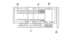
次に、本発明の磁気記録再生装置の構成を図2に示す。本発明の磁気記録再生装置は、上述の本発明の磁気記録媒体30と、これを記録方向に駆動する媒体駆動部11と、記録部と再生部からなる磁気ヘッド27と、磁気ヘッド27を磁気記録媒体30に対して相対運動させるヘッド駆動部28と、磁気ヘッド27への信号入力と磁気ヘッド27からの出力信号再生を行うための記録再生信号処理手段を組み合わせた記録再生信号系29とを具備したものである。これらを組み合わせることにより記録密度の高い磁気記録装置を構成することが可能となる。磁気記録媒体の記録トラックを磁気的に不連続に加工したことによって、従来はトラックエッジ部の磁化遷移領域の影響を排除するために再生ヘッド幅を記録ヘッド幅よりも狭くして対応していたものを、両者をほぼ同じ幅にして動作させることができる。これにより十分な再生出力と高いSNRを得ることができるようになる。
Next, the configuration of the magnetic recording / reproducing apparatus of the present invention is shown in FIG. The magnetic recording / reproducing apparatus of the present invention includes the above-described
さらに上述の磁気ヘッドの再生部をGMRヘッドあるいはTMRヘッドで構成することにより、高記録密度においても十分な信号強度を得ることができ、高記録密度を持った磁気記録装置を実現することができる。またこの磁気ヘッドの浮上量を0.005μm〜0.020μmと従来より低い高さで浮上させると、出力が向上して高い装置SNRが得られ、大容量で高信頼性の磁気記録装置を提供することができる。また、最尤復号法による信号処理回路を組み合わせるとさらに記録密度を向上でき、例えば、トラック密度100kトラック/インチ以上、線記録密度1000kビット/インチ以上、1平方インチ当たり100Gビット以上の記録密度で記録・再生する場合にも十分なSNRが得られる。 Furthermore, by configuring the reproducing section of the magnetic head as a GMR head or TMR head, a sufficient signal intensity can be obtained even at a high recording density, and a magnetic recording apparatus having a high recording density can be realized. . Also, when the flying height of this magnetic head is lowered to 0.005 μm to 0.020 μm, which is lower than the conventional height, the output is improved and a high device SNR is obtained, and a large capacity and high reliability magnetic recording device is provided. can do. Further, by combining the signal processing circuit based on the maximum likelihood decoding method, the recording density can be further improved. For example, the track density is 100 k tracks / inch or more, the linear recording density is 1000 k bits / inch or more, and the recording density is 100 G bits or more per square inch. A sufficient SNR can also be obtained when recording / reproducing.
(実施例1)
HD用ガラス基板をセットした真空チャンバをあらかじめ1.0×10⁻⁵Pa以下に真空排気した。ここで使用したガラス基板はLi2Si2O5、Al2O3−K2O、Al2O3−K2O、MgO−P2O5、Sb2O3−ZnOを構成成分とする結晶化ガラスを材質とし、外径65mm、内径20mm、平均表面粗さ(Ra)は2オングストローム(単位:Å、0.2nm)である。
Example 1
The vacuum chamber in which the glass substrate for HD was set was evacuated to 1.0 × 10 −5 Pa or less in advance. The glass substrate used here is composed of Li 2 Si 2 O 5 , Al 2 O 3 —K 2 O, Al 2 O 3 —K 2 O, MgO—P 2 O 5 , and Sb 2 O 3 —ZnO. It is made of crystallized glass and has an outer diameter of 65 mm, an inner diameter of 20 mm, and an average surface roughness (Ra) of 2 angstroms (unit: Å, 0.2 nm).
該ガラス基板にDCスパッタリング法を用いて、軟磁性層としてFeCoB、中間層としてRu、磁性層として70Co−5Cr−15Pt−10SiO2合金、P−CVD法を用いてC(カーボン)保護膜、フッ素系潤滑膜の順に薄膜を積層した。それぞれの層の膜厚は、FeCoB軟磁性層は600Å、Ru中間層は100Å、磁性層は150Å、C(カーボン)保護膜は平均4nmとした。 A DC sputtering method is used for the glass substrate, FeCoB as a soft magnetic layer, Ru as an intermediate layer, 70Co-5Cr-15Pt-10SiO 2 alloy as a magnetic layer, a C (carbon) protective film using a P-CVD method, fluorine Thin films were laminated in the order of the system lubricant film. The thickness of each layer was 600。 for the FeCoB soft magnetic layer, 100Å for the Ru intermediate layer, 150Å for the magnetic layer, and an average of 4 nm for the C (carbon) protective film.
この表面にUV硬化性樹脂を200nmの厚さで塗布し、この上に、あらかじめ用意していたNi製スタンパーを用いてインプリントを施した。スタンパーはトラックピッチが100nm、溝の深さは20nmとした。このスタンパーを使用して保護膜上のUV硬化性樹脂に対してインプリントを実施した。 A UV curable resin was applied to the surface with a thickness of 200 nm, and imprinting was performed thereon using a Ni stamper prepared in advance. The stamper had a track pitch of 100 nm and a groove depth of 20 nm. Using this stamper, imprinting was performed on the UV curable resin on the protective film.
この表面を反応性プラズマにさらして、UV硬化性樹脂で覆われていない箇所の磁性層の改質を行った。磁性層の反応性プラズマ処理は、アルバック社の誘導結合プラズマ装置NE550を用いた。プラズマの発生に用いるガスおよび条件としては、たとえばCF4を10cc/分、O2を90cc/分を用い、プラズマ発生のための投入電力は200W、装置内の圧力は0.5Paとし、基板バイアス200Wにて磁気記録媒体の表面を60秒間処理した。反応性プラズマ処理を行った箇所の磁性膜をX線回折法により調べたところ、Coに起因するシグナルは消失し、一方でフッ化コバルトに起因するシグナルは観察されず、該箇所は非晶質構造となったことが確認された。
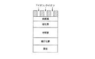
本実施例の製造方法を示す模式図を図3、製造条件を表1に示す。
This surface was exposed to reactive plasma to modify the magnetic layer in a portion not covered with the UV curable resin. The reactive plasma treatment of the magnetic layer was performed using an inductively coupled plasma apparatus NE550 manufactured by ULVAC. As gas and conditions used for generating plasma, for example, CF 4 is 10 cc / min, O 2 is 90 cc / min, input power for generating plasma is 200 W, pressure in the apparatus is 0.5 Pa, substrate bias The surface of the magnetic recording medium was treated for 60 seconds at 200W. When the magnetic film at the location where the reactive plasma treatment was performed was examined by X-ray diffraction, the signal due to Co disappeared, while the signal due to cobalt fluoride was not observed, and the location was amorphous. The structure was confirmed.
A schematic diagram showing the production method of this example is shown in FIG.
その後、磁気記録媒体表面のレジストをドライエッチングにより除去し、その表面にカーボン保護膜を成膜し、最後にフッ素系潤滑膜を塗布し、磁気記録媒体の製造を完了した。
(実施例2〜22)
実施例1と同様に磁気記録媒体を製造した。この際、反応性プラズマに用いるガス種、投入電力、反応圧力、反応時間を表1に示すように変化させた。実施例2〜22において、反応性プラズマ処理を行った箇所の磁性膜をX線回折法により調べたところ、Coに起因するシグナルは消失し、一方でフッ化コバルトに起因するシグナルは観察されず、実施例2〜22の全ての実施例において、該箇所は非晶質構造となったことが確認された。
(比較例)
実施例1と同様の条件で磁気記録媒体を製造したが、磁性層の反応性プラズマ処理に際して、基板にバイアス電圧を印加せず、また、プラズマガスに酸素を添加しなかった。製造した磁気記録媒体について、反応性プラズマ処理を行った箇所の磁性膜をX線回折法により調べたところ、Coに起因するシグナルは消失し、一方でフッ化コバルトに起因するシグナルが観察された。またCoの非晶質化に起因するブロードなシグナルは観察されなかった。
Thereafter, the resist on the surface of the magnetic recording medium was removed by dry etching, a carbon protective film was formed on the surface, and finally a fluorine-based lubricating film was applied to complete the manufacture of the magnetic recording medium.
(Examples 2 to 22)
A magnetic recording medium was manufactured in the same manner as in Example 1. At this time, the gas type, input power, reaction pressure, and reaction time used for the reactive plasma were changed as shown in Table 1. In Examples 2 to 22, when the magnetic film at the location where the reactive plasma treatment was performed was examined by the X-ray diffraction method, the signal attributed to Co disappeared, while the signal attributed to cobalt fluoride was not observed. In all of Examples 2 to 22, it was confirmed that the portion had an amorphous structure.
(Comparative example)
A magnetic recording medium was manufactured under the same conditions as in Example 1, but no bias voltage was applied to the substrate and oxygen was not added to the plasma gas during the reactive plasma treatment of the magnetic layer. Regarding the manufactured magnetic recording medium, the magnetic film at the location where the reactive plasma treatment was performed was examined by X-ray diffraction. As a result, the signal attributed to Co disappeared, while the signal attributed to cobalt fluoride was observed. . In addition, no broad signal due to Co amorphization was observed.
以上の方法で製造した実施例1〜22の磁気記録媒体の磁化減少量、保磁力減少量、電磁変換特性(SNRおよび3T−squash)、表面粗さ(Ra)、ヘッド浮上高さ(グライドアバランチ)を測定した。
電磁変換特性の評価はスピンスタンドを用いて実施した。このとき評価用のヘッドには、記録には垂直記録ヘッド、読み込みにはTuMRヘッドを用いたて、750kFCIの信号を記録したときのSNR値および3T−squashを測定した。図4に実施例1に示した磁気記録媒体の反応性プラズマによる処理前後の磁化量の変化を示す。また、表1に実施例1〜22の評価結果を示す。
Magnetization reduction amount, coercive force reduction amount, electromagnetic conversion characteristics (SNR and 3T-squash), surface roughness (Ra), head flying height (glide avalanche) of the magnetic recording media of Examples 1 to 22 manufactured by the above method ) Was measured.
Evaluation of electromagnetic conversion characteristics was performed using a spin stand. At this time, a perpendicular recording head was used for recording and a TuMR head was used for reading, and the SNR value and 3T-squash when a 750 kFCI signal was recorded were measured. FIG. 4 shows changes in the amount of magnetization before and after the treatment by the reactive plasma of the magnetic recording medium shown in Example 1. Table 1 shows the evaluation results of Examples 1 to 22.
製造された磁気記録媒体は、SNRや3T−squashといったRW特性に優れ、また、ヘッド浮上特性も安定していた。すなわち、磁気記録媒体表面の平滑性が高く、磁性層のトラック間の非磁性部による分離特性が優れていた。
(磁気記録媒体の電磁変換特性の経時変化評価)
実施例1および比較例で製造した磁気記録媒体を80℃、湿度80%の環境下のオーブンに720時間保持した前後の、SNRと保磁力の変化を調べた。
SNRの評価は、GUZIK社製リードライトアナライザRWA1632、およびスピンスタンドS1701MPを用い、書き込み部にシールディッドタイプヘッド、再生部にGMR素子を用いた磁気ヘッドを使用し、Sp−pを160kFCIの、Nを960kFCIでのrms値(root mean square−inches)である。その結果、実施例1および比較例の磁気記録媒体は、経時変化評価前では、SNR、保磁力共に遜色がなかったが、経時変化評価後において、実施例1の磁気記録媒体のSNRは0.1%、保磁力は1%低下するにとどまったが、比較例で製造した磁気記録媒体はSNRが0.4%、保磁力が8%低下した。
The manufactured magnetic recording medium was excellent in RW characteristics such as SNR and 3T-squash, and the head flying characteristics were stable. That is, the smoothness of the surface of the magnetic recording medium was high, and the separation characteristics by the nonmagnetic part between the tracks of the magnetic layer were excellent.
(Evaluation of changes over time in electromagnetic conversion characteristics of magnetic recording media)
Changes in the SNR and the coercive force before and after the magnetic recording media manufactured in Example 1 and the comparative example were kept in an oven at 80 ° C. and 80% humidity for 720 hours were examined.
The SNR was evaluated using a read / write analyzer RWA1632 manufactured by GUZIK, and a spin stand S1701MP, using a shielded type head for the writing unit and a magnetic head using a GMR element for the reproducing unit, and Sp-p of 160 kFCI, N Is the rms value (root mean square-inches) at 960 kFCI. As a result, the SNR and coercive force of the magnetic recording media of Example 1 and the comparative example were not inferior before the change with time, but after the change with time, the SNR of the magnetic recording medium of Example 1 was 0. Although the magnetic recording medium manufactured in the comparative example decreased by 1% and the coercive force by only 1%, the SNR decreased by 0.4% and the coercive force decreased by 8%.

1 非磁性基板
2 軟磁性層および中間層
3 磁気記録層
4 非磁性化層
5 保護層
11 媒体駆動部
27 磁気ヘッド
28 ヘッド駆動部
29 記録再生信号系
30 磁気記録媒体
DESCRIPTION OF
Claims (16)
Priority Applications (5)
| Application Number | Priority Date | Filing Date | Title |
|---|---|---|---|
| JP2008095018A JP4881908B2 (en) | 2007-06-19 | 2008-04-01 | Magnetic recording medium manufacturing method and magnetic recording / reproducing apparatus |
| CN2008800195572A CN101681629B (en) | 2007-06-19 | 2008-06-17 | Method of manufacturing magnetic recording medium and magnetic recording and reading device |
| PCT/JP2008/061384 WO2008156189A1 (en) | 2007-06-19 | 2008-06-17 | Method of producing magnetic recording medium, and magnetic recording and reading device |
| US12/600,416 US8263190B2 (en) | 2007-06-19 | 2008-06-17 | Method of producing magnetic recording medium, and magnetic recording and reading device |
| TW097122671A TWI367480B (en) | 2007-06-19 | 2008-06-18 | Method of producing magnetic recording medium, and magnetic recording and reading device |
Applications Claiming Priority (3)
| Application Number | Priority Date | Filing Date | Title |
|---|---|---|---|
| JP2007161581 | 2007-06-19 | ||
| JP2007161581 | 2007-06-19 | ||
| JP2008095018A JP4881908B2 (en) | 2007-06-19 | 2008-04-01 | Magnetic recording medium manufacturing method and magnetic recording / reproducing apparatus |
Publications (2)
| Publication Number | Publication Date |
|---|---|
| JP2009026435A JP2009026435A (en) | 2009-02-05 |
| JP4881908B2 true JP4881908B2 (en) | 2012-02-22 |
Family
ID=40398109
Family Applications (1)
| Application Number | Title | Priority Date | Filing Date |
|---|---|---|---|
| JP2008095018A Active JP4881908B2 (en) | 2007-06-19 | 2008-04-01 | Magnetic recording medium manufacturing method and magnetic recording / reproducing apparatus |
Country Status (4)
| Country | Link |
|---|---|
| US (1) | US8263190B2 (en) |
| JP (1) | JP4881908B2 (en) |
| CN (1) | CN101681629B (en) |
| TW (1) | TWI367480B (en) |
Families Citing this family (16)
| Publication number | Priority date | Publication date | Assignee | Title |
|---|---|---|---|---|
| JP5244380B2 (en) * | 2007-12-26 | 2013-07-24 | 昭和電工株式会社 | Magnetic recording medium manufacturing method and magnetic recording / reproducing apparatus |
| US20090201722A1 (en) * | 2008-02-12 | 2009-08-13 | Kamesh Giridhar | Method including magnetic domain patterning using plasma ion implantation for mram fabrication |
| US8551578B2 (en) | 2008-02-12 | 2013-10-08 | Applied Materials, Inc. | Patterning of magnetic thin film using energized ions and thermal excitation |
| US8535766B2 (en) | 2008-10-22 | 2013-09-17 | Applied Materials, Inc. | Patterning of magnetic thin film using energized ions |
| US20090199768A1 (en) * | 2008-02-12 | 2009-08-13 | Steven Verhaverbeke | Magnetic domain patterning using plasma ion implantation |
| JP2009277275A (en) * | 2008-05-13 | 2009-11-26 | Showa Denko Kk | Manufacturing method and apparatus for magnetic recording medium |
| US9685186B2 (en) * | 2009-02-27 | 2017-06-20 | Applied Materials, Inc. | HDD pattern implant system |
| WO2010120805A2 (en) | 2009-04-13 | 2010-10-21 | Applied Materials, Inc. | Modification of magnetic properties of films using ion and neutral beam implantation |
| WO2010120725A2 (en) | 2009-04-13 | 2010-10-21 | Applied Materials, Inc. | Hdd pattern apparatus using laser, e-beam, or focused ion beam |
| JP4686623B2 (en) | 2009-07-17 | 2011-05-25 | 株式会社東芝 | Method for manufacturing magnetic recording medium |
| JP2011070753A (en) | 2009-08-27 | 2011-04-07 | Fuji Electric Device Technology Co Ltd | Method of manufacturing discrete track medium type perpendicular magnetic recording medium |
| JP5422399B2 (en) * | 2010-01-05 | 2014-02-19 | 株式会社日立製作所 | Patterned media and manufacturing method thereof |
| CN107611258A (en) | 2011-11-23 | 2018-01-19 | 应用材料公司 | Method for silica chemistry vapour deposition photoresist planarization |
| SG11201402488VA (en) * | 2011-12-16 | 2014-09-26 | Applied Materials Inc | Demagnetization of magnetic media by c doping for hdd patterned media application |
| CN103107085B (en) * | 2013-01-31 | 2016-02-10 | 电子科技大学 | A kind of dry etch process of NiCr film |
| JP7324733B2 (en) * | 2020-05-14 | 2023-08-10 | 富士フイルム株式会社 | Magnetic Recording Media, Magnetic Tape Cartridges and Magnetic Recording/Reproducing Devices |
Family Cites Families (19)
| Publication number | Priority date | Publication date | Assignee | Title |
|---|---|---|---|---|
| JPS61120333A (en) | 1984-11-15 | 1986-06-07 | Hitachi Maxell Ltd | Magnetic recording medium |
| GB8905073D0 (en) * | 1989-03-06 | 1989-04-19 | Nordiko Ltd | Ion gun |
| JPH05205257A (en) | 1992-01-28 | 1993-08-13 | Toshiba Corp | Magnetic recording medium |
| JPH0653137A (en) | 1992-07-31 | 1994-02-25 | Canon Inc | Method for forming hydrogenated amorphous silicon film |
| JPH06131658A (en) | 1992-10-21 | 1994-05-13 | Sony Corp | Method of manufacturing magnetic recording medium |
| JP2900923B2 (en) | 1997-10-13 | 1999-06-02 | 日本電気株式会社 | Magnetic head slider and method of manufacturing the same |
| TW378318B (en) | 1997-11-11 | 2000-01-01 | Trace Storage Technology Corp | Method of sputtering a carbon overcoat as a protective film on magnetic recording disk |
| US6168845B1 (en) * | 1999-01-19 | 2001-01-02 | International Business Machines Corporation | Patterned magnetic media and method of making the same using selective oxidation |
| US6331364B1 (en) * | 1999-07-09 | 2001-12-18 | International Business Machines Corporation | Patterned magnetic recording media containing chemically-ordered FePt of CoPt |
| JP3886802B2 (en) * | 2001-03-30 | 2007-02-28 | 株式会社東芝 | Magnetic patterning method, magnetic recording medium, magnetic random access memory |
| JP2004164692A (en) | 2002-11-08 | 2004-06-10 | Toshiba Corp | Magnetic recording medium and method for manufacturing the same |
| US20050036223A1 (en) | 2002-11-27 | 2005-02-17 | Wachenschwanz David E. | Magnetic discrete track recording disk |
| US7147790B2 (en) | 2002-11-27 | 2006-12-12 | Komag, Inc. | Perpendicular magnetic discrete track recording disk |
| JP4427392B2 (en) | 2004-06-22 | 2010-03-03 | 株式会社東芝 | Magnetic recording medium, method for manufacturing the same, and magnetic recording / reproducing apparatus |
| US7161753B2 (en) | 2005-01-28 | 2007-01-09 | Komag, Inc. | Modulation of sidewalls of servo sectors of a magnetic disk and the resultant disk |
| JP2006286159A (en) | 2005-04-05 | 2006-10-19 | Canon Inc | Magnetic recording medium and method for manufacturing the same |
| JP2006309841A (en) | 2005-04-27 | 2006-11-09 | Tdk Corp | Magnetic pattern forming method, magnetic recording medium, magnetic recording and reproducing device |
| JP2008052860A (en) | 2006-08-28 | 2008-03-06 | Showa Denko Kk | Manufacturing method of magnetic recording medium and magnetic recording and reproducing device |
| JP2010020844A (en) | 2008-07-10 | 2010-01-28 | Showa Denko Kk | Method for producing magnetic recording medium, magnetic recording and reproducing device, and magnetic recording medium |
-
2008
- 2008-04-01 JP JP2008095018A patent/JP4881908B2/en active Active
- 2008-06-17 US US12/600,416 patent/US8263190B2/en active Active
- 2008-06-17 CN CN2008800195572A patent/CN101681629B/en not_active Expired - Fee Related
- 2008-06-18 TW TW097122671A patent/TWI367480B/en not_active IP Right Cessation
Also Published As
| Publication number | Publication date |
|---|---|
| CN101681629B (en) | 2011-07-13 |
| CN101681629A (en) | 2010-03-24 |
| US8263190B2 (en) | 2012-09-11 |
| US20100165504A1 (en) | 2010-07-01 |
| JP2009026435A (en) | 2009-02-05 |
| TW200921654A (en) | 2009-05-16 |
| TWI367480B (en) | 2012-07-01 |
Similar Documents
| Publication | Publication Date | Title |
|---|---|---|
| JP4881908B2 (en) | Magnetic recording medium manufacturing method and magnetic recording / reproducing apparatus | |
| JP2008135092A (en) | Method of manufacturing magnetic recording medium and magnetic recording and reproducing device | |
| JP2008052860A (en) | Manufacturing method of magnetic recording medium and magnetic recording and reproducing device | |
| JP5478251B2 (en) | Method for manufacturing magnetic recording medium | |
| JP4843825B2 (en) | Magnetic recording medium manufacturing method and magnetic recording / reproducing apparatus | |
| JP5398163B2 (en) | Magnetic recording medium, method for manufacturing the same, and magnetic recording / reproducing apparatus | |
| JP2007226862A (en) | Magnetic recording medium, its manufacturing method, and magnetic recording and reproducing device | |
| JP2007273067A (en) | Magnetic recording medium, method for production thereof, and magnetic recording/reproducing device | |
| JP4488236B2 (en) | Magnetic recording medium manufacturing method and magnetic recording / reproducing apparatus | |
| JP5186345B2 (en) | Method for manufacturing magnetic recording medium | |
| JP2010140544A (en) | Method of manufacturing magnetic recording medium, magnetic recording medium, and magnetic recording and reproducing device | |
| WO2009081932A1 (en) | Method for fabricating magnetic recording medium, and magnetic recording/reproducing apparatus | |
| JP5431678B2 (en) | Magnetic recording medium manufacturing method, magnetic recording medium, and magnetic recording / reproducing apparatus | |
| JP5427441B2 (en) | Method for manufacturing magnetic recording medium | |
| JP5247231B2 (en) | Method for manufacturing magnetic recording medium | |
| JP4634354B2 (en) | Method for manufacturing magnetic recording medium | |
| JP5383050B2 (en) | Magnetic recording medium manufacturing method and magnetic recording / reproducing apparatus | |
| JP2010020844A (en) | Method for producing magnetic recording medium, magnetic recording and reproducing device, and magnetic recording medium | |
| WO2008156189A1 (en) | Method of producing magnetic recording medium, and magnetic recording and reading device | |
| JP2009277264A (en) | Magnetic recording medium, manufacturing method thereof, and magnetic recording and reproducing device | |
| JP2011138593A (en) | Method for manufacturing magnetic recording medium, and magnetic recording/reproducing device | |
| JP2010152978A (en) | Magnetic recording medium and method for manufacturing the same, and magnetic recording and reproducing device | |
| WO2010058548A1 (en) | Magnetic recording medium manufacturing method and magnetic recording/reproduction device | |
| WO2011087078A1 (en) | Magnetic recording medium manufacturing method and magnetic read/write device |
Legal Events
| Date | Code | Title | Description |
|---|---|---|---|
| A621 | Written request for application examination |
Free format text: JAPANESE INTERMEDIATE CODE: A621 Effective date: 20110113 |
|
| TRDD | Decision of grant or rejection written | ||
| A01 | Written decision to grant a patent or to grant a registration (utility model) |
Free format text: JAPANESE INTERMEDIATE CODE: A01 Effective date: 20111108 |
|
| A01 | Written decision to grant a patent or to grant a registration (utility model) |
Free format text: JAPANESE INTERMEDIATE CODE: A01 |
|
| A61 | First payment of annual fees (during grant procedure) |
Free format text: JAPANESE INTERMEDIATE CODE: A61 Effective date: 20111205 |
|
| R150 | Certificate of patent or registration of utility model |
Ref document number: 4881908 Country of ref document: JP Free format text: JAPANESE INTERMEDIATE CODE: R150 Free format text: JAPANESE INTERMEDIATE CODE: R150 |
|
| FPAY | Renewal fee payment (event date is renewal date of database) |
Free format text: PAYMENT UNTIL: 20141209 Year of fee payment: 3 |
|
| S111 | Request for change of ownership or part of ownership |
Free format text: JAPANESE INTERMEDIATE CODE: R313111 |
|
| R350 | Written notification of registration of transfer |
Free format text: JAPANESE INTERMEDIATE CODE: R350 |
|
| S531 | Written request for registration of change of domicile |
Free format text: JAPANESE INTERMEDIATE CODE: R313531 |
|
| R350 | Written notification of registration of transfer |
Free format text: JAPANESE INTERMEDIATE CODE: R350 |
|
| S111 | Request for change of ownership or part of ownership |
Free format text: JAPANESE INTERMEDIATE CODE: R313111 |
|
| R350 | Written notification of registration of transfer |
Free format text: JAPANESE INTERMEDIATE CODE: R350 |