JP4875318B2 - Protection method for the foundation of floating structures - Google Patents
Protection method for the foundation of floating structures Download PDFInfo
- Publication number
- JP4875318B2 JP4875318B2 JP2005170703A JP2005170703A JP4875318B2 JP 4875318 B2 JP4875318 B2 JP 4875318B2 JP 2005170703 A JP2005170703 A JP 2005170703A JP 2005170703 A JP2005170703 A JP 2005170703A JP 4875318 B2 JP4875318 B2 JP 4875318B2
- Authority
- JP
- Japan
- Prior art keywords
- steel pipe
- sheet pile
- pile
- pipe sheet
- excavation
- Prior art date
- Legal status (The legal status is an assumption and is not a legal conclusion. Google has not performed a legal analysis and makes no representation as to the accuracy of the status listed.)
- Active
Links
- 238000000034 method Methods 0.000 title claims description 38
- 238000007667 floating Methods 0.000 title claims description 17
- 229910000831 Steel Inorganic materials 0.000 claims description 184
- 239000010959 steel Substances 0.000 claims description 184
- XLYOFNOQVPJJNP-UHFFFAOYSA-N water Substances O XLYOFNOQVPJJNP-UHFFFAOYSA-N 0.000 claims description 106
- 239000000463 material Substances 0.000 claims description 92
- 238000009412 basement excavation Methods 0.000 claims description 72
- 238000005553 drilling Methods 0.000 claims description 19
- 230000008569 process Effects 0.000 claims description 7
- 238000011144 upstream manufacturing Methods 0.000 claims description 5
- 238000010276 construction Methods 0.000 description 40
- 238000009991 scouring Methods 0.000 description 37
- 239000011435 rock Substances 0.000 description 20
- 239000010410 layer Substances 0.000 description 17
- 230000035515 penetration Effects 0.000 description 16
- 230000001681 protective effect Effects 0.000 description 9
- 230000002829 reductive effect Effects 0.000 description 8
- 239000004576 sand Substances 0.000 description 8
- 230000002265 prevention Effects 0.000 description 7
- 238000005516 engineering process Methods 0.000 description 6
- 239000007787 solid Substances 0.000 description 6
- 238000013461 design Methods 0.000 description 5
- 230000006870 function Effects 0.000 description 5
- 238000005096 rolling process Methods 0.000 description 5
- 239000002689 soil Substances 0.000 description 5
- 239000004575 stone Substances 0.000 description 4
- 238000003860 storage Methods 0.000 description 4
- 230000032683 aging Effects 0.000 description 3
- 239000002775 capsule Substances 0.000 description 3
- 230000007423 decrease Effects 0.000 description 3
- 238000012423 maintenance Methods 0.000 description 3
- 230000007246 mechanism Effects 0.000 description 3
- 238000012544 monitoring process Methods 0.000 description 3
- 239000013049 sediment Substances 0.000 description 3
- 239000010802 sludge Substances 0.000 description 3
- 239000002344 surface layer Substances 0.000 description 3
- 230000015572 biosynthetic process Effects 0.000 description 2
- 238000007596 consolidation process Methods 0.000 description 2
- 238000007796 conventional method Methods 0.000 description 2
- 238000005520 cutting process Methods 0.000 description 2
- 230000000694 effects Effects 0.000 description 2
- 230000007613 environmental effect Effects 0.000 description 2
- 230000001771 impaired effect Effects 0.000 description 2
- 238000002347 injection Methods 0.000 description 2
- 239000007924 injection Substances 0.000 description 2
- 238000009434 installation Methods 0.000 description 2
- 230000007774 longterm Effects 0.000 description 2
- 239000010687 lubricating oil Substances 0.000 description 2
- 230000004048 modification Effects 0.000 description 2
- 238000012986 modification Methods 0.000 description 2
- 238000012806 monitoring device Methods 0.000 description 2
- 239000002245 particle Substances 0.000 description 2
- 239000012466 permeate Substances 0.000 description 2
- 230000002787 reinforcement Effects 0.000 description 2
- 230000008439 repair process Effects 0.000 description 2
- 239000000126 substance Substances 0.000 description 2
- 241001070941 Castanea Species 0.000 description 1
- 235000014036 Castanea Nutrition 0.000 description 1
- 229910001208 Crucible steel Inorganic materials 0.000 description 1
- 241000196324 Embryophyta Species 0.000 description 1
- 238000006424 Flood reaction Methods 0.000 description 1
- 241001465754 Metazoa Species 0.000 description 1
- 230000002411 adverse Effects 0.000 description 1
- 238000013019 agitation Methods 0.000 description 1
- 230000004075 alteration Effects 0.000 description 1
- 239000007798 antifreeze agent Substances 0.000 description 1
- 230000008901 benefit Effects 0.000 description 1
- 230000033228 biological regulation Effects 0.000 description 1
- 238000005422 blasting Methods 0.000 description 1
- 230000015556 catabolic process Effects 0.000 description 1
- 238000006243 chemical reaction Methods 0.000 description 1
- 239000003795 chemical substances by application Substances 0.000 description 1
- 230000008878 coupling Effects 0.000 description 1
- 238000010168 coupling process Methods 0.000 description 1
- 238000005859 coupling reaction Methods 0.000 description 1
- 238000006731 degradation reaction Methods 0.000 description 1
- 238000011161 development Methods 0.000 description 1
- 230000018109 developmental process Effects 0.000 description 1
- 238000007599 discharging Methods 0.000 description 1
- 238000006073 displacement reaction Methods 0.000 description 1
- 230000003628 erosive effect Effects 0.000 description 1
- 239000000945 filler Substances 0.000 description 1
- 239000012530 fluid Substances 0.000 description 1
- 239000011440 grout Substances 0.000 description 1
- 230000012447 hatching Effects 0.000 description 1
- 230000006872 improvement Effects 0.000 description 1
- 238000003780 insertion Methods 0.000 description 1
- 230000037431 insertion Effects 0.000 description 1
- 230000001788 irregular Effects 0.000 description 1
- 230000000149 penetrating effect Effects 0.000 description 1
- 238000001556 precipitation Methods 0.000 description 1
- 238000004321 preservation Methods 0.000 description 1
- 230000003449 preventive effect Effects 0.000 description 1
- 239000000047 product Substances 0.000 description 1
- 230000001737 promoting effect Effects 0.000 description 1
- 238000011084 recovery Methods 0.000 description 1
- 230000009467 reduction Effects 0.000 description 1
- 238000000926 separation method Methods 0.000 description 1
- 238000006467 substitution reaction Methods 0.000 description 1
Images


Landscapes
- Bulkheads Adapted To Foundation Construction (AREA)
- Placing Or Removing Of Piles Or Sheet Piles, Or Accessories Thereof (AREA)
Description
開示技術は、恒久構造物の河川や入り組んだ海岸線の段差部等に設ける鉄道橋、道路橋等の恒久使用する水上構造物の新設時や、老朽化した直接基礎やケーソン基礎など技術により構築された基礎部の流水等の影響による現在橋梁の被災例で最も多い原因である洗掘をはじめとする流水による構造物基礎部への悪影響を防止し、当該水上構造物の新規建設に際しての健全性の確保および、既設構造物の補修とリフレッシュを行う技術分野に属する。 The disclosed technology is constructed by technologies such as railway bridges and road bridges that are permanently used, such as rivers in permanent structures and intricate coastline steps, and aging direct foundations and caisson foundations. Prevents adverse effects on the foundation of the structure due to scouring and other scouring, which is the most common cause of damage to bridges due to the influence of running water, etc., and the soundness of new construction of the floating structure Is in the technical field of securing and repairing and refreshing existing structures.
わが国の湿潤な気候のもと、島国で且つ山間部が多く、従って大小の湖沼、河川が汎国土的に遍在し、波の浸蝕や、砂州、扇状地の形成により複雑に入り組んだ港湾に囲繞される地形の中で、生活と産業の基盤となる稠密な道路網を建設するべく行われてきた土木事業の中で、鉄道橋、道路橋などの水上構造物は連綿と新規に構築されている一方、新世紀に入った現在においても明治、大正、昭和初期の高度経済成長期前に建設されたものが多く供用されており、またそれらの構造物の多くはわが国の近代化を支えた土木事業の足跡を残す文化的遺産である一方で、確実に老朽化と基礎部の風化が進行している。
そのような背景にあって、現在は水理学および河川工学の発達と共にそれら構造物は流水の影響を可及的少なくすることが必要であるとの共通認識が得られ、またその結果として現在の技術水準からして未発達な技術で作られた根入れが浅い直接基礎やケーソン基礎で構築され、またスパンが短く橋脚数が多く、従って河積阻害率の高い旧い橋梁等の被害が大きいことがわかっている。
In Japan's humid climate, it is an island country and has many mountainous areas. Therefore, large and small lakes and rivers are ubiquitous across the country, and they are surrounded by intricate harbors due to wave erosion, sandbars and fan formation. In the civil engineering business that has been undertaken to build a dense road network that will serve as a foundation for life and industry in the terrain that is being developed, floating structures such as railway bridges and road bridges have been newly constructed. On the other hand, many of the structures built before the high economic growth period of the Meiji, Taisho, and early Showa eras are still in use at the beginning of the new century, and many of these structures supported the modernization of Japan. While it is a cultural heritage that leaves a footstep in civil engineering projects, it is steadily aging and weathering the foundation.
Against this backdrop, there is now a common recognition that these structures need to minimize the impact of running water with the development of hydraulics and river engineering. It is constructed with a direct foundation or caisson foundation with shallow penetration made with technology that is undeveloped from the technical level, and the span is short and the number of piers is large, so damage to old bridges with high river blockage rate is large I know.
一方、それらの水上構造物はその重要性にもかかわらず、河川工学的設計思想が未成熟であった(昭和30年代、40年代にわたる高度経済成長期の)大規模な河川の砂利採取と、治山対策としての砂防ダムや多目的ダムの構築の進行による河川環境の人工的改変とともに、砂礫の供給が激減したことに起因する河床低下の進行と、急峻な山間部の深い谷間に流れる急流河川の多い我が国において、近年頻発する洪水時には河床の砂礫の巻き上げや、転動により、近年の気象の変化に伴う降水量の局地的増加とも相俟って、洗掘や土砂の吸い出し等の基礎部に対する影響が進行しており、現在洗掘による倒壊の危機に晒されている。 On the other hand, despite the importance of these floating structures, gravel collection of large rivers (during the period of high economic growth over the 1950s and 1940s) where river engineering design ideas were immature, Along with the artificial alteration of the river environment due to the progress of construction of sabo dams and multipurpose dams as countermeasures for mountain conservation, the progress of river bed degradation due to the drastic decrease in the supply of gravel and the rapid flow of rivers flowing in deep valleys of steep mountains In many of Japan, in the case of frequent floods in recent years, the foundations of scouring and sucking out sediments, etc., combined with the local increase in precipitation due to recent weather changes due to rolling up of gravel on the riverbed and rolling. Is underway and is currently at risk of collapse due to scouring.
また、それらの多くは鉄道橋、道路橋といった交通機関のインフラストラクチュアであるという生活および産業の基盤を成す高い公共性を有する供用目的から、強く、安全性、性能、耐久性を希求される構造物であり、高度なリスクマネジメント技術が求められている。 In addition, many of them are infrastructures for transportation such as railway bridges and road bridges, and have a structure that requires strong, safety, performance, and durability for the purpose of having high publicity that forms the foundation of life and industry. And advanced risk management technology is required.
また他方、我が国の人口の高齢化、経済の停滞等に鑑みれば建設工事にかかる費用について、ライフサイクルコストや、アセットマネージメントといった概念の導入などにより、建設工事にかかる費用を長期的視野で削減する試みが行われる中、新規建設は抑制され、徹底した資産の有効利用が実践されなければならない。 On the other hand, considering the aging of Japan's population and economic stagnation, construction costs will be reduced from a long-term perspective by introducing concepts such as life cycle costs and asset management. As attempts are made, new construction must be constrained and thorough effective use of assets must be practiced.
上記のような背景において、特に既存の橋梁などの水上構造物が洗掘を放置したことで安定性や支持力を損なう恐れがでてきた場合には、適切な補強を施す必要が生じ、多くの都市圏乃至それらを結ぶ経路上の橋梁などでは架け替えのために現交通量の切回し、仮橋のための取付け道路の用地確保などの、本体工事費に匹敵するほどの費用と時間を要することが多く、有効な対策が求められていた。 In the background as described above, especially when existing structures such as bridges have left the scouring, there is a risk of losing stability and bearing capacity. Cost and time comparable to the main construction cost, such as turning over the current traffic for replacement in the metropolitan area of Tokyo and the bridges connecting them, and securing the site of the installation road for the temporary bridge In many cases, effective measures were required.
[第1の背景]
水上構造物の流水の性能に対する影響は、主に支持力の不足、水平力やモーメントに対する安全率の低下、杭頭モーメントの増加などである。直接基礎や杭基礎の場合は、油圧ハンマ、バイブロハンマなど圧入のできる支持地盤へ、フーチングの周りを矢板、鋼管矢板、地中連続壁などで囲い、頭部をフーチングと一体化するか、内部にグラウトを施工する方法が一般的である。
[First background]
The influence of the floating structure on the running water performance is mainly due to lack of bearing capacity, reduction of safety factor against horizontal force and moment, and increase of pile head moment. In the case of direct foundation or pile foundation, surround the footing with a sheet pile, steel pipe sheet pile, underground underground wall, etc. to the supporting ground that can be press-fitted such as hydraulic hammer, vibro hammer, etc., and the head is integrated with the footing or inside A method of constructing grout is common.
[第2の背景]
矢板の入らない岩盤上の直接基礎などでは、硬質地盤用のオールケーシング工や、アースオーガ工により先行置換掘削や、地盤攪拌を行い良質地盤を(良好に圧入できる地盤)造成した後、矢板を圧入し、さらにその地盤を薬液注入等により貫入のために緩めた地盤の硬化を図る等の処置が行われているが、その品質の確保と確認および、最後の硬化処置を行う際の(構造物の性質上、ライフラインとなる河川、ダム湖内であることが多いため)環境に対する影響への懸念、置換掘削部の再(二次)洗掘といった問題があり、十分な対策とはいえず、一般的には局部洗掘の後を均しコンクリートで埋め、地山との間を中埋めコンクリートで充填して基礎直近の洗掘を防止する方法が採られている。
[Second background]
For direct foundations on bedrock that do not contain sheet piles, all casing construction for hard ground or ground auger construction is used for pre-displacement excavation and ground agitation to create good quality ground (ground that can be pressed well), then press sheet piles In addition, measures such as hardening the ground that has been loosened for penetration by chemical injection, etc. are being carried out. Because of the nature of the river, it is often in a river or dam lake that is a lifeline) There are problems such as concern for environmental impact and re- (secondary) scouring of the replacement excavation part, which is not a sufficient measure In general, after local scouring, it is filled with leveled concrete and filled with concrete buried in the ground to prevent scouring near the foundation.
[第3の背景]
また、ケーソンは直接基礎よりも深層に刃口を根入れしなければならない構造上の要件と、硬質地盤中に未成熟な従来技術で深い根入れを確保することの困難から、刃口下端付近まで発破を併用するなどの処置を行ったことにより、洗掘が固結性を失った刃口付近の地盤にまで及んでいる例もあり、抜本的な洗掘対策を困難にしている。
更に、そのような洗掘に対する従来の対策として、捨石やズリなどを使用した洗掘部の被覆による洗掘防止が行われているが、それらの対策工の後に生じた再(二次)洗掘が生じた、捨石やズリなどの硬質且つ、重量の大きい被覆材の介在が対策を困難にすることも考えられる。
このような下端が深いケーソン基礎の洗掘防止処置は特に対応が困難であり、周りに大径杭を施工し、ケーソン本体と剛結する方法などの処置が行われている。
[Third background]
Also, caisson is near the lower edge of the blade edge due to the structural requirements that the blade edge must be deeper than the direct foundation and the difficulty of securing deep rooting with immature conventional technology in hard ground. In some cases, scouring has spread to the ground near the edge where the scouring has lost its cohesiveness by taking measures such as blasting together, making drastic scouring countermeasures difficult.
Furthermore, as a conventional countermeasure against such scouring, scouring prevention by covering the scouring part using rubble or scraps is performed. It is conceivable that the intervention of hard and heavy covering materials such as rubble and shears that have been dug makes it difficult to take measures.
Such scouring prevention treatment of the caisson foundation having a deep lower end is particularly difficult to deal with, and measures such as a method of constructing a large-diameter pile around the caisson body and rigidly connecting it are performed.
従来の数多くの基礎部の防護対策の工事がなされてきているが、抜本的に改善されたものは少なく、その多くは一時的な延命策となり、比較的短い期間で架け替えとなっている結果として費用が多くかかっていることに鑑み、本発明は、従来技術の河床の硬質地盤および岩盤に対して根入れの確保の困難により比較的浅層で処置を完了せざるを得なかったという限界を克服し、硬質な地盤(固結性の高い土砂地盤、転石・玉石を多く含む河床堆積層、岩盤層)へ地盤の固結性を損なうような置換掘削を行うことなく、洗掘に強く、また十分な剛性を有する鋼管矢板を打ち込むことで、簡易で万全な洗掘や基礎部の土砂の吸い出しへ対応する安価な構造とその確実な急速施工を提供し、資産の保全を図り、交通の安全を確保しつつ、河川、港湾など構造物基礎部周囲の環境の改善と景観の向上させることを課題とする。 Many conventional foundation protection measures have been constructed, but few have been drastically improved, many of which have become temporary life extension measures that have been replaced in a relatively short period of time. In view of the fact that the cost is high, the present invention has a limitation that the treatment has to be completed in a relatively shallow layer due to difficulty in securing the root of the hard ground and rock in the conventional river bed. Overcoming the problem, it is strong against scouring without replacement excavation that impairs the solidity of the ground to hard ground (highly solidified earth and sand ground, river bed sediment layer that contains a lot of boulders and cobblestones, bedrock layer) In addition, by driving a steel pipe sheet pile with sufficient rigidity, we provide a simple and thorough scouring and low-cost structure that supports the suction of soil and sediments, and reliable rapid construction, to preserve assets, While ensuring the safety of rivers and harbors It is an object to improve the improvement and landscape throat structure foundation surrounding environment.
このような課題は、下記(1)〜(24)記載の本発明によって解決される。
なお、本発明における杭材とは、たとえば、従来土留め、締切り、構造物の基礎に使用されてきた、鋼管本管とその側面に継手を設けた鋼材であって、本管径、継手形状、材質ともに現在日本工業規格(JIS A 5530)で定義される鋼管矢板仕様に準拠する形状に加え、上記の製品規格に必ずしも適合することがなく、且つ本管径と継手部形状を有する構造であって壁体を構成する機能において均等である全ての鋼材を指示するものである。
Such a problem is solved by the present invention described in the following (1) to (24).
The pile material in the present invention is, for example, a steel pipe main pipe and a steel material provided with joints on the side surfaces, which have been used for the foundation of earth retaining, deadlines and structures in the related art. In addition to the shape that conforms to the steel pipe sheet pile specifications currently defined in the Japanese Industrial Standard (JIS A 5530), the material does not necessarily conform to the above product standards, and has a structure with a main pipe diameter and joint shape. Thus, all the steel materials that are equivalent in function of constituting the wall body are indicated.
(1) 水上構造物の基礎部を流水の影響から防護するための方法であって、
杭材を、貫入抵抗に抗して硬質地盤・岩盤の何れかより成る原地盤に貫入し、その際、当該杭材を既打設の杭材に連結させるようにし、
上記貫入工程を繰り返すことによって、複数の杭材から成る壁体を上記水上構造物基礎部と対向するように構築し、
上記壁体を成す各杭材が、前記原地盤によって支持されるようにする
ことを特徴とする水上構造物基礎部の防護方法。
(1) A method for protecting the foundation of a floating structure from the influence of flowing water,
Pile material is penetrated into the original ground consisting of either hard ground or rock mass against resistance to penetration, and at that time, the pile material is connected to the pile material already placed,
By repeating the intrusion process, a wall body composed of a plurality of pile materials is constructed so as to face the above water structure foundation,
A method for protecting a water structure foundation, wherein each pile material forming the wall is supported by the raw ground.
(2) 上記貫入工程を繰り返すことによって、複数の杭材から成る壁体を上記水上構造物基礎部の周囲を囲うように構築することを特徴とする上記(1)記載の水上構造物基礎部の防護方法。 (2) By constructing a wall structure composed of a plurality of pile members so as to surround the periphery of the water structure foundation by repeating the penetration step, the water structure foundation described in the above (1) Protection method.
(3) 壁体を成す各杭材は本管と継手を有し、
各杭材の貫入に先立って対象地盤を先行掘削するようにし、
当該先行掘削工程において、
原地盤の硬度に応じて予め削孔径を決定し、下記a乃至cの何れかの削孔径で掘削することを特徴とする上記(1)記載の水上構造物基礎部の防護方法。
a:杭材の本管の径をやや下回る径
b:杭材の本管の径とほぼ同径(a<b)
c:杭材の本管の径をやや上回る径(b<c)
(3) Each pile material constituting the wall has a main pipe and a joint,
Prior to the penetration of each pile material, the target ground is excavated in advance,
In the preceding excavation process,
The method for protecting a foundation of a floating structure according to (1) above, wherein a drilling hole diameter is determined in advance according to the hardness of the original ground, and excavation is performed with any one of the following drilling hole diameters a to c.
a: Diameter slightly below the diameter of the main pile material b: Diameter approximately equal to the diameter of the main pile material (a <b)
c: Diameter slightly larger than the diameter of the main pile (b <c)
(4) 壁体を成す各杭材は本管と継手を有し、
各杭材の貫入に先立って対象地盤を先行掘削するようにし、
当該先行掘削工程において、
原地盤の硬度に応じて予め削孔径を決定し、下記d乃至gの何れかの削孔径で掘削することを特徴とする上記(1)記載の水上構造物基礎部の防護方法。
d:杭材の継手部をやや下回る径
e:杭材の継手部の径とほぼ同径(d<e)
f:杭材の継手部をやや上回る径(e<f)
g:連結状態の2つの継手部全体を包摂する径(f<g)
(4) Each pile material forming the wall has a main pipe and a joint,
Prior to the penetration of each pile material, the target ground is excavated in advance,
In the preceding excavation process,
The method for protecting a foundation of a floating structure according to (1) above, wherein the drilling diameter is determined in advance according to the hardness of the original ground, and excavation is performed with any of the following drilling diameters d to g.
d: Diameter slightly below the joint part of the pile material e: Almost the same diameter as the joint part of the pile material (d <e)
f: Diameter slightly larger than the joint part of the pile material (e <f)
g: Diameter encompassing the entire two joints in the connected state (f <g)
(5) 壁体を成す各杭材は本管と継手を有し、
前記貫入工程において、圧入機を用いて杭材を原地盤へ貫入し、その際、杭材の中掘りを圧入補助として併用することを特徴とする上記(1)記載の水上構造物基礎部の防護方法。
(5) Each pile material constituting the wall has a main pipe and a joint,
In the penetration step, the pile material is penetrated into the ground using a press-fitting machine, and in this case, the pile material is dug together as a press-fitting aid. Protective method.
(6) 貫入させた杭材を支持する地盤に根固め材を注入することを特徴とする上記(1)記載の水上構造物基礎部の防護方法。 (6) The method for protecting a water structure foundation according to the above (1), wherein a rooting material is injected into the ground supporting the penetrated pile material.
(7) 水上構造物の基礎部を流水の影響から防護するための壁体構造であって、
継手部を備えた複数の杭材を連結して成り、
上記水上構造物基礎部と対向するように設けられ、
各杭材が、硬質地盤・岩盤の何れかより成る原地盤に貫入されていることを特徴とする壁体構造。
(7) A wall structure for protecting the foundation of a floating structure from the influence of flowing water,
Combining multiple piles with joints,
Provided to face the above water structure foundation,
A wall structure characterized in that each pile material is intruded into an original ground composed of either hard ground or bedrock.
(8) 貫入された杭材の継手部が原地盤にまで到達していることを特徴とする上記(7)記載の壁体構造。 (8) The wall structure according to (7) above, wherein the joint portion of the pile material that has penetrated reaches the original ground.
(9) 河床を被覆する護床構造下部と杭材が結合されていることを特徴とする上記(7)記載の壁体構造。 (9) The wall structure according to (7) above, wherein the lower part of the protective floor structure covering the river bed and the pile material are combined.
(10) 壁体を成す各杭材は本管と継手を有し、
上記壁体構造の地盤から突出した部分において、
上記水上構造物基礎部と対向する壁体構造には、杭材の本管及び継手部の少なくとも何れか一方に、通水自在な開口部が形成されていることを特徴とする上記(7)記載の壁体構造。
(10) Each pile material constituting the wall has a main pipe and a joint,
In the part protruding from the ground of the wall structure,
The above-mentioned (7), characterized in that the wall structure facing the above-mentioned water structure foundation is provided with a water-permeable opening in at least one of the main pipe and the joint of the pile material. Wall structure described.
(11) 壁体を成す各杭材は本管と継手を有し、
上記壁体構造の地盤から突出した部分において、
上記水上構造物基礎部と対向する壁体構造は、杭材の本管又は継手部を少なくとも1列欠くことにより、通水自在な間隙を確保していることを特徴とする上記(7)記載の壁体構造。
(11) Each pile material forming the wall has a main pipe and a joint,
In the part protruding from the ground of the wall structure,
The above (7) is characterized in that the wall structure facing the above-mentioned water structure foundation part has a gap through which water can flow freely by noting at least one row of main pipes or joints of pile material. Wall body structure.
(12) 壁体を成す各杭材は本管と継手を有し、
上記壁体構造の地盤から突出した部分において、
上記水上構造物基礎部と対向する壁体構造は、通水自在な開口部又は間隙を有し、
前記開口部又は間隙は網状構造物で被覆されていることを特徴とする上記(7)記載の壁体構造。
(12) Each pile material constituting the wall has a main pipe and a joint,
In the part protruding from the ground of the wall structure,
The wall structure facing the above-mentioned water structure foundation has an opening or a gap through which water can freely pass,
The wall structure according to (7) above, wherein the opening or gap is covered with a net-like structure.
(13) 上記網状構造物の端部は、杭材のスリット部に差し込むことによって固定されていることを特徴とする上記(12)記載の壁体構造。 (13) The wall structure according to (12), wherein an end portion of the mesh structure is fixed by being inserted into a slit portion of the pile material.
(14) 水上構造物の基礎部を流水の影響から防護するための壁体構造であって、
複数の杭材を連結して成り、
前記水上構造物基礎部へ向かう水流を遮るように、該水上構造物基礎部と対向して構築されたことを特徴とする壁体構造。
(14) A wall structure for protecting the foundation of a floating structure from the influence of flowing water,
It consists of connecting multiple piles,
A wall structure constructed so as to face the water structure foundation so as to block a water flow toward the water structure foundation.
(15) 前記壁体構造を成す複数の杭材の全部又は一部は、上方から見て略V字又は放物線を描くように配されており、
前記略V字状配置又は放物線配置の頂部に位置する杭材は、他の杭材よりも上流側に位置し、
前記水上構造物基礎部は、前記頂部の杭材よりも下流側に位置していることを特徴とする上記(14)記載の壁体構造。
(15) All or part of the plurality of pile members constituting the wall structure is arranged so as to draw a substantially V shape or a parabola when viewed from above,
The pile material located at the top of the substantially V-shaped arrangement or the parabolic arrangement is located upstream of the other pile materials,
The wall structure according to (14), wherein the water structure foundation is located downstream of the pile material at the top.
(16) 前記水上構造物基礎部の周囲を囲うように構築されていることを特徴とする上記(14)記載の壁体構造。 (16) The wall structure according to (14), wherein the wall structure is constructed so as to surround the periphery of the water structure foundation.
(17) 上記(7)乃至(16)の何れかに記載の壁体構造を構築するための方法であって、
壁体を成す各杭材は本管と継手本管と継手とを有し、を有し、
各杭材の打設をダウンザホールハンマにより行うことを特徴とする壁体構造の構築方法。
(17) A method for constructing a wall body structure according to any one of (7) to (16) above,
Each pile material constituting the wall body has a main pipe, a joint main pipe and a joint,
A method for constructing a wall structure, characterized in that each pile is placed by a down-the-hole hammer.
(18) 杭材の内壁に段部を設け、
ダウンザホールハンマの掘削ビット上部に段部を設け、
ダウンザホールハンマを杭材に挿入して、該ダウンザホールハンマで掘削を行うようにし、
前記ダウンザホールハンマによる掘削工程において、
打撃破砕による掘削の進行に伴って該ハンマが沈降する際、掘削装置側の段部と杭材側の段部とが相互干渉し、その結果、先行掘削に追随して杭材が掘進方向へ圧入されることを特徴とする上記(17)記載の壁体構造の構築方法。
(18) A step is provided on the inner wall of the pile material,
A step is provided at the top of the drill bit of the down-the-hole hammer,
Insert the down-the-hole hammer into the pile material, and perform excavation with the down-the-hole hammer,
In the drilling process by the down-the-hole hammer,
When the hammer sinks with the progress of excavation by hammering, the step on the excavator side and the step on the pile material side interfere with each other, and as a result, the pile material follows the preceding excavation in the direction of advancement. The method for constructing a wall structure according to the above (17), wherein the wall structure is press-fitted.
(19) 上記(17)又は(18)記載の方法で使用する掘削装置であって、
ダウンザホールハンマの掘削ビットが拡縮自在に構成されており、
縮径位置にセットされた状態では、掘削軸直角方向の最大外周が、杭材内空部に挿通自在であり、
拡径位置にセットされた状態では、掘削ビットの削孔面を形成する外周が杭材本管径とほぼ同径又はやや上回る径であることを特徴とする掘削装置。
(19) A drilling rig used in the method according to (17) or (18) above,
The down-the-hole hammer excavation bit is configured to expand and contract,
In the state set in the reduced diameter position, the maximum outer circumference in the direction perpendicular to the excavation axis can be inserted into the inner space of the pile material,
The excavator characterized in that the outer periphery forming the drilling surface of the excavation bit is substantially the same diameter as or slightly larger than the pile material main pipe diameter in the state set in the expanded diameter position.
(20) 上記(1)乃至(18)の何れかに記載の方法又は壁体構造で用いる杭材であって、
鋼管から成る本管と、
前記本管に固定され、隣接する杭材の継手と係合しあう継手と、
杭材の外壁に沿う下向きの水流を制御するための水流制御手段と、を有していることを特徴とする杭材。
(20) A pile material used in the method or wall structure according to any one of (1) to (18) above,
A main pipe made of steel pipe,
A joint fixed to the main pipe and engaged with a joint of adjacent piles;
A pile material comprising: a water flow control means for controlling a downward water flow along an outer wall of the pile material.
(21) 前記水流制御手段は、杭材の外壁から張り出したプレート又は凸部から成ることを特徴とする上記(20)記載の杭材。 (21) The pile material according to (20) above, wherein the water flow control means is composed of a plate or a projection protruding from the outer wall of the pile material.
(22) 前記プレートは、杭材の周囲に張り出した鍔状に形成されていることを特徴とする上記(21)記載の杭材。 (22) The pile material according to (21), wherein the plate is formed in a bowl shape projecting around the pile material.
(23) 前記水流制御手段は、凹凸状に加工された杭材の外壁から成ることを特徴とする上記(20)記載の杭材。 (23) The pile material according to (20), wherein the water flow control means includes an outer wall of a pile material processed into an uneven shape.
(24) 上記(1)乃至(18)の何れかに記載の方法又は壁体構造で用いる杭材であって、
鋼管から成る本管と、
前記本管に固定され、隣接する杭材の継手と係合しあう継手と、を有し、
前記本管及び継手の少なくとも一方に、通水自在の開口部又はスリットが形成されていることを特徴とする杭材。
(24) A pile material used in the method or wall structure according to any one of (1) to (18) above,
A main pipe made of steel pipe,
A joint fixed to the main pipe and engaged with a joint of adjacent piles,
A pile material, wherein a water-permeable opening or slit is formed in at least one of the main pipe and the joint.
上記(1),(2)記載の本発明によれば、水上構造物基礎部を流水の影響から防護することを目的として既設橋脚周囲に鋼管矢板壁を構築する際に、硬質地盤の固結性もしくは岩盤より形成される原地盤の強度とにより洗掘を防止することができ、更に上記(3)記載の発明によれば、鋼管矢板断面を包摂する円周よりも大径で先行する置換掘削を行うことがないため、原地盤の有する強度に期待でき、本来流水の影響を受けず、また従来用いられてきた油圧ハンマ、バイブロハンマ等では貫入することができない程度に硬質な原地盤に上記壁体の支持部を確保することにより、壁体構造の安定性と耐久性を安価に確保することが可能になる。
また、本壁体は必ずしも、鋼管矢板井筒基礎のような水上構造物本体の支持力を分担する必要はなく、基礎部を流水の影響から防護することを目的とすることにより、(水上構造物本体の荷重を担う構造とする場合と比較して)、根入れ長を可及的に少なくすることや、鋼管矢板径を可及的小口径にすることも可能となり、その他の要件により支持層への貫入長を設計することも、自由に選択できるものである。
また、鋼管矢板に特有の構造である継手部の貫入抵抗の低減を目的として継手部付近に限定された範囲(継手部管径とほぼ同径、略等しく下回る径、もしくは略等しく上回る径、継手嵌合部全体を包摂する径)を、先行掘削して砂置換等の処置を施すことにより、地盤の固結性を保ちながらより、硬質で貫入抵抗の大きい地層に支持層を確保した構造を提供することが可能となる。
According to the present invention described in the above (1) and (2), when the steel pipe sheet pile wall is constructed around the existing pier for the purpose of protecting the foundation of the floating structure from the influence of flowing water, the solid ground is consolidated. Or the strength of the original ground formed from the rock, and further, according to the invention described in (3) above, the replacement preceded by a larger diameter than the circumference including the cross section of the steel pipe sheet pile Since there is no excavation, the strength of the original ground can be expected, it is not affected by flowing water, and it is not affected by flowing water, and the hard ground cannot be penetrated by conventional hydraulic hammers, vibratory hammers, etc. By securing the support portion of the wall body, it becomes possible to ensure the stability and durability of the wall structure at a low cost.
In addition, this wall body does not necessarily share the supporting force of the floating structure main body such as the steel pipe sheet pile well foundation, and is intended to protect the foundation from the influence of flowing water. Compared to the structure that bears the load of the main body), it is possible to reduce the penetration length as much as possible and to make the steel pipe sheet pile diameter as small as possible. Designing the penetration length into can also be freely chosen.
In addition, a range limited to the vicinity of the joint for the purpose of reducing the penetration resistance of the joint, which is a structure unique to steel pipe sheet piles (approximately the same diameter as the joint pipe diameter, a diameter approximately equal to or less than or equal to the joint diameter, The structure that secures the support layer in the hard formation layer with high penetration resistance while maintaining the solidity of the ground by pre-excavating and performing sand replacement etc. It becomes possible to provide.
上記(5)記載の本発明によれば、置換掘削を行わずに各種の中掘掘削を併用しつつ、油圧による圧入を行う施工を行うことができ、低騒音、低振動にて施工を行うことができる。その際、特願2001−290741に記載のような方法を用いることにより、都市部、希少動物生息域、精密機械設置施設付近といった施工条件下で、環境に配慮した施工が可能となる。
また、上記(5)記載の本発明に代表されるように、鋼管矢板の内部を掘削し水中および地中に中空部を確保すれば、そのスペースを利用して、例えば、磁気センサーなどの洗掘監視装置等を設置することも可能であり、更に、管内を貯水やその他の凍結防止剤などの多目的の格納スペースとして利用することも可能である。
According to the present invention described in the above (5), it is possible to perform the press-fitting with hydraulic pressure while using various excavations without using replacement excavation, and perform the construction with low noise and low vibration. be able to. At that time, by using a method as described in Japanese Patent Application No. 2001-290741, it is possible to perform construction in consideration of the environment under construction conditions such as urban areas, rare animal habitats, and the vicinity of precision machine installation facilities.
Further, as represented by the present invention described in (5) above, if a hollow portion is secured in the water and in the ground by excavating the inside of the steel pipe sheet pile, the space can be used, for example, to wash a magnetic sensor or the like. It is also possible to install an excavation monitoring device or the like, and it is also possible to use the inside of the pipe as a multipurpose storage space for storing water or other antifreezing agents.
上記(6)記載の本発明によれば、上記施工方法中で掘削を行い、中空となった鋼管矢板中空部、矢板と地盤の僅かにできた間隙等に充填を行うことにより、壁体構造の堅牢性を高めることが可能となる。 According to the present invention described in the above (6), excavation is performed in the construction method, and a hollow steel pipe sheet pile hollow part, a gap formed slightly between the sheet pile and the ground, etc. are filled, so that the wall structure It is possible to increase the robustness of the.
更に、上記(7)記載の方法によれば、鋼管矢板による壁体が閉領域を形成するため、高い防護の機能を確保することが可能となる。
従って、例えば洗掘により将来支持力低下を免れない既設橋脚の基礎部を早期に検出して上記(7)記載の構造で流水の影響から保護することにより、安価な費用で、堅固でメンテナンスに費用のかからない防護をすることが可能になる。
また、安価な対策費により早期対策が講じることができるようになることにより、従来の旧橋梁の安全性についての長期間の監視にかかる費用や、旧橋梁の運用上の安全性を列車の運行規制や管理といった構造物の利用時間の管理などで確保するためにかかる組織運営に要する設備費、人件費といった費用などを削減することができるようになり、また不測の出水時など気象条件による急激な洗掘の進行に起因する支持力の著しい低下に対応するための大口径杭の増し打ちや、鋼管矢板井筒基礎による支持力の増強、橋梁の修復にかかる多大な費用を縮減してアセットマネージメントの成果向上を図ることが可能になる。
更に、整然と鋼管矢板で囲繞することで、これまで対策工として用いられてきた洗掘された河床への岩ズリ、栗石、大型土嚢といった雑多な資材を投入し河床をマウンド状に被覆することで行われてきた対策工により損なわれてきた景観および環境を美化し、わが国土木事業の歴史を証言する文化的遺産である旧構造物のイメージアップと保全を同時に図ること(により、社会資本にかかる建設、維持、補修の全ての工程の重要性を構造物の利用者である旅客、すなわち国民とコンセンサスとして共有すること)ができるようになる。
Furthermore, according to the method of said (7) description, since the wall body by a steel pipe sheet pile forms a closed region, it becomes possible to ensure a high protection function.
Therefore, for example, by detecting the foundation part of the existing pier that cannot avoid a decline in bearing capacity in the future by scouring and protecting it from the influence of running water with the structure described in (7) above, it is possible to achieve robust and maintenance at low cost. This makes it possible to provide protection at a low cost.
In addition, since it is possible to take early measures with inexpensive countermeasure costs, the cost of long-term monitoring of the safety of conventional old bridges and the operational safety of old bridges can be reduced. It will be possible to reduce equipment costs and labor costs required for organizational operations to secure the structure usage time management such as regulations and management, etc., and suddenly due to weather conditions such as unexpected flooding Asset management by reducing the significant cost of large-diameter piles to increase the bearing capacity to cope with a significant decline in bearing capacity due to ongoing scouring, increasing the bearing capacity of steel pipe sheet pile foundations, and repairing bridges It is possible to improve the results of
Furthermore, by orderly surrounding with steel pipe sheet piles, by introducing various materials such as rock sludge, chestnut stone, large sandbags to the scoured river bed that have been used as countermeasures, the river bed is covered in a mound shape. Beautify the landscape and environment that have been damaged by the countermeasures that have been carried out, and simultaneously improve the image and preservation of the old structure, which is a cultural heritage that testifies the history of our civil engineering business. The importance of all construction, maintenance and repair processes can be shared with passengers who are users of the structure, that is, the public as a consensus.
上記(8)記載の本発明によれば、上記の壁体構造において、その壁体の支持層にまで、鋼管矢板継手部が到達していることにより、地中および基礎部に壁状構造が確保できるため、確実に水上構造物を流水による洗掘、基礎部の砂の吸出しを防止することが可能になる。 According to the present invention described in (8) above, in the wall structure described above, the steel pipe sheet pile joint portion reaches the support layer of the wall body, so that the wall-like structure is formed in the ground and the foundation. As a result, it is possible to reliably prevent scouring of floating structures by flowing water and suction of sand from the foundation.
上記(8)記載の本発明によれば、上記壁体の一部に間隙を通水口として設けることにより、流過抵抗を利用しながら壁体の後ろ側に流水を通過させるようにして過度の抵抗を抑止しつつ、また、洗掘や基礎部の砂の吸出しの原因と考えられる流水の挙動を抑えることが可能となる。 According to the present invention described in the above (8), by providing a gap as a water inlet in a part of the wall body, excessive flowing water is allowed to pass through the rear side of the wall body while utilizing flow resistance. While suppressing resistance, it is also possible to suppress the behavior of running water, which is considered to be the cause of scouring and sucking sand from the foundation.
上記(9)記載の本発明によれば、鋼管矢板1による壁体14の性能によるばかりでなく、例えば河川内の施工において、護床用に防護を必要とする河床部を被覆するように設置する擬岩ブロック等の護床用構造物 を、上記鋼管矢板1の剛性を利用して、突出させた鋼管矢板上端部と護床用構造物を結合する(護床用構造物側にソケット部を設け矢板先端を嵌合させる、護床構造物下部とコンクリート打設により連結する等々)ことや、鋼管矢板上端の鋼管矢板本管もしくは鋼管矢板継手部の中空部をソケット部としてそれらに差し込みが自在であるような突出部を護床用構造物下端に設け嵌合させることができ、堅固な連結構造が確保できるようになる。
またこのように、擬岩ブロック等を簡易且つ堅固に鋼管矢板上端と連結し設置できることにより景観の向上を図ることや、その護床構造物の表面の形状などの流水制御により(例えば表面に設けた溝の向きや深さ)により洗掘等の原因となる流水の方向を橋脚や流水に晒される河床部を保護するように制御するように工夫することや、渇水期に水位が下がり露頭し砂州になる位置の緑化用ブロックなどを設置する、人工漁礁のような水棲動植物の生息環境を確保するなどして環境改善対策とすることもできるようにもなる。
According to the present invention described in (9) above, not only due to the performance of the
In addition, in this way, the artificial rock block can be easily and firmly connected to the upper end of the steel pipe sheet pile to improve the landscape, and by flowing water control such as the shape of the surface of the floor protection structure (for example, provided on the surface) The direction and depth of the ditch) can be devised to control the direction of flowing water that causes scouring, etc. to protect the bridge pier and the river bed exposed to the flowing water, or the water level drops during the drought season and the sand bar It will also be possible to take measures to improve the environment by installing a greening block at the location where it will be, and securing the habitat of aquatic plants such as artificial reefs.
上記、(10)記載の本発明によれば、上記壁体構造において、地上に突出する鋼管矢板本管、継手部のいずれか利用して、上記流過抵抗を利用して壁体の後ろ側に流水を通過させるようにした通水口を安価に確保することが可能となり、水中に突出する部分の材料を予め少なく設計することにより材料のコストダウンが図れる。 According to the present invention described in (10) above, in the wall structure, the steel pipe sheet pile main pipe projecting to the ground or the joint part is used, and the rear side of the wall body using the flow resistance. It is possible to secure a water passage through which running water is allowed to pass through at low cost, and the material cost can be reduced by designing in advance a small amount of material that protrudes into the water.
また(11)により間隙にスクリーンを設けることにより、鋼管矢板の背面に充填する資材の粒径を小さくしても前面へ流出することを防止することができるようになり、更に(12)によれば、鋼管矢板の構造上を利用して簡易且つ、安価に上記スクリーンを設けることが可能となる。 Further, by providing a screen in the gap according to (11), it becomes possible to prevent the material from filling the back side of the steel pipe sheet pile from flowing out to the front side even if the particle size of the material is reduced. For example, the screen can be provided easily and inexpensively using the structure of the steel pipe sheet pile.
上記(13)記載の本発明によれば、上記鋼管矢板による壁体の一部に間隙を有している壁体構造を構築する際に、従来のバイブロハンマや圧入機による圧入が困難であった硬質地盤に対して、ダウンザホールハンマの確実な硬質地盤掘削ができるようになり、従来軟弱な地盤にのみ打ち込むが可能であった鋼管矢板を硬質地盤や岩盤で構成される支持層にまで打設を行えるようになり、上記の水上構造物基礎部を流水の影響から防護することを目的とした鋼管矢板による壁体構造を堅固に確保することができるようになる。
またその際、鋼管矢板本管よりも小径で掘削を行うので、原地盤の支持層部の固結性を損ない、二次的な洗掘や砂の吸出し等の影響を受けることを防止することができる。
According to the present invention described in the above (13), it is difficult to press-fit with a conventional vibro hammer or press-fitting machine when constructing a wall structure having a gap in a part of the wall made of the steel pipe sheet pile. With the hard ground, down-the-hole hammers can be drilled securely, and steel pipe sheet piles that could only be driven only into soft ground have been cast to the support layer composed of hard ground and rock. As a result, it is possible to firmly secure the wall structure by the steel pipe sheet pile for the purpose of protecting the above-mentioned water structure foundation from the influence of flowing water.
At that time, since the excavation is performed with a diameter smaller than that of the steel pipe sheet pile main, the caking property of the support layer of the original ground is impaired, and it is prevented from being affected by secondary scouring or sand suction. Can do.
上記(17)記載の本発明によれば、上記の鋼管矢板による壁体構造を構築する際に鋼管矢板打設にダウンザホールハンマを使用する方法において、掘削に追随して鋼管矢板が圧入されることにより、原地盤の玉石や転石等の硬質障害物を包含する表層を構成する硬質地盤や、支持層を構成する固結した硬質地盤や岩盤へ、それらの圧入対象盤の固結性を損なうことなく、打設を行うことができるようになる。 According to the present invention described in the above (17), in the method of using the down-the-hole hammer for placing the steel pipe sheet pile when the wall structure by the steel pipe sheet pile is constructed, the steel pipe sheet pile is press-fitted following the excavation. To impair the caulking properties of the press-fitting boards to hard ground that forms the surface layer that includes hard obstacles such as cobblestones and boulders in the original ground, and to the hard ground and rock that are consolidated to form the support layer It becomes possible to perform placing.
上記(18)記載の本発明によれば、(17)の掘削に追随して鋼管矢板が圧入される工程において、地盤の固結性、岩盤の硬度などに応じて任意に掘削径を確保することにより、比較的貫入しやすい硬質地盤に対しては、より原地盤の固結性を保護するため小径(鋼管矢板と同径、略等しく下回る径)のダウンザホールハンマの掘削ビットによる掘削を行い鋼管矢板が貫入する際の圧密硬化により原地盤を更に締め固めることができるようにするとともに、貫入抵抗が増大することが懸念され、且つ掘削後の固結性に十分期待できる岩盤層では、施工性を重視し、鋼管矢板本管よりも略上回る径で施工を行い、急速施工を選択することが可能となる。
このことにより、河川の渇水期内に施工を完了させることを求められることなどが多いわが国の本技術分野の特性に最適化した、渇水期内に施工を行わなければならないという制約と、既設構造物の補強という空頭制限、既設構造物との近接施工といった障害の多い施工条件による制約が複合的に発生する橋梁の維持補修工事に際して、急速施工に対応する方法を選択することが可能となり、より広く平常時の運用が可能となるばかりでなく、例えば、台風や地震による被災などの不測の喫緊の災害防止を目的とした急速施工にも対応が可能となる。
また、上記のような選択ができることにより、不確定要素の多い多様な原地盤の特性の利用に際して、可及的に安価に施工を行うための最適径を選択することが可能となる。
According to the present invention described in (18) above, in the step of press-fitting a steel pipe sheet pile following the excavation of (17), the excavation diameter is arbitrarily secured according to the solidity of the ground, the hardness of the rock mass, and the like. Therefore, for hard ground that is relatively easy to penetrate, steel pipes are drilled with a down-the-hole hammer drill bit with a small diameter (same diameter as steel pipe sheet pile, approximately the same diameter as the steel pipe sheet pile) to protect the solid ground. In the bedrock layer, which allows the raw ground to be further compacted by consolidation hardening when the sheet pile penetrates, there is a concern that the penetration resistance will increase, and the caking property after excavation can be expected sufficiently. It is possible to select a rapid construction by performing construction with a diameter substantially larger than the steel pipe sheet pile main pipe.
As a result, it is often required to complete the construction within the dry season of the river, and there is a restriction that the construction must be carried out during the dry season, optimized for the characteristics of this technical field in Japan. It is possible to select a method corresponding to rapid construction when maintaining and repairing bridges where restrictions due to construction conditions with many obstacles such as sky head limitation of reinforcement of objects and construction close to existing structures occur. In addition to being able to operate widely in normal times, it is also possible to respond to rapid construction aimed at preventing unforeseen and urgent disasters such as damage caused by typhoons or earthquakes.
In addition, since the selection as described above can be performed, it is possible to select an optimum diameter for performing construction at as low a cost as possible when utilizing characteristics of various raw grounds having many uncertain factors.
上記(19)記載の本発明によれば、本発明の目的である原地盤の固結性を損なうことなく、鋼管矢板の圧入において最大の施工障害の要因となる継手部の貫入不能を低減することができるようになり、硬質地盤や岩盤に対する鋼管矢板圧入をより確実に行うことが可能となる。 According to the present invention described in the above (19), the impossibility of intrusion of the joint part, which causes the largest construction failure in the press-fitting of the steel pipe sheet pile, is reduced without impairing the solidity of the original ground which is the object of the present invention. As a result, the steel pipe sheet pile can be pressed into the hard ground and the rock more reliably.
以下、本発明の具体的実施形態について詳細に説明する。 Hereinafter, specific embodiments of the present invention will be described in detail.
[硬質地盤上の水上構造物基礎の防護構造]
まず最初に、図1〜図5に基づいて、硬質地盤上の水上構造物基礎の防護構造の概要を説明する。
[Protective structure of water structure foundation on hard ground]
First, based on FIGS. 1-5, the outline | summary of the protection structure of the water structure foundation on a hard ground is demonstrated.
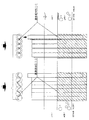
従来技術を示す図1は、従来の軟弱層に支持層をとる水中構造物の造成の際の鋼管矢板1や鋼矢板5による仮締め切りや、恒久構造物として地中に構築する井筒基礎などの施工が行われる際の一般的な断面である。
従来技術を示す図2は、従来の方法の中でも硬質地盤や岩盤3から成る原地盤を支持層とする際に、岩盤を先行して図示しない硬質地盤用オールケーシング工やアースオーガ工による鋼管矢板断面を包摂する円周よりも大径で先行する置換掘削が行われた後に鋼管矢板1や鋼矢板5が打設され、鋼管矢板1による壁体11、鋼矢板5による壁体12が打設されている平面および断面の状況を図示したものである。
FIG. 1 which shows a prior art is a temporary deadline by the steel
FIG. 2 showing the prior art shows a cross section of a steel pipe sheet pile by an all casing or ground auger for hard ground that is not shown in advance when the base is composed of hard ground or
従来方法においては、既置換部が壁体11、壁体12に見られるように大きな範囲で行われ、鋼管矢板1や(特に)鋼矢板5で形成する壁体11、12の前面すなわち流水13が壁体に当たる部分に既置換部が大きいため、少なくとも原地盤の固結性は失われ、結果として二次洗掘の原因となるような緩みを生じていた。
In the conventional method, the replacement part is performed in a large range so that the wall 11 and the wall 12 can be seen, and the front surface of the walls 11 and 12 formed by the steel
本発明においては、まず図3に見られるように鋼管矢板の中空を有する管状杭であるという特性を利用して、鋼管矢板本管外径よりも小口径で先行掘削を行う。
その際、一般的に行われるように硬質地盤用オールケーシング工により置換掘削を行い良質土で構成される本管内既置換部15を設けておくことも可能であり、また図14の態様による掘削装置の構成で、図15のような装置を用いることにより、掘削作業に鋼管矢板圧入作業を追随させ、同時進行させてもよい。
また、大きな貫入抵抗が生ずる場合は、継手部打設位置に既置換部15’を設けておくこともでき、土質に応じて本管内既置換部15、継手部既置換部15’を利用して鋼管矢板圧入をすることができる。
In the present invention, as shown in FIG. 3, first, the excavation is performed with a smaller diameter than the outer diameter of the main pipe sheet pile main pipe, utilizing the characteristic of being a tubular pile having a hollow steel sheet pile.
At that time, as is generally done, it is possible to provide a
In addition, when a large penetration resistance occurs, a
その後、鋼管矢板1を例えば周公知の油圧圧入機を利用して原地盤に打ち込めば、固結性が高い、もしくは玉石、転石等の硬質障害物を多く含む貫入抵抗の大きい地盤にも、圧入される鋼管矢板内空部に設けた比較的固結性の少ない既置換部15に、鋼管矢板1の圧入で押しのけられた土砂が移動する余裕があるため、鋼管矢板は原地盤の必要な固結性を損なうことなく地盤に貫入させることが可能となり、堅固な壁体14を構成することができる。
Then, if the steel
このような方法は、従来洗掘防止に多く用いられてきた鋼矢板5のような中空部を持たない板状構造物では達成することができず、既置換部が流水のあたる外壁側に生ずるため、そこに二次洗掘が生じ、結果として流水対策工が応急措置とならざるを得なかったものである。
Such a method cannot be achieved with a plate-like structure having no hollow portion, such as the
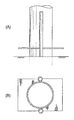
更に、上記鋼管矢板1による壁体14は、従来の鋼管矢板井筒基礎や、鋼管矢板による仮締め切り同様、井筒状態に構造物基礎部を囲繞する閉領域を形成する井筒断面14’を有する壁体とすることができ、その堅牢性を確保することができる。
Furthermore, the
上記構造物基礎部を囲繞する場合には、鋼管矢板壁体の形成する井筒断面14’そのものを外郭16とすること及び、鋼管矢板壁体の形成する井筒断面14’の内側に離隔を有する外郭17のような構造物基礎部を囲繞することを設計上選択することが可能である。
When surrounding the structure base, the well
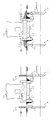
このような構造をもってすれば、硬質地盤、岩盤9上に十分に貫入されずに構築された既設の旧橋脚18のフーチングの基礎部を構成するケーソン21(その内側には地盤面に接地する位置の底面に均しコンクリート20、その上部にフーチングコンクリート19が打設されている)が洗掘された部分22に通常行われている岩ズリ23等の投入によるマウンド状の被覆24で行われる一時的な防護措置とは異なり、十分な強度を有する壁体14によりケーソン21周囲を囲繞し、壁体14が支持層とする硬質地盤、岩盤層9の本来有する強度を生かして、洗掘された部分へのコンクリート打設等の措置を講じて恒久的な洗掘防止等の防護措置が行えると同時に、従来技術の(岩ズリ23等の投入物で生ずる)河積阻害の増大を回避することやそれに伴い損なわれる河川環境、景観を保護することができるという優れた効果を奏することができる。
更に、上記鋼管矢板壁15を水上から打設を完了させた後、鋼管矢板の地盤上の突出部25を周公知の鋼管切断機により切断した後に、将来洗掘が懸念される河床を被覆する護床構造物26、26’を設置する際、該鋼管矢板1、および鋼管矢板壁15の剛性に期待して、突出させた鋼管矢板上端部と護床用構造物を連結する(護床用構造物側にソケット部を設け矢板先端を嵌合させる、護床構造物下部とコンクリート打設により巻き込み一体化する、ボルトナットにより締結する等々による)結合26や、鋼管矢板上端の鋼管矢板本管もしくは鋼管矢板継手部の中空部をソケット部としてそれらに差し込みが自在であるような突出部を護床用構造物下端に設け嵌合させる結合26’等々ができ、鋼管矢板1先端の開口部と内空を利用して堅固な連結構造が確保できるようになる。
この他にも、鋼管矢板1の有する内空部は、河床状態を計測する磁気センサー等の取り付け等、河川監視システムに必要な装置を格納するスペースなどとしても広く利用することが可能となる。
With such a structure, the
Furthermore, after the steel pipe
In addition, the inner space of the steel
また、この壁体14は通水口28を鋼管矢板に設け、地盤上に突出する、従って水中4に突出する鋼管矢板1の一部に通水自在な開口部を設けることにより流過抵抗を利用して壁体の後ろ側に流水を通過させるようにした通水口を安価に確保することが可能となり、加えて、鋼管矢板本管部2や鋼管矢板継手部3に一列欠いた部分(鋼管矢板本管を欠いた部分29、継手部を欠いた部分30)を有する構造とすることにより、水中に突出する部分を予め少なく設計することにより材料についてのコストダウンが図れる。
Further, this
更に、間隙28,29,30を網状構造物31で被覆してスクリーンを設けることにより、鋼管矢板背面にたとえばクラッシャーランなど小さい粒径の充填材を投入しても、外へ流出することを防止することができるようになり、更に、網状構造物の端部に嵌合部を設け、板状にした挿入式スクリーン32の端部鋼管矢板継手との嵌合により確保するようにして、鋼管矢板の継手部(例えばL−L継手3’)を有するという構造上を利用して、鋼管矢板打ち込み完了後に鋼管矢板上面から、挿入すれば簡易且つ、安価に上記スクリーンを設ける構造が得られる。
Furthermore, by covering the
[硬質地盤上の水上構造物基礎の防護構造の施工方法]
続いて、硬質地盤上の水上構造物基礎の防護構造の施工方法について述べる。
[Method of constructing protective structure for floating structure foundation on hard ground]
Then, the construction method of the protection structure of the floating structure foundation on the hard ground is described.
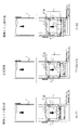
このような硬質地盤上に鋼管矢板14による壁体を構築する上においては、壁体を構成する鋼管矢板の打設に際して硬質地盤9に対しては先の既置換部15、15’のような掘削を行う際に、本発明によればその掘削に図14、15のような方法を用いて、ダウンザホールハンマを用いることにより、確実に硬質地盤の掘削を行え、また掘削と鋼管矢板の圧入を同時並行的に進行させることができる。
In constructing a wall body made of steel pipe sheet piles 14 on such a hard ground, when the steel pipe sheet pile constituting the wall body is placed, the
その態様は以下の様なものである。
ダウンザホールハンマ35およびそれを先端に装着した掘削軸部材34とそれを回転させる回転駆動装置33からなる掘削装置 およびその掘削軸部材33外側に装着された鋼管矢板1は、既設橋脚の維持・補修工事を行うための河川内へアクセスするための工事用道路と、その後の鋼管矢板打設等の作業用構台として設けられた桟橋42上にあるクローラクレーン37により懸垂されている。
The aspect is as follows.
An excavator comprising a down-the-
背後にはダウンザホールハンマ35を駆動する圧搾空気を生成するコンプレッサ39と回転駆動装置の動力源である発動発電機が設置され、コンプレッサ39で生成した圧搾空気はレシーバタンクに集結し、潤滑油供給装置よりハンマ潤滑油を適宜注入しながら高圧エアホースを介して回転駆動装置33を経由し、掘削軸部材34内を通り、ダウンザホールハンマ35に供給され、掘削が行われる。
河川内の杭心位置には、鋼管矢板1が設計位置に打設できるように予め導材43が設けられており、クローラクレーン37は掘削装置を導材43にて確保された設計位置に垂下し、ダウンザホールハンマ35による掘削と鋼管矢板の打設を行う。
A
A guide material 43 is provided in advance at the pile core position in the river so that the steel
鋼管矢板1の打設に際しては、特願2000-157847記載の方法により、 1)鋼管矢板1の打設前に既置換部15,15’を設けておき、その後鋼管矢板を圧入すること、また 2)鋼管矢板1の圧入と掘削作業を同時に行うことが可能となっている。
When placing the steel
すなわち、ダウンザホールハンマ35を用いた掘削では、打撃破砕の進行に伴って該ハンマが掘進するように、孔壁保護管、もしくは鋼管矢板1といった内空部を有するパイプ類の下端部には内空部に突出する段部47を設けられておき、ダウンザホールハンマ35の掘削ビット44の上部には鋼管内壁側へ突出するように段部45を設け、ダウンザホールハンマを鋼管矢板本管2に挿入して、ダウンザホールハンマ35の掘削を行う際に、打撃破砕による掘削の進行に伴って掘削装置が沈降する際、上記掘削ビット44の段部45と上記パイプ類の段部とが干渉して、掘進方向へ掘削に追随して圧入させることができる。
That is, in the excavation using the down-the-
このような方法により、特にパイプ類を鋼管矢板1とすることで、硬質地盤や岩盤で構成される原地盤に対して掘削と鋼管矢板の圧入工程を同時並行化することができ、従って、河川内施工や災害復旧時の急速施工に対応するスピーディーな施工を実施することができる。
更に図14、15記載の機械構成は、継手部の先行掘削にも用いることができ、その際には、掘削ビット、孔壁保護管等は、継手部付近の掘削量を可及的少量にするように、継手部管径とほぼ同径、略等しく下回る径、もしくは略等しく上回る径、継手嵌合部全体を包摂する径の装置を準備して、本管同様に施工を行うことが可能である。
またその際、継手部と本管部掘削は同時並行で進行させても良い。
By such a method, especially pipes are made of steel
Furthermore, the machine configuration shown in FIGS. 14 and 15 can also be used for preceding excavation of the joint portion. In this case, the excavation bit, the hole wall protection pipe, etc., reduce the excavation amount near the joint portion as much as possible. Thus, it is possible to prepare a device with a diameter that is almost the same as the joint pipe diameter, a diameter that is substantially less than or equal to the pipe diameter, and a diameter that encompasses the entire fitting fitting part, and can be constructed in the same way as the main pipe. It is.
Further, at that time, the joint part and the main part excavation may be performed in parallel.
また、鋼管矢板1の圧入と掘削作業を同時進行させる際に、掘削ビット44の削孔面を形成する外周が鋼管矢板本管2径とほぼ同径のもの46’、略等しく下回る径のもの46、もしくは略等しく上回る径のもの46''のいずれかであるように拡大されるように構成することができ、それによって、比較的貫入しやすい硬質地盤9に対しては、より原地盤の固結性を保護するため小径(鋼管矢板と同径46’、略等しく下回る径46)のダウンザホールハンマの掘削ビットによる掘削を行い鋼管矢板が貫入する際の圧密硬化により原地盤を更に締め固めることができるようにするとともに、貫入抵抗が増大することが懸念され且つ掘削後の固結性に十分期待できる岩盤層では、施工性を重視し、鋼管矢板本管よりも略上回る径46’’で施工を行い、急速施工を選択することが可能となる。
Further, when the press fitting of the steel
また、掘削対象の地盤によっては、低騒音、低振動の施工を行うために油圧式圧入機による施工を行うことができ、その際圧入の抵抗が大きい場合には、鋼管矢板本管2内空部を排土経路として掘削ずりを排出する際に、掘削ずり格納部を有する排土装置(たとえば図17に示すようなスクリュードライバー(中掘り装置)49)を利用して、断続的に掘削ずりを引き上げるようにする。 In addition, depending on the ground to be excavated, it is possible to perform construction with a hydraulic press machine in order to perform low noise and low vibration construction. When discharging excavation shear using the section as a soil discharge path, the excavation shear is intermittently made using a soil removal device (for example, a screw driver (medium excavation device) 49 as shown in FIG. 17) having a excavation storage unit. To raise.
図3に示すスクリュードライバー49は、ワイヤロープを介してクレーンフック56によって吊設されており、スクリュードリル51と、回転駆動装置53と、中空の円筒状カプセルパイプ52と、スクリュードリル用伸縮シリンダ51’と、油圧グリッパ54と、グリッパ用伸縮シリンダ55とを有している。
The
上記スクリュードライバー49において、スクリュードリル51は、その先端に地盤を掘削するためのドリルヘッド50を備えており、当該スクリュードリル51を回転駆動させるための回転駆動装置53に連結されている。カプセルパイプ52は、スクリュードリル51の周囲を覆うように設けられ、当該スクリュードリル51によって掘削された掘削ずりを内側に一時的に格納することができるように構成されている。
In the
スクリュードリル用伸縮シリンダ51’は、スクリュードリル51に連結されており、当該スクリュードリル51を自在に昇降できるように伸縮自在に構成されている。油圧グリッパ54は、張り出した状態において、鋼管矢板本管2の内壁に対して、回転圧入掘削に必要な回転圧入反力を確保できるようになっている。グリッパ用伸縮シリンダ55は、油圧グリッパ52に連結されており、当該油圧グリッパ52を自在に張り出すことができるように伸縮自在に構成されている。
また、鋼管矢板の内部を掘削し水中および地中に中空部を確保すれば、そのスペースを利用して、例えば、磁気センサーなどの洗掘監視装置57等を設置することも可能であり、更に、管内を貯水58やその他の凍結防止剤などの多目的の格納スペースとして利用することも可能である。
The screw drill telescopic cylinder 51 ′ is connected to the screw drill 51 and is configured to be telescopic so that the screw drill 51 can be moved up and down freely. The hydraulic gripper 54 can secure a rotational press-fitting reaction force necessary for the rotary press-fitting excavation with respect to the inner wall of the steel pipe sheet pile
If the inside of the steel pipe sheet pile is excavated and a hollow portion is secured in the water and in the ground, it is possible to use the space to install, for example, a scour monitoring device 57 such as a magnetic sensor. It is also possible to use the inside of the pipe as a multipurpose storage space such as the
最後に鋼管矢板1が打ち込まれると、図18のように、中掘掘削を併用している場合にはコンクリート系材料を用いて鋼管矢板1の先端部を充填し鋼管矢板内外に閉塞状態57を確保することができ、逸水を防止し洗掘など流水の影響を低減することができ、また高い品質を確保するために、周囲の地盤に対して薬液注入等を行うことも自在である。
なお、打設された鋼管矢板の天端位置は自由に選択でき、洗掘防止以外に鋼管矢板に付与する構造上の要件に応じて自由に設計ができるものであり、施工についても既設橋脚下部工補強、新設下部工建設作業の際に当該構造物の周囲の止水のため仮締切り工として、鋼管矢板壁15を利用するなどの施工上の手順も設計上任意に選択できるものである。
Finally, when the steel
The top position of the cast steel sheet pile can be freely selected, and it can be designed freely according to the structural requirements given to the steel sheet pile other than scouring prevention. The construction procedure such as using the steel pipe
[他の実施形態]
1. 洗掘のメカニズム
図19に基づいて、従来の鋼管矢板を水底地盤に打設した場合に予想される洗掘のメカニズムを説明する。
[Other Embodiments]
1. Scouring Mechanism Based on FIG. 19, the scouring mechanism expected when a conventional steel pipe sheet pile is placed on the bottom of the water will be described.
鋼管矢板を水底地盤に打設した場合、上流からの流水が鋼管矢板の前面に当たり、円柱に沿う下向きの流れが生ずる。この下降流は、鋼管矢板前方の地盤上に、図18に示すような回転流(渦)を発生させる。渦を成す回転流は、それに接する河床から砂を次々とピックアップし、河床レベルを低下させる。河床が低下すると渦位置もそれに伴って低下するので、鋼管矢板前方の河床が経時的に洗掘されることとなる。 When the steel pipe sheet pile is driven on the bottom of the ground, the flowing water from the upstream hits the front surface of the steel pipe sheet pile, and a downward flow along the cylinder occurs. This downward flow generates a rotational flow (vortex) as shown in FIG. 18 on the ground in front of the steel pipe sheet pile. The swirling rotating flow picks up sand from the riverbed that touches it and lowers the riverbed level. When the river bed is lowered, the vortex position is lowered accordingly, so that the river bed ahead of the steel pipe sheet pile is scoured with time.
2. 本発明の鋼管矢板
次に、図20に基づいて、洗掘防止機能を備えた本発明の杭材について説明する。以下、杭材の例として鋼管矢板を挙げる。
2. Next, based on FIG. 20, the pile material of the present invention having a scouring prevention function will be described. Hereinafter, a steel pipe sheet pile is mentioned as an example of a pile material.
杭材の一例である鋼管矢板は、図20に示すように、鋼管から成る本管と、該本管に固設された2つの継手と、鋼管矢板周囲の水流を制御するためのプレート(水流制御手段)と、を有している。鋼管矢板を隣接する鋼管矢板に連結させる際には、各鋼管矢板の継手を互いにスライド係合させる。水流制御手段を成すプレートは、図20(B)に示すように鋼管矢板周囲に張り出した鍔状に形成されている。鍔状のプレートは、鋼管矢板の外壁に沿う下向きの水流を遮って、洗掘の一因である回転流が発生するのを防止する。したがって、流水の影響から鋼管矢板を防護できる。 As shown in FIG. 20, a steel pipe sheet pile as an example of a pile material includes a main pipe made of a steel pipe, two joints fixed to the main pipe, and a plate for controlling the water flow around the steel pipe sheet pile (water flow). Control means). When connecting a steel pipe sheet pile to an adjacent steel pipe sheet pile, a joint of each steel pipe sheet pile is slidably engaged with each other. As shown in FIG. 20 (B), the plate constituting the water flow control means is formed in a bowl shape projecting around the steel pipe sheet pile. The bowl-like plate blocks the downward water flow along the outer wall of the steel pipe sheet pile and prevents the generation of a rotating flow that is a cause of scouring. Therefore, the steel pipe sheet pile can be protected from the influence of flowing water.
なお、鍔状のプレートの枚数は、必ずしも1枚に限定されず、図21(A)(B)に示すように複数枚設けてもよい。また、水流制御手段の構成は、鍔状のプレートに限定されず、杭材の外壁から張り出した凸状の部材(たとえばブロック状の部材)であってもよい。また、鋼管矢板の本管の外壁の一部を図22に示すように凹凸状に加工して、当該外壁を水流制御手段として機能させることも可能である。 Note that the number of bowl-shaped plates is not necessarily limited to one, and a plurality of bowl-shaped plates may be provided as shown in FIGS. Moreover, the structure of a water flow control means is not limited to a bowl-shaped plate, The convex-shaped member (for example, block-shaped member) protruded from the outer wall of a pile material may be sufficient. Moreover, it is also possible to process a part of the outer wall of the main pipe sheet pile into an irregular shape as shown in FIG. 22 so that the outer wall functions as water flow control means.
また、鋼管矢板前方で回転流が発生するのを防止するために、鋼管矢板を図23及び図24に示すように構成することも可能である。図23では、鋼管矢板の本管に、通水自在な開口部が形成されている。また、図24では、鋼管矢板の本管に、通水自在なスリットが形成されている。このような開口部及びスリットを、継手に形成してもよい。 Further, in order to prevent a rotating flow from being generated in front of the steel pipe sheet pile, the steel pipe sheet pile can be configured as shown in FIGS. In FIG. 23, the water pipe opening is formed in the main pipe of the steel pipe sheet pile. Moreover, in FIG. 24, the slit which can permeate | transmit water is formed in the main pipe of a steel pipe sheet pile. Such openings and slits may be formed in the joint.
3. 水上構造物を防護するための壁体構造
次に、図25〜図28に基づいて、上述した鋼管矢板を利用した壁体構造について説明する。
3. Next, a wall structure using the above-described steel pipe sheet pile will be described with reference to FIGS. 25 to 28.
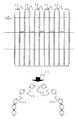
図25に示す壁体は、鋼管矢板を複数連結することによって構成されている。各鋼管矢板は、図20〜図24を参照しながら説明した洗掘防止機能を備えている。複数の鋼管矢板から成る壁体は、水上構造物基礎部(ハッチングで示す)へ向かう水流を遮るように、該水上構造物基礎部と対向して構築されている。 The wall shown in FIG. 25 is configured by connecting a plurality of steel pipe sheet piles. Each steel pipe sheet pile has the scour prevention function described with reference to FIGS. The wall body which consists of a some steel pipe sheet pile is constructed facing this water structure foundation part so that the water flow which goes to a water structure foundation part (it shows by hatching) may be interrupted | blocked.
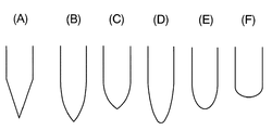
壁体を成す複数の鋼管矢板は、上方から見て略V字を描くように、或いは放物線を描くように配されている。壁体構造のV字状の配置例を、図26(A)〜(C)に示す。また、壁体構造の放物線状の配置例を、図26(D)〜(F)に示す。図25に示すV字状配置の頂部(上流側の先端)に位置する鋼管矢板は、他の杭材よりも上流側に位置している。また、水上構造物基礎部は、頂部の鋼管矢板よりも下流側であって且つ壁体の内側に位置している。このような壁体構造によれば、水上構造物の基礎部を流水の影響から防護することができる。 The plurality of steel pipe sheet piles constituting the wall body are arranged so as to draw a substantially V-shape or a parabola as viewed from above. Examples of the V-shaped arrangement of the wall structure are shown in FIGS. Moreover, the parabolic arrangement | positioning example of a wall structure is shown to FIG.26 (D)-(F). The steel pipe sheet pile located at the top (upstream end) of the V-shaped arrangement shown in FIG. 25 is located upstream of the other pile materials. Moreover, a water structure foundation part is located downstream from the steel pipe sheet pile of a top part, and is located inside a wall body. According to such a wall structure, the foundation of the floating structure can be protected from the influence of flowing water.
なお、基礎部を流水の影響からより確実に防護するためには、図27に示すように、壁体を、水上構造物基礎部の周囲を囲うように構築することが好ましい。また、河川等において、水流方向が一方向に定まっていない場合には、壁体を、図28に示すように構築することが好ましい。 In addition, in order to protect a foundation part more reliably from the influence of flowing water, as shown in FIG. 27, it is preferable to construct | assemble a wall body so that the circumference | surroundings of a water structure foundation part may be enclosed. In addition, in a river or the like, when the water flow direction is not fixed in one direction, it is preferable to construct the wall body as shown in FIG.
このように本発明は、水上構造物一般の新規建設に際しての健全性の確保および、既設構造物の補修とリフレッシュの技術分野において好適に用いられるが、特に、鉄道橋等の古い歴史のある河川構造物およびその支持地盤の保護および、その河川の美化、環境対策工として起用することにより、構造物の安全性を確保し防災対策を強化すると共に、わが国土木構造物の歴史的価値を文化遺産として後世に継承する手段として、広く用いることができるものである。 As described above, the present invention is suitably used in the technical field of ensuring soundness in the new construction of water structures in general and repairing and refreshing existing structures. In particular, rivers with an old history such as railway bridges are used. By protecting the structure and its supporting ground, beautifying the river, and promoting environmental measures, the structure is secured and disaster prevention measures are strengthened, and the historical value of civil engineering structures in Japan is a cultural heritage. It can be widely used as a means to be passed on to future generations.
1 鋼管矢板
2 鋼管矢板本管
3 鋼管矢板継手部
4 従来の鋼管矢板による壁体
5 鋼矢板
6 鋼矢板による壁体
7 水中
8 玉石や転石などの硬質障害物を含まない表層
8’ 玉石や転石などの硬質障害物を含む表層
9 硬質地盤・岩盤
10 置換掘削で既置換部となった先行掘削部
11 既置換部に打設した鋼管矢板による壁体
12 既置換部に打設した鋼矢板による壁体
14 鋼管矢板本管よりも小口径の既置換部を有する地盤に打設された鋼管矢板に
よる壁体
15 鋼管矢板本管よりも小口径の先行掘削部
15’ 鋼管矢板継手部の先行掘削部
16 鋼管矢板井筒から内側に離隔を有して壁面を構成している構造物基礎部
17 鋼管矢板井筒を壁面とした構造物基礎部
18 既設橋脚
19 フーチングコンクリート
20 均しコンクリート
21 ケーソン基礎
22 洗掘部
23 応急対策で設けられた捨石(岩ズリ)マウンド
24 岩ズリ
25 鋼管矢板の切断部
26 護床構造
27 地中で支持層部にまで貫入させた鋼管矢板継手部
28 鋼管矢板にもうけた通水口
29 鋼管矢板本管を1列欠いて設けた通水口
30 鋼管矢板継手部を1列欠いて設けた通水口
31 通水口を被覆する網状構造
32 鋼管矢板の継手部に嵌合自在な板状の網状構造
33 回転駆動装置
34 掘削軸部材
35 ダウンザホールハンマ
36 掘削ビット
37 クローラクレーン
38 発動発電機
39 空気圧縮機
40 レシーバタンク
41 ラインオイラー
42 桟橋
43 導材
44 掘削ビット詳細図
45 掘削ビット段部
46 掘削ビット先端部
47 鋼管矢板段部
48 2つの継手部を包摂する断面径の継手部先行掘削
48’ 1つの継手部を包摂する断面径の継手部先行掘削
48’’ 1つの継手部内空に包摂される断面径の継手部先行掘削
49 スクリュードライバー掘削装置
50 スクリューヘッド
51 スクリュードリル
51’ スクリュードリル用伸縮シリンダ
52 カプセルパイプ
53 圧入シリンダ
54 油圧グリッパ
55 グリッパ用伸縮シリンダ
56 フック
57 洗掘監視用磁気センサ
58 水、他流体
59 根固め材注入部
DESCRIPTION OF
According to the wall 15 The preceding excavation part 15 'of a smaller diameter than the steel pipe sheet pile main pipe The preceding excavation part 16 of the steel pipe sheet pile joint part The structure base part 17 having a wall inwardly separated from the steel pipe sheet pile well Structure foundation 18 with sheet piles as wall surface Existing pier 19 Footing concrete 20 Leveling concrete 21 Caisson foundation 22 Scouring section 23 Rubble (rock sludge) mound 24 provided as an emergency measure 25 Rock shear 25 Cutting section 26 of steel pipe sheet pile Protective floor structure 27 Steel pipe sheet pile joint part penetrated to the support layer part in the ground 28 Water inlet port provided in the steel pipe sheet pile 29 Water inlet part provided with one steel pipe sheet pile main pipe missing One row of steel pipe sheet pile joint parts Water flow port 31 provided to cover the water flow port 32 Plate-like network structure that can be fitted to a joint portion of a steel pipe sheet pile 33 Rotation drive device 34 Excavation shaft member 35 Down-the-hole hammer 36 Digging Bit 37 Crawler crane 38 Motor generator 39 Air compressor 40 Receiver tank 41 Line oiler 42 Pier 43 Guide material 44 Drilling bit detailed view 45 Drilling bit step 46 Drilling bit tip 47 Steel pipe sheet pile step 48 Including two joints Joint section leading excavation 48 ′ having a sectional diameter of a joint section leading section excavation 48 ′ including a joint section Joint section leading excavation of a section diameter included in one joint section 49 Screw driver drilling device 50 Screw Head 51 Screw drill 51 'Expansion cylinder for screw drill 52 Capsule pipe 53 Press-fit cylinder 54 Hydraulic gripper 55 Telescopic cylinder for gripper 56 Hook 57 Magnetic sensor 58 for scouring monitoring Water, other fluid 59 Rooting material injection part
Claims (5)
鋼管矢板よりなる杭材の内壁に段部を設け、
ダウンザホールハンマの掘削ビット上部に段部を設け、
前記原地盤上の杭材打設予定位置に前記杭材をセットし、
前記ダウンザホールハンマを前記杭材に挿入し、該ダウンザホールハンマで中掘掘削を行い、
前記中掘掘削においてダウンザホールハンマが沈降する際、ダウンザホールハンマ側の段部と杭材側の段部とを上下方向で相互干渉させ、それにより、該ハンマによる打撃破砕に追随してその打撃力により杭材が掘進方向へ圧入されるようにし、
前記中掘掘削と打撃によって、前記原地盤に支持されるように前記杭材を打設し、
前記杭材の打設工程を繰り返すことによって、隣接する杭材が連結してなる壁体を前記水上構造物基礎部と対向するように構築する、
ことを特徴とする水上構造物基礎部の防護方法。 The foundations of water structures such as direct foundations and caisson foundations that are supported by shallow parts of the riverbed that are so hard that a pile material cannot be penetrated by a vibratory hammer or hydraulic press machine are washed by running river water. In a method to protect against digging,
A step is provided on the inner wall of the pile material made of steel pipe sheet piles,
A step is provided at the top of the drill bit of the down-the-hole hammer,
Set the pile material at the planned pile material placement position on the raw ground,
Insert the down-the-hole hammer into the pile material, perform excavation with the down-the-hole hammer,
When the down-the-hole hammer settle in drilling drilling in the, and the step portion of the down-the-hole hammer side and pile material side is interference in the vertical direction, whereby, due to the striking force to follow the strike breaking by the hammer Make sure that the pile material is pressed in the direction of excavation,
The pile material is driven so as to be supported by the original ground by the excavation and hammering ,
By repeating the placing process of the pile material, a wall body formed by connecting adjacent pile materials is constructed so as to face the water structure foundation.
A method for protecting the foundation of a floating structure characterized by the above.
前記略V字状配置又は放物線配置の頂部に位置する杭材を、他の杭材よりも上流側に位置決めし、
前記水上構造物基礎部が前記頂部の杭材よりも下流側に位置するように、前記壁体を構築する、
ことを特徴とする請求項1記載の水上構造物基礎部の防護方法。 Positioning all or a part of the plurality of pile members constituting the wall body so as to draw a substantially V-shaped or parabola when viewed from above,
The pile material located at the top of the substantially V-shaped arrangement or the parabolic arrangement is positioned upstream of the other pile materials,
Constructing the wall so that the water structure foundation is located downstream of the pile material at the top,
The method for protecting a water structure foundation according to claim 1.
Priority Applications (1)
| Application Number | Priority Date | Filing Date | Title |
|---|---|---|---|
| JP2005170703A JP4875318B2 (en) | 2005-06-10 | 2005-06-10 | Protection method for the foundation of floating structures |
Applications Claiming Priority (1)
| Application Number | Priority Date | Filing Date | Title |
|---|---|---|---|
| JP2005170703A JP4875318B2 (en) | 2005-06-10 | 2005-06-10 | Protection method for the foundation of floating structures |
Publications (3)
| Publication Number | Publication Date |
|---|---|
| JP2006342614A JP2006342614A (en) | 2006-12-21 |
| JP2006342614A5 JP2006342614A5 (en) | 2008-07-17 |
| JP4875318B2 true JP4875318B2 (en) | 2012-02-15 |
Family
ID=37639774
Family Applications (1)
| Application Number | Title | Priority Date | Filing Date |
|---|---|---|---|
| JP2005170703A Active JP4875318B2 (en) | 2005-06-10 | 2005-06-10 | Protection method for the foundation of floating structures |
Country Status (1)
| Country | Link |
|---|---|
| JP (1) | JP4875318B2 (en) |
Cited By (1)
| Publication number | Priority date | Publication date | Assignee | Title |
|---|---|---|---|---|
| CN104328794A (en) * | 2014-11-04 | 2015-02-04 | 国家电网公司 | Narrow-base-tower four-leg combined sunk well foundation |
Families Citing this family (11)
| Publication number | Priority date | Publication date | Assignee | Title |
|---|---|---|---|---|
| JP6007036B2 (en) * | 2012-09-09 | 2016-10-12 | 株式会社横山基礎工事 | Steel pipe sheet pile placing method |
| JP6262433B2 (en) * | 2013-02-05 | 2018-01-17 | 中国電力株式会社 | Steel tower protective work |
| JP2014194122A (en) * | 2013-03-28 | 2014-10-09 | Kubota Corp | Method for forming steel pipe sheet pile foundation, and steel pipe sheet pile foundation |
| JP6537778B2 (en) * | 2014-03-27 | 2019-07-03 | 株式会社横山基礎工事 | Environmental load reduction device and construction method |
| KR101644234B1 (en) * | 2014-08-29 | 2016-07-29 | 삼보씨엠씨 주식회사 | The excavation method for submarine ground |
| JP6943633B2 (en) * | 2017-06-01 | 2021-10-06 | 株式会社横山基礎工事 | Ring-shaped tip hardware and middle digging pile method using it |
| JP2019007132A (en) * | 2017-06-20 | 2019-01-17 | 清水建設株式会社 | Construction method of steel pipe sheet pile well foundation |
| JP6951956B2 (en) * | 2017-12-07 | 2021-10-20 | 五洋建設株式会社 | Groyne |
| JP7162552B2 (en) * | 2019-02-22 | 2022-10-28 | 清水建設株式会社 | Diameter expansion device and diameter expansion method |
| CN113186889B (en) * | 2021-02-02 | 2023-01-17 | 中国海洋大学 | Combined pile plate structure for reinforcing and protecting artificial reef and construction method thereof |
| CN113529590B (en) * | 2021-09-06 | 2023-04-28 | 水利部交通运输部国家能源局南京水利科学研究院 | Multistage cushion protection method capable of slowing down local scour of pier foundation |
Family Cites Families (7)
| Publication number | Priority date | Publication date | Assignee | Title |
|---|---|---|---|---|
| BE898209A (en) * | 1982-11-10 | 1984-03-01 | Gulf Applied Tech | Erosion control method and device. |
| JPS61134409A (en) * | 1984-12-01 | 1986-06-21 | Nippon Solid Co Ltd | Method of preventing scouring of underwater structure |
| JP2860396B2 (en) * | 1993-06-11 | 1999-02-24 | 運輸省港湾技術研究所長 | Water sheet pile wall structure with a slit for wave dissipation on top |
| JP3165997B2 (en) * | 1996-05-14 | 2001-05-14 | 鹿島建設株式会社 | Casting method and equipment for sheet piles |
| JP2972853B2 (en) * | 1996-10-14 | 1999-11-08 | 旭エンジニアリング株式会社 | Steel pipe arrangement hole forming apparatus and steel pipe sheet pile forming method |
| JP2004232436A (en) * | 2003-02-03 | 2004-08-19 | Ohbayashi Corp | Pier foundation reinforcing method and pier foundation reinforcing structure |
| JP4281567B2 (en) * | 2004-02-13 | 2009-06-17 | 株式会社大林組 | Reinforcement structure of existing pier foundation and reinforcement method of existing pier foundation |
-
2005
- 2005-06-10 JP JP2005170703A patent/JP4875318B2/en active Active
Cited By (1)
| Publication number | Priority date | Publication date | Assignee | Title |
|---|---|---|---|---|
| CN104328794A (en) * | 2014-11-04 | 2015-02-04 | 国家电网公司 | Narrow-base-tower four-leg combined sunk well foundation |
Also Published As
| Publication number | Publication date |
|---|---|
| JP2006342614A (en) | 2006-12-21 |
Similar Documents
| Publication | Publication Date | Title |
|---|---|---|
| Smoltczyk | Geotechnical Engineering Handbook, Procedures | |
| US6139225A (en) | Method for building an underground continuous wall | |
| JP4875318B2 (en) | Protection method for the foundation of floating structures | |
| CN107859145A (en) | A kind of drainpipe is plugged into construction method under water | |
| CN110359476A (en) | A kind of construction method of steel sheet-pile cofferdam inner support and drilled pile steel pile casting installation operation platform | |
| JP6319935B2 (en) | Tubing pile driving method | |
| CN108755719A (en) | Seabed municipal tunnel over strait cofferdam open cutting construction method | |
| JP3967473B2 (en) | Construction method of underground structure | |
| JP2008019561A (en) | Construction method of countermeasure against liquefaction under breakwater caused by creation of underground wall | |
| Spagnoli et al. | Trench cutter case histories and their possible application for offshore piles as relieve drilling | |
| JPH08184058A (en) | Landslide protection construction | |
| Milanovic | Prevention and remediation in karst engineering | |
| KR101074881B1 (en) | cut-off wall using sheet pile working method | |
| JP4845537B2 (en) | Pile driving method for underwater structures | |
| Spagnoli et al. | Support for offshore monopile installation through the trench cutter technology | |
| JPH0470422A (en) | Open caisson method | |
| JP7566235B1 (en) | Ground improvement methods | |
| JP2976390B2 (en) | Method for preventing liquefaction of the foundation directly under the existing structure | |
| Bruce et al. | Rehabilitation of Beaver Dam: A major seepage cut-off wall | |
| JP2014109190A (en) | Foot protection method for steel pile | |
| JP7248545B2 (en) | Construction method of drilling rig and monopile foundation | |
| JP2014109143A (en) | Foot protection method for steel pile | |
| CN111705806B (en) | Underwater earth and rockfill excavation method for foundation pits in deep water area | |
| TW201016930A (en) | Regulation method for river with the function of protecting bridge pier and dike, and with the function of forming sand and stone collecting specific area | |
| De Roubaix | Big challenges at Small Bay |
Legal Events
| Date | Code | Title | Description |
|---|---|---|---|
| A521 | Request for written amendment filed |
Free format text: JAPANESE INTERMEDIATE CODE: A523 Effective date: 20080530 |
|
| RD02 | Notification of acceptance of power of attorney |
Free format text: JAPANESE INTERMEDIATE CODE: A7422 Effective date: 20080530 |
|
| A621 | Written request for application examination |
Free format text: JAPANESE INTERMEDIATE CODE: A621 Effective date: 20080605 |
|
| A977 | Report on retrieval |
Free format text: JAPANESE INTERMEDIATE CODE: A971007 Effective date: 20091116 |
|
| RD04 | Notification of resignation of power of attorney |
Free format text: JAPANESE INTERMEDIATE CODE: A7424 Effective date: 20100330 |
|
| RD02 | Notification of acceptance of power of attorney |
Free format text: JAPANESE INTERMEDIATE CODE: A7422 Effective date: 20100415 |
|
| A131 | Notification of reasons for refusal |
Free format text: JAPANESE INTERMEDIATE CODE: A131 Effective date: 20100514 |
|
| RD13 | Notification of appointment of power of sub attorney |
Free format text: JAPANESE INTERMEDIATE CODE: A7433 Effective date: 20100524 |
|
| A521 | Request for written amendment filed |
Free format text: JAPANESE INTERMEDIATE CODE: A523 Effective date: 20100713 |
|
| A131 | Notification of reasons for refusal |
Free format text: JAPANESE INTERMEDIATE CODE: A131 Effective date: 20110223 |
|
| A521 | Request for written amendment filed |
Free format text: JAPANESE INTERMEDIATE CODE: A523 Effective date: 20110422 |
|
| RD14 | Notification of resignation of power of sub attorney |
Free format text: JAPANESE INTERMEDIATE CODE: A7434 Effective date: 20110531 |
|
| A131 | Notification of reasons for refusal |
Free format text: JAPANESE INTERMEDIATE CODE: A131 Effective date: 20110802 |
|
| A521 | Request for written amendment filed |
Free format text: JAPANESE INTERMEDIATE CODE: A523 Effective date: 20110909 |
|
| TRDD | Decision of grant or rejection written | ||
| A01 | Written decision to grant a patent or to grant a registration (utility model) |
Free format text: JAPANESE INTERMEDIATE CODE: A01 Effective date: 20111116 |
|
| A01 | Written decision to grant a patent or to grant a registration (utility model) |
Free format text: JAPANESE INTERMEDIATE CODE: A01 |
|
| A61 | First payment of annual fees (during grant procedure) |
Free format text: JAPANESE INTERMEDIATE CODE: A61 Effective date: 20111125 |
|
| FPAY | Renewal fee payment (event date is renewal date of database) |
Free format text: PAYMENT UNTIL: 20141202 Year of fee payment: 3 |
|
| R150 | Certificate of patent or registration of utility model |
Ref document number: 4875318 Country of ref document: JP Free format text: JAPANESE INTERMEDIATE CODE: R150 Free format text: JAPANESE INTERMEDIATE CODE: R150 |
|
| R250 | Receipt of annual fees |
Free format text: JAPANESE INTERMEDIATE CODE: R250 |
|
| R250 | Receipt of annual fees |
Free format text: JAPANESE INTERMEDIATE CODE: R250 |
|
| R250 | Receipt of annual fees |
Free format text: JAPANESE INTERMEDIATE CODE: R250 |
|
| R250 | Receipt of annual fees |
Free format text: JAPANESE INTERMEDIATE CODE: R250 |
|
| R250 | Receipt of annual fees |
Free format text: JAPANESE INTERMEDIATE CODE: R250 |
|
| R250 | Receipt of annual fees |
Free format text: JAPANESE INTERMEDIATE CODE: R250 |
|
| R250 | Receipt of annual fees |
Free format text: JAPANESE INTERMEDIATE CODE: R250 |
|
| R250 | Receipt of annual fees |
Free format text: JAPANESE INTERMEDIATE CODE: R250 |
|
| R250 | Receipt of annual fees |
Free format text: JAPANESE INTERMEDIATE CODE: R250 |
|
| R250 | Receipt of annual fees |
Free format text: JAPANESE INTERMEDIATE CODE: R250 |