JP4874296B2 - Ship rudder - Google Patents
Ship rudder Download PDFInfo
- Publication number
- JP4874296B2 JP4874296B2 JP2008157505A JP2008157505A JP4874296B2 JP 4874296 B2 JP4874296 B2 JP 4874296B2 JP 2008157505 A JP2008157505 A JP 2008157505A JP 2008157505 A JP2008157505 A JP 2008157505A JP 4874296 B2 JP4874296 B2 JP 4874296B2
- Authority
- JP
- Japan
- Prior art keywords
- rudder
- ship
- plate
- fin
- hull
- Prior art date
- Legal status (The legal status is an assumption and is not a legal conclusion. Google has not performed a legal analysis and makes no representation as to the accuracy of the status listed.)
- Expired - Fee Related
Links
Images


Classifications
-
- B—PERFORMING OPERATIONS; TRANSPORTING
- B63—SHIPS OR OTHER WATERBORNE VESSELS; RELATED EQUIPMENT
- B63H—MARINE PROPULSION OR STEERING
- B63H25/00—Steering; Slowing-down otherwise than by use of propulsive elements; Dynamic anchoring, i.e. positioning vessels by means of main or auxiliary propulsive elements
- B63H25/06—Steering by rudders
- B63H25/38—Rudders
- B63H25/381—Rudders with flaps
Landscapes
- Engineering & Computer Science (AREA)
- Combustion & Propulsion (AREA)
- Mechanical Engineering (AREA)
- Ocean & Marine Engineering (AREA)
- Chemical & Material Sciences (AREA)
- Vibration Prevention Devices (AREA)
- Toys (AREA)
- Physical Or Chemical Processes And Apparatus (AREA)
- Prevention Of Electric Corrosion (AREA)
- Catching Or Destruction (AREA)
- Farming Of Fish And Shellfish (AREA)
- Revetment (AREA)
- Soil Working Implements (AREA)
- Medicines Containing Material From Animals Or Micro-Organisms (AREA)
- Mechanical Control Devices (AREA)
- Other Liquid Machine Or Engine Such As Wave Power Use (AREA)
- Wind Motors (AREA)
- Steroid Compounds (AREA)
Abstract
Description
本発明は、請求項1の上位概念に記載した船舶用舵に関するものである。
The present invention relates to a marine rudder described in the superordinate concept of
特許文献1には船舶用の舵が開示されており、この舵は、船体の下方に設けられ、かつ、舵シャフトを有する舵板と、該舵板に回動可能に結合されたフィンとを備えて構成されている。ここで、フィンは制御要素を備えており、舵板は胴軸受によって支持されている。
しかしながら、上記特許文献1における舵においては、フィンの制御要素が圧力、衝突又は衝撃から保護されていないという問題がある。
However, the rudder in
本発明はこのような問題にかんがみてなされたもので、その目的とするところは、フィンの制御要素を圧力、衝突又は衝撃から保護することが可能な舵を提供することにある。 The present invention has been made in view of these problems, and an object of the present invention is to provide a rudder capable of protecting fin control elements from pressure, collision or impact.
上記目的は、請求項1記載の特徴を有する舵によって達成される。
The object is achieved by a rudder having the features of
本発明の保護部材によれば、フィンの制御要素を外部からの影響から効果的かつ容易に保護することが可能である。また、衝突又は衝撃が保護部材によって実際に受け止められるため、フィンの制御要素が損傷することがない。 According to the protective member of the present invention, it is possible to effectively and easily protect the fin control element from the influence from the outside. Further, since the collision or impact is actually received by the protective member, the fin control element is not damaged.
さらに、保護部材は案内要素として水流を案内する役目を担っており、本発明の一実施形態は、保護部材をガイドプレート又はスポイラとして形成したことを特徴としている。ここで、これらを特に船体の一部に固定するのが好ましい。そして、このような実施形態によれば、推進プロペラからの水流が制御要素の傍らを通過し、その際、この制御要素の近傍における渦の発生を抑制することが可能である。 Furthermore, the protective member plays a role of guiding the water flow as a guide element, and one embodiment of the present invention is characterized in that the protective member is formed as a guide plate or a spoiler. Here, it is particularly preferable to fix them to a part of the hull. And according to such embodiment, the water flow from a propulsion propeller passes along the side of a control element, and it is possible to suppress generation | occurrence | production of the vortex in the vicinity of this control element in that case.
また、保護部材近傍では、推進プロペラによって非常に高い圧力が発生するため、保護部材を船体に固着させるのが望ましい。そうすることによって、渦形成が最小限に抑えられ、推進プロペラによる高圧発生時に保護部材(ガイドプレート)によって舵特性に悪影響が生じるのを防止することができる。 Further, in the vicinity of the protective member, a very high pressure is generated by the propeller, so it is desirable to fix the protective member to the hull. By doing so, vortex formation is minimized, and it is possible to prevent the rudder characteristics from being adversely affected by the protective member (guide plate) when a high pressure is generated by the propeller.
このような効果は、保護部材を水流の妨げとならないよう湾曲させて形成することによって更に高められる。したがって、舵周辺での渦形成が最小限に抑えられ、船舶の航行特性も向上させることが可能である。 Such an effect can be further enhanced by forming the protective member so as not to obstruct the water flow. Therefore, vortex formation around the rudder can be minimized and the navigation characteristics of the ship can be improved.
また、コストの削減を図ることができる固定手段は保護部材をL字状に形成し、その第1の面及び第2の面をそれぞれ固定面及び案内面として形成することである。このように直角に曲げられた保護部材は、その固定面で船体に例えば溶接すればよい。比較的大きな固定面とすることで溶接点が増え、安定した固定が達成される。 Further, the fixing means that can reduce the cost is to form the protective member in an L shape, and to form the first surface and the second surface as a fixed surface and a guide surface, respectively. The protective member bent at a right angle in this way may be welded to the hull, for example, on its fixed surface. By using a relatively large fixing surface, the number of welding points increases, and stable fixing is achieved.
また、本発明の一実施形態は、支持部を胴軸受として形成されたカラー軸受とするとともに、該カラー軸受を、その一端で前記船体に固定し、かつ、内部に舵シャフトを収容する穴を備える構成としたことを特徴としている。こうすることにより、安定した信頼性の高い構造を得ることが可能である。 One embodiment of the present invention is a collar bearing formed as a trunk bearing as a support portion, and the collar bearing is fixed to the hull at one end thereof, and a hole for accommodating the rudder shaft is provided inside. It is characterized by having a configuration provided. By doing so, it is possible to obtain a stable and highly reliable structure.
ところで、フィンは、基本的には舵板の動きに合わせて動作し、舵板と反対方向へ回動するようになっている。一方、本発明の一実施形態は、フィン制御装置を、フィンを舵板の動作と無関係に制御するように構成したことを特徴としている。こうすることで、例えば非常に迅速な方向転換を行うことが可能である。すなわち、舵に対するフィンの慣性が小さいため、迅速な方向転換がなされることになる。 By the way, the fin basically operates in accordance with the movement of the rudder plate and rotates in the direction opposite to the rudder plate. On the other hand, one embodiment of the present invention is characterized in that the fin control device is configured to control the fins independently of the operation of the steering plate. In this way, it is possible to change direction very quickly, for example. That is, since the inertia of the fin with respect to the rudder is small, the direction is quickly changed.
また、フィンを油圧式調整手段又は他の装置によって動作させれば、本発明による保護部材が最適な効果を発揮することになる。 Further, if the fin is operated by a hydraulic adjustment means or other device, the protective member according to the present invention exhibits the optimum effect.
なお、本発明の他の実施形態は、従属請求項に記載されている。 Note that other embodiments of the invention are described in the dependent claims.
以下に本発明の実施の形態を添付図面に基づいて説明する。 Embodiments of the present invention will be described below with reference to the accompanying drawings.
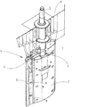
図1aには本発明による船舶用の舵1が示されており、この舵1は、舵板2及び該舵板2に取り付けられたフィン3を含んで構成されている。この舵板2はその高さ方向に沿ってフィン3とヒンジ状に結合されており、複数のヒンジ結合部8を少なくとも1つのヒンジピンが貫通している。
FIG. 1 a shows a
舵1あるいは舵板2は、例えば胴軸受のような公知手段によって支持部4で回動可能に支持されている。したがって、舵板2は、船体6から舵板2内へ延設された舵シャフト5回りに回動可能となっている。
The
しかして、舵板2は、懸垂式となっており、図2に示すように特に円すい状連結部7を備えた構成となっている。なお、この図2に示されている舵1は、いわゆる平衡舵として形成されている。
Therefore, the
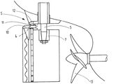
さらに、舵1は制御要素を含んで構成されたフィン制御装置Sを備えており、このフィン制御装置Sは、舵板2の外部のこの舵板2と船体6の間における支持部4近傍に設けられている。
Further, the
ここで、フィン制御装置Sは、フィン3を舵板2の移動(回動)方向と逆方向に回動させるものである。そのため、操船(操舵)時には、舵1が湾曲するような状態となり、良好な操舵作用が発揮されることになる。また、フィン制御装置Sは、フィンブラケット10と、船体ブラケット12と、前記フィンブラケット10の回動させるための連結ピン11とで構成されている。そして、フィンブラケット10を連結ピン11の所定領域に固定することによって所望なフィンの動作が得られるようになっている。
Here, the fin control device S rotates the
なお、図3に示すように、推進プロペラ13が船体17下方において船体17と舵1の間の舵1近傍に設けられているため、舵1には、船舶の航行中に強い水流が作用することになる。
As shown in FIG. 3, since the
ところで、本発明によれば、船体部分、特に船体自体には、制御要素の側方部において保護部材Lが取り付けられている。特に、図示のように、各側方部に保護部材Lを設けることによってフィン制御装置Sを覆うのが望ましい。なお、この保護部材Lをガイドプレート又はスポイラとして形成し、船体の一部あるいは船体に設けることによって固定するのが望ましい。この保護部材Lは、制御要素が例えば圧力又は衝撃によって損傷しないようにするためのものである。 Meanwhile, according to the present invention, hull, especially the hull itself, the protective member L is attached at the side portion of the control element. In particular, as shown in the drawing, it is desirable to cover the fin control device S by providing a protective member L on each side part. The protective member L is preferably formed as a guide plate or a spoiler and fixed by being provided on a part of the hull or on the hull. The protective member L is intended to allow the control element, for example, not damaged by the pressure or impact.
また、保護部材Lを図3に示すように水流に合わせて湾曲させることも可能である。例えば、この保護部材Lをフィン制御装置Sを囲むように円環状に形成して水流を妨げないようにすることも可能である。これにより、渦形成が抑制されて高い効率を得ることができる。 Moreover, it is also possible to curve the protection member L according to a water flow as shown in FIG. For example, the protection member L may be formed in an annular shape so as to surround the fin control device S so as not to disturb the water flow. Thereby, vortex formation is suppressed and high efficiency can be obtained.
図1bで示す保護部材Lのように、この保護部材LをL字状に形成してもよく、この場合、保護部材Lは固定面としての第1の面14と、第2の面とを備えて構成されており、これら面は保護板として機能するものである。
Like the protective member L shown in FIG. 1b, this protective member L may be formed in an L shape. In this case, the protective member L has a
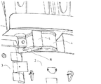
図4及び図5に示されているように、保護部材L(ガイドプレート)は板状でもよく、かつ、比較的短い長さとすることも可能である。また、保護部材Lの下端部を例えば固定された側部ブラケット16に固定することが可能である。なお、図6にはこれを下から見た図が示されている。
As shown in FIGS. 4 and 5, the protection member L (guide plate) may be plate-shaped and may have a relatively short length. Moreover, it is possible to fix the lower end part of the protection member L to the fixed
本発明は、上記例に限定されるものではなく、舵を他の結合形態として構成することも可能である。すなわち、支持部を例えば胴軸受として形成されたカラー軸受とすることもでき、このカラー軸受は、一端で船体に固定され、かつ、内部に舵シャフトを収容する穴を備えている。もちろん、舵の他の形態も可能である。 The present invention is not limited to the above example, and the rudder can be configured as another coupling form. That is, the support portion may be a collar bearing formed as, for example, a trunk bearing, and this collar bearing is fixed to the hull at one end and includes a hole for accommodating the rudder shaft inside. Of course, other forms of rudder are possible.
また、フィン制御装置についても、これを、フィンを舵板の動作と無関係に制御するように構成してもよい。この際、電気的又は油圧による手段を用いることができる。 Moreover, you may comprise this also about a fin control apparatus so that a fin may be controlled irrespective of operation | movement of a steering plate. At this time, electrical or hydraulic means can be used.
さらに、保護部材は、特に船舶が直線的に航行している際の舵板位置において、当該保護部材が舵板の側板と同列あるいは舵板の側板延長部に位置するように配置するのが好ましい。こうすることにより、保護部材と舵板の側板との間の領域で推進プロペラによる渦の発生を防止することが可能である。 Further, the protective member is preferably arranged so that the protective member is located in the same row as the side plate of the rudder plate or in the side plate extension of the rudder plate, particularly at the rudder plate position when the ship is navigating linearly. . By doing so, it is possible to prevent the vortex from being generated by the propeller in the region between the protective member and the side plate of the rudder plate.
1 舵
2 舵板
3 フィン
4 支持部
5 舵シャフト
6 船体
7 円すい状連結部
10 フィンブラケット
11 連結ピン
12 船体ブラケット
13 船舶用推進プロペラ
14 第1の面
15 第2の面
16 側部ブラケット
17 船体
L 保護部材
S フィン制御装置
1
DESCRIPTION OF
Claims (10)
該舵板に結合されたフィン(3)と、
制御要素を備えつつ前記舵板(2)の外部における該舵板と船体(6)の間に設けられたフィン制御装置(S)と
を備えて成る船舶用舵において、
前記制御要素の側方に位置する船体部分に保護部材(L)を設け、該保護部材(L)を、ガイドプレート又はスポイラとして形成するとともに、船体(17)に固着させたことを特徴とする船舶用舵。 A rudder plate (2) rotatably supported by a support portion;
A fin (3) coupled to the rudder blade;
In a ship rudder comprising a fin control device (S) provided between the rudder plate outside the rudder plate (2) and the hull (6) while having a control element,
A protective member (L) is provided on a hull portion located on the side of the control element , and the protective member (L) is formed as a guide plate or a spoiler and is fixed to the hull (17). Ship rudder.
前記船体(6)と前記フィン(3)の間に推進プロペラ(13)を設けたことを特徴とする船舶。 In the ship provided with the rudder according to any one of claims 1 to 9 ,
A ship having a propeller (13) provided between the hull (6) and the fin (3).
Applications Claiming Priority (4)
| Application Number | Priority Date | Filing Date | Title |
|---|---|---|---|
| DE202007008804.3 | 2007-06-21 | ||
| DE202007008804U DE202007008804U1 (en) | 2007-06-21 | 2007-06-21 | Watercraft e.g. ship, rudder, has rudder blade pivotable through bracket, fin controlling device with control units arranged in outer side of blade, and protection conducting units firmly anchored at ship hull |
| EP07023719A EP2006201B1 (en) | 2007-06-21 | 2007-12-07 | Rudder for ships |
| EP07023719.3 | 2007-12-07 |
Publications (2)
| Publication Number | Publication Date |
|---|---|
| JP2009001266A JP2009001266A (en) | 2009-01-08 |
| JP4874296B2 true JP4874296B2 (en) | 2012-02-15 |
Family
ID=38375538
Family Applications (1)
| Application Number | Title | Priority Date | Filing Date |
|---|---|---|---|
| JP2008157505A Expired - Fee Related JP4874296B2 (en) | 2007-06-21 | 2008-06-17 | Ship rudder |
Country Status (16)
| Country | Link |
|---|---|
| US (1) | US8117979B2 (en) |
| EP (1) | EP2006201B1 (en) |
| JP (1) | JP4874296B2 (en) |
| KR (1) | KR101118450B1 (en) |
| CN (1) | CN101327842B (en) |
| AT (1) | ATE447525T1 (en) |
| CY (1) | CY1110641T1 (en) |
| DE (2) | DE202007008804U1 (en) |
| DK (1) | DK2006201T3 (en) |
| ES (1) | ES2335616T3 (en) |
| HK (1) | HK1128013A1 (en) |
| HR (1) | HRP20090644T1 (en) |
| PL (1) | PL2006201T3 (en) |
| PT (1) | PT2006201E (en) |
| SG (1) | SG148919A1 (en) |
| TW (1) | TWI352679B (en) |
Families Citing this family (15)
| Publication number | Priority date | Publication date | Assignee | Title |
|---|---|---|---|---|
| ES2548060T3 (en) * | 2008-09-12 | 2015-10-13 | Wärtsilä Netherlands B.V. | Propulsion and steering arrangement |
| CN101519118B (en) * | 2009-04-17 | 2012-02-01 | 哈尔滨工程大学 | Transmission device of any rotation angle ratio of ship flap rudder of slide block type |
| DE202009009996U1 (en) * | 2009-07-21 | 2010-12-02 | Becker Marine Systems Gmbh & Co. Kg | Finsruder for watercraft |
| DE202010004191U1 (en) * | 2010-03-23 | 2010-07-01 | Van Der Velden Barkemeyer Gmbh | Oars for ships |
| KR101245737B1 (en) * | 2010-11-12 | 2013-03-25 | 삼성중공업 주식회사 | Ship rudder |
| CN102060097B (en) * | 2010-12-14 | 2013-01-16 | 哈尔滨工程大学 | Marine rudder with controllable resistance |
| CN102285442B (en) * | 2011-06-02 | 2014-09-24 | 舟山和达船舶设计有限公司 | Ton-class chemicals helm blade |
| DE102011056001A1 (en) * | 2011-12-02 | 2013-06-06 | FutureShip GmbH | Storage element for semi-balanced rudder provided in rear region of sub ship, has wedge-like profile section including outer profile surface, where plate-like projection expands outer profile surface in transverse direction |
| US8584610B1 (en) | 2013-03-07 | 2013-11-19 | Corning Townsend | Spring loaded geared flap rudder |
| NO336848B1 (en) | 2013-03-08 | 2015-11-16 | Rolls Royce Marine As Rudders | rudder device |
| JP5950971B2 (en) * | 2014-01-06 | 2016-07-13 | ジャパン・ハムワージ株式会社 | Ship rudder |
| CN106956764B (en) * | 2017-04-06 | 2018-10-12 | 中国船舶科学研究中心(中国船舶重工集团公司第七0二研究所) | Protective device for bow elevator rudderpost |
| CN107140152B (en) * | 2017-04-26 | 2019-11-08 | 舟山利远机械有限公司 | A kind of novel rudder system of river sea through transport ship |
| EP3489128A1 (en) * | 2017-11-28 | 2019-05-29 | Becker Marine Systems GmbH | Blade of an oar with modular structure, segment for a blade of an oar for a device for improving propulsion and method for producing a blade of an oar |
| CN115384748A (en) * | 2022-09-15 | 2022-11-25 | 重庆长源船舶设备有限公司 | Suspension type flap rudder for river |
Family Cites Families (10)
| Publication number | Priority date | Publication date | Assignee | Title |
|---|---|---|---|---|
| DE2555098C2 (en) | 1975-12-08 | 1977-10-13 | Willi Becker Ingenieurbüro, 2000 Hamburg | Rudders, in particular balance profile rudders with one fin, for watercraft |
| DE3040808A1 (en) * | 1980-10-30 | 1982-06-03 | Willi Becker Ingenieurbüro GmbH, 2000 Hamburg | OARS, ESPECIALLY HIGH PERFORMANCE, FOR SEA SHIPS |
| JPS60113799A (en) * | 1983-11-26 | 1985-06-20 | Keisebun:Kk | Rudder |
| EP0170919B1 (en) | 1984-07-14 | 1989-10-04 | BARKEMEYER-Schiffstechnik GmbH | High-efficiency flap rudder |
| JPS61150898A (en) * | 1984-12-25 | 1986-07-09 | Keisebun:Kk | Vessel maneuvering device |
| JPS63188596A (en) * | 1987-01-29 | 1988-08-04 | Mitsubishi Heavy Ind Ltd | Hung rudder with radial rudder plate |
| DE8708276U1 (en) | 1987-06-12 | 1987-08-27 | Willi Becker Ingenieurbuero Gmbh, 2000 Hamburg, De | |
| JP3357853B2 (en) | 1998-12-22 | 2002-12-16 | ナカシマプロペラ株式会社 | Double rudder device |
| KR200174861Y1 (en) | 1999-08-02 | 2000-03-15 | 박휴규 | Flap rudder |
| CN2466047Y (en) * | 2000-12-25 | 2001-12-19 | 宋泉发 | Flap rudder transmission |
-
2007
- 2007-06-21 DE DE202007008804U patent/DE202007008804U1/en not_active Expired - Lifetime
- 2007-12-07 PT PT07023719T patent/PT2006201E/en unknown
- 2007-12-07 AT AT07023719T patent/ATE447525T1/en not_active IP Right Cessation
- 2007-12-07 DE DE502007001914T patent/DE502007001914D1/en active Active
- 2007-12-07 EP EP07023719A patent/EP2006201B1/en active Active
- 2007-12-07 PL PL07023719T patent/PL2006201T3/en unknown
- 2007-12-07 ES ES07023719T patent/ES2335616T3/en active Active
- 2007-12-07 DK DK07023719.3T patent/DK2006201T3/en active
-
2008
- 2008-05-09 SG SG200803561-0A patent/SG148919A1/en unknown
- 2008-05-14 US US12/152,457 patent/US8117979B2/en not_active Expired - Fee Related
- 2008-05-29 KR KR1020080050228A patent/KR101118450B1/en not_active IP Right Cessation
- 2008-05-29 CN CN2008100998417A patent/CN101327842B/en not_active Expired - Fee Related
- 2008-06-16 TW TW097122383A patent/TWI352679B/en not_active IP Right Cessation
- 2008-06-17 JP JP2008157505A patent/JP4874296B2/en not_active Expired - Fee Related
-
2009
- 2009-06-23 HK HK09105605.7A patent/HK1128013A1/en not_active IP Right Cessation
- 2009-12-04 HR HR20090644T patent/HRP20090644T1/en unknown
-
2010
- 2010-01-29 CY CY20101100094T patent/CY1110641T1/en unknown
Also Published As
| Publication number | Publication date |
|---|---|
| TWI352679B (en) | 2011-11-21 |
| DE502007001914D1 (en) | 2009-12-17 |
| US8117979B2 (en) | 2012-02-21 |
| JP2009001266A (en) | 2009-01-08 |
| DK2006201T3 (en) | 2010-02-01 |
| HK1128013A1 (en) | 2009-10-16 |
| KR101118450B1 (en) | 2012-03-06 |
| KR20080112938A (en) | 2008-12-26 |
| EP2006201A1 (en) | 2008-12-24 |
| EP2006201B1 (en) | 2009-11-04 |
| PL2006201T3 (en) | 2010-04-30 |
| PT2006201E (en) | 2009-11-20 |
| DE202007008804U1 (en) | 2007-08-16 |
| CN101327842B (en) | 2012-05-30 |
| HRP20090644T1 (en) | 2010-02-28 |
| CY1110641T1 (en) | 2015-04-29 |
| ES2335616T3 (en) | 2010-03-30 |
| TW200904705A (en) | 2009-02-01 |
| SG148919A1 (en) | 2009-01-29 |
| ATE447525T1 (en) | 2009-11-15 |
| US20080314303A1 (en) | 2008-12-25 |
| CN101327842A (en) | 2008-12-24 |
Similar Documents
| Publication | Publication Date | Title |
|---|---|---|
| JP4874296B2 (en) | Ship rudder | |
| US8425269B2 (en) | Multi-function auxiliary rudder system for jet propelled watercrafts | |
| KR101185515B1 (en) | Vessel | |
| JP2007326502A (en) | Mariner type high-lift two-rudder device | |
| CN102066193A (en) | Assembly comprising a rudder and a propeller | |
| KR20080061126A (en) | Rudder for ship | |
| JP5388184B2 (en) | Pod propeller | |
| JP6888217B2 (en) | Ships and maneuvering methods | |
| KR200410839Y1 (en) | Rudder Stock of Rudder for Ship having a Function of Reinforcement against Bending Moment | |
| US20200324864A1 (en) | Trim tab for a ship and a ship with the trim tab | |
| JP6265565B2 (en) | Rudder structure and ship manufacturing method | |
| US11465725B2 (en) | Marine propulsion unit and marine vessel | |
| JP2012131475A (en) | Rudder for ship | |
| KR101291178B1 (en) | A ship having rotating duct | |
| KR102286192B1 (en) | Strut reinforcement apparatus for vessel propulsion body | |
| JP2021104714A (en) | Ship propulsion device and ship | |
| KR102209085B1 (en) | Propulsion apparatus for ship | |
| KR100421620B1 (en) | A control device for restraining a rudder from gap cavitation | |
| KR101284490B1 (en) | High load balanced rudder | |
| WO2005058690A1 (en) | Support for propulsion apparatus for a water-borne vessel, and propulsion apparatus incorporating such support | |
| JP6351464B2 (en) | Underwater observation equipment | |
| KR102652323B1 (en) | Rotating device for removing bilge vortex in vessel | |
| JP6563307B2 (en) | Single arm type current collector | |
| WO2012070343A1 (en) | Azimuth propeller and ship provided with same | |
| JP2007230509A (en) | Pod propeller and ship equipped with the same |
Legal Events
| Date | Code | Title | Description |
|---|---|---|---|
| RD04 | Notification of resignation of power of attorney |
Free format text: JAPANESE INTERMEDIATE CODE: A7424 Effective date: 20100527 |
|
| A131 | Notification of reasons for refusal |
Free format text: JAPANESE INTERMEDIATE CODE: A131 Effective date: 20110308 |
|
| A601 | Written request for extension of time |
Free format text: JAPANESE INTERMEDIATE CODE: A601 Effective date: 20110525 |
|
| A602 | Written permission of extension of time |
Free format text: JAPANESE INTERMEDIATE CODE: A602 Effective date: 20110530 |
|
| A521 | Request for written amendment filed |
Free format text: JAPANESE INTERMEDIATE CODE: A523 Effective date: 20110906 |
|
| TRDD | Decision of grant or rejection written | ||
| A01 | Written decision to grant a patent or to grant a registration (utility model) |
Free format text: JAPANESE INTERMEDIATE CODE: A01 Effective date: 20111025 |
|
| A01 | Written decision to grant a patent or to grant a registration (utility model) |
Free format text: JAPANESE INTERMEDIATE CODE: A01 |
|
| A61 | First payment of annual fees (during grant procedure) |
Free format text: JAPANESE INTERMEDIATE CODE: A61 Effective date: 20111122 |
|
| FPAY | Renewal fee payment (event date is renewal date of database) |
Free format text: PAYMENT UNTIL: 20141202 Year of fee payment: 3 |
|
| R150 | Certificate of patent or registration of utility model |
Free format text: JAPANESE INTERMEDIATE CODE: R150 |
|
| R250 | Receipt of annual fees |
Free format text: JAPANESE INTERMEDIATE CODE: R250 |
|
| R250 | Receipt of annual fees |
Free format text: JAPANESE INTERMEDIATE CODE: R250 |
|
| R250 | Receipt of annual fees |
Free format text: JAPANESE INTERMEDIATE CODE: R250 |
|
| LAPS | Cancellation because of no payment of annual fees |