JP4868898B2 - Mooring equipment - Google Patents
Mooring equipment Download PDFInfo
- Publication number
- JP4868898B2 JP4868898B2 JP2006070128A JP2006070128A JP4868898B2 JP 4868898 B2 JP4868898 B2 JP 4868898B2 JP 2006070128 A JP2006070128 A JP 2006070128A JP 2006070128 A JP2006070128 A JP 2006070128A JP 4868898 B2 JP4868898 B2 JP 4868898B2
- Authority
- JP
- Japan
- Prior art keywords
- shaft
- discharge port
- hole
- mooring
- lubricant
- Prior art date
- Legal status (The legal status is an assumption and is not a legal conclusion. Google has not performed a legal analysis and makes no representation as to the accuracy of the status listed.)
- Expired - Lifetime
Links
Images


Landscapes
- Bridges Or Land Bridges (AREA)
- Revetment (AREA)
Description
この発明は係留装置に関し、特に浮き桟橋等の浮体構造物を係留杭に係留するための係留装置に関するものである。 The present invention relates to a mooring device, and more particularly to a mooring device for mooring a floating structure such as a floating pier to a mooring pile.
図9は、例えば特許文献1等に開示されている浮体構造物の係留状態を示した平面図であり、図10は図9で示したX−Xラインから見た拡大図であり、図11は図10で示したXI−XIラインから見た図である。
図を参照して、浮体構造物30は平面視矩形形状からその四隅が矩形形状に切り取られた形状を有している。そしてその四隅に対応する部分には、海底に固定され、鉛直方向に伸びる平面視四角形状の係留杭31a〜係留杭31dが設置されている。
9 is a plan view showing a moored state of a floating structure disclosed in, for example, Patent Document 1 and the like, and FIG. 10 is an enlarged view taken along line XX shown in FIG. These are the figures seen from the XI-XI line shown in FIG.
Referring to the drawing, the
係留杭31a〜係留杭31dの各々における、浮体構造物30側の2面に接するように係留装置71a〜係留装置71hの各々が浮体構造物30の側面に固定されている。これによって、浮体構造物30は水平方向の移動が拘束され、係留杭31a〜係留杭31dの各々の間に安定した状態で係留されることになる。
In each of the
係留装置71は図10及び図11に示されているような具体的な形状を有している。即ち、水平方向に伸びる軸16の両端部は一対の架台18a,架台18bによって固定され、軸16の周りには回動自在のローラー15が取り付けられている。架台18a,架台18bの浮体構造物30側の端部はベース板19に固定されている。ベース板19の浮体構造物30側の面には緩衝材21が設置され、更に緩衝材21の浮体構造物30側の面には支持板25が取り付けられ、係留装置71aは浮体構造物30の側面に固定されている。そして、設置状態にあっては、ローラー15は係留杭31aの垂直面の1つに接した状態となっている。
The
次に、浮体構造物30の係留状態について説明する。海面72が潮の満ち干等によって上下すると、これに伴い浮体構造物30も上下する。この時、浮体構造物30の側面に固定されている係留装置71aも上下するが、係留杭31aには回動自在のローラー15を介して接しているため、係留装置71aはスムーズに上下動する。
Next, the mooring state of the
一方、潮の流れ等によって浮体構造物30が水平方向に移動しようとすると、浮体構造物30の側面と係留杭31aとの距離が変化することになるが、この変化分は緩衝材21によって吸収され、浮体構造物30を本来の位置に戻すように緩衝材21が働くことになる。このようにして、上下左右に移動する浮体構造物30を係留装置71を介して係留杭31に安定した状態で係留することが可能となる。
On the other hand, when the
上記のような従来の係留装置では、上述のような機能を発揮させるためにはローラー15を軸16に対してスムーズに回転させることが必要である。このため、ローラー15の内周面と軸16の外周壁面との間に潤滑剤を塗布することが一般的である。
しかしながら、塗布された潤滑剤はローラー15の回転と共に徐々に乾燥するなどして、徐々に潤滑効果が小さくなってしまう。このような場合、一旦係留装置を浮体構造物から取り外し、ローラーと軸とを分解して、これらの接触面に潤滑剤を塗る必要がある。そして再度これらを組み立てた後、浮体構造物に取り付ける必要があり、作業効率が良いとは言えない。
この発明は、上記のような課題を解決するためになされたもので、ローラーと軸とを分解することなく潤滑剤をこれらの接触面に注入できる係留装置を提供することを目的とする。
In the conventional mooring apparatus as described above, it is necessary to smoothly rotate the
However, the applied lubricant gradually dries with the rotation of the
The present invention has been made to solve the above-described problems, and an object thereof is to provide a mooring device that can inject a lubricant into these contact surfaces without disassembling a roller and a shaft.
上記の目的を達成するために、請求項1記載の発明は、浮体構造物の側面に取り付けられ、係留杭に接する状態で使用される係留装置であって、水平方向に伸びる軸と、浮体構造物に取り付けられ、軸の両端部を固定する架台と、軸に回動自在に取り付けられ、係留杭に接するローラーとを備え、軸には、その少なくとも一方の端面に貫通孔が形成され、貫通孔はローラーに接する軸の周壁部分に形成された排出口に接続され、軸は中空部を有する中空円柱形状を有し、貫通孔と排出口とは中空部を通る接続管を介して連結されるものである。
このように構成すると、貫通孔と排出口とが連通状態となる。又、軸の中空部に配置された接続管を介して貫通孔と排出口とは連通状態になる。
In order to achieve the above object, the invention described in claim 1 is a mooring device that is attached to a side surface of a floating structure and is used in contact with a mooring pile, wherein the shaft extends in the horizontal direction, and the floating structure. It is attached to an object and includes a gantry that fixes both ends of the shaft, and a roller that is rotatably attached to the shaft and that contacts the mooring pile. The shaft has a through-hole formed in at least one end surface thereof, The hole is connected to a discharge port formed in the peripheral wall portion of the shaft in contact with the roller, the shaft has a hollow cylindrical shape having a hollow portion, and the through hole and the discharge port are connected via a connection pipe passing through the hollow portion. Is.
If comprised in this way, a through-hole and a discharge port will be in a communication state. In addition, the through hole and the discharge port are in communication with each other through a connection pipe disposed in the hollow portion of the shaft.
請求項2記載の発明は、請求項1記載の発明の構成において、排出口は、軸の長手方向に沿って複数形成されるものである。 According to a second aspect of the present invention, in the configuration of the first aspect of the present invention, a plurality of discharge ports are formed along the longitudinal direction of the shaft.
このように構成すると、注入された潤滑剤は複数の排出口から排出される。 If comprised in this way, the inject | poured lubricant will be discharged | emitted from a some discharge port.
請求項3記載の発明は、請求項2記載の発明の構成において、排出口は、軸の上方部に形成されるものである。 According to a third aspect of the present invention, in the configuration of the second aspect of the present invention, the discharge port is formed in an upper part of the shaft.
このように構成すると、注入された潤滑剤は上方の複数の排出口から排出される。 If comprised in this way, the inject | poured lubricant will be discharged | emitted from several upper discharge ports.
請求項4記載の発明は、浮体構造物の側面に取り付けられ、係留杭に接する状態で使用される係留装置であって、水平方向に伸びる軸と、浮体構造物に取り付けられ、軸の両端部を固定する架台と、軸に回動自在に取り付けられ、係留杭に接するローラーとを備え、軸には、その少なくとも一方の端面に貫通孔が形成され、貫通孔はローラーに接する軸の周壁部分に形成された排出口に接続され、周壁部分には、排出口に接続すると共に軸の長手方向に伸びる溝が形成され、排出口は、軸の上方部に形成され、溝の底部は排出口からその端部に向かって下方に傾斜するように形成されるものである。 The invention according to claim 4 is a mooring device that is attached to the side surface of the floating structure and is used in contact with the mooring pile, and is attached to the horizontal structure, the floating structure, and both ends of the shaft. The shaft includes a roller that is rotatably attached to the shaft and is in contact with the mooring pile. The shaft has a through hole formed on at least one end surface thereof, and the through hole is a peripheral wall portion of the shaft that is in contact with the roller. The peripheral wall portion is formed with a groove that is connected to the discharge port and extends in the longitudinal direction of the shaft, the discharge port is formed in the upper part of the shaft, and the bottom of the groove is the discharge port. It is formed so as to incline downward toward the end thereof.
このように構成すると、貫通孔と排出口とが連通状態となる。又、注入された潤滑剤は溝内部に進行する。更に、注入された潤滑剤は軸の上方から排出される。更に、注入された潤滑剤は溝全体に確実に広がる。 If comprised in this way, a through-hole and a discharge port will be in a communication state. Also, the injected lubricant proceeds into the groove. Further, the injected lubricant is discharged from above the shaft. Furthermore, the injected lubricant spreads reliably over the entire groove.
請求項5記載の発明は、請求項4記載の発明の構成において、軸は中実円柱形状を有し、貫通孔は端面から内方に延びて排出口に連結されるものである。 According to a fifth aspect of the present invention, in the configuration of the fourth aspect of the present invention, the shaft has a solid cylindrical shape, and the through hole extends inward from the end surface and is connected to the discharge port.
このように構成すると、軸の中実部を通して貫通穴と排出口とは連通状態になる。 If comprised in this way, a through-hole and a discharge port will be in a communication state through the solid part of an axis | shaft.
請求項6記載の発明は、請求項1から請求項5のいずれかに記載の発明の構成において、貫通孔の端面の側には開閉自在の栓が設置されるものである。 According to a sixth aspect of the present invention, in the configuration of the first aspect of the present invention, an openable / closable plug is provided on the end face side of the through hole.
このように構成すると、潤滑剤の注入時に栓を外す必要がない。 With this configuration, it is not necessary to remove the plug when injecting the lubricant.
請求項7記載の発明は、請求項6記載の発明の構成において、栓は、貫通孔の露出部分に取り付けられ、開口を有する栓本体と、栓本体の内部に設置され、開口を塞ぐように付勢された弁体とを含むものである。 According to a seventh aspect of the present invention, in the configuration of the sixth aspect of the present invention, the plug is attached to the exposed portion of the through hole, and has a plug body having an opening, and is installed inside the plug body so as to close the opening. And an energized valve body.
このように構成すると、弁体を外方から押し込むと貫通孔は外部と連通状態となる。 If comprised in this way, if a valve body is pushed in from the outside, a through-hole will be in a communication state with the exterior.
以上説明したように、請求項1記載の発明は、貫通孔と排出口とが連通状態となるため、軸の端面から貫通孔に潤滑剤を注入すると排出口から潤滑剤が排出される。そして、ローラーの回転に伴って排出された潤滑剤はローラーと軸との間に広がり潤滑効果を発揮する。又、軸の中空部に配置された接続管を介して貫通孔と排出口とは連通状態になるため、小型の係留装置に適した構造となる。
請求項2記載の発明は、請求項1記載の発明の効果に加えて、注入された潤滑剤は複数の排出口から排出されるため、潤滑剤が軸の長手方向へ広がりやすくなり、潤滑効果が更に向上する。
As described above, according to the first aspect of the present invention, since the through hole and the discharge port are in communication with each other, when the lubricant is injected into the through hole from the end surface of the shaft, the lubricant is discharged from the discharge port. The lubricant discharged with the rotation of the roller spreads between the roller and the shaft and exhibits a lubricating effect. Further, since the through hole and the discharge port are in communication with each other through a connecting pipe disposed in the hollow portion of the shaft, the structure is suitable for a small mooring device.
In addition to the effect of the invention of the first aspect, since the injected lubricant is discharged from the plurality of outlets, the lubricant can easily spread in the longitudinal direction of the shaft, and the lubricating effect Is further improved.
請求項3記載の発明は、請求項2記載の発明の効果に加えて、注入された潤滑剤は軸の上方から排出されるため、潤滑剤が軸の周壁に効率的に広がる。又、ローラーが回転していないとき、潤滑剤が不用意に下方に垂れて流出する虞がないため、潤滑剤の保持効果が向上する。 According to the third aspect of the invention, in addition to the effect of the second aspect of the invention, the injected lubricant is discharged from above the shaft, so that the lubricant spreads efficiently on the peripheral wall of the shaft. Further, when the roller is not rotating, there is no risk that the lubricant will inadvertently hang down and flow out, so the retention effect of the lubricant is improved.
請求項4記載の発明は、貫通孔と排出口とが連通状態となるため、軸の端面から貫通孔に潤滑剤を注入すると排出口から潤滑剤が排出される。そして、ローラーの回転に伴って排出された潤滑剤はローラーと軸との間に広がり潤滑効果を発揮する。又、注入された潤滑剤は溝の内部に進行するため、潤滑剤が軸の長手方向へ広がりやすくなり、潤滑効果が更に向上する。更に、注入された潤滑剤は軸の上方から排出されるため、潤滑剤が軸の周壁に効率的に広がるものである。又、ローラーが回転していないとき、潤滑剤が不用意に下方に垂れて流出する虞がないため、潤滑剤の保持効果が向上する。更に、注入された潤滑剤は溝全体に確実に広がるため、溝全体から潤滑剤が排出され、より安定した潤滑効果が発揮される。 In the invention according to claim 4, since the through hole and the discharge port are in communication with each other, when the lubricant is injected into the through hole from the end surface of the shaft, the lubricant is discharged from the discharge port. The lubricant discharged with the rotation of the roller spreads between the roller and the shaft and exhibits a lubricating effect. Moreover, since the injected lubricant advances into the groove, the lubricant is likely to spread in the longitudinal direction of the shaft, and the lubricating effect is further improved. Further, since the injected lubricant is discharged from above the shaft, the lubricant spreads efficiently on the peripheral wall of the shaft. Further, when the roller is not rotating, there is no risk that the lubricant will inadvertently hang down and flow out, so the retention effect of the lubricant is improved. Further, since the injected lubricant is surely spread over the entire groove, the lubricant is discharged from the entire groove, and a more stable lubricating effect is exhibited.
請求項5記載の発明は、請求項4記載の発明の効果に加えて、軸の中実部を通して貫通孔と排出口とは連通状態になるため、大型の係留装置に適した構造となる。 In addition to the effect of the invention of the fourth aspect, the invention according to the fifth aspect has a structure suitable for a large mooring device because the through hole and the discharge port are in communication with each other through the solid portion of the shaft.
請求項6記載の発明は、請求項1から請求項5のいずれかに記載の発明の効果に加えて、潤滑剤の注入時に栓を外す必要がないため、潤滑剤の注入作業がスムーズとなる。 In addition to the effects of the invention according to any one of claims 1 to 5, the invention according to claim 6 does not require removal of the plug when injecting the lubricant, so that the operation of injecting the lubricant becomes smooth. .
請求項7記載の発明は、請求項6記載の発明の効果に加えて、弁体を外方から押し込むと、貫通孔は外部と連通状態となるため、先端に切欠き等を設けた注入管を用いると、潤滑剤の注入が更に容易となる。 In addition to the effect of the invention of claim 6, the invention described in claim 7 is such that when the valve body is pushed in from the outside, the through hole is in communication with the outside. When is used, the injection of the lubricant is further facilitated.
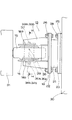
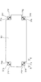
図1はこの発明の第1の実施の形態による係留装置の外観形状を示した平面図であり、図2は図1で示したII−IIラインの拡大端面図である。
これらの図を参照して、図1は背景技術として示した図11に対応した図であり、矩形平板状のベース板19に一対の架台18a,架台18bが固定されており、これらは一対の補強リブ33a,補強リブ33bと一対の補強リブ34a,補強リブ34bとによって補強されている。係留装置13の浮体構造物30側の面には矩形平板状の支持板25が固定されている。ベース板19と支持板25との間にはゴム等の緩衝材21が設置されている。緩衝材21のベース板19側には取付板22が接続され、接続ボルト及びナット26を介してベース板19に固定されている。一方、緩衝材21の支持板25側には取付板23が接続され、固定ボルト及びナット28を介して支持板25に固定されている。これにより係留杭31と浮体構造物30との間の距離の変動は緩衝材21によって吸収されるように構成されている。
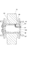
FIG. 1 is a plan view showing the external shape of a mooring device according to a first embodiment of the present invention, and FIG. 2 is an enlarged end view taken along line II-II shown in FIG.
Referring to these drawings, FIG. 1 is a diagram corresponding to FIG. 11 shown as the background art, and a pair of
一方、架台18a,架台18bを掛け渡すように中実円柱形状の軸16が水平方向に取り付けられている。軸16の第1端面42側には外方に広がるフランジ部41が形成されており、架台18aの外方側の面に当接状態となっている。
On the other hand, a solid
軸16の第2端面45側には円盤状の押え板46によって全面が覆われ、押え板46は架台18bの外方面に固定されている。押え板46の外方面には矩形平板状の固定板47が取り付けられ、押え板46及び固定板47を介して締付ボルト35a,締付ボルト35bが軸16に螺合するように締め付けられる。これによって、軸16は架台18a,架台18bにその両端が固定されることになる。
The entire surface of the
ローラー15は軸16に対して回動自在となるように軸16に取り付けられる。即ち、ローラー15は、その内周面が軸16の周壁部分に接した状態で回転することになる。これによって海面が上下することによって浮体構造物30が上下に移動した時、浮体構造物30に固定されている係留装置13はローラー15を係留杭31に接した状態で回転し、容易に海面の変動に追随することが可能となる。
The
軸16の第1端面42から内方に伸びる貫通孔43が形成されており、その端部は軸16の周壁部分であって、ローラー15の内周面に接する部分に形成された排出口38に連結されている。又、軸16のこの周壁部分には、排出口38に接続すると共に、軸16の軸方向に伸びる溝39が形成されている。そして、溝39の底部は、排出口38からその端部に向かって下方に傾斜するように形成されている。このようにこの実施の形態にあっては、軸16は固定されたものであり、排出口38及び溝39は軸16の最上部に常時位置することになる。
A through
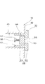
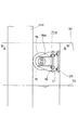
図3は図2で示した“X”部分の拡大図である。 FIG. 3 is an enlarged view of the “X” portion shown in FIG.
図を参照して、貫通孔43の軸16の露出部分には栓37が取り付けられている。栓37は、開口50を有すると共に、第1端面42に当接状態に取り付けられるフランジ部52と、フランジ部52に接続され、貫通孔43の内周面に当接状態となる円筒形状の胴部53とからなる栓本体49と、栓本体49の内部に設置され、開口50を塞ぐように付勢されている円柱形状の弁体55とから構成されている。尚、弁体55は胴部53に図示しない構造で固定されている支持体56に取り付けられている圧縮バネ57によって付勢されている。尚、外周壁58の直径に対して胴部53の内周面の直径は図のように若干大きくなるように設定されている。尚、この理由については後述する。
Referring to the figure, a
図4は、図1に示した係留装置に対して潤滑剤を注入するための注入管の外観形状を示した概略斜視図である。 FIG. 4 is a schematic perspective view showing an external shape of an injection tube for injecting a lubricant into the mooring device shown in FIG.
図を参照して、注入管60は円筒形状の胴部61の端部62側に4箇所の切欠き63が形成されている。この切欠き63の形成理由についても後述する。
Referring to the figure,
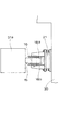
図5は図3で示した栓の使用状態を示した概略図である。 FIG. 5 is a schematic view showing a use state of the stopper shown in FIG.
潤滑剤を注入する場合には、図3の状態から、図5に示すように図4で示した形状の注入管60の先端を開口50内に挿入する。そして注入管60の端部62が弁体55の露出面に当接した状態で更に注入管60を押し込む。弁体55は胴部53によって付勢されているが、注入管60による内方への押圧力によって弁体55は内方に移動する。注入管60の先端は図4で示したように複数の切欠き63が形成されている。従って、図のような状態に注入管60の先端が位置すると、注入管を介して注入される潤滑剤は切欠き63を介して矢印のように流出する。
When injecting the lubricant, the tip of the
一方、弁体55の周壁と胴部53の内周壁との間には上述のようにスペース64が設けられているため、切欠き63から流出した潤滑剤はそのスペース64を通して貫通孔43内部へ進行する。貫通孔43内部に進行した潤滑剤は、図2に示すように排出口38から排出されると共に、その一部は溝39内部に進行することになる。この時、溝39の底面は排出口38から離れるにつれて下方に傾斜するように形成されているため、注入された潤滑剤は容易に溝39に進行する。
On the other hand, since the space 64 is provided between the peripheral wall of the
所定量の潤滑剤の注入が終了すると、図5の状態から注入管60を引き抜けば良い。すると、圧縮バネ57の付勢力によって弁体55はフランジ部52側に移動し、図3の状態に復帰する。これによって栓37は閉状態となるため、貫通孔43に注入された潤滑剤が栓37から外部に不用意に流出する虞はない。このように栓37を貫通孔43の入口に取り付けることによって開閉自在の弁としての機能が発揮するので、潤滑剤の注入及び停止作業が容易となる。
When the injection of the predetermined amount of lubricant is completed, the
潤滑剤の注入が終了すると、図2に示した貫通孔43、排出口38及び溝39内部に潤滑剤が充填された状態となる。尚、上述のように排出口38及び溝39は軸16における最上部に形成されているため、ローラー15が回転していないときに不用意に下方に潤滑剤が垂れて流出する虞がないので潤滑剤の保持効果が向上する。この状態でローラー15が軸16の周りを回動すると、注入された潤滑剤はこれらの接触面に広がり潤滑効果を安定して発揮する。
When the injection of the lubricant is completed, the lubricant is filled in the through
このようにこの実施の形態によれば、従来のようにローラー15を軸16から分解することなく、それらの接触面に容易に潤滑剤を注入することが可能となる。
Thus, according to this embodiment, it is possible to easily inject the lubricant into the contact surfaces without disassembling the
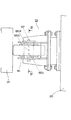
図6はこの発明の第2の実施の形態による係留装置の外観形状を示した平面図であり、図7は図6で示したVII−VIIラインの拡大端面図である。 FIG. 6 is a plan view showing the appearance of a mooring device according to a second embodiment of the present invention, and FIG. 7 is an enlarged end view of the VII-VII line shown in FIG.
これらの図を参照して、係留装置13の基本的な構成は先の第1の実施の形態によるものと同一であるため、ここでは、先の実施の形態とは相違する点について主に説明する。
With reference to these drawings, the basic configuration of the
軸16の第1端面42から内方に向かって貫通孔43が形成されている点は同じであるが、この実施の形態にあっては、複数の排出口65a〜排出口65cが形成されている点が異なっている。即ち、軸16の上方の周壁面において長手方向に3つの排出口65a〜排出口65cが形成されている。従って、栓37を介して注入された潤滑剤は排出口65a〜排出口65cの各々を介してローラー15と軸16との接触面に広がることになる。これによって潤滑剤の拡散が排出口が1箇所のものに比べて効率的に行われ、潤滑効果を更に高めることになる。尚、この実施の形態にあっても、排出口65a〜排出口65cの各々は軸16の周壁部における上方位置に形成されていることから、不用意な潤滑剤の垂れが防止され、潤滑剤の保持効果を向上させる。
Although the point that the through
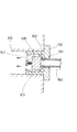
図8はこの発明の第3の実施の形態による係留装置の概略形状を示した断面図であり、先の第1の実施の形態の図2に対応するものである。 FIG. 8 is a sectional view showing a schematic shape of a mooring apparatus according to a third embodiment of the present invention, and corresponds to FIG. 2 of the first embodiment.
図を参照して、基本的な構造は第1の実施の形態による係留装置と同様であるため、共通部分については説明を繰り返さない。 Referring to the drawing, the basic structure is the same as that of the mooring apparatus according to the first embodiment, and therefore, the description of the common parts will not be repeated.
先の実施の形態にあっては、軸自体は中実の円柱形状を有しており、一般的には大型の係留装置に用いられる構造である。これに対して、この実施の形態にあっては、軸16は中空部分67を有する中空の円柱形状を有しており、一般的には中型又は小型の係留装置に用いられる構造である。
In the previous embodiment, the shaft itself has a solid cylindrical shape, and is generally a structure used for a large mooring device. On the other hand, in this embodiment, the
軸16の第1端面42には、中空部分67に達する貫通孔43が形成されている。一方、軸16の周壁部分に形成された溝39の一部に中空部分67に達する排出口38が形成されている。そして、貫通孔43と排出口38とを連結する接続管68が中空部分67に配置されている。又、貫通孔43には開閉自在の栓37が取り付けられている。
A through
使用に際しては、栓37を通して貫通孔43に潤滑剤を注入する。注入された潤滑剤は接続管68を通って排出口38から排出される。排出された潤滑剤は溝39に広がり、ローラー15と軸16の接触面における潤滑効果を発揮する。
In use, a lubricant is injected into the through
ところで、第2の実施の形態のように排出口が複数ある場合には、これらの排出口に接続できる形状の接続管を中空部分に準備すれば同様に適用でき、同様の効果を奏する。 By the way, when there are a plurality of outlets as in the second embodiment, a connecting pipe having a shape that can be connected to these outlets is prepared in the hollow portion, and the same effect can be obtained.
尚、上記の各実施の形態では、貫通孔は第1端面側からにのみ形成されているが、第2端面側からのみ形成されていても良く、あるいは双方の端面から形成されていても良い。この場合、第3の実施の形態にあっては、必要数の接続管を準備すれば良い。 In each of the above embodiments, the through hole is formed only from the first end face side, but may be formed only from the second end face side or may be formed from both end faces. . In this case, in the third embodiment, a necessary number of connection pipes may be prepared.
又、上記の各実施の形態では、常時固定で開閉自在の栓を貫通孔に取り付けているが、脱着式の栓を取り付けるように構成しても良い。 In each of the above-described embodiments, the always fixed and freely openable / closable stopper is attached to the through hole. However, a removable stopper may be attached.
更に、上記の各実施の形態では、栓の弁体の付勢手段として圧縮バネを用いているが、引っ張りバネ等の他の付勢手段を用いても良いことは言うまでもない。 Furthermore, in each of the above-described embodiments, the compression spring is used as the biasing means for the valve body of the stopper, but it goes without saying that other biasing means such as a tension spring may be used.
更に、上記の各実施の形態では、栓の弁体の周壁と栓本体との間にスペースが形成されているが、このスペースを無くしこの代わりに弁体の周壁に長手方向に延びる溝を複数形成するように構成しても良い。 Furthermore, in each of the above embodiments, a space is formed between the peripheral wall of the valve body of the plug and the plug body, but this space is eliminated, and instead, a plurality of grooves extending in the longitudinal direction are formed in the peripheral wall of the valve body. You may comprise so that it may form.
更に、上記の第1の実施の形態では、軸の外周壁に溝が形成されているが、この溝は必ずしもなくても良い。又、この溝は軸の上方部以外の位置に形成されていても良い。更に、この軸の底面は水平でも良く、あるいは逆の方向に傾斜していても良い。 Furthermore, in the first embodiment, a groove is formed on the outer peripheral wall of the shaft, but this groove is not necessarily required. The groove may be formed at a position other than the upper part of the shaft. Further, the bottom surface of the shaft may be horizontal or inclined in the opposite direction.
更に、上記の第2の実施の形態では、排出口は3箇所形成されているが、2箇所でも3箇所以上であっても良い。 Furthermore, in the second embodiment described above, three discharge ports are formed, but it may be two or more than three.
更に、上記の第2の実施の形態では、排出口は軸の長手方向の最上部に一列に整列しているが、最上部でなくても良く、あるいは整列状態でない位置に各々が形成されていても良い。 Furthermore, in the second embodiment described above, the discharge ports are aligned in a row at the uppermost portion in the longitudinal direction of the shaft. However, the discharge ports may not be the uppermost portion, or are formed at positions that are not aligned. May be.
13…係留装置
15…ローラー
16…軸
18…架台
30…浮体構造物
31…係留杭
37…栓
38…排出口
39…溝
42…第1端面
43…貫通孔
49…栓本体
55…弁体
67…中空部分
68…接続管
尚、各図中同一符号は同一又は相当部分を示す。
DESCRIPTION OF
Claims (7)
水平方向に伸びる軸と、
前記浮体構造物に取り付けられ、前記軸の両端部を固定する架台と、
前記軸に回動自在に取り付けられ、前記係留杭に接するローラーとを備え、
前記軸には、その少なくとも一方の端面に貫通孔が形成され、前記貫通孔は前記ローラーに接する前記軸の周壁部分に形成された排出口に接続され、前記軸は中空部を有する中空円柱形状を有し、前記貫通孔と前記排出口とは前記中空部を通る接続管を介して連結される、係留装置。 A mooring device attached to the side of the floating structure and used in contact with the mooring pile,
An axis extending horizontally,
A stand attached to the floating structure and fixing both ends of the shaft;
A roller that is pivotally attached to the shaft and that contacts the mooring pile;
The shaft has a through hole formed in at least one end surface thereof, the through hole is connected to a discharge port formed in a peripheral wall portion of the shaft in contact with the roller, and the shaft has a hollow cylindrical shape having a hollow portion. A mooring device, wherein the through hole and the discharge port are connected via a connecting pipe passing through the hollow portion.
水平方向に伸びる軸と、
前記浮体構造物に取り付けられ、前記軸の両端部を固定する架台と、
前記軸に回動自在に取り付けられ、前記係留杭に接するローラーとを備え、
前記軸には、その少なくとも一方の端面に貫通孔が形成され、前記貫通孔は前記ローラーに接する前記軸の周壁部分に形成された排出口に接続され、前記周壁部分には、前記排出口に接続すると共に前記軸の長手方向に伸びる溝が形成され、前記排出口は前記軸の上方部に形成され、前記溝の底部は前記排出口からその端部に向かって下方に傾斜するように形成される、係留装置。 A mooring device attached to the side of the floating structure and used in contact with the mooring pile,
An axis extending horizontally,
A stand attached to the floating structure and fixing both ends of the shaft;
A roller that is pivotally attached to the shaft and that contacts the mooring pile;
A through hole is formed in at least one end surface of the shaft, the through hole is connected to a discharge port formed in a peripheral wall portion of the shaft in contact with the roller, and the peripheral wall portion is connected to the discharge port. A groove that is connected and extends in the longitudinal direction of the shaft is formed, the discharge port is formed at an upper portion of the shaft, and a bottom portion of the groove is formed to be inclined downward from the discharge port toward an end thereof. Mooring equipment.
前記貫通孔の露出部分に取り付けられ、開口を有する栓本体と、
前記栓本体の内部に設置され、前記開口を塞ぐよう付勢されている弁体とを含む、請求項6記載の係留装置。 The stopper is
A plug body attached to the exposed portion of the through hole and having an opening;
The mooring device according to claim 6, further comprising: a valve body installed inside the stopper body and biased to close the opening.
Priority Applications (1)
| Application Number | Priority Date | Filing Date | Title |
|---|---|---|---|
| JP2006070128A JP4868898B2 (en) | 2006-03-15 | 2006-03-15 | Mooring equipment |
Applications Claiming Priority (1)
| Application Number | Priority Date | Filing Date | Title |
|---|---|---|---|
| JP2006070128A JP4868898B2 (en) | 2006-03-15 | 2006-03-15 | Mooring equipment |
Publications (2)
| Publication Number | Publication Date |
|---|---|
| JP2007245841A JP2007245841A (en) | 2007-09-27 |
| JP4868898B2 true JP4868898B2 (en) | 2012-02-01 |
Family
ID=38590583
Family Applications (1)
| Application Number | Title | Priority Date | Filing Date |
|---|---|---|---|
| JP2006070128A Expired - Lifetime JP4868898B2 (en) | 2006-03-15 | 2006-03-15 | Mooring equipment |
Country Status (1)
| Country | Link |
|---|---|
| JP (1) | JP4868898B2 (en) |
Families Citing this family (1)
| Publication number | Priority date | Publication date | Assignee | Title |
|---|---|---|---|---|
| JP7727304B2 (en) * | 2021-03-29 | 2025-08-21 | 三井住友建設鉄構エンジニアリング株式会社 | Mooring shock absorber |
Family Cites Families (9)
| Publication number | Priority date | Publication date | Assignee | Title |
|---|---|---|---|---|
| JPS57132704A (en) * | 1981-02-06 | 1982-08-17 | Matsushita Electric Works Ltd | Power distribution board |
| JPH02106998A (en) * | 1988-10-17 | 1990-04-19 | Fujitsu Ltd | Cable holder |
| JP3354578B2 (en) * | 1991-05-15 | 2002-12-09 | 株式会社ブリヂストン | Mooring equipment for floating structures |
| JPH0840354A (en) * | 1994-07-27 | 1996-02-13 | Shirashima Sekiyu Bichiku Kk | Levitation mooring equipment |
| JP3722885B2 (en) * | 1995-11-07 | 2005-11-30 | 株式会社ティクス | Shield engraving machine roller cutter |
| JPH11280773A (en) * | 1998-03-30 | 1999-10-15 | Kawasaki Steel Corp | Cylindrical rolling bearing and its lubrication device |
| JP2001012134A (en) * | 1999-06-29 | 2001-01-16 | Ykk Corp | Door car |
| JP4222069B2 (en) * | 2003-03-10 | 2009-02-12 | 株式会社ジェイテクト | Backup roll unit |
| JP4049036B2 (en) * | 2003-06-30 | 2008-02-20 | 三菱マテリアル株式会社 | Roller cutter |
-
2006
- 2006-03-15 JP JP2006070128A patent/JP4868898B2/en not_active Expired - Lifetime
Also Published As
| Publication number | Publication date |
|---|---|
| JP2007245841A (en) | 2007-09-27 |
Similar Documents
| Publication | Publication Date | Title |
|---|---|---|
| KR101312209B1 (en) | Up and down flow file guide | |
| US7918174B2 (en) | Anti-sloshing device in moon-pool | |
| KR100777236B1 (en) | Floating breakwater | |
| JP4868898B2 (en) | Mooring equipment | |
| KR100931545B1 (en) | Chemical Tube Fixture | |
| KR101444885B1 (en) | Rotary type movable weir | |
| KR20200001828A (en) | cable guide device for towing and towing method of floating marine structure using the same | |
| CN203336037U (en) | Platform pipeline supporting frame | |
| CN118958302A (en) | A subsea packer | |
| JP2011140797A (en) | Water intake device | |
| KR102375488B1 (en) | Self rotating surge and wave barrier | |
| KR101162441B1 (en) | Floating Structure | |
| JP2006342958A (en) | Fluid injection/delivery valve device | |
| CN217683503U (en) | Float valve | |
| KR102128795B1 (en) | Floater and assembly for mooring floater | |
| JP4846508B2 (en) | Control valve for fluid pipe | |
| KR200398056Y1 (en) | small animal moving for waterway pipe | |
| KR101352354B1 (en) | Fastening device for solarcell panel | |
| CN222509198U (en) | Flexible support structure and inland floating photovoltaic system | |
| JP3118366U (en) | Water bottle | |
| CN220555818U (en) | Combined soil and water conservation device | |
| TWM517258U (en) | Improved assembling structure of float ball holder | |
| KR102261752B1 (en) | Valve device having a pollution prevent funtion | |
| KR20160050230A (en) | Base Supporting Structure for Marine Structure and Marine Structure Having the Same | |
| KR101571422B1 (en) | Floating block, and offshore floating structure including the same |
Legal Events
| Date | Code | Title | Description |
|---|---|---|---|
| A621 | Written request for application examination |
Free format text: JAPANESE INTERMEDIATE CODE: A621 Effective date: 20090302 |
|
| A977 | Report on retrieval |
Free format text: JAPANESE INTERMEDIATE CODE: A971007 Effective date: 20110223 |
|
| A131 | Notification of reasons for refusal |
Free format text: JAPANESE INTERMEDIATE CODE: A131 Effective date: 20110329 |
|
| A521 | Request for written amendment filed |
Free format text: JAPANESE INTERMEDIATE CODE: A523 Effective date: 20110527 |
|
| TRDD | Decision of grant or rejection written | ||
| A01 | Written decision to grant a patent or to grant a registration (utility model) |
Free format text: JAPANESE INTERMEDIATE CODE: A01 Effective date: 20111025 |
|
| A01 | Written decision to grant a patent or to grant a registration (utility model) |
Free format text: JAPANESE INTERMEDIATE CODE: A01 |
|
| A61 | First payment of annual fees (during grant procedure) |
Free format text: JAPANESE INTERMEDIATE CODE: A61 Effective date: 20111115 |
|
| R150 | Certificate of patent or registration of utility model |
Ref document number: 4868898 Country of ref document: JP Free format text: JAPANESE INTERMEDIATE CODE: R150 Free format text: JAPANESE INTERMEDIATE CODE: R150 |
|
| FPAY | Renewal fee payment (event date is renewal date of database) |
Free format text: PAYMENT UNTIL: 20141125 Year of fee payment: 3 |
|
| R250 | Receipt of annual fees |
Free format text: JAPANESE INTERMEDIATE CODE: R250 |
|
| R250 | Receipt of annual fees |
Free format text: JAPANESE INTERMEDIATE CODE: R250 |
|
| R250 | Receipt of annual fees |
Free format text: JAPANESE INTERMEDIATE CODE: R250 |
|
| R250 | Receipt of annual fees |
Free format text: JAPANESE INTERMEDIATE CODE: R250 |