JP4868712B2 - Elevator damping device - Google Patents
Elevator damping device Download PDFInfo
- Publication number
- JP4868712B2 JP4868712B2 JP2004111943A JP2004111943A JP4868712B2 JP 4868712 B2 JP4868712 B2 JP 4868712B2 JP 2004111943 A JP2004111943 A JP 2004111943A JP 2004111943 A JP2004111943 A JP 2004111943A JP 4868712 B2 JP4868712 B2 JP 4868712B2
- Authority
- JP
- Japan
- Prior art keywords
- vibration
- elevator
- damping device
- car
- natural frequency
- Prior art date
- Legal status (The legal status is an assumption and is not a legal conclusion. Google has not performed a legal analysis and makes no representation as to the accuracy of the status listed.)
- Expired - Fee Related
Links
Images


Classifications
-
- B—PERFORMING OPERATIONS; TRANSPORTING
- B66—HOISTING; LIFTING; HAULING
- B66B—ELEVATORS; ESCALATORS OR MOVING WALKWAYS
- B66B11/00—Main component parts of lifts in, or associated with, buildings or other structures
- B66B11/02—Cages, i.e. cars
- B66B11/026—Attenuation system for shocks, vibrations, imbalance, e.g. passengers on the same side
- B66B11/028—Active systems
- B66B11/0286—Active systems acting between car and supporting frame
Landscapes
- Engineering & Computer Science (AREA)
- Civil Engineering (AREA)
- Mechanical Engineering (AREA)
- Structural Engineering (AREA)
- Cage And Drive Apparatuses For Elevators (AREA)
- Elevator Control (AREA)
Description
本発明は、かご室に変位自在に支持した可動錘を駆動して変位させることによりかご室の振動を減少させる制振装置に関し、より詳しくは、かご室の振動を効率良く減少することができるように制振装置を改良する技術に関する。 The present invention relates to a vibration damping device that reduces vibrations in a car room by driving and displacing a movable weight that is displaceably supported in the car room. More specifically, the vibration of the car room can be efficiently reduced. The present invention relates to a technique for improving a vibration damping device.
図7に示したように、エレベータの乗りかご1は、かご枠2上に振動絶縁体3を介して支持されたかご室4を有するとともに、図示されない巻上機から垂下するメインロープ5が振動絶縁体6を介してかご枠3に接続されて昇降路7の内部を昇降する。
また、かご枠2の上下の四隅に振動絶縁体8を介して支持されたガイドローラ9は、昇降路7の壁面7aに取り付けられて上下方向に延びる左右一対のガイドレール10L,10R上を転動して乗りかご1の昇降を案内する。
As shown in FIG. 7, the
このとき、ガイドレール10L,10Rにはわずかながら曲がりが生じているため、昇降路7内を昇降する乗りかご1にはガイドローラ9を介して横方向の加振力が作用する。 この加振力は、かご室4に伝わるまでの間に振動絶縁体8および振動絶縁体3によって有る程度減衰させることはできるものの、完全に遮断することはできない。
また、ガイドレール10L,10Rに生じている曲がりを取り除くためには、その据付および調整にかなりの作業工数を必要とする。
さらに、乗りかご1の昇降速度の増加に伴い、ガイドレール10L,10Rにはより高い据付精度が求められるが、その作業精度にも限界がある。
そこで、かご室4の横方向の振動を減衰させて乗り心地を向上させるための制振装置が提案されている(例えば、下記特許文献1を参照)。
At this time, the guide rails 10 </ b> L and 10 </ b> R are slightly bent, so that a lateral excitation force acts on the
Further, in order to remove the bending generated in the
Furthermore, with the increase in the raising / lowering speed of the
Therefore, a vibration damping device for improving the ride comfort by attenuating the lateral vibration of the
図7に示した制振装置12は、かご室4の底部に固定されており、駆動モータ13によって正逆両方向に回転駆動されるボールねじ14と、このボールねじ14に螺合してその軸線方向に往復変位させられる可動錘15と、かご室4に固定された加速度計16から得られる信号に基づいて駆動モータ13の作動を制御する制御手段17とを備えている。
これにより、可動錘15を強制変位させて得られる慣性力によってかご室4に生じた振動を打ち消し、その乗り心地を向上させることができる。
The
As a result, it is possible to cancel the vibration generated in the
ところで、上述した従来の制振装置12においては、加速度計16から出力される信号の中に風による建屋の揺れに伴う振動成分も含まれているため、制御手段17は建屋の揺れに伴う振動成分をも打ち消そうとして可動錘15を駆動してしまう。
しかしながら、建屋の揺れは、高階床で柔構造の場合には非常に低い周波数(0.5Hz以下)であり、その変位も数百mmのオーダーになる。
これにより、このような振動成分を打ち消すためには、可動錘15の質量を非常に大きくしたり可動錘15の変位ストロークを非常に大きく設定したりする必要があり、制振装置12の大型化を招くことになる。
また、耐震上の観点から、ガイドレール10L,10Rと乗りかご2との間の相対変位は数mmであって、建屋の揺れに対しては制振装置による対応の範囲外であり、かつ建屋自体が揺れているのだから対応も不要である。
By the way, in the conventional
However, the shaking of the building is a very low frequency (0.5 Hz or less) in the case of a flexible structure with a high floor, and its displacement is on the order of several hundred mm.
Accordingly, in order to cancel such a vibration component, it is necessary to increase the mass of the
Further, from the viewpoint of earthquake resistance, the relative displacement between the
また、かご室4の振動を減少させて乗り心地を向上させる際に問題となる振動は、ガイドローラ9に付設されている振動絶縁体8や、かご枠2とかご室4との間に介装されている振動絶縁体3における低次の固有周波数の振動である。
したがって、制振装置12によって制振しようとする振動の周波数を不必要に拡げることは、制振装置12の大型化を招くばかりでなく、制振が必要な周波数帯における制振効率の低下をも招いてしまう。
In addition, vibration which becomes a problem when improving the riding comfort by reducing the vibration of the
Therefore, unnecessarily widening the frequency of the vibration to be controlled by the
さらに、制振装置12において発生する駆動モータ13の高調波振動等がかご室4に伝播すると、かご室4内における乗り心地の悪化を招いてしまう。
加えて、ボールねじ14等の可動部分に外部から異物が侵入すると装置が劣化し、滑らかな作動が妨げられて制振作用の低下を招くおそれもある。
Furthermore, when harmonic vibrations of the
In addition, when foreign matter enters the movable part such as the
そこで本発明の目的は、上述した従来技術が有する問題点を解消し、かご室に生じている振動を効率良く制振してかご室内における乗り心地を向上させることができるエレベータの制振装置を提供することにある。 SUMMARY OF THE INVENTION An object of the present invention is to provide an elevator vibration damping device that solves the above-described problems of the prior art and that can efficiently damp vibrations generated in a car room to improve the riding comfort in the car room. It is to provide.
上記の課題を解決する請求項1に記載した手段は、
エレベータのかご室に生じる振動を制振するために前記かご室に設けられる制振装置であって、
前記エレベータが、
前記かご室を支持しているかご枠と、
昇降路のガイドレールと協動して前記かご枠の昇降を案内する、前記かご枠に設けられた案内手段と、
前記案内手段と前記かご枠との間に介装された第1の振動絶縁手段と、
前記かご枠と前記かご室との間に介装された第2の振動絶縁手段と、を備えており、
かつ前記制振装置が、
前記かご室に変位自在に支持された可動錘と、
前記可動錘を駆動して変位させる駆動手段と、
前記かご室に生じている振動を計測する振動計測手段と、
前記振動計測手段から得られる信号のうち、前記第1の振動絶縁手段の低次固有周波数を含む周波数帯の信号を通過させる第1のフィルタ手段と、
前記振動計測手段から得られる信号のうち、前記第2の振動絶縁手段の低次固有周波数を含む周波数帯の信号を通過させる第2のフィルタ手段と、
前記振動計測手段から得られる信号より、前記エレベータを設置した建屋の低次固有周波数成分を取り除く第3のフィルタ手段と、
前記振動計測手段から得られる信号のうち、前記第1および第2のフィルタ手段を通過しかつ前記第3のフィルタ手段を通過した信号に基づいて前記駆動手段の作動を制御する制御手段と、を有していることを特徴とする。
なお、第1〜第3のフィルタ手段として、ローパスフィルタ、ハイパスフィルタ、ノッチフィルタの組み合わせ等を用いることができる。
The means described in
A vibration damping device provided in the car room for damping vibration generated in the elevator car room,
The elevator is
A car frame supporting the car room;
Guidance means provided on the car frame for guiding the raising and lowering of the car frame in cooperation with a guide rail of the hoistway;
First vibration isolation means interposed between the guide means and the car frame;
Second vibration isolation means interposed between the car frame and the car room,
And the damping device is
A movable weight supported movably in the cage;
Driving means for driving and displacing the movable weight;
Vibration measuring means for measuring vibration generated in the cab;
Of the signals obtained from the vibration measurement means, a first filter means for passing a signal in a frequency band including a low-order natural frequency of the first vibration isolation means;
Of the signals obtained from the vibration measuring means, second filter means for passing a signal in a frequency band including a low-order natural frequency of the second vibration isolating means;
Third filter means for removing low-order natural frequency components of the building where the elevator is installed from the signal obtained from the vibration measuring means;
Control means for controlling the operation of the driving means based on the signal that has passed through the first and second filter means and passed through the third filter means among the signals obtained from the vibration measuring means ; It is characterized by having.
As the first to third filter means, a combination of a low-pass filter, a high-pass filter, a notch filter, or the like can be used.
すなわち、請求項1に記載したエレベータの制振装置においては、加速度計等の振動計測手段から得られる信号のうち、第1の振動絶縁手段の低次固有周波数を含む周波数帯の信号のみを通過させる、言い換えると第1の振動絶縁手段の低次固有周波数を含む周波数帯以外の周波数帯のゲインを低下させるために第1のフィルタ手段を用いる。
これにより、第1の振動絶縁手段の低次固有周波数に起因してガイドレールとかご枠との間に生じる振動を制振するために、可動錘および駆動手段を集中的に用いることができる。
That is, in the elevator vibration damping device according to
As a result, the movable weight and the driving means can be intensively used to control the vibration generated between the guide rail and the car frame due to the low-order natural frequency of the first vibration isolation means.
また、請求項1に記載したエレベータの制振装置においては、加速度計等の振動計測手段から得られる信号のうち、第2の振動絶縁手段の低次固有周波数を含む周波数帯の信号のみを通過させる、言い換えると第2の振動絶縁手段の低次固有周波数を含む周波数帯以外の周波数帯のゲインを低下させるために第2のフィルタ手段を用いる。
これにより、第2の振動絶縁手段の低次固有周波数に起因してかご枠とかご室との間に生じる振動を制振するために、可動錘および駆動手段を集中的に用いることができる。
したがって、可動錘および駆動手段による制振能力を限定して小型軽量化を図ることができるから、乗りかごの質量を減少させることもできるし、駆動手段を作動させるために必要な電力を低減することもできる。
In the elevator vibration damping device according to
As a result, the movable weight and the driving means can be intensively used to control the vibration generated between the car frame and the car room due to the low-order natural frequency of the second vibration isolating means.
Therefore, since the vibration control capability by the movable weight and the driving means can be limited and the size and weight can be reduced, the mass of the car can be reduced, and the electric power necessary for operating the driving means can be reduced. You can also.
さらに、請求項1に記載したエレベータの制振装置においては、加速度計等の振動計測手段から得られる信号から、エレベータを設置した建屋の低次固有周波数成分を取り除くために、言い換えると建屋の低次固有周波数成分のゲインを低めるために第3のフィルタ手段を用いる。
これにより、かご室の振動に含まれている建屋の低次固有周波数成分を制振するために駆動手段を作動させる必要が無く、また可動錘の変位ストロークを小さくするとともに可動錘を軽量化することができるから、制振装置全体を小型化することが可能となり、かつ駆動手段を作動させるために必要な電力を低減することもできる。
Furthermore, in the elevator vibration damping device according to
As a result, it is not necessary to operate the driving means to dampen the low-order natural frequency component of the building included in the vibration of the cab, and the displacement stroke of the movable weight is reduced and the movable weight is reduced in weight. Therefore, it is possible to reduce the size of the entire vibration damping device, and it is possible to reduce the electric power necessary for operating the driving means.
また、上記の課題を解決する請求項2に記載した手段は、請求項1に記載したエレベータの制振装置において、少なくとも前記可動錘および前記駆動手段が、第3の振動絶縁手段を介して前記かご室に取り付けられていることを特徴とする。 According to a second aspect of the present invention, there is provided the vibration damping device for an elevator according to the first aspect, wherein at least the movable weight and the driving means are connected to each other via a third vibration isolation means. It is attached to the cab.
すなわち、請求項2に記載したエレベータの制振装置によれば、駆動手段等が発生する高周波数の振動のかご室への伝播を防止できるから、かご室内の騒音を低減して乗り心地を向上させることができる。
In other words, according to the elevator vibration control device described in
また、上記の課題を解決する請求項3に記載した手段は、請求項1または2に記載したエレベータの制振装置が、少なくとも前記可動錘および前記駆動手段を密閉する、前記かご室に対して着脱自在に取り付けられた密閉手段をさらに備えることを特徴としている。 According to a third aspect of the present invention for solving the above problems, the elevator vibration control device according to the first or second aspect of the present invention is provided for the cab that seals at least the movable weight and the driving means. It is further characterized by further comprising a sealing means detachably attached.
すなわち、請求項3に記載したエレベータの制振装置によれば、駆動手段等に含まれる精密可動部品に塵芥等が付着することを防止できるばかりでなく、駆動手段等が発生する高周波数の振動が空気を介して伝播することを防止することもできる。
また、点検時には密閉手段を取り外せばよく、重量の有る装置全体を取り外す必要が無いから、メンテナンスを簡単に行うこともできる。
That is, according to the vibration damping device for an elevator according to
Further, it is only necessary to remove the sealing means at the time of inspection, and since it is not necessary to remove the heavy apparatus as a whole, maintenance can be easily performed.
また、上記の課題を解決する請求項4に記載した手段は、請求項1乃至3のいずれかに記載したエレベータの制振装置が、前記振動計測手段から得られる信号を周波数分析して前記エレベータを設置した建屋の低次固有周波数の値を演算する周波数分析演算部と、演算によって得られた前記建屋の低次固有周波数の値を表示する表示部と、をさらに有することを特徴としている。 According to a fourth aspect of the present invention for solving the above-mentioned problem, the elevator vibration control device according to any one of the first to third aspects performs frequency analysis on a signal obtained from the vibration measuring means to perform the elevator. The frequency analysis calculation unit that calculates the value of the low-order natural frequency of the building where the building is installed, and the display unit that displays the value of the low-order natural frequency of the building obtained by the calculation are further provided.
すなわち、請求項4に記載したエレベータの制振装置によれば、振動計測手段から得られた信号をフィルタ手段に通すことなく制御手段に取り込んで、その周波数分析演算部において処理し、表示器に表示することにより、建屋の固有振動数を知ることができる。
したがって、建屋の固有振動数を知るために別の測定器を用意する必要が無い。
また、建屋の固有振動数を直接知ることができるから、制御手段の作動が最適となるように制御手段を調整することができ、良好な制振作用を得ることができる。
That is, according to the vibration damping device for an elevator according to
Therefore, it is not necessary to prepare another measuring device in order to know the natural frequency of the building.
In addition, since the natural frequency of the building can be directly known, the control means can be adjusted so that the operation of the control means is optimal, and a good vibration damping action can be obtained.
以上の説明から明らかなように、本発明によれば、かご室に生じている振動を効率良く制振してかご室内における乗り心地を向上させることができるエレベータの制振装置を提供することができる。 As is apparent from the above description, according to the present invention, it is possible to provide a vibration damping device for an elevator that can efficiently damp vibrations generated in a car room and improve the riding comfort in the car room. it can.
以下、図1乃至図6を参照し、本発明に係るエレベータの制振装置の一実施形態について詳細に説明する。なお、以下の説明においては、同一の部分には同一の符号を用いて重複した説明を省略することがある。 Hereinafter, an embodiment of a vibration damping device for an elevator according to the present invention will be described in detail with reference to FIGS. 1 to 6. In the following description, the same parts may be denoted by the same reference numerals and redundant description may be omitted.
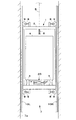
まず最初に図1を参照し、本第1実施形態の制振装置を適用するエレベータの構造について概説すると、乗りかご1は、かご枠2上に振動絶縁体(第2の振動絶縁体)3を介して支持されたかご室4を有するとともに、図示されない巻上機から垂下するメインロープ5が振動絶縁体6を介してかご枠3に接続されて昇降路7の内部を昇降する。
また、かご枠2の上下の四隅に振動絶縁体(第1の振動絶縁体)8を介して支持されたガイドローラ9は、昇降路7の壁面7aに取り付けられて上下方向に延びる左右一対のガイドレール10L,10R上を転動し、乗りかご2の昇降を案内する。
そして、かご室4の横方向の振動を減衰させて乗り心地を向上させるために、かご室4の底部には制振装置20が装着されている。
First, referring to FIG. 1, the structure of an elevator to which the vibration damping device of the first embodiment is applied will be outlined. A
A
A
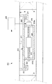
制振装置20は、図2に示したように、かご室4の底面に固着された固定部材21と、この固定部材21上に振動絶縁体(第3の振動絶縁体)22を介して支持されたフレーム23とを有している。
また、フレーム23の左右の縦壁23a,23b間に回転自在に支持されて図示左右方向に延びるねじロッド24は、図示右側の縦壁23bに設けられた駆動モータ25によって正逆両方向に回転させることができる。
さらに、ねじロッド24には可動錘26が螺合しており、ねじロッド24の回転によって図示左右方向に変位させることができる。
加えて、かご室4には加速度計(振動計測手段)27が設けられており、かご室4に生じている振動を計測して制御手段28に出力するようになっている。
As shown in FIG. 2, the
A
Further, a
In addition, the
制御手段28においては、図3に模式的に示したように、加速度計27から入力する加速度信号31がローパスフィルタ32,ハイパスフィルタ33,ノッチフィルタ34,積分器35,増幅器36を介して処理され、加算器37に入力する。
一方、図示されない錘位置センサから得られる錘位置信号38は、錘位置信号制御演算部39において処理された後に加算器37に入力し、結果として得られる可動錘推力指令信号が駆動モータ25に出力される。
なお、図3には各フィルタ(フィルタ手段)を直列に接続しているが、必要に応じて使用するフィルタの種類を変更したり並列に接続したりすることもできる。
In the control means 28, as schematically shown in FIG. 3, the
On the other hand, the
In addition, although each filter (filter means) is connected in series in FIG. 3, the kind of filter to be used can be changed as necessary, or can be connected in parallel.
また、図4に示したゲイン線図は、41がローパスフィルター,42がハイパスフィルター,43がノッチフィルターの遮断特性を示している。
このゲイン線図から明らかなように、加速度計27から流力する信号のうち、エレベータを設置した建屋の低次固有周波数成分に対するゲインが低められている。
また、第1および第2の振動絶縁手段8,3の低次固有周波数を含む周波数帯以外の周波数帯のゲインが低められている。
Further, the gain diagram shown in FIG. 4 shows the cutoff characteristics of 41 as a low-pass filter, 42 as a high-pass filter, and 43 as a notch filter.
As is apparent from this gain diagram, among the signals flowing from the
Further, the gain of the frequency band other than the frequency band including the low-order natural frequency of the first and second
すなわち、本実施形態の制振装置20においては、ノッチフィルタ34を通過した加速度信号31には、エレベータを設置した建屋の低次固有周波数成分が含まれていない。
これにより、かご室4の振動に含まれている建屋の低次固有周波数成分を制振するように制御手段28が駆動モータ25を作動させることがないから、可動錘26の変位ストロークを小さく設定して制振装置20を小型化することが可能となるし、駆動モータ25を作動させるために必要な電力を低減することもできる。
That is, in the
Thereby, since the control means 28 does not operate the
また、本実施形態の制振装置20においては、ローパスフィルタ32,ハイパスフィルタ33を通過した加速度信号31には、振動絶縁体(第1の振動絶縁体)8に起因してガイドレール10L,10Rとかご枠2ちの間に生じる振動の周波数成分、および振動絶縁体(第2の振動絶縁体)3の固有周波数に起因してかご枠2との間に生じる振動の周波数成分が主に含まれている。
これにより、かご室4に生じている振動を制振するために可動錘26および駆動モータ25を集中的に用いることができる。
したがって、可動錘26および駆動モータ25を小型軽量化することができるから、かご室4の質量をも減少させることができるし、駆動モータ25を作動させるために必要な電力を低減することもできる。
Further, in the
As a result, the
Therefore, since the
また、図5には、制振装置20を内蔵して密閉するための筐体(密閉手段)50が示されている。
この筐体50は、かご室4の底面に固定されて制振装置20を内蔵する箱状の本体部分51と、この本体部分の下方の開口を着脱自在に開閉する蓋体52とを有しており、ボルト53によって蓋体52を本体部分に固定する構造となっている。
Further, FIG. 5 shows a housing (sealing means) 50 for enclosing and sealing the
The
これにより、ねじロッド24や駆動モータ25等に含まれる精密可動部品に塵芥等が付着することを防止できるばかりでなく、駆動モータ25等が発生する高周波数の振動が空気を介してかご室4の内部に伝播することを防止することもできる。
また、点検時には蓋体52を取り外せばよく、重量の有る制振装置20の全体を取り外す必要が無いから、メンテナンスを簡単に行うことができる。
This not only prevents dust and the like from adhering to precision movable parts included in the
In addition, the
さらに、図6は制振装置20に含まれている機能を示しており、かご室4に取り付けられている加速度計27から得られた加速度信号61は、各フィルタを通ることなく制御手段28の周波数分析部62に直接入力する。
すると、周波数分析演算部62は、加速度信号61を処理することによりエレベータを設けた建屋の固有振動数を算出し、表示部63に表示させる。
Further, FIG. 6 shows the functions included in the
Then, the frequency
これにより、建屋の固有振動数を知るために別の測定器を用意する必要が無いばかりでなく、建屋の固有振動数に合わせて制御手段28の作動が最適となるように制御手段28の設定を現場におて調整できるから、良好な制振作用を達成することができる。 Thereby, it is not necessary to prepare another measuring device to know the natural frequency of the building, and the control means 28 is set so that the operation of the control means 28 is optimized in accordance with the natural frequency of the building. Can be adjusted at the site, so that a good vibration control action can be achieved.
1 乗りかご
2 かご枠
3 振動絶縁体(第2の振動絶縁体)
4 かご室
5 メインロープ
6 振動絶縁体
7 昇降路
7a 壁面
8 振動絶縁体(第1の振動絶縁体)
9 ガイドローラ
10L,10R ガイドレール
12 従来の制振装置
13 駆動モータ
14 ボールねじ
15 可動錘
16 加速度計
17 制御手段
20 本発明の制振装置
21 固定部材
22 振動絶縁体(第3の振動絶縁体)
23 支持フレーム
24 ねじロッド
25 駆動モータ
26 可動錘
27 加速度計
28 制御手段
31 加速度信号
32 ローパスフィルタ
33 ハイパスフィルタ
34 ノッチフィルタ
35 積分器
36 増幅器
37 加算器
38 錘位置信号
39 錘位置信号制御演算部
41 ローパスフィルタの遮断特性
42 ハイパスフィルタの遮断特性
43 ノッチフィルタの遮断特性
50 筐体
51 本体部分
52 蓋体
53 ボルト
61 加速度信号
62 周波数分析演算部
63 表示部
1
4
9
DESCRIPTION OF
23
Claims (4)
前記エレベータが、
前記かご室を支持しているかご枠と、
昇降路のガイドレールと協動して前記かご枠の昇降を案内する、前記かご枠に設けられた案内手段と、
前記案内手段と前記かご枠との間に介装された第1の振動絶縁手段と、
前記かご枠と前記かご室との間に介装された第2の振動絶縁手段と、を備えており、
かつ前記制振装置が、
前記かご室に変位自在に支持された可動錘と、
前記可動錘を駆動して変位させる駆動手段と、
前記かご室に生じている振動を計測する振動計測手段と、
前記振動計測手段から得られる信号のうち、前記第1の振動絶縁手段の低次固有周波数を含む周波数帯の信号を通過させる第1のフィルタ手段と、
前記振動計測手段から得られる信号のうち、前記第2の振動絶縁手段の低次固有周波数を含む周波数帯の信号を通過させる第2のフィルタ手段と、
前記振動計測手段から得られる信号より、前記エレベータを設置した建屋の低次固有周波数成分を取り除く第3のフィルタ手段と、
前記振動計測手段から得られる信号のうち、前記第1および第2のフィルタ手段を通過しかつ前記第3のフィルタ手段を通過した信号に基づいて前記駆動手段の作動を制御する制御手段と、
を有していることを特徴とするエレベータの制振装置。 A vibration damping device provided in the car room for damping vibration generated in the elevator car room,
The elevator is
A car frame supporting the car room;
Guidance means provided on the car frame for guiding the raising and lowering of the car frame in cooperation with a guide rail of the hoistway;
First vibration isolation means interposed between the guide means and the car frame;
Second vibration isolation means interposed between the car frame and the car room,
And the damping device is
A movable weight supported movably in the cage;
Driving means for driving and displacing the movable weight;
Vibration measuring means for measuring vibration generated in the cab;
Of the signals obtained from the vibration measurement means, a first filter means for passing a signal in a frequency band including a low-order natural frequency of the first vibration isolation means;
Of the signals obtained from the vibration measuring means, second filter means for passing a signal in a frequency band including a low-order natural frequency of the second vibration isolating means;
Third filter means for removing low-order natural frequency components of the building where the elevator is installed from the signal obtained from the vibration measuring means;
Control means for controlling the operation of the drive means based on the signal that has passed through the first and second filter means and passed through the third filter means among signals obtained from the vibration measuring means ;
An elevator vibration control device characterized by comprising:
演算によって得られた前記建屋の低次固有周波数の値を表示する表示部と、
をさらに有することを特徴とする請求項1乃至3のいずれかに記載したエレベータの制振装置。 A frequency analysis calculation unit that calculates a value of a low-order natural frequency of a building in which the elevator is installed by performing frequency analysis on a signal obtained from the vibration measurement unit;
A display unit for displaying a value of a low-order natural frequency of the building obtained by calculation;
The elevator vibration damping device according to any one of claims 1 to 3, further comprising:
Priority Applications (5)
| Application Number | Priority Date | Filing Date | Title |
|---|---|---|---|
| JP2004111943A JP4868712B2 (en) | 2004-04-06 | 2004-04-06 | Elevator damping device |
| CNA2005800102324A CN1938214A (en) | 2004-04-06 | 2005-04-05 | Damping device of elevator |
| EP05728716A EP1739047A4 (en) | 2004-04-06 | 2005-04-05 | Damping device of elevator |
| PCT/JP2005/006666 WO2005097655A1 (en) | 2004-04-06 | 2005-04-05 | Damping device of elevator |
| TW94110903A TWI290532B (en) | 2004-04-06 | 2005-04-06 | Damping device for elevator |
Applications Claiming Priority (1)
| Application Number | Priority Date | Filing Date | Title |
|---|---|---|---|
| JP2004111943A JP4868712B2 (en) | 2004-04-06 | 2004-04-06 | Elevator damping device |
Publications (2)
| Publication Number | Publication Date |
|---|---|
| JP2005298071A JP2005298071A (en) | 2005-10-27 |
| JP4868712B2 true JP4868712B2 (en) | 2012-02-01 |
Family
ID=35124959
Family Applications (1)
| Application Number | Title | Priority Date | Filing Date |
|---|---|---|---|
| JP2004111943A Expired - Fee Related JP4868712B2 (en) | 2004-04-06 | 2004-04-06 | Elevator damping device |
Country Status (5)
| Country | Link |
|---|---|
| EP (1) | EP1739047A4 (en) |
| JP (1) | JP4868712B2 (en) |
| CN (1) | CN1938214A (en) |
| TW (1) | TWI290532B (en) |
| WO (1) | WO2005097655A1 (en) |
Families Citing this family (10)
| Publication number | Priority date | Publication date | Assignee | Title |
|---|---|---|---|---|
| JP5009304B2 (en) * | 2006-12-13 | 2012-08-22 | 三菱電機株式会社 | Elevator equipment |
| JP2010180033A (en) * | 2009-02-06 | 2010-08-19 | Toshiba Elevator Co Ltd | Elevator vibration control device |
| RU2014103534A (en) * | 2011-08-08 | 2015-09-20 | Отис Элевэйтор Компани | ELECTRONIC SCHEMES OF THE DRIVE AND LIFT IN THE SUPPORT PLATE |
| JP2013095570A (en) * | 2011-11-02 | 2013-05-20 | Hitachi Ltd | Elevator including damping device |
| WO2013088507A1 (en) * | 2011-12-13 | 2013-06-20 | 三菱電機株式会社 | Active movement attenuator and elevator oscillation control method |
| CN105347143B (en) * | 2015-11-27 | 2018-07-03 | 东南电梯股份有限公司 | A kind of no guide rail hydraulic elevating platform and elevating method |
| JP6449179B2 (en) * | 2016-01-22 | 2019-01-09 | 株式会社日立ビルシステム | Elevator |
| JP6203334B1 (en) * | 2016-06-06 | 2017-09-27 | 東芝エレベータ株式会社 | Elevator active vibration control device |
| CN107673175A (en) * | 2017-10-18 | 2018-02-09 | 陕西省特种设备质量安全监督检测中心 | A kind of express elevator for being capable of even running |
| JP7392772B1 (en) | 2022-06-30 | 2023-12-06 | フジテック株式会社 | signal processing device |
Family Cites Families (7)
| Publication number | Priority date | Publication date | Assignee | Title |
|---|---|---|---|---|
| DE3041491A1 (en) * | 1980-11-04 | 1982-05-13 | Elb-Schliff Edmund Lang, 6113 Babenhausen | CONTROL FOR THE HYDRAULIC DRIVE OF THE WORKING TABLE OF A FLAT GRINDING MACHINE |
| JP3213220B2 (en) * | 1995-10-23 | 2001-10-02 | 株式会社東芝 | Elevator cab damper |
| JPH09151064A (en) * | 1995-12-04 | 1997-06-10 | Otis Elevator Co | Rope type elevator |
| JPH11116166A (en) * | 1997-10-15 | 1999-04-27 | Toshiba Corp | Vibration control device of elevator |
| SG89424A1 (en) * | 2000-10-23 | 2002-06-18 | Inventio Ag | Method and system for compensating vibrations in elevator cars |
| JP2002356287A (en) * | 2001-05-31 | 2002-12-10 | Mitsubishi Electric Corp | Vibration-proofing device of elevator |
| JP2003112862A (en) * | 2001-10-04 | 2003-04-18 | Toshiba Elevator Co Ltd | Elevator vibration monitoring device |
-
2004
- 2004-04-06 JP JP2004111943A patent/JP4868712B2/en not_active Expired - Fee Related
-
2005
- 2005-04-05 CN CNA2005800102324A patent/CN1938214A/en active Pending
- 2005-04-05 EP EP05728716A patent/EP1739047A4/en not_active Withdrawn
- 2005-04-05 WO PCT/JP2005/006666 patent/WO2005097655A1/en not_active Application Discontinuation
- 2005-04-06 TW TW94110903A patent/TWI290532B/en not_active IP Right Cessation
Also Published As
| Publication number | Publication date |
|---|---|
| EP1739047A4 (en) | 2008-07-23 |
| EP1739047A1 (en) | 2007-01-03 |
| TWI290532B (en) | 2007-12-01 |
| CN1938214A (en) | 2007-03-28 |
| JP2005298071A (en) | 2005-10-27 |
| TW200604086A (en) | 2006-02-01 |
| WO2005097655A1 (en) | 2005-10-20 |
Similar Documents
| Publication | Publication Date | Title |
|---|---|---|
| EP1739047A1 (en) | Damping device of elevator | |
| KR101088275B1 (en) | Elevator device | |
| US5027925A (en) | Procedure and apparatus for damping the vibrations of an elevator car | |
| JP2000072359A (en) | Elevator device | |
| US20090308696A1 (en) | Vibration damping device of elevator | |
| JP4810539B2 (en) | Elevator vibration reduction device | |
| JP2865949B2 (en) | Elevator damping device | |
| JP4762483B2 (en) | Elevator vibration reduction device | |
| JP2008168980A (en) | Vertical vibration suppression device for elevator car | |
| JP5388054B2 (en) | Elevator with elevator vibration control device | |
| JPH11116166A (en) | Vibration control device of elevator | |
| JP2011105435A (en) | Elevator vibration damping system | |
| JP5528997B2 (en) | Elevator cab vibration reduction device | |
| JP2009256056A (en) | Elevator vibration control device | |
| JP2002193566A (en) | Elevator device | |
| JP4122761B2 (en) | Elevator equipment | |
| JP6819752B1 (en) | Main rope runout suppression device | |
| JP2008214076A (en) | Elevator car vibration-damping device | |
| JP6243245B2 (en) | Elevator equipment | |
| JP2007008668A (en) | Vertical vibration restricting device for elevator car | |
| JP2011111303A (en) | Vertical vibration restricting device for elevator car | |
| JPH0449191A (en) | Vibration-preventing device for elevator | |
| JP2005162391A (en) | Elevator device | |
| KR100275580B1 (en) | Vibration reduction device of elevator | |
| JP2021107259A (en) | Oscillating suppression device of main rope |
Legal Events
| Date | Code | Title | Description |
|---|---|---|---|
| A621 | Written request for application examination |
Free format text: JAPANESE INTERMEDIATE CODE: A621 Effective date: 20070320 |
|
| A131 | Notification of reasons for refusal |
Free format text: JAPANESE INTERMEDIATE CODE: A131 Effective date: 20100622 |
|
| A521 | Request for written amendment filed |
Free format text: JAPANESE INTERMEDIATE CODE: A523 Effective date: 20100823 |
|
| A131 | Notification of reasons for refusal |
Free format text: JAPANESE INTERMEDIATE CODE: A131 Effective date: 20110218 |
|
| A521 | Request for written amendment filed |
Free format text: JAPANESE INTERMEDIATE CODE: A523 Effective date: 20110419 |
|
| TRDD | Decision of grant or rejection written | ||
| A01 | Written decision to grant a patent or to grant a registration (utility model) |
Free format text: JAPANESE INTERMEDIATE CODE: A01 Effective date: 20111021 |
|
| A01 | Written decision to grant a patent or to grant a registration (utility model) |
Free format text: JAPANESE INTERMEDIATE CODE: A01 |
|
| A61 | First payment of annual fees (during grant procedure) |
Free format text: JAPANESE INTERMEDIATE CODE: A61 Effective date: 20111115 |
|
| R150 | Certificate of patent or registration of utility model |
Ref document number: 4868712 Country of ref document: JP Free format text: JAPANESE INTERMEDIATE CODE: R150 Free format text: JAPANESE INTERMEDIATE CODE: R150 |
|
| FPAY | Renewal fee payment (event date is renewal date of database) |
Free format text: PAYMENT UNTIL: 20141125 Year of fee payment: 3 |
|
| S531 | Written request for registration of change of domicile |
Free format text: JAPANESE INTERMEDIATE CODE: R313531 |
|
| R350 | Written notification of registration of transfer |
Free format text: JAPANESE INTERMEDIATE CODE: R350 |
|
| LAPS | Cancellation because of no payment of annual fees |