JP4865371B2 - Spindle cooling device for machine tools - Google Patents
Spindle cooling device for machine tools Download PDFInfo
- Publication number
- JP4865371B2 JP4865371B2 JP2006071775A JP2006071775A JP4865371B2 JP 4865371 B2 JP4865371 B2 JP 4865371B2 JP 2006071775 A JP2006071775 A JP 2006071775A JP 2006071775 A JP2006071775 A JP 2006071775A JP 4865371 B2 JP4865371 B2 JP 4865371B2
- Authority
- JP
- Japan
- Prior art keywords
- cooling
- spindle
- cooling medium
- air
- paths
- Prior art date
- Legal status (The legal status is an assumption and is not a legal conclusion. Google has not performed a legal analysis and makes no representation as to the accuracy of the status listed.)
- Active
Links
Images


Description
本発明は、工作機械の主軸内部に設けられたスピンドルを冷却する工作機械のスピンドル冷却装置に関する。 The present invention relates to a spindle cooling device for a machine tool that cools a spindle provided inside a spindle of the machine tool.
従来、工作機械の一例であるマシニングセンタでは、主軸に取り付けられた工具によって被加工物(ワーク)に機械加工(例えば、「中ぐり」、「フライス削り」、「穴空け」、「切削」等)を施している。そして、主軸に取り付けられた工具を主軸モータの動力によって回転させるために、主軸内部に設けられたスピンドルを主軸モータに連結して回転させる駆動方式が用いられている。 Conventionally, in a machining center which is an example of a machine tool, a workpiece (work) is machined by a tool attached to a spindle (for example, “boring”, “milling”, “drilling”, “cutting”, etc.) Has been given. And in order to rotate the tool attached to the main shaft by the power of the main shaft motor, a driving system is used in which a spindle provided inside the main shaft is connected to the main shaft motor for rotation.
このような工作機械では、その加工精度を維持するために、主軸の温度上昇を抑制して熱変位による誤差が発生しないようにすることが必要である。そのため、従来の工作機械では、主軸内部に水やエアーなどの冷却媒体を供給し、その冷却媒体が主軸内部に設けられた螺旋状の冷却路を流動することで、スピンドルの発熱を冷却することが知られている(例えば、特許文献1参照)。 In such a machine tool, in order to maintain the machining accuracy, it is necessary to suppress an increase in the temperature of the spindle so that an error due to thermal displacement does not occur. Therefore, in a conventional machine tool, a cooling medium such as water or air is supplied into the main shaft, and the cooling medium flows through a spiral cooling path provided inside the main shaft, thereby cooling the heat generation of the spindle. Is known (see, for example, Patent Document 1).
さらに、主軸のハウジング内にスピンドルを回転自在に支持するとともに、そのスピンドルを内側から冷却するための冷却路を備えて、この冷却路を冷却剤がスピンドル軸方向に沿って往復するような多重螺旋溝とする。これにより、冷却路を流れる冷却剤がスピンドル軸方向に沿って往復するので、スピンドルを軸方向に均一に冷却することができるスピンドル冷却装置が知られている(例えば、特許文献2参照)。
しかしながら、従来の工作機械においては、主軸内部に設けられた螺旋状の冷却路に冷却媒体を供給すると、冷却媒体がその冷却路内を流動するのに応じてスピンドルの発熱を吸収して徐々に温められていく。そうすると、冷却媒体が供給される冷却路の入口に近い部位ほど、冷却媒体による冷却効果が高くなる一方、冷却媒体が排出される冷却路の出口に近い部位ほど、冷却媒体による冷却効果が低くなる。そのため、従来の工作機械では、冷却路を流動する冷却媒体によってスピンドルは冷却されるものの、スピンドルの部位によって冷却される程度にムラが生じてしまい、スピンドル全体を均一に冷却することは困難であるという問題があった。 However, in a conventional machine tool, when a cooling medium is supplied to a helical cooling path provided inside the main shaft, the heat generated by the spindle is gradually absorbed as the cooling medium flows in the cooling path. It will be warmed up. Then, the part closer to the inlet of the cooling path to which the cooling medium is supplied has a higher cooling effect by the cooling medium, while the part closer to the outlet of the cooling path from which the cooling medium is discharged has a lower cooling effect by the cooling medium. . Therefore, in a conventional machine tool, the spindle is cooled by the cooling medium flowing in the cooling path, but unevenness occurs to the extent that it is cooled by the part of the spindle, and it is difficult to cool the entire spindle uniformly. There was a problem.
本発明は上記課題を解決するためになされたものであり、工作機械の主軸内部に設けられたスピンドル全体を、より均一に冷却することができる工作機械のスピンドル冷却装置の提供を目的とする。 SUMMARY An advantage of some aspects of the invention is to provide a spindle cooling device for a machine tool that can cool the entire spindle provided inside the spindle of the machine tool more uniformly.
上記目的を達成するために、請求項1に係る発明の工作機械のスピンドル冷却装置は、
ハウジングの内部で軸受を介して回転自在に支持されたスピンドルと、前記スピンドルを冷却するための冷却媒体を供給する冷却媒体供給手段と、前記スピンドルの外周方向に設けられた前記冷却媒体の流路である複数の冷却路と、前記ハウジングの外部から前記冷却媒体を前記複数の冷却路の一端側に各々流入させる複数の冷却媒体流入部と、前記複数の冷却路の他端側から前記ハウジングの外部へ前記冷却媒体を各々流出させる複数の冷却媒体流出部とを備えた工作機械のスピンドル冷却装置であって、前記冷却媒体流出部は、前記冷却媒体の流動面積が前記冷却媒体流入部より大きく形成され、前記複数の冷却路は、前記スピンドルの一端側から他端側に向けて前記冷却媒体が流動する流路と、前記スピンドルの他端側から一端側に向けて前記冷却媒体が流動する流路とからなり、前記複数の冷却路の各々は、該冷却路の前記冷却媒体流入部から該冷却路の前記冷却媒体流出部に向けて、その流路面積が徐々に大きくなるように形成されたことを特徴とする。
In order to achieve the above object, a spindle cooling device for a machine tool according to claim 1 comprises:
A spindle rotatably supported through a bearing inside the housing, cooling medium supply means for supplying a cooling medium for cooling the spindle, and a flow path for the cooling medium provided in the outer peripheral direction of the spindle A plurality of cooling paths, a plurality of cooling medium inflow portions for allowing the cooling medium to flow into one end of the plurality of cooling paths from the outside of the housing, and the housing from the other end of the plurality of cooling paths. A spindle cooling device for a machine tool, comprising a plurality of cooling medium outflow portions for allowing the cooling medium to flow out to the outside, wherein the cooling medium outflow portion has a larger flow area of the cooling medium than the cooling medium inflow portion. is formed, said plurality of cooling passages has a flow passage in which the cooling medium flows toward the other end from one end of the spindle, toward the one end side from the other end of the spindle The result from the cooling medium is a passage for flowing Te, each of the plurality of cooling passages from the cooling medium inlet portion of the cooling passage toward the cooling medium outlet of the cooling passage, its flow passage area It is characterized by being formed to gradually increase.
また、請求項2に係る発明の工作機械のスピンドル冷却装置は、請求項1に記載の発明の構成に加え、前記複数の冷却路は、前記スピンドルの軸線方向に沿って多重螺旋状で形成されており、前記冷却路の各々が重複しないように間隔をあけて形成されたことを特徴とする。 The spindle cooling device for a machine tool according to a second aspect of the present invention has the configuration according to the first aspect, wherein the plurality of cooling paths are formed in a multiple spiral shape along the axial direction of the spindle. The cooling paths are formed at intervals so as not to overlap each other.
また、請求項3に係る発明の工作機械のスピンドル冷却装置は、請求項1又は2に記載の発明の構成に加え、前記ハウジングの内部には、前記スピンドルを内部に収容するスピンドル冷却部材が設けられており、前記スピンドル冷却部材の外面には、その軸線方向に沿って多重螺旋状の溝部が複数形成されており、前記複数の冷却路は、前記スピンドル冷却部材と前記ハウジングとの間隙に形成されたことを特徴とする。 According to a third aspect of the present invention, there is provided a spindle cooling device for a machine tool according to the first or second aspect, wherein a spindle cooling member for accommodating the spindle is provided inside the housing. The outer surface of the spindle cooling member is formed with a plurality of multiple spiral grooves along the axial direction thereof, and the plurality of cooling paths are formed in the gaps between the spindle cooling member and the housing. It is characterized by that.
また、請求項4に係る発明の工作機械のスピンドル冷却装置は、請求項3に記載の発明の構成に加え、前記スピンドル冷却部材と前記ハウジングの間隙には、前記複数の冷却路を流動する前記冷却媒体の漏出を防ぐための複数のパッキング部材が、前記複数の冷却路に沿って各々設けられたことを特徴とする。 According to a fourth aspect of the present invention, there is provided a spindle cooling device for a machine tool according to the third aspect, in addition to the configuration according to the third aspect, wherein the plurality of cooling passages flow in the gap between the spindle cooling member and the housing. A plurality of packing members for preventing leakage of the cooling medium are respectively provided along the plurality of cooling paths.
また、請求項5に係る発明の工作機械のスピンドル冷却装置は、請求項1乃至4のいずれかに記載の発明の構成に加え、前記工作機械は、前記スピンドルの一端部に工具が着脱され、前記スピンドルの他端部にモータが接続されており、前記モータによって前記スピンドルに嵌着された工具を回転させてワークの加工を実行するものであって、前記複数の冷却媒体流入部は、前記スピンドルの一端側又は他端側から前記冷却媒体を各々流入させるための前記冷却媒体の流路であり、前記複数の冷却媒体流出部は、前記スピンドルの他端側又は一端側から前記冷却媒体を各々流出させるための前記冷却媒体の流路であることを特徴とする。
In addition to the configuration of the invention according to any one of claims 1 to 4, the spindle cooling device for a machine tool of the invention according to
また、請求項6に係る発明の工作機械のスピンドル冷却装置は、請求項5に記載の発明の構成に加え、前記スピンドルの一端部は、異物の侵入を防ぐリング状の蓋体の内周面に回転自在に支持されており、前記複数の冷却媒体流出部の少なくとも一つは、前記スピンドルの一端部の外周面と前記蓋体の内周面との間隙に前記冷却媒体を供給し、前記スピンドルの一端部に形成された隙間を経由して前記冷却媒体を排出させることを特徴とする。
In addition to the configuration of the invention according to
また、請求項7に係る発明の工作機械のスピンドル冷却装置は、請求項5又は6に記載の発明の構成に加え、前記冷却媒体供給手段は、前記モータに供給される電流量に基づいて、前記冷却媒体の供給量及び供給圧の少なくとも一つを制御することを特徴とする。
In addition to the configuration of the invention according to
また、請求項8に係る発明の工作機械のスピンドル冷却装置は、請求項5乃至7のいずれかに記載の発明の構成に加え、前記スピンドルに着脱される工具にクーラント液を噴射して該工具を洗浄する工具洗浄手段を備え、前記冷却媒体供給手段は、前記工作機械の運転中及び運転停止後の所定時間と、前記工具洗浄手段によるクーラント液の噴射中及び噴射停止後の所定時間との少なくとも一方のみに、前記冷却媒体を供給することを特徴とする。 According to an eighth aspect of the present invention, there is provided a spindle cooling device for a machine tool, in addition to the structure of the fifth aspect of the present invention, injecting a coolant liquid onto a tool attached to and detached from the spindle. The cooling medium supply means includes a predetermined time during the operation of the machine tool and after the operation stop, and a predetermined time during the injection of the coolant liquid by the tool cleaning means and after the injection stop. The cooling medium is supplied to at least one of them.
また、請求項9に係る発明の工作機械のスピンドル冷却装置は、請求項5乃至8のいずれかに記載の発明の構成に加え、前記冷却媒体供給手段は、前記スピンドルの温度に基づいて、前記冷却媒体の供給量及び供給圧の少なくとも一つを制御することを特徴とする。 According to a ninth aspect of the present invention, there is provided the spindle cooling device for a machine tool according to any one of the fifth to eighth aspects, wherein the cooling medium supply means is based on the temperature of the spindle. It is characterized by controlling at least one of the supply amount and supply pressure of the cooling medium.
請求項1に係る発明の工作機械のスピンドル冷却装置では、ハウジングの内周面に軸受を介して回転自在に支持されたスピンドルを冷却するための冷却媒体を、スピンドルの外周方向に設けられた複数の冷却路内に流動させるものであって、複数の冷却路は、スピンドルの一端側から他端側に向けて冷却媒体が流動する流路と、複数の冷却路の残りはスピンドルの他端側から一端側に向けて冷却媒体が流動する流路とからなる。よって、複数の冷却路内を流動する冷却媒体の温度がその流動方向に向けて徐々に上昇しても、複数の冷却路内を流動する冷却媒体は各々対向する方向に流動するため、工作機械の主軸内部に設けられたスピンドル全体を、より均一に冷却することができる。
さらに、複数の冷却路の各々は冷却媒体流入部から冷却媒体流出部に向けて、その流路面積が徐々に大きくなるように形成された。よって、複数の冷却路内を流動する冷却媒体の温度がその流動方向に向けて徐々に上昇しても、冷却媒体の接触面積がその流動方向に向けて徐々に大きくなるので、スピンドル全体を均一に冷却することができる。
In the spindle cooling device for a machine tool according to the first aspect of the present invention, a plurality of cooling media are provided in the outer peripheral direction of the spindle for cooling the spindle rotatably supported on the inner peripheral surface of the housing via a bearing. The plurality of cooling paths are a flow path through which the cooling medium flows from one end side of the spindle to the other end side, and the rest of the plurality of cooling paths is the other end side of the spindle. And a flow path through which the cooling medium flows toward one end side. Therefore, even if the temperature of the cooling medium flowing in the plurality of cooling paths gradually increases in the flow direction, the cooling medium flowing in the plurality of cooling paths flows in opposite directions, so that the machine tool The entire spindle provided inside the main shaft can be cooled more uniformly.
Further, each of the plurality of cooling passages toward the coolant outlet portion from the cooling medium inlet, which is formed so that its flow passage area gradually increases. Therefore, even if the temperature of the cooling medium flowing in the plurality of cooling paths gradually increases in the flow direction, the contact area of the cooling medium gradually increases in the flow direction, so that the entire spindle is uniform. Can be cooled to.
また、請求項2に係る発明の工作機械のスピンドル冷却装置では、請求項1に記載の発明の効果に加え、複数の冷却路は、スピンドルの軸線方向に沿って多重螺旋状で形成されており、冷却路の各々が重複しないように間隔をあけて形成された。よって、スピンドルの全周に流動方向の異なる複数の冷却路を形成して、スピンドル全体をその外周方向から均一に冷却することができる。 Further, in the spindle cooling device for a machine tool according to the second aspect of the invention, in addition to the effect of the first aspect, the plurality of cooling paths are formed in a multiple spiral shape along the axial direction of the spindle. The cooling paths are formed at intervals so as not to overlap each other. Therefore, a plurality of cooling paths having different flow directions can be formed on the entire circumference of the spindle, and the entire spindle can be uniformly cooled from the outer circumferential direction.
また、請求項3に係る発明の工作機械のスピンドル冷却装置では、請求項1又は2に記載の発明の効果に加え、ハウジングの内部には、その軸線方向に沿って多重螺旋状の溝部が複数形成され、スピンドルを内部に収容するスピンドル冷却部材が設けられており、複数の冷却路は、スピンドル冷却部材とハウジングとの間隙に形成された。よって、ハウジングの内部にスピンドル冷却部材を設ければ、スピンドルを冷却するための複数の冷却路を形成することができる。 In addition, in the spindle cooling device for a machine tool according to a third aspect of the invention, in addition to the effect of the first aspect of the invention, the housing has a plurality of multiple helical grooves along its axial direction. A spindle cooling member that is formed and accommodates the spindle therein is provided, and a plurality of cooling paths are formed in the gap between the spindle cooling member and the housing. Therefore, if a spindle cooling member is provided inside the housing, a plurality of cooling paths for cooling the spindle can be formed.
また、請求項4に係る発明の工作機械のスピンドル冷却装置では、請求項3に記載の発明の効果に加え、スピンドル冷却部材とハウジングの間隙には、複数の冷却路を流動する冷却媒体の漏出を防ぐための複数のパッキング部材が複数の冷却路に沿って各々設けられた。よって、複数の冷却路を流動する冷却媒体の漏出を確実に防止でき、冷却媒体によるスピンドルの冷却効果を向上させることができる。 In addition, in the spindle cooling device for a machine tool according to a fourth aspect of the present invention, in addition to the effect of the third aspect of the invention, leakage of the cooling medium flowing through the plurality of cooling paths is provided between the spindle cooling member and the housing. A plurality of packing members are provided along the plurality of cooling paths. Therefore, leakage of the cooling medium flowing through the plurality of cooling paths can be reliably prevented, and the spindle cooling effect by the cooling medium can be improved.
また、請求項5に係る発明の工作機械のスピンドル冷却装置では、請求項1乃至4のいずれかに記載の発明の効果に加え、工作機械は、スピンドルの他端部に接続されたモータによって、スピンドルの一端部に嵌着された工具を回転させてワークの加工を実行するものであって、複数の冷却媒体流入部はスピンドルの一端側又は他端側から前記冷却媒体を各々流入させるための冷却媒体の流路であり、複数の冷却媒体流出部はスピンドルの他端側又は一端側から冷却媒体を各々流出させるための冷却媒体の流路である。よって、スピンドルを冷却するための冷却媒体を、ハウジングの外部からスピンドルの他端側から適切に流入させ、かつスピンドルの一端側からハウジングの外部に適切に流出させることができる。 Moreover, in the spindle cooling device for the machine tool according to the fifth aspect of the invention, in addition to the effect of the invention according to any one of the first to fourth aspects, the machine tool is provided with a motor connected to the other end of the spindle. A workpiece is machined by rotating a tool fitted to one end of a spindle, and a plurality of cooling medium inflow portions are used to inject the cooling medium from one end side or the other end side of the spindle, respectively. The cooling medium flow path is a cooling medium flow path for allowing the cooling medium to flow out from the other end side or one end side of the spindle. Therefore, a cooling medium for cooling the spindle can be appropriately introduced from the outside of the housing from the other end of the spindle, and can be appropriately discharged from the one end of the spindle to the outside of the housing.
また、請求項6に係る発明の工作機械のスピンドル冷却装置では、請求項5に記載の発明の効果に加え、スピンドルの一端部は蓋体の内周面に回転自在に支持されており、複数の冷却媒体流出部の少なくとも一つはスピンドルの一端部の外周面と蓋体の内周面との間隙に冷却媒体を供給し、スピンドルの一端部に形成された隙間を経由して前記冷却媒体を排出させる。よって、冷却路を流動した冷却媒体をスピンドルの一端部に形成された隙間から排出できるので、スピンドルの一端部から異物をパージすることができる。 In the spindle cooling device for a machine tool according to the sixth aspect of the invention, in addition to the effect of the fifth aspect of the invention, one end of the spindle is rotatably supported on the inner peripheral surface of the lid, At least one of the cooling medium outlets supplies the cooling medium to a gap between the outer peripheral surface of one end of the spindle and the inner peripheral surface of the lid, and the cooling medium passes through a gap formed at one end of the spindle. Is discharged. Therefore, since the cooling medium that has flowed through the cooling path can be discharged from the gap formed at one end of the spindle, foreign matter can be purged from one end of the spindle.
また、請求項7に係る発明の工作機械のスピンドル冷却装置では、請求項5又は6に記載の発明の効果に加え、モータに供給される電流量に基づいて、冷却媒体の供給量及び供給圧の少なくとも一つを制御する。よって、モータの駆動量で増減するスピンドルの発熱量に応じて、冷却媒体の供給量及び供給圧を適切に調整することができる。 Further, in the spindle cooling device for a machine tool according to the seventh aspect of the invention, in addition to the effect of the invention according to the fifth or sixth aspect, the supply amount and supply pressure of the cooling medium based on the amount of current supplied to the motor. Control at least one of Therefore, it is possible to appropriately adjust the supply amount and supply pressure of the cooling medium according to the heat generation amount of the spindle that increases and decreases with the drive amount of the motor.
また、請求項8に係る発明の工作機械のスピンドル冷却装置では、請求項5乃至7のいずれかに記載の発明の効果に加え、工作機械の運転中及び運転停止後の所定時間と、クーラント液の噴射中及び噴射停止後の所定時間との少なくとも一方のみに冷却媒体を供給する。よって、スピンドルが発熱しやすい工作機械の運転動作及び工具の洗浄動作の実行時に対応して、冷却媒体の供給時期を適切に調整することができる。 Further, in the spindle cooling device for a machine tool according to an eighth aspect of the present invention, in addition to the effect of the invention according to any one of the fifth to seventh aspects, a predetermined time during and after the operation of the machine tool, and coolant liquid The cooling medium is supplied only during at least one of the predetermined time after the injection and the stop of the injection. Therefore, it is possible to appropriately adjust the supply timing of the cooling medium corresponding to the time when the operation of the machine tool and the cleaning operation of the tool that are easily heated by the spindle are executed.
また、請求項9に係る発明の工作機械のスピンドル冷却装置では、請求項5乃至8のいずれかに記載の発明の効果に加え、スピンドルの温度に基づいて冷却媒体の供給量及び供給圧の少なくとも一つを制御する。よって、スピンドルの温度に基づいて、冷却媒体の供給量及び供給圧を適切に調整することができる。 In the spindle cooling device for a machine tool according to the ninth aspect of the invention, in addition to the effect of the invention according to any one of the fifth to eighth aspects, at least the supply amount and supply pressure of the cooling medium based on the temperature of the spindle. Control one. Therefore, the supply amount and supply pressure of the cooling medium can be appropriately adjusted based on the temperature of the spindle.
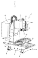
以下、本発明の第1の実施の形態であるマシニングセンタ1について、図面に基づいて説明する。図1は、マシニングセンタ1の正面図である。図2は、スプラッシュカバー3を除いた、マシニングセンタ1の全体斜視図である。図3は、マシニングセンタ1における、工具交換機構20及び主軸ヘッド7を中心とした正面図である。
Hereinafter, a machining center 1 according to a first embodiment of the present invention will be described with reference to the drawings. FIG. 1 is a front view of the machining center 1. FIG. 2 is an overall perspective view of the machining center 1 excluding the splash cover 3. FIG. 3 is a front view of the machining center 1 centering on the
はじめに、マシニングセンタ1の全体構成について説明する。図1に示すように、マシニングセンタ1は、図示外のワーク(図示外)と工具6(図3参照)とを相対移動させて、ワークに所望の機械加工(例えば、「中ぐり」、「フライス削り」、「穴空け」、「切削」等)を施すことができる工作機械である。そして、マシニングセンタ1は、ワークを加工する機械本体と、機械本体の土台となるベッド2と、ベッド2の上部に設けられて機械本体の周囲を囲繞する略直方体状のボックス型のスプラッシュカバー3とを主体に構成されている。
First, the overall configuration of the machining center 1 will be described. As shown in FIG. 1, the machining center 1 moves a workpiece (not shown) and a tool 6 (see FIG. 3) relative to each other to perform desired machining (for example, “boring”, “milling”) on the workpiece. It is a machine tool that can perform cutting, drilling, cutting and the like. The machining center 1 includes a machine body that processes a workpiece, a
図2に示すように、ベッド2は、鉄製の土台であり、その下部の四隅には、脚部2aが各々設けられ、これら4本の脚部2aが工場などの床面に設置されることにより、マシニングセンタ1が所定場所に設置される。さらに、ベッド2の芯部は、軽量化および高強度化のため、いわゆる肉抜き成形(リブによる骨組構造)されている。
As shown in FIG. 2, the
また、図1に示すように、スプラッシュカバー3は、略直方体状のボックス型に形成され、その内側には機械本体によりワーク加工がおこなわれる加工領域が設けられている。スプラッシュカバー3の前面には、開口部を開閉するスライド式の開閉扉4,5が各々設けられている。そして、開閉扉4,5の略中央には、ガラス窓部4a,5aが各々設けられ、開閉扉4の右側端部近傍には取っ手部4bが設けられ、開閉扉5の左側端部近傍には取っ手部5bが設けられている。よって、これら取っ手部4b,5bを互いに離れる方向に開くことにより開口部が開口される。そして、作業者はこの開口部を介して、スプラッシュカバー3の内側に配設されたテーブル10に対して、ワークの着脱を行う。
As shown in FIG. 1, the splash cover 3 is formed in a substantially rectangular parallelepiped box shape, and a machining area in which a workpiece is machined by a machine body is provided inside thereof. On the front surface of the splash cover 3, slide type opening and
なお、図示しないが、スプラッシュカバー3の左右の各側壁部には、メンテナンス用の点検ハッチが着脱可能に各々設けられている。そして、上記構成からなるスプラッシュカバー3は、機械本体の周囲を囲繞して外部より保護するとともに、機械本体から排出される切り屑及び切削液の飛沫等が外部へ飛散するのを遮断して、外部環境が汚染されるのを防止している。 Although not shown, a maintenance inspection hatch is detachably provided on each of the left and right side wall portions of the splash cover 3. And the splash cover 3 having the above configuration surrounds the periphery of the machine body and protects it from the outside, and blocks the chips discharged from the machine body and splashes of the cutting fluid from scattering to the outside. It prevents the external environment from being polluted.
一方、スプラッシュカバー3の正面右側には、マシニングセンタ1の操作をおこなう正面視略長方形状の操作パネル11が設けられている。操作パネル11の前面には、各種キーを備えたキーボード11aが設けられ、その上部には設定画面又は実行動作を表示するためのCRT(ディスプレイ)11bが設けられている。
On the other hand, on the front right side of the splash cover 3, an
次に、マシニングセンタ1の機械本体について説明する。図2に示すように、マシニングセンタ1の機械本体は、スプラッシュカバー3の内側に収納されており、ベッド2のコラム座部17aの上面に載置して固定され、垂直上方に延設された略角柱状のコラム17bと、コラム17bの前面に沿って昇降可能に設けられた主軸ヘッド7と、主軸ヘッド7の下部前側から鉛直下方に突出する主軸9と、主軸ヘッド7の右側に設けられ、主軸9の先端に装着された後述の工具6を、他の工具6に交換する工具交換機構(ATC)20と、ベッド2の上部に設けられてワークを着脱可能に保持するテーブル10と、コラム17bの背面側に設けられ、電源装置や制御基板などの各装置を内蔵する制御盤19とを主体に構成されている。なお、制御盤19の内部には、マシニングセンタ1の制御を司る制御装置(図示外)が配設されている。
Next, the machine body of the machining center 1 will be described. As shown in FIG. 2, the machine body of the machining center 1 is housed inside the splash cover 3, is mounted and fixed on the upper surface of the
そして、コラム17bの前面には、上下方向に延設され、主軸ヘッド7を案内する一対のガイドレール(図示外)が上下方向に固定されている。コラム17bの上面には、サーボモータであるZモータ(図示外)が設けられており、このZモータによりその下方に延設された送りねじ(図示外)が正逆方向へ選択的に回転駆動されて、主軸ヘッド7が上下方向に移動するようになっている。
A pair of guide rails (not shown) extending in the vertical direction and guiding the spindle head 7 are fixed in the vertical direction on the front surface of the
また、主軸ヘッド7には、加工軸に相当する主軸9が回転可能に装着され、主軸9を回転駆動させるための主軸モータ8を上部に備える。そして、主軸9の先端には後述の工具6が着脱可能に装着され、主軸9が主軸モータ8により回転駆動されることによって工具6が回転され、テーブル10上に固定されたワークを加工するようになっている。
A
一方、主軸9の下方には、テーブル10が配設されている。テーブル10は、ワークが着脱自在に固定され、サーボモータからなるXモータ及びYモータ(図示外)により、X軸方向(左右方向)及びY軸方向(奥行き方向)へ移動制御されるものである。テーブル10の下側には略直方体状の支持台12が設けられており、支持台12の上部にはX軸方向に沿って延設された一対のX軸送りガイド(図示外)が設けられて、X軸送りガイド上にテーブル10が移動可能に支持されている。さらに、支持台12は、ベッド2の長手方向に沿って延設された一対のY軸送りガイド上に移動可能に支持されている。このような状態で、テーブル10は、ベッド2上に設けられたXモータにより、X軸送りガイドに沿ってX軸方向に移動し、同じくベッド2上に設けられたYモータにより、Y軸送りガイドに沿ってY軸方向に移動するようになっている。
On the other hand, a table 10 is disposed below the
そして、図3に示すように、工具交換機構20は、工具6が取り付けられた工具ホルダ13を複数格納する側面視略小判型状の工具マガジン30と、主軸9に装着されている工具ホルダ13と他の工具ホルダ13とを把持及び搬送するための工具交換アーム40とを備えている。
As shown in FIG. 3, the
工具交換アーム40は、回転可能および上下動可能に装着された円筒状のアーム旋回軸43の下端部において、その両端部に工具ホルダ13を各々把持可能な把持部41,41が設けられたアーム部42が固定されて構成されている。そして、アーム旋回軸43はZ軸方向と平行をなし、アーム部42はアーム旋回軸43を軸として回動可能である。なお、工具交換アーム40の上部には工具交換モータ24が設けられており、この工具交換モータ24の回転駆動によって、工具交換アーム40の旋回及び上下動が行われる。
The
また、工具マガジン30は、その内側に複数の工具6を各々収納可能な複数の工具ポット31が配設された移送機構(図示外)が装着されており、各工具ポット31では工具ホルダ13に取り付けられた工具6が横方向に向けた状態(格納状態)に維持されている。なお、工具マガジン30の上部にはマガジンモータ26が設けられており、このマガジンモータ26の回転駆動によって、複数の工具ポット31が移送機構により搬送される。
In addition, the
さらに、工具マガジン30の下端側には割出口32が形成され、この割出口32が形成された位置に限り、工具ポット31が格納状態から工具6を下方に向けた状態(交換可能状態)まで回動可能となっている。この工具交換位置には、エアシリンダ(図示外)により駆動されて、工具ポット31を格納状態又は交換可能状態へと回動させるポット昇降機構(図示外)が配設されている。
Further, a
そして、主軸9に装着される工具6の交換時には、工具交換アーム40が原点に上昇されている状態において、まず、工具交換アーム40が旋回し、工具マガジン30側の工具ホルダ13と主軸9に装着された工具ホルダ13とが、把持部41,41でそれぞれ把持される。次いで、工具交換アーム40が下降して、工具抜脱動作が行われる。その後、工具交換アーム40が旋回して主軸9側の工具ホルダ13と工具マガジン30側の工具ホルダ13とが入れ替わる。このとき、工具交換アーム40は180度回転することになる。その後、工具交換アーム40が上昇し、工具交換アーム40に把持された工具6は、工具マガジン30側の工具ポット31あるいは主軸9に装着される。そして、工具交換アーム40が所定角度旋回して、把持部41,41から工具ホルダ13がそれぞれ開放されて、工具交換アーム40のアーム旋回動作の1サイクルが終了する。
When the
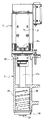
次に、主軸ヘッド7の構成について説明する。図4は、主軸ヘッド7の右方向から見た側面断面拡大図である。図5は、主軸9の右方向から見た側面断面拡大図である。なお、図4は、理解を容易にするために、主軸ヘッド7の軸線上に配置された各部材を中心に表すために、ハウジング25のみを断面図として表している。また、図5では、理解を容易にするために、スピンドル冷却筒60に形成される溝部63(すなわち、冷却路51)の上端を正面視右端に位置させ、その下端を正面視左端に位置させたものを表している。
Next, the configuration of the spindle head 7 will be described. FIG. 4 is an enlarged side cross-sectional view of the spindle head 7 as viewed from the right direction. FIG. 5 is an enlarged side cross-sectional view of the
図4に示すように、主軸ヘッド7の上部には、主軸9が備えるスピンドル27を回転駆動させるための主軸モータ8を備えている。主軸モータ8の下面から下方向に突出する出力軸であるモータ軸8aは、主軸9の内部に設けられたスピンドル27から上方向に突出する入力軸であるスピンドル軸27aに、カップリング50を介して連結されている。かかる構成により、主軸モータ8の駆動によりモータ軸8aが軸線回りに回転すると、カップリング50を介してスピンドル軸27aも回転するため、主軸9のスピンドル27は軸線回りに回転駆動する。
As shown in FIG. 4, a
この主軸モータ8は、図示しないが、円筒状のモータフレーム内に制動部と駆動部を収納した構成をなす。主軸モータ8の駆動部は、インナーロータ形の誘導モータであり、モータ軸8aはロータの内周面に固定されている。また、主軸モータ8の制動部は、モータ軸8aに制動力を加える機械式のディスクブレーキである。
Although not shown, the
また、図4及び図5に示すように、主軸ヘッド7の下部には、先述の主軸9が設けられている。主軸9は、上下方向に長い略円筒状のハウジング25を備えている。そして、そのハウジング25の内側に、正面視縦長筒状のスピンドル冷却筒60が密接に固定されている。スピンドル冷却筒60は、スピンドル27をその内部に収容するとともに、スピンドル27の発熱を冷却するための円筒部材であるが、詳細は後述する。
As shown in FIGS. 4 and 5, the above-described
そして、スピンドル冷却筒60の内部に、スピンドル27が設けられている。詳細には、スピンドル27の軸線方向前端側(下端側)の外周面に、スピンドル27を回転自在に支持するベアリング軸受け30,31が各々設けられている。同様に、スピンドル27の軸線方向後端側(上端側)の外周面に、スピンドル27を回転自在に支持するベアリング軸受け32,33が各々設けられている。また、下端側のベアリング軸受け30,31と上端側のベアリング軸受け32,33に挟持される位置に、スピンドル27の外周を保持する縦長筒状の外筒36が設けられている。そして、これらのベアリング軸受け30〜33や外筒36が設けられたスピンドル27の外周を密接に取り囲むように、スピンドル冷却筒60がその内側に同軸状態でスピンドル27を収容している。そのため、スピンドル27は、スピンドル冷却筒60の内周面に沿ってベアリング軸受け30〜33を介して回転自在に支持される。
A
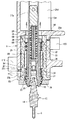
また、スピンドル27の先端部の中心には、テーパ状の内周面を有するホルダ取付穴29が、スピンドル27の軸線に沿って穿設されている。そして、ホルダ取付穴29の内周面に対し、工具ホルダ13のシャンク部14のテーパ状の外周面が密着して嵌まるようになっている。さらに、ホルダ取付穴29の縮径する上部には、このホルダ取付穴29の内周面に連続するとともに、径がやや広くなった広径部34が設けられている。そして、その広径部34の上部には、その広径部34の内周面に連続するとともに、工具ホルダ13側に向かってオイルミスト(高圧空気に微少量のクーラントを混入して霧状にしたもの)を供給するための流路35が設けられている。流路35は軸方向に摺動可能な軸芯28の内部に設けられており、軸芯28はその外周に巻回された皿バネ38によって上方向に付勢されている。
A
さらに、流路35の下部内周面には、複数の鋼球(図示外)を介して工具ホルダ13の上端部に形成されたプルスタッド部15を把持するチャック機構部37が配置されている。なお、ハウジング25の先端側(下端側)には、スピンドル27の先端部を保持するとともに、切削時の切粉等がベアリング軸受け30,31に侵入するのを防止する平面視略リング状の蓋体39が、図示外のボルトによってスピンドル冷却筒60に固定されている。
Further, a
さらに、ハウジング25の軸線方向後端側(上端側)の側面には、その外周方向から軸線に向けて垂直に形成された貫通孔であるエアー流入孔25aが設けられている。一方、ハウジング25の軸線方向前端側(下端側)の側面には、その外周方向から軸線に向けて垂直に形成された貫通孔であるエアー流出孔25bが設けられている。エアー流入孔25a及びエアー流出孔25bは、ハウジング25の内周面とスピンドル冷却筒60の外周面との間隙に形成された螺旋溝状の密閉空間(図7の冷却路51)の上端及び下端に各々連通する位置に形成されているが、詳細は後述する。なお、ハウジング25の外周面におけるエアー流入孔25aの形成部位には、エアー流入孔25aの内部に圧縮空気(冷却エアー)を送るための送風ファン(図示外)などを備えたエアー供給部100が設けられている。エアー供給部100は、制御盤19内に設けられた制御装置(図示外)によって、冷却エアーの供給量や供給圧が制御される。
Further, an
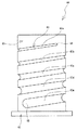
次に、スピンドル冷却筒60について説明する。図6は、スピンドル冷却筒60の正面図である。図6に示すように、スピンドル冷却筒60は正面視縦長筒状の円筒本体61を有する。円筒本体61の内部には、ベアリング軸受け30〜33が取り付けられたスピンドル27を収容可能な貫通孔(図示外)が、その軸線方向(すなわち、上下方向)に形成されている。また、正面視、円筒本体61の下端部には、その開口縁部全周から外周方向に突出したフランジ部62が形成されている。フランジ部62の上面側はハウジング25の下端が接合される部位であり、フランジ部62の下面側は蓋体39の上面が接合される部位である。
Next, the
また、円筒本体61の外周面には、その軸線方向に沿って多重螺旋状に形成された、略半円形の断面形状を有する溝部63が形成されている。本実施形態では、溝部63は軸線方向に沿って約5周回分が連通して形成されており、各周回ごとの溝部を正面視上側から溝部63a,63b,63c,63d,63eとする。そして、溝部63の上端(すなわち、溝部63aの上端)が、後述する冷却エアーが流入されるエアー流入部64であり、溝部63の下端(すなわち、溝部63eの下端)が、後述する冷却エアーが流出されるエアー流出部65である。
Further, on the outer peripheral surface of the cylindrical
そして、溝部63では、互いに隣り合う溝部63a〜63eが形成される間隔(いわゆる、ピッチ)が、エアー流入部64からエアー流出部65に向けて徐々に狭くなるように形成されている。すなわち、正面視、円筒本体61の上側から下側に向けて、互いに隣り合う溝部63a〜63eの間隔(ピッチ)が徐々に小さくなっている。そのため、本実施の形態では、溝部63eと溝部63dとの間隔は溝部63dと溝部63cとの間隔よりも狭く、溝部63dと溝部63cとの間隔は溝部63cと溝部63bとの間隔よりも狭く、溝部63cと溝部63bとの間隔は溝部63bと溝部63aとの間隔よりも狭い。
The
さらに、溝部63では、周回毎の溝部63a〜63eにおける略半円形の溝形状の断面積が、エアー流入部64からエアー流出部65に向けて徐々に大きくなるように形成されている。すなわち、正面視、円筒本体61の上側から下側に向けて、周回毎の溝部63a〜63eにおける略半円形の断面形状が徐々に大きくなっている。そのため、本実施の形態では、溝部63eの断面積は溝部63dの断面積よりも大きく、溝部63dの断面積は溝部63cの断面積よりも大きく、溝部63cの断面積は溝部63bの断面積よりも大きく、溝部63bの断面積は溝部63aの断面積よりも大きい。
Further, the
ここで、スピンドル冷却筒60を用いたスピンドル27の冷却構造について説明する。図7は、第1の実施の形態における冷却エアーの流れを説明するための、主軸9を右方向から見た側面断面拡大図である。なお、図7は、ハウジング25のみを断面図として表しており、冷却エアーの流れを矢印で示している。また、図7では、理解を容易にするために、スピンドル冷却筒60に形成される溝部63(すなわち、冷却路51)の上端を正面視右端に位置させ、その下端を正面視左端に位置させたものを図示している。
Here, a cooling structure of the
図7に示すように、スピンドル冷却筒60がハウジング25の内部に密接固定されると、溝部63はその開口部がハウジング25の内周面によって閉じられるため、スピンドル冷却筒60とハウジング25との間隙に螺旋溝状の密閉空間が形成される。そして、この螺旋溝状の密閉空間が、冷却エアーの流路(冷却路51)として機能する。なお、本実施形態では、溝部63は約5周回分(溝部63a〜63e)が連通して形成されているため、スピンドル冷却筒60がハウジング25の内部に密接固定されると、各溝部63a〜63eにおいて形成される密閉空間はそれぞれ冷却路51a,51b,51c,51d,51eとして機能する。
As shown in FIG. 7, when the
そして、先述した溝部63(溝部63a〜63e)の形状により、冷却路51(冷却路51a〜51e)は以下の特徴を有する。すなわち、冷却路51では、互いに隣り合う冷却路51a〜51eが形成される間隔が、その上端(すなわち、エアー流入部64)からその下端(すなわち、エアー流出部65)に向けて徐々に狭くなっている。また、周回毎の冷却路51a〜51eにおける流路面積(各冷却路の断面積)が、エアー流入部64からエアー流出部65に向けて徐々に大きくなっている。なお、エアー流入部64はエアー流入孔25aと連通しており、かつエアー流出部65はエアー流出孔25bと連通している。
And the cooling path 51 (cooling
かかる構造により、エアー供給部100がハウジング25の外部からエアー流入孔25aの内部に冷却エアーを供給すると、その冷却エアーは冷却路51内でエアー流入部64からエアー流出部65まで流動して、エアー流出孔25bからハウジング25の外部に排出される。つまり、冷却路51内を流動する冷却エアーは、スピンドル27を中心としてその外周を旋回するように、冷却路51a〜51eを上側から下側に向けて流動するため、その流動時にスピンドル27からの発熱が冷却エアーに吸収される。
With this structure, when the
本実施形態のマシニングセンタ1では、上記のようなスピンドル27の冷却機構を有するため、以下の作用を有する。すなわち、冷却路51では、互いに隣り合う冷却路51a〜51eが形成される間隔が冷却エアーの流動方向に向けて徐々に狭くなっているため、スピンドル27の上側に比べて下側の方が冷却エアーの流動距離(流動時間)が長い。よって、冷却エアーが冷却路51内を移動するにつれて、冷却エアーがスピンドル27からの発熱を徐々に吸収する一方、冷却エアーの流動距離(流動時間)が徐々に長くなるので、冷却エアーの冷却効果の低下が流動距離(流動時間)の増加で補われる。
Since the machining center 1 of the present embodiment has the cooling mechanism for the
さらに、冷却路51では、周回毎の冷却路51a〜51eにおける流路面積が冷却エアーの流動方向に向けて徐々に大きくなっているため、スピンドル27の上側に比べて下側の方が冷却エアーの流動面積(スピンドル27の発熱との接触面積)が大きい。よって、冷却エアーが冷却路51内を移動するにつれて、冷却エアーがスピンドル27からの発熱を徐々に吸収する一方、冷却エアーの流動面積(接触面積)が徐々に大きくなるので、冷却エアーの冷却効果の低下が流動面積(接触面積)の増加で補われる。
Furthermore, in the
以上、第1の実施の形態に係るマシニングセンタ1によれば、スピンドル27を冷却するための冷却エアーを冷却路51内に流動させるものであって、冷却路51はスピンドル27の軸線方向に沿って多重螺旋状に形成された。そして、冷却路51はエアー流入部64からエアー流出部65に向けて、互いに隣り合う冷却路51a〜51eの形成される間隔が徐々に狭くなり、また冷却路51a〜51eにおける流路面積が徐々に大きくなるように形成された。よって、冷却路51内を流動する冷却エアーの温度がその流動方向に向けて徐々に上昇しても、冷却エアーの流動距離(流動時間)や流動面積(接触面積)がその流動方向に向けて徐々に大きくなるので、スピンドル27全体を均一に冷却することができる。
As described above, according to the machining center 1 according to the first embodiment, the cooling air for cooling the
また、ハウジング25の内部に、スピンドル27を内部に収容する略円筒状をなし、その外周面に軸線方向に沿って多重螺旋状の溝部63(溝部63a〜63e)が形成されたスピンドル冷却筒60を設けた。そして、冷却路51(冷却路51a〜51e)はスピンドル冷却筒60の外周面とハウジング25の内周面との間隙に形成された。よって、ハウジング25の内部にスピンドル冷却筒60を設ければ、スピンドル27を冷却するための冷却路51を形成することができる。
The
さらに、マシニングセンタ1は、主軸モータ8によって工具6を回転させてワーク加工を実行するものであって、スピンドル27の後端側から冷却エアーを流入させるためにエアー流入孔25aと、スピンドル27の下端側(前端側)から冷却エアーを流出させるためのエアー流出孔25bとを、ハウジング25の側面に形成した。よって、スピンドル27を冷却するための冷却エアーを、ハウジング25の外部からスピンドル27の上端側(後端側)から適切に流入させ、かつスピンドル27の下端側(前端側)からハウジング25の外部に適切に流出させることができる。
Further, the machining center 1 performs workpiece machining by rotating the
次に、本発明の第2の実施の形態であるマシニングセンタ1について、図面に基づいて説明する。本実施形態に係るマシニングセンタ1は、基本的に第1の実施の形態と同様であるが、スピンドル冷却筒70の構造及び冷却エアーの排出部位が異なる。以下、第1の実施の形態と異なる点を中心に説明する。
Next, the machining center 1 which is the 2nd Embodiment of this invention is demonstrated based on drawing. The machining center 1 according to this embodiment is basically the same as that of the first embodiment, but the structure of the
まず、スピンドル冷却筒70について説明する。図8は、スピンドル冷却筒70の正面図である。図8に示すように、スピンドル冷却筒70は、スピンドル冷却筒60(図6)と同様に、円筒本体71,フランジ部72,溝部73を有する。ただし、本実施形態では、溝部73は軸線方向に沿って約6周回分が連通して形成されており、各周回ごとの溝部を正面視上側から溝部73a,73b,73c,73d,73e,73fとする。そして、溝部63の上端(すなわち、溝部73aの上端)が、後述する冷却エアーが流入されるエアー流入部74であり、溝部73の下端(すなわち、溝部73fの下端)が、後述する冷却エアーが流出されるエアー流出部75である。
First, the
そして、溝部73では、スピンドル冷却筒60(図6)と同様にして、互いに隣り合う溝部73a〜73fが形成される間隔が、エアー流入部74からエアー流出部75に向けて徐々に狭くなるように形成されている。また、溝部73では、周回毎の溝部73a〜73fにおける略半円形の溝形状の断面積が、エアー流入部74からエアー流出部75に向けて徐々に大きくなるように形成されている。さらに、円筒本体71には、その下面から垂直に形成された貫通孔であって、エアー流出部75と連通するエアー流出孔76が形成されている。
Then, in the
次に、スピンドル冷却筒70を用いたスピンドル27の冷却構造について説明する。図9及び図10は、第2の実施の形態における冷却エアーの流れを説明するための、主軸9を右方向から見た側面断面拡大図である。なお、図9はハウジング25のみを断面図として表し、図10はハウジング25及びスピンドル冷却筒70を断面図として表し、冷却エアーの流れを矢印で表している。また、図9及び図10では、理解を容易にするために、スピンドル冷却筒70に形成される溝部73(すなわち、冷却路52)の上端を正面視右端に位置させ、その下端を正面視左端に位置させたものを図示している。
Next, the cooling structure of the
図9及び図10に示すように、スピンドル冷却筒70がハウジング25の内部に密接固定されると、溝部73はその開口部がハウジング25の内周面によって閉じられるため、スピンドル冷却筒70とハウジング25との間隙に螺旋溝状の密閉空間が形成される。そして、この螺旋溝状の密閉空間が、冷却エアーの流路(冷却路52)として機能する。なお、本実施形態では、溝部73は約6周回分(溝部73a〜73f)が連通して形成されているため、スピンドル冷却筒70がハウジング25の内部に密接固定されると、各溝部73a〜73fにおいて形成される密閉空間はそれぞれ冷却路52a〜52fとして機能する。
As shown in FIGS. 9 and 10, when the
そして、第1の実施の形態と同様に、冷却路52では、互いに隣り合う冷却路52a〜52fが形成される間隔が、その上端(すなわち、エアー流入部74)からその下端(すなわち、エアー流出部75)に向けて徐々に狭くなっている。また、周回毎の冷却路52a〜52fにおける流路面積が、エアー流入部74からエアー流出部75に向けて徐々に大きくなっている。
As in the first embodiment, in the
なお、本実施の形態では、ハウジング25にはエアー流入孔25aのみが設けられている(エアー流出孔25bは設けられていない)。そして、エアー流入部74はエアー流入孔25aと連通している一方、エアー流出部75は先述のエアー流出孔76と連通している。このエアー流出孔76は蓋体39の上面に形成された貫通孔であるエアー導出路39aの一端部と連通し、このエアー導出路39aの他端部は蓋体39の内周面に連通している。つまり、エアー流出部75はエアー流出孔76及びエアー導出路39aを介して、スピンドル27の軸線方向前端側(下端側)の外周面と蓋体39の内周面との間隙に連通している。
In the present embodiment, the
かかる構造により、エアー供給部100がハウジング25の外部からエアー流入孔25aの内部に冷却エアーを供給すると、その冷却エアーは冷却路52内でエアー流入部74からエアー流出部75まで流動して、エアー流出孔76及びエアー導出路39aを介して、スピンドル27の下端側の外周面と蓋体39の内周面との間隙に導出される。そして、導出された冷却エアーは、スピンドル27及び蓋体39の間隙からスピンドル27の下方向に排出される。つまり、冷却路52内を流動する冷却エアーは、スピンドル27を中心としてその外周を旋回するように、冷却路52a〜52fを上側から下側に向けて流動す
るため、その流動時にスピンドル27からの発熱が冷却エアーに吸収される。
With this structure, when the
本実施形態のマシニングセンタ1では、上記のようなスピンドル27の冷却機構を有するため、以下の作用を有する。すなわち、第1の実施の形態と同様に、冷却路52内を冷却エアーが流動するにつれて、冷却エアーがスピンドル27からの発熱を徐々に吸収する一方、冷却エアーの流動距離(流動時間)が徐々に長くなり、かつ冷却エアーの流動面積(接触面積)が徐々に大きくなる。
Since the machining center 1 of the present embodiment has the cooling mechanism for the
さらに、冷却路52内を流動する冷却エアーは、エアー流出孔76及びエアー導出路39aを介して、スピンドル27の下端側の外周面と蓋体39の内周面との間隙から排出される。つまり、冷却エアーがスピンドル27の下端部に形成された隙間から排出されるので、スピンドル27と蓋体39との隙間に対するゴミやほこりなどの侵入が防止される。
Further, the cooling air flowing in the
以上、第2の実施の形態に係るマシニングセンタ1によれば、スピンドル27とスピンドル冷却筒70との間隙に形成される冷却路52は、スピンドル冷却筒70に形成された溝部73に応じて、その周回数,形成幅,流路面積などを任意に変更することができる。そして、第1の実施の形態と同様に、冷却路52内を流動する冷却エアーの温度がその流動方向に向けて徐々に上昇しても、冷却エアーの流動距離(流動時間)や流動面積(接触面積)がその流動方向に向けて徐々に大きくなるので、スピンドル27全体を均一に冷却することができる。
As described above, according to the machining center 1 according to the second embodiment, the cooling
さらに、マシニングセンタ1は、スピンドル27の下端部(前端部)は蓋体39の内周面に回転自在に支持されており、エアー流出孔76及びエアー導出路39aはスピンドル27の下端部(前端部)の外周面と蓋体39の内周面との間隙に冷却エアーを供給する。よって、冷却路52を流動した冷却エアーをスピンドル27の下端部(前端部)に形成された隙間から排出できるので、スピンドル27から異物をエアパージすることができる。
Further, in the machining center 1, the lower end portion (front end portion) of the
次に、本発明の第3の実施の形態であるマシニングセンタ1について、図面に基づいて説明する。本実施形態に係るマシニングセンタ1は、基本的に第1及び第2の実施の形態と同様であるが、スピンドル冷却筒80の構造及び冷却エアーの排出部位が異なる。以下、第1及び第2の実施の形態と異なる点を中心に説明する。
Next, the machining center 1 which is the 3rd Embodiment of this invention is demonstrated based on drawing. The machining center 1 according to the present embodiment is basically the same as the first and second embodiments, but the structure of the
まず、スピンドル冷却筒80について説明する。図11は、スピンドル冷却筒80の正面図である。図8に示すように、スピンドル冷却筒80は、スピンドル冷却筒60(図6)と同様に、円筒本体81,フランジ部82を有する。そして、本実施形態では、円筒本体81の外周面には、その軸線方向に沿って多重螺旋状に形成された、略半円形の断面形状を有する2つの第1溝部83及び第2溝部86が形成されている。第1溝部83は軸線方向に沿って約5周回分が連通して形成されており、第2溝部86は軸線方向に沿って約4周回分が連通して形成されている。そして、円筒本体81の外周面において、第1溝部83の各周回と第2溝部86の各周回とは上下方向に交互に形成されている。
First, the
なお、第1溝部83における各周回ごとの溝部を正面視上側から第1溝部83a,83b,83c,83d,83eとする。そして、第1溝部83の上端(すなわち、第1溝部83aの上端)が、冷却エアーが流入される第1エアー流入部84であり、第1溝部83の下端(すなわち、第1溝部83eの下端)が、冷却エアーが流出される第1エアー流出部85である。一方、第2溝部86における各周回ごとの溝部を正面視下側から第2溝部86a,86b,86c,86dとする。そして、第2溝部86の下端(すなわち、第2溝部86aの下端)が、冷却エアーが流入される第2エアー流入部87であり、第2溝部86の上端(すなわち、第2溝部86dの上端)が、冷却エアーが流出される第2エアー流出部88である。
In addition, let the groove part for every round in the
そして、第1溝部83では、スピンドル冷却筒60(図6)と同様にして、第1エアー流入部84から第1エアー流出部85に向けて、互いに隣り合う第1溝部83a〜83eが形成される間隔が徐々に狭くなっており、また周回毎の第1溝部83a〜83eにおける略半円形の溝形状の断面積が徐々に大きくなっている。同様に、第2溝部86では、第2エアー流入部87から第2エアー流出部88に向けて、互いに隣り合う第2溝部86a〜86dが形成される間隔が徐々に狭くなっており、また周回毎の第2溝部86a〜86dにおける略半円形の溝形状の断面積が徐々に大きくなっている。つまり、第1溝部83と第2溝部86とは、各々が対向する方向に向けて交互に重複なく形成されつつ、各々の形成間隔が徐々に小さくなっており、かつ各々の断面積が徐々に大きくなっている。なお、円筒本体81には、その上面から垂直に形成された貫通孔であって、第2エアー流出部88と連通するエアー流出孔89が形成されている。
Then, in the
次に、スピンドル冷却筒80を用いたスピンドル27の冷却構造について説明する。図12及び図13は、第3の実施の形態における冷却エアーの流れを説明するための、主軸9を右方向から見た側面断面拡大図である。なお、図12はハウジング25のみを断面図として表し、図13はハウジング25及びスピンドル冷却筒80を断面図として表し、冷却エアーの流れを矢印で表している。また、図12及び図13では、理解を容易にするために、スピンドル冷却筒80に形成される第1溝部83(すなわち、第1冷却路53)の上端を正面視右端に位置させ、その下端を正面視左端に位置させており、また第2溝部86(すなわち、第2冷却路54)の上端を正面視左端に位置させ、その下端を正面視左端に位置させたものを図示している。
Next, the cooling structure of the
図12及び図13に示すように、スピンドル冷却筒80がハウジング25の内部に密接固定されると、第1溝部83及び第2溝部86は各々の開口部がハウジング25の内周面によって閉じられるため、スピンドル冷却筒80とハウジング25との間隙に2つの独立した螺旋溝状の密閉空間を形成する。そして、この2つの螺旋溝状の密閉空間が、冷却エアーの流路(第1冷却路53及び第2冷却路54)として機能する。なお、本実施形態では、第1溝部83は約5周回分(溝部83a〜83e)が連通して形成されているため、スピンドル冷却筒80がハウジング25の内部に密接固定されると、各第1溝部83a〜83eにおいて形成される密閉空間はそれぞれ第1冷却路53a〜53eとして機能する。また、第2溝部86は約4周回分(第2溝部86a〜86d)が連通して形成されているため、スピンドル冷却筒80がハウジング25の内部に密接固定されると、各第2溝部86a〜86dにおいて形成される密閉空間はそれぞれ第2冷却路54a〜54dとして機能する。
As shown in FIGS. 12 and 13, when the
このように第1冷却路53及び第2冷却路54は、スピンドル27の軸線方向に沿って多重螺旋状で形成されており、また第1冷却路53及び第2冷却路54の各々が重複しないように間隔をあけて交互に形成されている。つまり、ハウジング25の外周面では、その軸線方向後端側(上端側)から軸線方向前端側(下端側)に向けて第1冷却路53a〜53eが順に形成され、その逆方向に向けて第2冷却路54a〜54dが順に形成され、かつ第1冷却路53a〜53eと第2冷却路54a〜54dが間隔をあけて並列に形成されている。よって、ハウジング25の外周面に形成された第1冷却路53及び第2冷却路54は、各々が接触(交差)することなく独立した冷却エアーの流路を形成している。
As described above, the
そして、第1の実施の形態と同様に、第1冷却路53では第1エアー流入部84から第1エアー流出部85に向けて、互いに隣り合う第1冷却路53a〜53eの形成間隔が徐々に狭くなっており、周回毎の第1冷却路53a〜53eにおける流路面積が徐々に大きくなっている。また、第2冷却路54では第2エアー流入部87から第2エアー流出部88に向けて、互いに隣り合う第2冷却路54a〜54dの形成間隔が徐々に狭くなっており、周回毎の第2冷却路54a〜54dにおける流路面積が徐々に大きくなっている。
As in the first embodiment, in the
なお、本実施の形態では、ハウジング25の側面には、エアー流入孔25a及びエアー流出孔25bに加えて、その軸線方向前端側(下端側)にその外周方向から軸線に向けて垂直に形成された貫通孔であるエアー流入孔25cが設けられている。そして、ハウジング25の外周面におけるエアー流入孔25cの形成部位には、エアー流入孔25aに設けられたエアー供給部100と同様に、エアー供給部110が設けられている。そして、第1エアー流入部84はエアー流入孔25aと連通している一方、第1エアー流出部85はエアー流出孔25bと連通している。また、第2エアー流入部87はエアー流入孔25cと連通している一方、第2エアー流出部88は先述のエアー流出孔89と連通している。このエアー流出孔89は、スピンドル冷却筒80の軸線方向後端面(上面)とハウジング25の内周面との間隙に連通している。
In the present embodiment, in addition to the
かかる構造により、エアー供給部100がハウジング25の外部からエアー流入孔25aの内部に冷却エアーを供給すると、その冷却エアーは第1冷却路53内で第1エアー流入部84から第1エアー流出部85まで流動して、エアー流出孔25bからハウジング25の外部に排出される。つまり、第1冷却路53内を流動する冷却エアーは、スピンドル27を中心としてその外周を旋回するように第1冷却路53a〜53eを上側から下側に向けて流動するため、その流動時にスピンドル27からの発熱が冷却エアーに吸収される。
With this structure, when the
さらに、エアー供給部110がハウジング25の外部からエアー流入孔25cの内部に冷却エアーを供給すると、その冷却エアーは第2冷却路54内で第2エアー流入部87から第2エアー流出部88まで流動して、エアー流出孔89を介してスピンドル27の上面とハウジング25の内周面との間隙に導出される。そして、導出された冷却エアーは、スピンドル27及びハウジング25の間隙からスピンドル27の上方向に排出される。つまり、第2冷却路54内を流動する冷却エアーは、スピンドル27を中心としてその外周を旋回するように第2冷却路54a〜54dを下側から上側に向けて流動するため、その流動時にスピンドル27からの発熱が冷却エアーに吸収される。
Further, when the
本実施形態のマシニングセンタ1では、上記のようなスピンドル27の冷却機構を有するため、以下の作用を有する。すなわち、スピンドル27の軸線方向に沿って、2つの多重螺旋状のエアー流路である第1冷却路53及び第2冷却路54が、各々が重複しないように間隔をあけて形成された。そして、第1冷却路53では第1エアー流入部84から第1エアー流出部85に向けて冷却エアーが流動し、第2冷却路54では第2エアー流入部87から第2エアー流出部88に向けて冷却媒体が流動する。よって、スピンドル27の軸線方向(すなわち、上下方向)の両側から、その外周を冷却エアーが各々対向する方向に向けて螺旋状に流動する。
Since the machining center 1 of the present embodiment has the cooling mechanism for the
さらに、第1の実施の形態と同様に、第1冷却路53内及び第2冷却路54内を冷却エアーが流動するにつれて、冷却エアーがスピンドル27からの発熱を徐々に吸収する一方、冷却エアーの流動距離(流動時間)が徐々に長くなり、かつ冷却エアーの流動面積(接触面積)が徐々に大きくなる。
Further, as in the first embodiment, as the cooling air flows in the
また、第2冷却路54内を流動する冷却エアーは、エアー流出孔89を介して、スピンドル27の上面とハウジング25の内周面との間隙から排出される。つまり、冷却エアーがスピンドル27の上端部に形成された隙間から排出されるので、スピンドル27とハウジング25との隙間に対するゴミやほこりなどの侵入が防止され、またスピンドル27の後端部から排出された冷却エアーはハウジング25の開口部25dから外部に導出される。
The cooling air flowing in the
以上、第3の実施の形態に係るマシニングセンタ1によれば、スピンドル27を冷却するための冷却エアーを第1冷却路53及び第2冷却路54内に流動させるものであって、第1冷却路53ではスピンドル27の後端側から前端側に向けて冷却エアーが流動し、第2冷却路54ではスピンドル27の前端側から後端側に向けて冷却媒体が流動する。さらに、第1冷却路53及び第2冷却路54は、スピンドル27の軸線方向に沿って多重螺旋状で形成され、かつ各々が重複しないように間隔をあけて形成された。よって、第1冷却路53及び第2冷却路54内を流動する冷却エアーの温度がその流動方向に向けて徐々に上昇しても、スピンドル27の全周に形成された流動方向の異なる第1冷却路53及び第2冷却路54を冷却エアーは各々対向する方向に流動するため、スピンドル27の全体を均一に冷却することができる。
As described above, according to the machining center 1 according to the third embodiment, the cooling air for cooling the
また、スピンドル27とスピンドル冷却筒80との間隙に形成される複数の冷却路(第1冷却路53及び第2冷却路54)は、スピンドル冷却筒80に形成された第1溝部83及び第2溝部86に応じて、その周回数,形成幅,流路面積などを任意に変更することができ、またその形成数(ここでは、2つ)を任意に変更することができる。そして、第1及び第2の実施の形態と同様に、第1冷却路53及び第2冷却路54内を流動する冷却エアーの温度がその流動方向に向けて徐々に上昇しても、冷却エアーの流動距離(流動時間)や流動面積(接触面積)がその流動方向に向けて徐々に大きくなるので、スピンドル27全体を均一に冷却することができる。
A plurality of cooling paths (first cooling
また、マシニングセンタ1は、スピンドル27の上端部(後端部)はハウジング25の内周面に取り付けられて、エアー流出孔89はスピンドル27の上面(後端面)とハウジング25の内周面との間隙に冷却エアーを供給する。よって、第2冷却路54内を流動した冷却エアーをスピンドル27の上端部(後端部)に形成された隙間から排出できるので、主軸9から異物をエアパージすることができる。
In the machining center 1, the upper end (rear end) of the
ところで、上記第1乃至第3の実施の形態において、マシニングセンタ1が本発明の「工作機械のスピンドル冷却装置」に相当し、冷却エアーが本発明の「冷却媒体」に相当する。スピンドル冷却筒60,70,80が、本発明の「スピンドル冷却部材」に相当する。エアー供給部100,110が、本発明の「冷却媒体供給手段」に相当する。エアー流入孔25a,25cが本発明の「冷却媒体流入部」に相当し、エアー流出孔25b,エアー流出孔76及びエアー導出路39aが本発明の「冷却媒体流出部」に相当する。
In the first to third embodiments, the machining center 1 corresponds to the “spindle cooling device for a machine tool” according to the present invention, and the cooling air corresponds to the “cooling medium” according to the present invention. The
なお、本発明は上記実施の形態に限定されることはなく、本発明の要旨を逸脱しない範囲内で種々の改良、変形が可能であることは勿論である。図14は、スピンドル冷却筒60の変形例の正面図である。図15は、環状ホルダ90を備えた主軸9のホルダ取付穴29を中心とした側面断面拡大図である。
In addition, this invention is not limited to the said embodiment, Of course, various improvement and deformation | transformation are possible within the range which does not deviate from the summary of this invention. FIG. 14 is a front view of a modified example of the
例えば、図14に示すように、スピンドル冷却筒60の円筒本体61の外周面に、溝部63の縁部に沿ってゴム製パッキンであるパッキング部材(パッキン69)を設けるようにしてもよい。このスピンドル冷却筒60をハウジング25の内部に取り付けると、パッキン69によってスピンドル冷却筒60の外周面とハウジング25の内周面とがより密接に固定されるため、冷却路51を流動する冷却エアーが、スピンドル冷却筒60とハウジング25の間隙に漏れ出すことが防止される。よって、冷却路51を流動する冷却エアーの漏出を確実に防止でき、冷却エアーによるスピンドル27の冷却効果を向上させることができる。なお、スピンドル冷却筒70,80についても、同様の「パッキング部材」を設けることができる。
For example, as shown in FIG. 14, a packing member (packing 69) that is a rubber packing may be provided along the edge of the
また、図15に示すように、主軸9の軸線方向前端部(下端部)に、蓋体39の下部に環状ホルダ90を設けるようにしてもよい。この環状ホルダ90は、平面視略リング状をなし、複数の一体型ノズル91及びノズル孔92が形成されている。そして、主軸9に取り付けられる工具6の交換時に、図示外のクーラントホースから各一体型ノズル91に供給されたクーラント液が、各ノズル孔92からホルダ取付穴29の直下に向けて噴射されて、工具ホルダ13(工具6)が洗浄される。そして、制御盤19内の制御装置(図示外)は、マシニングセンタ1の運転中及び運転停止後の所定時間と、環状ホルダ90におけるクーラント液の噴射中及び噴射停止後の所定時間との少なくとも一方のみに、エアー供給部100が冷却エアーを供給するように制御してもよい。これにより、スピンドル27が発熱しやすいマシニングセンタ1の運転動作及び工具6の洗浄動作の実行時に対応して、冷却エアーの供給時期を適切に調整することができる。
As shown in FIG. 15, an
なお、制御装置(図示外)による冷却エアーの供給制御は、上記のものに限定されず、様々な方式を適用できる。例えば、制御盤19内の制御装置(図示外)は、主軸モータ8に供給される電流量に基づいて、エアー供給部100が供給する冷却エアーの供給量及び供給圧の少なくとも一つを制御するようにしてもよい。さらに、制御盤19内の制御装置(図示外)は、スピンドル27の温度に基づいて、エアー供給部100が供給する冷却エアーの供給量及び供給圧の少なくとも一つを制御するようにしてもよい。これにより、主軸モータ8の駆動やスピンドル27の温度などに基づいて、冷却エアーの供給量及び供給圧を適切に調整することができる。なお、エアー供給部110についても同様にして冷却エアーの供給制御を実行することができる。
The cooling air supply control by the control device (not shown) is not limited to the above, and various methods can be applied. For example, a control device (not shown) in the
また、上記第1乃至第3の実施の形態に係るマシニングセンタ1を、任意に組み合わせても実装してもよい。例えば、第3の実施の形態に係るマシニングセンタ1において、
第1エアー流出部85から流出する冷却エアーを、第2の実施の形態のようにスピンドル27の前端側(下端側)から排出するようにしてもよいし、第2エアー流出部88から流出する冷却エアーを、第1の実施の形態のようにハウジング25の側面から外部に排出するようにしてもよい。
Further, the machining centers 1 according to the first to third embodiments may be arbitrarily combined or mounted. For example, in the machining center 1 according to the third embodiment,
The cooling air flowing out from the first
また、第3の実施の形態で例示したように、マシニングセンタ1に複数の冷却路を設ける場合は、冷却路の数量,形成方向,形状などを任意とすることができる。例えば、スピンドル冷却筒80にあらかじめ各冷却路に対応する各溝部を形成することで、マシニングセンタ1に3以上の冷却路を設けてもよいし、各冷却路の形状を波型や直線状となるようにしてもよい。
Further, as exemplified in the third embodiment, when a plurality of cooling paths are provided in the machining center 1, the number, the forming direction, and the shape of the cooling paths can be arbitrarily set. For example, by forming grooves corresponding to the respective cooling paths in the
また、上記実施の形態では、「冷却媒体」として圧縮空気(冷却エアー)を例示したが、スピンドル27を有効に冷却できるものであれば、各種媒体を利用することができる。例えば、「冷却媒体」として、窒素やヘリウムなどの他の気体を利用してもよいし、水やオイルなどの液体を利用してもよい。
In the above embodiment, compressed air (cooling air) is exemplified as the “cooling medium”, but various media can be used as long as the
本発明の工作機械のスピンドル冷却装置は、冷却媒体によってスピンドルを冷却する工作機械に適用することができる。 The spindle cooling device for a machine tool of the present invention can be applied to a machine tool that cools a spindle with a cooling medium.
1 マシニングセンタ
7 主軸ヘッド
8 主軸モータ
9 主軸
19 制御盤
25 ハウジング
25a エアー流入孔
25b エアー流出孔
25c エアー流入孔
25d 開口部
27 スピンドル
39 蓋体
39a エアー導出路
51a,51b,51c,51d,51e 冷却路
52a,52b,52c,52d,52e,52f 冷却路
53a,53b,53c,53d,53e 第1冷却路
54a,54b,54c,54d 第2冷却路
60 スピンドル冷却筒
63a,63b,63c,63d,63e 溝部
64 エアー流入部
65 エアー流出部
69 パッキン
70 スピンドル冷却筒
73a,73b,73c,73d,73e,73f 溝部
73a 溝部
74 エアー流入部
75 エアー流出部
76 エアー流出孔
80 スピンドル冷却筒
83a,83b,83c,83d,83e 第1溝部
84 第1エアー流入部
85 第1エアー流出部
86a,86b,86c,83d 第2溝部
87 第2エアー流入部
88 第2エアー流出部
89 エアー流出孔
90 環状ホルダ
100,110 エアー供給部
1 Machining Center 7
Claims (9)
前記冷却媒体流出部は、前記冷却媒体の流動面積が前記冷却媒体流入部より大きく形成され、
前記複数の冷却路は、前記スピンドルの一端側から他端側に向けて前記冷却媒体が流動する流路と、前記スピンドルの他端側から一端側に向けて前記冷却媒体が流動する流路とからなり、
前記複数の冷却路の各々は、該冷却路の前記冷却媒体流入部から該冷却路の前記冷却媒体流出部に向けて、その流路面積が徐々に大きくなるように形成されたことを特徴とする工作機械のスピンドル冷却装置。 A spindle rotatably supported through a bearing inside the housing, cooling medium supply means for supplying a cooling medium for cooling the spindle, and a flow path for the cooling medium provided in the outer peripheral direction of the spindle A plurality of cooling paths, a plurality of cooling medium inflow portions for allowing the cooling medium to flow into one end of the plurality of cooling paths from the outside of the housing, and the housing from the other end of the plurality of cooling paths. A spindle cooling device for a machine tool, comprising a plurality of cooling medium outflow portions for flowing out the cooling medium to the outside,
The cooling medium outflow portion is formed such that a flow area of the cooling medium is larger than the cooling medium inflow portion,
The plurality of cooling paths include a flow path through which the cooling medium flows from one end side to the other end side of the spindle, and a flow path through which the cooling medium flows from the other end side to the one end side of the spindle. Consists of
Each of the plurality of cooling passages is formed such that the flow passage area gradually increases from the cooling medium inflow portion of the cooling passage toward the cooling medium outflow portion of the cooling passage. Spindle cooling device for machine tools.
前記スピンドル冷却部材の外面には、その軸線方向に沿って多重螺旋状の溝部が複数形成されており、
前記複数の冷却路は、前記スピンドル冷却部材と前記ハウジングとの間隙に形成されたことを特徴とする請求項1又は2に記載の工作機械のスピンドル冷却装置。 A spindle cooling member that houses the spindle inside is provided in the housing.
On the outer surface of the spindle cooling member, a plurality of multiple spiral grooves are formed along the axial direction thereof.
The spindle cooling device for a machine tool according to claim 1, wherein the plurality of cooling paths are formed in a gap between the spindle cooling member and the housing.
前記複数の冷却媒体流入部は、前記スピンドルの一端側又は他端側から前記冷却媒体を各々流入させるための前記冷却媒体の流路であり、
前記複数の冷却媒体流出部は、前記スピンドルの他端側又は一端側から前記冷却媒体を各々流出させるための前記冷却媒体の流路であることを特徴とする請求項1乃至4のいずれかに記載の工作機械のスピンドル冷却装置。 In the machine tool, a tool is attached to and detached from one end portion of the spindle, and a motor is connected to the other end portion of the spindle, and the tool fitted on the spindle is rotated by the motor to perform workpiece machining. To do,
The plurality of cooling medium inflow portions are flow paths of the cooling medium for allowing the cooling medium to flow from one end side or the other end side of the spindle,
The plurality of cooling medium outflow portions are flow paths of the cooling medium for allowing the cooling medium to flow out from the other end side or one end side of the spindle, respectively. The spindle cooling device for the machine tool described.
前記複数の冷却媒体流出部の少なくとも一つは、前記スピンドルの一端部の外周面と前記蓋体の内周面との間隙に前記冷却媒体を供給し、前記スピンドルの一端部に形成された隙間を経由して前記冷却媒体を排出させることを特徴とする請求項5に記載の工作機械のスピンドル冷却装置。 One end of the spindle is rotatably supported on the inner peripheral surface of a ring-shaped lid that prevents intrusion of foreign matter,
At least one of the plurality of cooling medium outflow portions supplies the cooling medium to a gap between an outer peripheral surface of one end of the spindle and an inner peripheral surface of the lid, and a gap formed at one end of the spindle The spindle cooling device for a machine tool according to claim 5, wherein the cooling medium is discharged through the machine tool.
前記冷却媒体供給手段は、前記工作機械の運転中及び運転停止後の所定時間と、前記工具洗浄手段によるクーラント液の噴射中及び噴射停止後の所定時間との少なくとも一方のみに、前記冷却媒体を供給することを特徴とする請求項5乃至7のいずれかに記載の工作機械のスピンドル冷却装置。 A tool cleaning means for cleaning the tool by spraying a coolant liquid onto the tool attached to and detached from the spindle;
The cooling medium supply means supplies the cooling medium only to at least one of a predetermined time during operation of the machine tool and after operation stop and a predetermined time after injection of the coolant liquid by the tool cleaning means and after injection stop. The spindle cooling device for a machine tool according to any one of claims 5 to 7, wherein the spindle cooling device is supplied.
Priority Applications (1)
| Application Number | Priority Date | Filing Date | Title |
|---|---|---|---|
| JP2006071775A JP4865371B2 (en) | 2006-03-15 | 2006-03-15 | Spindle cooling device for machine tools |
Applications Claiming Priority (1)
| Application Number | Priority Date | Filing Date | Title |
|---|---|---|---|
| JP2006071775A JP4865371B2 (en) | 2006-03-15 | 2006-03-15 | Spindle cooling device for machine tools |
Publications (2)
| Publication Number | Publication Date |
|---|---|
| JP2007245286A JP2007245286A (en) | 2007-09-27 |
| JP4865371B2 true JP4865371B2 (en) | 2012-02-01 |
Family
ID=38590104
Family Applications (1)
| Application Number | Title | Priority Date | Filing Date |
|---|---|---|---|
| JP2006071775A Active JP4865371B2 (en) | 2006-03-15 | 2006-03-15 | Spindle cooling device for machine tools |
Country Status (1)
| Country | Link |
|---|---|
| JP (1) | JP4865371B2 (en) |
Families Citing this family (13)
| Publication number | Priority date | Publication date | Assignee | Title |
|---|---|---|---|---|
| JP5851309B2 (en) * | 2012-03-30 | 2016-02-03 | シチズンホールディングス株式会社 | Spindle cooling holder device and spindle cooling device |
| JP6492459B2 (en) * | 2014-02-28 | 2019-04-10 | 日本精工株式会社 | Spindle device |
| JP6451146B2 (en) * | 2014-02-28 | 2019-01-16 | 日本精工株式会社 | Spindle device |
| JP6484960B2 (en) * | 2014-02-28 | 2019-03-20 | 日本精工株式会社 | Spindle device |
| KR101917016B1 (en) * | 2014-02-28 | 2018-11-08 | 닛본 세이고 가부시끼가이샤 | Main shaft device |
| WO2015129826A1 (en) * | 2014-02-28 | 2015-09-03 | 日本精工株式会社 | Main shaft device |
| JP6451147B2 (en) * | 2014-02-28 | 2019-01-16 | 日本精工株式会社 | Spindle device |
| JP2015186829A (en) * | 2014-03-26 | 2015-10-29 | 三菱重工業株式会社 | Cooling structure of machine tool |
| CN105798701B (en) * | 2016-05-11 | 2019-07-23 | 西安交通大学 | A kind of high speed based on pulsating heat pipe cooling structure, high precision electro main shaft |
| CN106870563A (en) * | 2017-02-28 | 2017-06-20 | 浙江大学 | Hyperboloid spiral grooved bearing |
| KR102146611B1 (en) * | 2018-10-26 | 2020-08-20 | 현대위아 주식회사 | Spindle head of working machine |
| CN114309680A (en) * | 2022-01-13 | 2022-04-12 | 珠海格力电器股份有限公司 | Cooling assembly and electric spindle with same |
| CN117381020B (en) * | 2023-12-13 | 2024-02-20 | 成都易格机械有限责任公司 | Precise machining device and method for annular groove of special-shaped shell |
Family Cites Families (5)
| Publication number | Priority date | Publication date | Assignee | Title |
|---|---|---|---|---|
| JPH05208339A (en) * | 1992-01-29 | 1993-08-20 | Osaka Kiko Co Ltd | Temperature control device for spindle of machine tool |
| JPH08197375A (en) * | 1995-01-18 | 1996-08-06 | Okuma Mach Works Ltd | Fluid circulating device on spindle head |
| JPH1190762A (en) * | 1997-05-27 | 1999-04-06 | Chiron Werke Gmbh & Co Kg | Machine tool |
| JP2000354937A (en) * | 1999-06-11 | 2000-12-26 | Mori Seiki Co Ltd | Fluid supplying device for machine tool |
| JP4553422B2 (en) * | 1999-09-06 | 2010-09-29 | 株式会社松浦機械製作所 | Cooling control device for rotating shaft |
-
2006
- 2006-03-15 JP JP2006071775A patent/JP4865371B2/en active Active
Also Published As
| Publication number | Publication date |
|---|---|
| JP2007245286A (en) | 2007-09-27 |
Similar Documents
| Publication | Publication Date | Title |
|---|---|---|
| JP4865371B2 (en) | Spindle cooling device for machine tools | |
| JP2007245285A (en) | Device for cooling main spindle of machine tool | |
| JP4958300B2 (en) | Machine Tools | |
| JP5951018B2 (en) | EDM method | |
| JP4061553B2 (en) | Machine Tools | |
| JP4745612B2 (en) | Machine Tools | |
| JP2008264891A (en) | Universal head and machine tool equipped with it | |
| JP5026884B2 (en) | Machine tool with automatic tool changer | |
| WO2006100898A1 (en) | Machine tool | |
| JP5548530B2 (en) | Tools and machine tools | |
| JP2009113170A5 (en) | ||
| CN108367403A (en) | Complex machining device and combined machining method | |
| JP2005334920A (en) | Tool-changing magazine in laser beam machine | |
| JP2010023202A (en) | Numerical value control type machine tool, and air pressure switching method for numerical value control type machine tool | |
| JP6688829B2 (en) | Machine Tools | |
| JP4375048B2 (en) | Machine Tools | |
| JP4710295B2 (en) | Machine Tools | |
| JP2009291848A (en) | Machine tool | |
| JP6850934B1 (en) | Processing machine | |
| JP2002331430A (en) | Machine tool | |
| JP5019944B2 (en) | Machine Tools | |
| JP4555675B2 (en) | Machine Tools | |
| JP2007182947A (en) | Coupling, machine tool provided with it, and method of aligning axial center | |
| KR20180029828A (en) | machine tool having a multiple spindle head | |
| JP2018075673A (en) | Multispindle machine tool |
Legal Events
| Date | Code | Title | Description |
|---|---|---|---|
| RD04 | Notification of resignation of power of attorney |
Free format text: JAPANESE INTERMEDIATE CODE: A7424 Effective date: 20080223 |
|
| A621 | Written request for application examination |
Free format text: JAPANESE INTERMEDIATE CODE: A621 Effective date: 20080331 |
|
| A977 | Report on retrieval |
Free format text: JAPANESE INTERMEDIATE CODE: A971007 Effective date: 20100902 |
|
| A131 | Notification of reasons for refusal |
Free format text: JAPANESE INTERMEDIATE CODE: A131 Effective date: 20100914 |
|
| A521 | Written amendment |
Free format text: JAPANESE INTERMEDIATE CODE: A523 Effective date: 20101112 |
|
| A02 | Decision of refusal |
Free format text: JAPANESE INTERMEDIATE CODE: A02 Effective date: 20110125 |
|
| A521 | Written amendment |
Free format text: JAPANESE INTERMEDIATE CODE: A523 Effective date: 20110425 |
|
| A911 | Transfer of reconsideration by examiner before appeal (zenchi) |
Free format text: JAPANESE INTERMEDIATE CODE: A911 Effective date: 20110506 |
|
| A912 | Removal of reconsideration by examiner before appeal (zenchi) |
Free format text: JAPANESE INTERMEDIATE CODE: A912 Effective date: 20110603 |
|
| A01 | Written decision to grant a patent or to grant a registration (utility model) |
Free format text: JAPANESE INTERMEDIATE CODE: A01 |
|
| A61 | First payment of annual fees (during grant procedure) |
Free format text: JAPANESE INTERMEDIATE CODE: A61 Effective date: 20111110 |
|
| FPAY | Renewal fee payment (event date is renewal date of database) |
Free format text: PAYMENT UNTIL: 20141118 Year of fee payment: 3 |
|
| R150 | Certificate of patent or registration of utility model |
Ref document number: 4865371 Country of ref document: JP Free format text: JAPANESE INTERMEDIATE CODE: R150 Free format text: JAPANESE INTERMEDIATE CODE: R150 |