JP6492459B2 - Spindle device - Google Patents
Spindle device Download PDFInfo
- Publication number
- JP6492459B2 JP6492459B2 JP2014173221A JP2014173221A JP6492459B2 JP 6492459 B2 JP6492459 B2 JP 6492459B2 JP 2014173221 A JP2014173221 A JP 2014173221A JP 2014173221 A JP2014173221 A JP 2014173221A JP 6492459 B2 JP6492459 B2 JP 6492459B2
- Authority
- JP
- Japan
- Prior art keywords
- peripheral surface
- housing
- sleeve
- bearing
- spindle device
- Prior art date
- Legal status (The legal status is an assumption and is not a legal conclusion. Google has not performed a legal analysis and makes no representation as to the accuracy of the status listed.)
- Active
Links
Images


Classifications
-
- H—ELECTRICITY
- H02—GENERATION; CONVERSION OR DISTRIBUTION OF ELECTRIC POWER
- H02K—DYNAMO-ELECTRIC MACHINES
- H02K5/00—Casings; Enclosures; Supports
- H02K5/04—Casings or enclosures characterised by the shape, form or construction thereof
- H02K5/20—Casings or enclosures characterised by the shape, form or construction thereof with channels or ducts for flow of cooling medium
- H02K5/203—Casings or enclosures characterised by the shape, form or construction thereof with channels or ducts for flow of cooling medium specially adapted for liquids, e.g. cooling jackets
-
- B—PERFORMING OPERATIONS; TRANSPORTING
- B23—MACHINE TOOLS; METAL-WORKING NOT OTHERWISE PROVIDED FOR
- B23Q—DETAILS, COMPONENTS, OR ACCESSORIES FOR MACHINE TOOLS, e.g. ARRANGEMENTS FOR COPYING OR CONTROLLING; MACHINE TOOLS IN GENERAL CHARACTERISED BY THE CONSTRUCTION OF PARTICULAR DETAILS OR COMPONENTS; COMBINATIONS OR ASSOCIATIONS OF METAL-WORKING MACHINES, NOT DIRECTED TO A PARTICULAR RESULT
- B23Q1/00—Members which are comprised in the general build-up of a form of machine, particularly relatively large fixed members
- B23Q1/70—Stationary or movable members for carrying working-spindles for attachment of tools or work
-
- B—PERFORMING OPERATIONS; TRANSPORTING
- B23—MACHINE TOOLS; METAL-WORKING NOT OTHERWISE PROVIDED FOR
- B23Q—DETAILS, COMPONENTS, OR ACCESSORIES FOR MACHINE TOOLS, e.g. ARRANGEMENTS FOR COPYING OR CONTROLLING; MACHINE TOOLS IN GENERAL CHARACTERISED BY THE CONSTRUCTION OF PARTICULAR DETAILS OR COMPONENTS; COMBINATIONS OR ASSOCIATIONS OF METAL-WORKING MACHINES, NOT DIRECTED TO A PARTICULAR RESULT
- B23Q11/00—Accessories fitted to machine tools for keeping tools or parts of the machine in good working condition or for cooling work; Safety devices specially combined with or arranged in, or specially adapted for use in connection with, machine tools
- B23Q11/12—Arrangements for cooling or lubricating parts of the machine
- B23Q11/121—Arrangements for cooling or lubricating parts of the machine with lubricating effect for reducing friction
- B23Q11/123—Arrangements for cooling or lubricating parts of the machine with lubricating effect for reducing friction for lubricating spindle bearings
-
- B—PERFORMING OPERATIONS; TRANSPORTING
- B23—MACHINE TOOLS; METAL-WORKING NOT OTHERWISE PROVIDED FOR
- B23Q—DETAILS, COMPONENTS, OR ACCESSORIES FOR MACHINE TOOLS, e.g. ARRANGEMENTS FOR COPYING OR CONTROLLING; MACHINE TOOLS IN GENERAL CHARACTERISED BY THE CONSTRUCTION OF PARTICULAR DETAILS OR COMPONENTS; COMBINATIONS OR ASSOCIATIONS OF METAL-WORKING MACHINES, NOT DIRECTED TO A PARTICULAR RESULT
- B23Q11/00—Accessories fitted to machine tools for keeping tools or parts of the machine in good working condition or for cooling work; Safety devices specially combined with or arranged in, or specially adapted for use in connection with, machine tools
- B23Q11/12—Arrangements for cooling or lubricating parts of the machine
- B23Q11/126—Arrangements for cooling or lubricating parts of the machine for cooling only
- B23Q11/127—Arrangements for cooling or lubricating parts of the machine for cooling only for cooling motors or spindles
-
- F—MECHANICAL ENGINEERING; LIGHTING; HEATING; WEAPONS; BLASTING
- F16—ENGINEERING ELEMENTS AND UNITS; GENERAL MEASURES FOR PRODUCING AND MAINTAINING EFFECTIVE FUNCTIONING OF MACHINES OR INSTALLATIONS; THERMAL INSULATION IN GENERAL
- F16C—SHAFTS; FLEXIBLE SHAFTS; ELEMENTS OR CRANKSHAFT MECHANISMS; ROTARY BODIES OTHER THAN GEARING ELEMENTS; BEARINGS
- F16C33/00—Parts of bearings; Special methods for making bearings or parts thereof
- F16C33/72—Sealings
- F16C33/76—Sealings of ball or roller bearings
- F16C33/768—Sealings of ball or roller bearings between relatively stationary parts, i.e. static seals
-
- F—MECHANICAL ENGINEERING; LIGHTING; HEATING; WEAPONS; BLASTING
- F16—ENGINEERING ELEMENTS AND UNITS; GENERAL MEASURES FOR PRODUCING AND MAINTAINING EFFECTIVE FUNCTIONING OF MACHINES OR INSTALLATIONS; THERMAL INSULATION IN GENERAL
- F16C—SHAFTS; FLEXIBLE SHAFTS; ELEMENTS OR CRANKSHAFT MECHANISMS; ROTARY BODIES OTHER THAN GEARING ELEMENTS; BEARINGS
- F16C35/00—Rigid support of bearing units; Housings, e.g. caps, covers
- F16C35/04—Rigid support of bearing units; Housings, e.g. caps, covers in the case of ball or roller bearings
- F16C35/06—Mounting or dismounting of ball or roller bearings; Fixing them onto shaft or in housing
- F16C35/07—Fixing them on the shaft or housing with interposition of an element
- F16C35/077—Fixing them on the shaft or housing with interposition of an element between housing and outer race ring
-
- F—MECHANICAL ENGINEERING; LIGHTING; HEATING; WEAPONS; BLASTING
- F16—ENGINEERING ELEMENTS AND UNITS; GENERAL MEASURES FOR PRODUCING AND MAINTAINING EFFECTIVE FUNCTIONING OF MACHINES OR INSTALLATIONS; THERMAL INSULATION IN GENERAL
- F16C—SHAFTS; FLEXIBLE SHAFTS; ELEMENTS OR CRANKSHAFT MECHANISMS; ROTARY BODIES OTHER THAN GEARING ELEMENTS; BEARINGS
- F16C37/00—Cooling of bearings
- F16C37/007—Cooling of bearings of rolling bearings
-
- H—ELECTRICITY
- H02—GENERATION; CONVERSION OR DISTRIBUTION OF ELECTRIC POWER
- H02K—DYNAMO-ELECTRIC MACHINES
- H02K5/00—Casings; Enclosures; Supports
- H02K5/04—Casings or enclosures characterised by the shape, form or construction thereof
- H02K5/16—Means for supporting bearings, e.g. insulating supports or means for fitting bearings in the bearing-shields
- H02K5/173—Means for supporting bearings, e.g. insulating supports or means for fitting bearings in the bearing-shields using bearings with rolling contact, e.g. ball bearings
- H02K5/1732—Means for supporting bearings, e.g. insulating supports or means for fitting bearings in the bearing-shields using bearings with rolling contact, e.g. ball bearings radially supporting the rotary shaft at both ends of the rotor
-
- F—MECHANICAL ENGINEERING; LIGHTING; HEATING; WEAPONS; BLASTING
- F16—ENGINEERING ELEMENTS AND UNITS; GENERAL MEASURES FOR PRODUCING AND MAINTAINING EFFECTIVE FUNCTIONING OF MACHINES OR INSTALLATIONS; THERMAL INSULATION IN GENERAL
- F16C—SHAFTS; FLEXIBLE SHAFTS; ELEMENTS OR CRANKSHAFT MECHANISMS; ROTARY BODIES OTHER THAN GEARING ELEMENTS; BEARINGS
- F16C19/00—Bearings with rolling contact, for exclusively rotary movement
- F16C19/54—Systems consisting of a plurality of bearings with rolling friction
- F16C19/546—Systems with spaced apart rolling bearings including at least one angular contact bearing
- F16C19/547—Systems with spaced apart rolling bearings including at least one angular contact bearing with two angular contact rolling bearings
-
- F—MECHANICAL ENGINEERING; LIGHTING; HEATING; WEAPONS; BLASTING
- F16—ENGINEERING ELEMENTS AND UNITS; GENERAL MEASURES FOR PRODUCING AND MAINTAINING EFFECTIVE FUNCTIONING OF MACHINES OR INSTALLATIONS; THERMAL INSULATION IN GENERAL
- F16C—SHAFTS; FLEXIBLE SHAFTS; ELEMENTS OR CRANKSHAFT MECHANISMS; ROTARY BODIES OTHER THAN GEARING ELEMENTS; BEARINGS
- F16C2322/00—Apparatus used in shaping articles
- F16C2322/39—General build up of machine tools, e.g. spindles, slides, actuators
-
- F—MECHANICAL ENGINEERING; LIGHTING; HEATING; WEAPONS; BLASTING
- F16—ENGINEERING ELEMENTS AND UNITS; GENERAL MEASURES FOR PRODUCING AND MAINTAINING EFFECTIVE FUNCTIONING OF MACHINES OR INSTALLATIONS; THERMAL INSULATION IN GENERAL
- F16C—SHAFTS; FLEXIBLE SHAFTS; ELEMENTS OR CRANKSHAFT MECHANISMS; ROTARY BODIES OTHER THAN GEARING ELEMENTS; BEARINGS
- F16C35/00—Rigid support of bearing units; Housings, e.g. caps, covers
- F16C35/08—Rigid support of bearing units; Housings, e.g. caps, covers for spindles
- F16C35/12—Rigid support of bearing units; Housings, e.g. caps, covers for spindles with ball or roller bearings
Description
本発明は、主軸装置に関し、より詳細には、工作機械主軸、高速モータ、遠心分離機、或いはターボ冷凍機などの高速回転する回転機械の主軸装置に関する。 The present invention relates to a spindle device, and more particularly to a spindle device of a rotating machine that rotates at high speed, such as a machine tool spindle, a high-speed motor, a centrifugal separator, or a turbo refrigerator.
工作機械主軸の高速化は著しく発展しており、主軸の高速化を可能にするための潤滑方法として、オイルエア潤滑やオイルミスト潤滑が採用されている。また、他の潤滑方法として、環境保護の観点から、潤滑油を外部に排出しないグリース潤滑も改めて見直されており、高速回転で耐焼付き性に優れた軽量のセラミック転動体(たとえば、窒化けい素など)を使用した転がり軸受と共に採用されている。
また、高速回転主軸における駆動方法としては、歯車駆動やベルト駆動、あるいは、カップリングによる直結駆動よりも、主軸内にモータを内蔵した、所謂、モータビルトイン主軸が大勢を占めている。
The speedup of machine tool spindles has been remarkably developed, and oil-air lubrication and oil mist lubrication have been adopted as lubrication methods for enabling speedup of the spindle. As another lubrication method, from the viewpoint of environmental protection, grease lubrication that does not discharge lubricating oil to the outside has been reconsidered, and a lightweight ceramic rolling element (for example, silicon nitride) that has high speed rotation and excellent seizure resistance has been reviewed. Etc.) is used together with rolling bearings.
As a driving method for the high-speed rotating main shaft, a so-called motor built-in main shaft in which a motor is built in the main shaft dominates rather than gear driving, belt driving, or direct coupling driving by coupling.
このような構成の高速主軸では、主軸を支持する転がり軸受からの発熱以外にも、内蔵するモータ(ステータ及びロータ)からの発熱も大きい。工作機械主軸の場合、主軸の温度上昇が高いと、熱変形が生じ加工精度が低下する。このため、主軸の温度上昇を抑制するように、主軸外筒であるハウジングに外部から冷却油を流す手段が用いられている。熱膨張による主軸の変形は、固定側となる前側軸受を原点として、軸方向に発生するので、固定側である前側軸受及びモータのステータの外周部を冷却することが多い。 In the high-speed main shaft having such a configuration, heat generation from the built-in motor (stator and rotor) is large in addition to heat generation from the rolling bearing that supports the main shaft. In the case of a machine tool spindle, if the temperature rise of the spindle is high, thermal deformation occurs and machining accuracy decreases. For this reason, means for flowing cooling oil from the outside to the housing which is the main shaft outer cylinder is used so as to suppress the temperature rise of the main shaft. Since the deformation of the main shaft due to thermal expansion occurs in the axial direction with the front bearing on the fixed side as the origin, the outer periphery of the front bearing on the fixed side and the stator of the motor is often cooled.
例えば、前側軸受からの発熱を抑制する従来の冷却装置100としては、図10に示すように、主軸101の前側を支持する一対の前側軸受102,103が内嵌するフロントハウジング104の外周面に円周方向溝105を設ける。そして、フロントハウジング104の外周面と他のハウジング106の内周面との間に、冷却媒体を循環させて前側軸受102,103を冷却している。
For example, as shown in FIG. 10 , a
また、特許文献1には、前側軸受と後側軸受との間に配置した内輪間座に冷却媒体通路を設け、ポンプなどから圧送される冷却媒体によって内輪間座を冷却するようにした工作機械におけるスピンドル冷却装置が開示されている。
一方、自由側軸受となる後側軸受は、前側軸受と比較して、サイズが若干小さい軸受(例えば、軸受内径寸法で、固定側軸受よりφ10〜φ30mm前後小さいサイズ)が使用されることが多い。このため、軸受のdmn値が小さくなって、その分、温度上昇が少なくなる。また、後側軸受は、自由側であること、及び、主軸後部の熱変形は加工精度に及ぼす影響度が前側軸受に比べて小さいこと(例えば、仮に、回転軸が非回転部品に対して軸方向に相対膨張しても主軸後側は後方にスライド移動して、刃物が装着される主軸前側の変位には現れ難い)などの理由により、後側軸受には、構造が複雑となる冷却構造を付加しないことが多い。 On the other hand, the rear bearing, which is the free bearing, is often used with a bearing that is slightly smaller in size than the front bearing (for example, the inner diameter of the bearing is about 10 to 30 mm smaller than the fixed bearing). . For this reason, the dmn value of the bearing is reduced, and the temperature rise is correspondingly reduced. In addition, the rear bearing is a free side, and the thermal deformation of the rear part of the main shaft has a smaller influence on the machining accuracy than the front bearing (for example, the rotating shaft is less than the non-rotating part. The rear bearing has a complicated cooling structure due to the fact that the rear side of the spindle slides backwards even if it expands relative to the direction, and it is difficult to appear in the displacement of the front side of the spindle where the blade is mounted. Is often not added.
ところで、最近の高速主軸は、使用する軸受のdmn値が100万以上、あるいは、150万を越える、更には200万以上のタイプが増加しており、これに伴って後側軸受のdmn値も増加し、発熱が大きくなっている。後側軸受の発熱が大きいと、軸受の内部温度の上昇により、潤滑油粘度が低下し、転がり接触部などでの油膜形成不良による焼付きが発生する虞がある。 By the way, recent high-speed main shafts have increased dmn values of bearings to be used of 1 million or more, or more than 1.5 million, and more than 2 million. Accordingly, the dmn value of the rear bearing is also increased. Increasing and generating fever. If the rear bearing generates a large amount of heat, the lubricating oil viscosity decreases due to an increase in the internal temperature of the bearing, and seizure may occur due to poor oil film formation at the rolling contact portion.
このため、図11に示す冷却装置110では、周辺構造を簡素化しつつ、後側軸受を冷却することが考えられる。この場合、主軸101の後側を支持する一対の自由側軸受112,113が内嵌するスリーブ114をリアハウジング115に内嵌し、このリアハウジング115の外周面に円周方向溝116を設ける。そして、リアハウジング115の外周面と他のハウジング117の内周面との間に冷却媒体を循環させて、自由側軸受112,113を冷却する。
For this reason, in the
しかしながら、図11に示す構造では、冷却部は、発熱部(軸受112,113)から径方向に離れた位置に配置されており、また、すきま嵌めで嵌合するスリーブ114とリアハウジング115との間の熱伝達効率が低いため、冷却効率が低いという問題がある。したがって、リアハウジングは冷却されるが、スリーブが効果的に冷却されず、リアハウジングとスリーブとの間のすきまが小さくなってスライド不良が発生する虞がある。このため、前側軸受(固定側軸受)と後側軸受(自由側軸受)間で熱膨張による突っ張り荷重が発生し、軸受に過大荷重が負荷されて軸受が損傷する可能性がある。或いは、予圧抜けが発生して異音や異常振動が発生する要因となる。
However, in the structure shown in FIG. 11 , the cooling section is disposed at a position radially away from the heat generating section (
本発明は、前述した課題に鑑みてなされたものであり、その目的は、後側軸受からの発熱による温度上昇を効果的に抑制して、後側軸受の寿命延長、即ち、主軸装置の寿命延長を図ると共に、加工精度を向上させることができる主軸装置を提供することにある。 The present invention has been made in view of the above-described problems, and an object thereof is to effectively suppress a temperature rise due to heat generation from the rear bearing, thereby extending the life of the rear bearing, that is, the life of the spindle device. An object of the present invention is to provide a spindle device that can be extended and improved in machining accuracy.
本発明の上記目的は、下記の構成により達成される。
(1) ハウジングと、
該ハウジングに対して相対回転自在な回転軸と、
内輪が前記回転軸の一端側に外嵌され、外輪が前記ハウジングに固定される固定側軸受と、
回転軸の他端側でハウジング内に配置され、回転軸の軸方向に移動可能なスリーブと、
内輪が回転軸の他端側に外嵌され、外輪がスリーブに内嵌される自由側軸受と、
を有する主軸装置であって、
互いに対向するスリーブの外周面とハウジングの内周面との間には、冷却媒体が流動可能な冷却路が形成され、
冷却路は、スリーブの外周面又はハウジングの内周面に形成され、軸方向にそれぞれ並ぶ複数の環状溝と、隣接する環状溝間に少なくとも1ヶ所形成されて、隣接する環状溝同士を連通させるスリットと、を備えることを特徴とする主軸装置。
(2) 冷却媒体を供給する供給口は、軸方向一端側に位置する環状溝に向けて開口し、冷却媒体を排出する排出口は、軸方向他端側に位置する環状溝に向けて開口することを特徴とする(1)に記載の主軸装置。
(3) 冷却路の軸方向両側には、スリーブの外周面とハウジングの内周面との間を液密に封止する環状の弾性部材が配設されることを特徴とする(1)又は(2)に記載の主軸装置。
(4) スリーブの外周面の両端縁部、又は前記ハウジングの内周面の両端縁部には、面取り部が形成されることを特徴とする(1)〜(3)のいずれかに記載の主軸装置。
(5) 環状溝の側壁面は、軸方向と直交する方向に対して傾斜して形成されることを特徴とする(1)〜(4)のいずれかに記載の主軸装置。
The above object of the present invention can be achieved by the following constitution.
(1) a housing;
A rotating shaft relatively rotatable with respect to the housing;
A fixed-side bearing in which an inner ring is fitted on one end side of the rotating shaft and an outer ring is fixed to the housing;
A sleeve disposed in the housing on the other end side of the rotary shaft and movable in the axial direction of the rotary shaft;
A free side bearing in which the inner ring is fitted on the other end of the rotating shaft, and the outer ring is fitted in the sleeve;
A spindle device having
A cooling path through which a cooling medium can flow is formed between the outer peripheral surface of the sleeve and the inner peripheral surface of the housing that face each other.
The cooling path is formed on the outer peripheral surface of the sleeve or the inner peripheral surface of the housing, and is formed at least one place between the plurality of annular grooves arranged in the axial direction and the adjacent annular grooves, and the adjacent annular grooves are communicated with each other. A spindle device comprising: a slit;
(2) The supply port for supplying the cooling medium opens toward the annular groove located on one end side in the axial direction, and the discharge port for discharging the cooling medium opens toward the annular groove located on the other end side in the axial direction. The spindle device according to (1), characterized in that:
(3) An annular elastic member for liquid-tightly sealing between the outer peripheral surface of the sleeve and the inner peripheral surface of the housing is disposed on both sides in the axial direction of the cooling path (1) or The spindle device according to (2).
(4) The chamfered portion is formed at both end edges of the outer peripheral surface of the sleeve or both end edges of the inner peripheral surface of the housing, according to any one of (1) to (3). Spindle device.
(5) The spindle device according to any one of (1) to (4), wherein the side wall surface of the annular groove is formed to be inclined with respect to a direction orthogonal to the axial direction.
本発明の主軸装置によれば、互いに対向するスリーブの外周面とハウジングの内周面との間には、冷却媒体が流動可能な冷却路が形成され、冷却路は、スリーブの外周面又はハウジングの内周面に形成され、軸方向にそれぞれ並ぶ複数の環状溝と、隣接する環状溝間に少なくとも1ヶ所形成されて、隣接する環状溝同士を連通させるスリットと、を備えるようにしたため、軸受が内嵌するスリーブを直接冷却可能となり、自由側軸受を効率的に冷却できる。これにより、軸受の内部温度が下がり、回転中の転がり接触部や保持器案内面などでの粘度低下による潤滑油膜切れが生じ難く、潤滑不良による寿命低下や軸受の焼付きが防止される。また、ハウジングとスリーブとの両部材を同時に冷却するので、両部材の半径方向収縮量が均一となり、スライド部の隙間(ハウジングとスリーブとの隙間)が詰まらず、隙間不足によるスライド不具合の発生を防止することができる。更に、環状溝内における冷却媒体の流れがスムーズとなり、スリーブ全体を均一に冷却することで、冷却による変形歪が生じない。その結果、内嵌する軸受の歪も発生せず、主軸の回転精度が高い精度で維持され、主軸の加工精度が良好となる。 According to the spindle device of the present invention, a cooling path through which a cooling medium can flow is formed between the outer peripheral surface of the sleeve and the inner peripheral surface of the housing that face each other, and the cooling path is the outer peripheral surface of the sleeve or the housing. A plurality of annular grooves formed on the inner peripheral surface of each of the annular grooves and arranged in the axial direction, and at least one slit formed between the adjacent annular grooves to communicate the adjacent annular grooves. It is possible to directly cool the sleeve in which the inner sleeve is fitted, and the free-side bearing can be efficiently cooled. As a result, the internal temperature of the bearing is lowered, and it is difficult for the lubricating oil film to be cut off due to a decrease in viscosity at the rolling contact portion and the cage guide surface during rotation, thereby preventing a reduction in life due to poor lubrication and bearing seizure. In addition, since both the housing and the sleeve are cooled at the same time, the amount of radial contraction of both the members becomes uniform, the gap between the slide parts (the gap between the housing and the sleeve) is not clogged, and a slide failure occurs due to insufficient gap. Can be prevented. Furthermore, the flow of the cooling medium in the annular groove becomes smooth, and the entire sleeve is uniformly cooled, so that deformation distortion due to cooling does not occur. As a result, there is no distortion of the bearing that fits inside, the rotation accuracy of the main shaft is maintained with high accuracy, and the processing accuracy of the main shaft is improved.
以下、本発明に係る主軸装置の各実施形態について、図面に基づいて詳細に説明する。 Hereinafter, embodiments of a spindle device according to the present invention will be described in detail with reference to the drawings.
(第1実施形態)
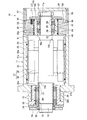
まず、図1を参照して、本発明に係る第1実施形態の主軸装置の全体構成について説明する。
主軸装置10は、ハウジング11と、一端(図中左側)に不図示の工具が取り付けられ、ハウジング11に対して相対回転自在な回転軸12と、回転軸12の前端側(図中左側)に配設された一対の固定側軸受(本実施形態では、アンギュラ玉軸受)13,13と、回転軸12の後端側(図中右側)に配設された一対の自由側軸受(本実施形態では、アンギュラ玉軸受)14,14と、ハウジング11に内挿されて軸方向にスライド移動可能なスリーブ15と、を備える。
(First embodiment)
First, with reference to FIG. 1, the overall configuration of the spindle device of the first embodiment according to the present invention will be described.
The
ハウジング11は、略円筒形状のハウジング本体31と、ハウジング本体31の前端側に嵌合固定されるフロントハウジング32と、ハウジング本体31の後端側に嵌合固定されるリアハウジング33とを有している。フロントハウジング32の前端には、前蓋34が締結固定され、リアハウジング33の後端には、後蓋36が締結固定されている。
The housing 11 includes a substantially
ハウジング本体31の内周面31aに内嵌するスリーブ29には、ビルトインモータ37のステータ38が固定されている。また、回転軸12の軸方向中間部には、ステータ38と対向してロータ39が固定されており、ステータ38が発生する回転磁界によって回転力が与えられて回転軸12を回転駆動する。スリーブ29の外周面には、円環状の複数の溝29aが形成されており、ハウジング本体31に内嵌することで内周面31aとの間に冷却路28が形成される。
A
固定側軸受13,13は、外輪18,18がフロントハウジング32に内嵌され、内輪19,19が回転軸12に外嵌して、回転軸12の前端側を回転自在に支承する。固定側軸受13,13の外輪18,18は、外輪間座20を介してフロントハウジング32の段部32aと前蓋34とによって狭持されてフロントハウジング32に対して軸方向に位置決めされる。内輪19,19は、内輪間座21を介して回転軸12の前側段部12aと、回転軸12に螺合するナット22とによって狭持されて回転軸12に対して軸方向に位置決めされる。フロントハウジング32の外周面には、円環状の複数の溝32bが形成されており、ハウジング本体31に内嵌することでハウジング本体31の内周面31bとの間に冷却路30が形成される。
The fixed
リアハウジング33の内周面33aには、軸方向に移動可能な略円筒形状の軸受スリーブ16が嵌合している。また、軸受スリーブ16の反工具側端面には、軸受スリーブ16の外周面から径方向外方に延出する外輪押え17が不図示のネジによって取り付けられている。なお、軸受スリーブ16と外輪押え17は、本発明のスリーブ15を構成している。
A substantially
リアハウジング33には、その反工具側端面(図中右側面)に開口する複数のばね室55が形成されており、軸受スリーブ16から径方向外方に延出する外輪押え17のフランジ部分の工具側端面と対向する。コイルスプリング56は、ばね室55に収容されて外輪押え17のフランジ部分とばね室55との間に介装される。コイルスプリング56は、スリーブ15に軸方向(図中右方向)の弾性力を付与し、これにより固定側軸受13,13及び自由側軸受14,14に定圧予圧を付与している。
The
自由側軸受14,14は、外輪23,23が軸受スリーブ16に内嵌され、内輪24,24が回転軸12に外嵌して、回転軸12の後端側を回転自在に支承する。自由側軸受14,14の外輪23,23は、外輪間座25を介して軸受スリーブ16の段部16aと外輪押え17の円環状凸部17aとによって狭持されて軸受スリーブ16に対して軸方向に位置決めされる。内輪24,24は、内輪間座26を介して回転軸12の後側段部12bと、回転軸12に螺合するナット27とによって狭持されて回転軸12に対して軸方向に位置決めされる。
The free-
図2及び図3に示すように、軸受スリーブ16の外周面16bには、複数の環状溝41が軸方向に並んで形成されている。隣接する環状溝41間には、スリット42が軸方向に沿って形成されて隣接する環状溝41同士を連通している。スリット42の位相は、180°異なる位相で交互に配置することが望ましい。環状溝41及びスリット42は、軸受スリーブ16をリアハウジング33の内周面33aに嵌合することで、互いに対向する軸受スリーブ16の外周面とリアハウジング33の内周面33aとの間に冷却路40が形成される。この冷却路40には、冷却油等の冷却媒体が流動する。スリット42の位相を180°ずつ異ならせることで、環状溝41内での冷却媒体の澱みが少なくなり、冷却媒体の流れが均一になる。なお、スリット42の位相は、180°に限定されず、冷却媒体がスムーズに流れる任意の位相で設けることができる。
As shown in FIGS. 2 and 3, a plurality of
また、冷却路40の冷却媒体を供給する供給路57の供給口51は、最もビルトインモータ37側に位置する環状溝41に向けて開口するように形成され、冷却媒体を排出する排出路58の排出口52は、ビルトインモータ37から最も離間する環状溝41に向けて開口し、供給口51と180°異なる位相で設けられる。そして、不図示のポンプから圧送される冷却媒体は、供給口51から供給されて冷却路40内を流動して冷却した後、排出口52から排出される。冷却媒体をビルトインモータ37に近い環状溝41から供給することにより、発生熱量の大きな、即ち、温度が高くなり易い部分を、より低温の冷却媒体で冷却することができ、効率的な冷却が可能となる。また、供給口51と排出口52とを180°位相に配置することで、冷却路40がシンメトリック配置となり、均一に冷却することができる。なお、供給口51と排出口52との位相差は、周辺部品の配置に応じて任意に変更することができ、例えば、同位相であってもよい。
また、本実施形態では、供給口51と排出口52は、スリット42の位相と90°異なる位相に設けているが、スリット42との位相差も任意に変更することができ、スリット42の位相と同位相であってもよい。
The
In the present embodiment, the
また、軸受スリーブ16の外周面16bには、冷却路40より軸方向外側に一対の環状凹溝44が形成されている。環状凹溝44には、弾性部材であるOリング45が装着されて、リアハウジング33の内周面33aと軸受スリーブ16との嵌合部を封止している。Oリング45のつぶし代は0.1mm〜2.0mmの範囲にすることが好ましく、軸受スリーブ16の摺動不具合をより解消しやすくするには、0.2mm〜0.5mmの範囲にすることが望ましい。また、軸受スリーブ16とリアハウジング33との嵌め合い隙間は、直径寸法の差、即ち、リアハウジング33の内径−軸受スリーブ16の外径で示される寸法を、5μm〜100μmの範囲にすることが好ましく、隙間不足や軸受スリーブ16の傾きにより摺動不具合を解消しやすくするには、15μm〜50μmの範囲にすることが望ましい。
A pair of
Oリング45の材料としては、一般的なニトリルゴムやアクリルゴムなどに加え、モータビルトインスピンドルの発熱に対応した耐熱性のあるシリコンゴムや各種エラストマー、或いは、冷却媒体に対応した耐膨潤性・耐油性のあるフッ素ゴムなどが、必要に応じて選定される。なお、本実施形態における軸受スリーブ16とリアハウジング33とのスライド量は、加工荷重による変形やスピンドルの熱的な軸方向の膨張を逃げる程度の変位であるので、せいぜい±0.5mm以下、多くとも±1mm以下である。従って、可動シリンダ部に装着されるピストンリングに見られるような大きく、且つ、早いストロークによる摺動摩耗によるシール性低下の問題は小さく、経年変化(熱や初期のしめしろ嵌合)による耐クリープ特性に優れた材料を選定するのが望ましい。
As materials for the O-
図1に示すように、主軸装置10が、固定側軸受13,13を冷却する冷却路30、ビルトインモータ37のステータ38を冷却する冷却路28、及び自由側軸受14,14を冷却する冷却路40の複数の冷却路を備える場合、自由側軸受14,14の最適な冷却としては、冷却装置(図示せず)も他の冷却路28,30とは別系統で設け、冷却路40用に独立させて配設することが好ましい。これにより、冷却媒体の温度調整が、他の冷却路28,30の状況に影響されることなく行うことができる。
As shown in FIG. 1, the
しかし、実用上困難な場合には、冷却装置は独立させず、冷却路40を独立させるだけでもよい。この場合、冷却路40への供給側配管のどこかに絞りを設け、冷却媒体の供給量を制御することで、最適な冷却条件を調整することができる。
However, if it is practically difficult, the cooling device may not be made independent but only the cooling
なお、1経路冷却構成とした場合には、先に発熱量が大きい傾向があるステータ38を冷却する冷却路28に冷却媒体を通過させた後、自由側軸受14,14を冷却する冷却路40に循環させるような経路構成とすれば、主軸装置10全体の温度をより効率的に下げられる。また、自由側軸受14,14の温度をより効率的に冷却したい場合には、上記と逆の経路構成として、より低温の冷却媒体を冷却路40に先に循環させればよく、必要に応じて選択することができる。
In the case of the one-path cooling configuration, after passing the cooling medium through the cooling
以上説明したように、本実施形態の主軸装置10によれば、軸受スリーブ16の外周面16bとリアハウジング33の内周面33aとの間には、冷却媒体が流動可能な冷却路40が形成され、冷却路40は、軸受スリーブ16の外周面16bに形成され、軸方向にそれぞれ並ぶ複数の環状溝41と、隣接する環状溝41間に少なくとも1ヶ所形成されて、隣接する環状溝41同士を連通させるスリット42と、を備えるようにしたため、自由側軸受14,14が内嵌する軸受スリーブ16を直接冷却可能となり、自由側軸受14,14を効率的に冷却できる。これにより、自由側軸受14,14の内部温度が下がり、回転中の転がり接触部や保持器案内面などでの粘度低下による潤滑油膜切れが生じ難く、潤滑不良による寿命低下や自由側軸受14,14の焼付きが防止される。
As described above, according to the
また、リアハウジング33と軸受スリーブ16との両部材を同時に冷却するので、両部材の半径方向収縮量が均一となり、スライド部の隙間(リアハウジング33と軸受スリーブ16との隙間)が詰まらず、隙間不足によるスライド不具合の発生を防止することができる。更に、環状溝41内における冷却媒体の流れがスムーズとなり、軸受スリーブ16全体を均一に冷却することで、冷却による変形歪が生じない。その結果、内嵌する自由側軸受14,14の歪も発生せず、回転軸12の回転精度が高い精度で維持され、主軸装置10の加工精度が良好となる。
Further, since both the members of the
また、スライド部は、常時冷却油が循環しているので、摩擦係数も小さく、よりスライド性が向上される効果もある。スライド部に、ボールガイド(ボールブッシュ)等を配置させ、転がり作用によってスライド性を良くする方法もあるが、剛性低下により、振動の発生や、スピンドルの固有振動数の低下などの不具合が生じる。一方、剛性を上げるために、予圧すきま(即ち、ハウジング内径、ボール、スリーブ外径間のラジアルすきま)を大きくすると、かえって逆に、滑りによるスライドよりもスライド性が悪くなるという問題が生じる。 In addition, since the cooling oil constantly circulates in the slide portion, the friction coefficient is small, and there is an effect that the slide performance is further improved. There is a method in which a ball guide (ball bush) or the like is arranged on the slide portion to improve the slidability by rolling action, but problems such as generation of vibration and reduction of the natural frequency of the spindle occur due to the reduction in rigidity. On the other hand, if the preload clearance (that is, the radial clearance between the inner diameter of the housing, the ball, and the outer diameter of the sleeve) is increased in order to increase the rigidity, on the contrary, there arises a problem that the slidability becomes worse than the sliding by sliding.
また、重切削加工中などに発生することがあるびびり振動などにより、リアハウジング33と軸受スリーブ16間に初期のフレッチング摩耗粉が発生した場合でも、冷却媒体が微摩耗粉を外部に運び去ってくれるので、摩耗粉が助剤となって更にフレッチングが進行してしまうのを抑制することができる。
Even when initial fretting wear powder is generated between the
また、冷却媒体を供給する供給口51は、軸方向一端側に位置する環状溝41に向けて開口し、冷却媒体を排出する排出口52は、軸方向他端側に位置する環状溝41に向けて開口するため、環状溝41内における冷却媒体の流れがスムーズとなり、軸受スリーブ16全体を均一に冷却することができる。これにより、高い回転精度が維持される。
Further, the
更に、冷却路40の軸方向両側には、軸受スリーブ16の外周面16bとリアハウジング33の内周面33aとの間を液密に封止するOリング45が配設されるため、冷却媒体のリークが防止されると共に、Oリング45の弾性により主軸装置10における減衰特性が向上して、特に難削材の加工特性に影響を与える動剛性向上にも寄与する。また、スライド部を流れる冷却媒体のダンパー効果による減衰作用も加わる。
Further, on both sides of the cooling
なお、上記実施形態においては、環状溝41は、図4に示すように、底面41aと側壁面41bとによって矩形の断面形状に形成されている。この矩形断面形状の環状溝41の溝幅B及び深さTの大きさは、適宜選択可能である。
B>Tとすると、環状溝41の半径方向深さが浅いので、軸受スリーブ16の径方向厚みが確保されるので、スリーブ剛性を大きくすることができる。このような形状は、スリーブの加工精度向上を重視する場合や、主軸の剛性を向上する場合などに適用される。また、B<Tとすると、環状溝41の半径方向深さが深いので、環状溝41が軸受に近くに形成され、軸受近傍をより効果的に冷却することができ、冷却効率を向上することができる。このような形状は、主軸の冷却特性向上を重視する場合に適用される。B=Tとすると、上記の効果をバランスよく両立させることができる。
In the above embodiment, the
When B> T, since the radial depth of the
また、環状溝41の断面形状は、矩形以外にも図5に示すような各種形状が可能である。例えば、図5(a)及び図5(b)に示すように、環状溝41の側壁面41bは、軸方向と直交する方向、即ち、半径方向に対して傾斜して形成されてもよい。
Further, the cross-sectional shape of the
具体的に、図5(a)に示す軸受スリーブ16の環状溝41は、溝幅Bが軸受スリーブ16の外周面16bに向かって次第に大きくなる台形溝となっている。即ち、台形状の環状溝41では、環状溝41の断面形状は、底面41aと側壁面41bのなす角度が鈍角(θ1)であるので、リアハウジング33の内周面33aとの干渉がなく、スライド性が向上する。また、図5(b)に示す軸受スリーブ16の環状溝41は、溝幅Bが軸受スリーブ16の外周面16bに向かって次第に小さくなる、所謂、アリ溝となっている。即ち、アリ溝の環状溝41では、環状溝41の断面形状は、底面41aと側壁面41bのなす角度が鋭角(θ2)であるので、発熱源である自由側軸受14,14に近い部分の表面積が大きく、自由側軸受14,14の熱を効率的に冷却媒体に伝達することができ、冷却性能が向上する。
Specifically, the
また、図5(c)に示す軸受スリーブ16の環状溝41は、曲率半径Rの断面半円形であるので、丸形状のバイトで加工することができ、加工する際にバイトの摩滅が少なく、加工性を向上することができる。
Further, the
また、軸受スリーブ16の外周面16bの両端縁部には、図6に示すように、面取り部43が形成されてもよい。面取り部43の外周面16bに対する角度θ3は、3〜45°、より好ましくは、3〜30°とするのがよい。これにより、軸受スリーブ16がリアハウジング33内で傾いても、リアハウジング33の内周面33aとの干渉が防止され、スライド性が確保される。
Further, as shown in FIG. 6, chamfered
また、図7に示すように、軸受スリーブ16の両端縁部の面取り部43に加えて、環状溝41の肩部に面取り部46を形成すれば、リアハウジング33の内周面33aとの干渉が更に防止されて、スライド性が維持される。環状溝41の肩部の面取り角度θ4は、3〜45°、より好ましくは、3〜30°である。
Further, as shown in FIG. 7, if the chamfered
(第2実施形態)
次に、図8及び図9を参照して、本発明に係る主軸装置の第2実施形態について説明する。なお、本実施形態の主軸装置は、環状溝がリアハウジングの内周面に設けられている以外は、第1実施形態と同様であるので、第1実施形態と同一又は同等部分については、図面に同一符号を付してその説明を省略或いは簡略化する。また、自由側軸受近傍のみを図示して説明する。
(Second Embodiment)
Next, a second embodiment of the spindle device according to the present invention will be described with reference to FIGS. The spindle device of this embodiment is the same as that of the first embodiment except that an annular groove is provided on the inner peripheral surface of the rear housing. The same reference numerals are given to the descriptions, and the description thereof is omitted or simplified. Further, only the vicinity of the free-side bearing will be illustrated and described.
図8及び図9に示すように、リアハウジング33の内周面33aには、複数の環状溝47が軸方向に並んで形成されている。隣接する環状溝47間には、スリット48が軸方向に形成されて隣接する環状溝47同士を連通している。スリット48の位相は、180°異なる位相で交互に配置することが望ましい。環状溝47及びスリット48は、軸受スリーブ16をリアハウジング33の内周面33aに嵌合することで、軸受スリーブ16の外周面16bとの間に冷却媒体が流動する冷却路49を形成する。
なお、供給口51と排出口52は、いずれかのスリット42と同位相となるように設けているが、本実施形態においても、スリット42との位相差を任意に設定することができる。
As shown in FIGS. 8 and 9, a plurality of
The
また、リアハウジング33の内周面33aには、冷却路49より軸方向外側に一対の環状凹溝50が形成されている。環状凹溝50には、弾性部材であるOリング45が装着されて、リアハウジング33の内周面33aと軸受スリーブ16との嵌合部を封止している。
A pair of
従って、本実施形態の主軸装置10においても、軸受スリーブ16の外周面16bとリアハウジング33の内周面33aとの間には、冷却媒体が流動可能な冷却路49が形成される。冷却路49は、リアハウジング33の内周面33aに形成され、軸方向にそれぞれ並ぶ複数の環状溝47と、隣接する環状溝47間に少なくとも1ヶ所形成されて、隣接する環状溝47同士を連通させるスリット48と、を備えるようにした。このため、上記第1実施形態と同様の効果を奏することができる。
その他の構成及び作用効果についても、上記第1実施形態と同様である。
Therefore, also in the
Other configurations and operational effects are the same as those in the first embodiment.
なお、本実施形態においても、環状溝47の断面形状や、リアハウジング33の内周面33aの両端縁部の形状は、第1実施形態の環状溝41の断面形状や、軸受スリーブ16の外周面16bの両端縁部の形状と同様に適用することができる。
Also in this embodiment, the cross-sectional shape of the
即ち、リアハウジング33の内周面33aの両端縁部には、面取り部が形成されてもよく、また、複数の環状溝47の側壁面は、軸方向と直交する方向に対して傾斜して形成されてもよい。
That is, chamfered portions may be formed at both end edges of the inner
尚、本発明は、前述した各実施形態に限定されるものではなく、適宜、変形、改良、等が可能である。
例えば、上記実施形態では、固定側軸受と自由側軸受間に定圧予圧により予圧が付与された主軸装置について説明したが、これに限定されず、固定側軸受と自由側軸受にそれぞれ定位置予圧された主軸装置にも適用することができ、同様の効果が得られる。このため、自由側軸受としては、アンギュラ玉軸受に限定されず、円筒ころ軸受など他の転がり軸受が適用されてもよい。
In addition, this invention is not limited to each embodiment mentioned above, A deformation | transformation, improvement, etc. are possible suitably.
For example, in the above-described embodiment, the spindle device in which the preload is applied by the constant pressure preload between the fixed side bearing and the free side bearing has been described. The present invention can also be applied to the main spindle device, and the same effect can be obtained. For this reason, as a free side bearing, it is not limited to an angular ball bearing, Other rolling bearings, such as a cylindrical roller bearing, may be applied.
10 主軸装置
11 ハウジング
12 回転軸
13 固定側軸受
14 自由側軸受
16 軸受スリーブ(スリーブ)
16b スリーブの外周面
18,23 外輪
19,24 内輪
28,30,40,49 冷却路
31 ハウジング本体
32 フロントハウジング
33 リアハウジング(ハウジング)
33a ハウジングの内周面
41,47 環状溝
42 スリット
43 面取り部
45 Oリング(弾性部材)
51 供給口
52 排出口
DESCRIPTION OF
16b Outer peripheral surface of
33a Inner
51
Claims (5)
該ハウジングに対して相対回転自在な回転軸と、
内輪が前記回転軸の一端側に外嵌され、外輪が前記ハウジングに固定される固定側軸受と、
前記回転軸の他端側で前記ハウジング内に配置され、前記回転軸の軸方向に移動可能なスリーブと、
内輪が前記回転軸の他端側に外嵌され、外輪が前記スリーブに内嵌される自由側軸受と、
を有する主軸装置であって、
互いに対向する前記スリーブの外周面と前記ハウジングの内周面との間には、冷却媒体が流動可能な冷却路が形成され、
前記冷却路は、前記スリーブの外周面又は前記ハウジングの内周面に形成され、軸方向にそれぞれ並ぶ複数の環状溝と、隣接する前記環状溝間に少なくとも1ヶ所形成されて、隣接する前記環状溝同士を連通させるスリットと、を備えることを特徴とする主軸装置。 A housing;
A rotating shaft relatively rotatable with respect to the housing;
A fixed-side bearing in which an inner ring is fitted on one end side of the rotating shaft and an outer ring is fixed to the housing;
A sleeve disposed in the housing on the other end side of the rotating shaft and movable in the axial direction of the rotating shaft;
A free side bearing in which an inner ring is fitted on the other end side of the rotary shaft, and an outer ring is fitted in the sleeve;
A spindle device having
A cooling path through which a cooling medium can flow is formed between the outer peripheral surface of the sleeve and the inner peripheral surface of the housing facing each other.
The cooling path is formed on the outer peripheral surface of the sleeve or the inner peripheral surface of the housing, and is formed at least one place between the plurality of annular grooves arranged in the axial direction and the adjacent annular grooves. A spindle device comprising: a slit that allows the grooves to communicate with each other.
Priority Applications (6)
| Application Number | Priority Date | Filing Date | Title |
|---|---|---|---|
| JP2014173221A JP6492459B2 (en) | 2014-02-28 | 2014-08-27 | Spindle device |
| EP15754847.0A EP3112714B1 (en) | 2014-02-28 | 2015-02-26 | Spindle device |
| TW104106376A TWI566879B (en) | 2014-02-28 | 2015-02-26 | Spindle device |
| PCT/JP2015/055696 WO2015129823A1 (en) | 2014-02-28 | 2015-02-26 | Spindle device |
| KR1020167023608A KR101917015B1 (en) | 2014-02-28 | 2015-02-26 | Spindle device |
| CN201580011204.8A CN106062395B (en) | 2014-02-28 | 2015-02-26 | Main shaft device |
Applications Claiming Priority (3)
| Application Number | Priority Date | Filing Date | Title |
|---|---|---|---|
| JP2014039261 | 2014-02-28 | ||
| JP2014039261 | 2014-02-28 | ||
| JP2014173221A JP6492459B2 (en) | 2014-02-28 | 2014-08-27 | Spindle device |
Publications (3)
| Publication Number | Publication Date |
|---|---|
| JP2015178165A JP2015178165A (en) | 2015-10-08 |
| JP2015178165A5 JP2015178165A5 (en) | 2017-10-05 |
| JP6492459B2 true JP6492459B2 (en) | 2019-04-10 |
Family
ID=54009137
Family Applications (1)
| Application Number | Title | Priority Date | Filing Date |
|---|---|---|---|
| JP2014173221A Active JP6492459B2 (en) | 2014-02-28 | 2014-08-27 | Spindle device |
Country Status (6)
| Country | Link |
|---|---|
| EP (1) | EP3112714B1 (en) |
| JP (1) | JP6492459B2 (en) |
| KR (1) | KR101917015B1 (en) |
| CN (1) | CN106062395B (en) |
| TW (1) | TWI566879B (en) |
| WO (1) | WO2015129823A1 (en) |
Families Citing this family (15)
| Publication number | Priority date | Publication date | Assignee | Title |
|---|---|---|---|---|
| WO2018162310A1 (en) | 2017-03-07 | 2018-09-13 | Philips Lighting Holding B.V. | A collimator and a lighting unit |
| CN108574365A (en) * | 2017-03-10 | 2018-09-25 | 郑州宇通客车股份有限公司 | A kind of fluid-cooled electrical machine shell and the fluid-cooled electrical machine using the fluid-cooled electrical machine shell |
| CN108173381B (en) * | 2018-02-05 | 2024-02-13 | 宁夏巨能机器人股份有限公司 | Direct-drive motor for casting sand core carrying truss manipulator |
| FR3085407B1 (en) * | 2018-09-06 | 2020-07-31 | Hevatech | COLD-WORKING PIVOTER DEVICE SUPPORTING A HOT-WORKING TURBINE, ALLOWING TO REDUCE THE COST OF A CONVERTER OF THERMAL ENERGY INTO MECHANICAL AND / OR ELECTRICAL ENERGY |
| US10935120B2 (en) * | 2018-11-30 | 2021-03-02 | Arvinmeritor Technology, Llc | Axle assembly having a spigot bearing assembly |
| CN110695759A (en) * | 2019-09-05 | 2020-01-17 | 深圳市爱贝科精密机械有限公司 | Main shaft cooling device with annular spraying function |
| CN112059212A (en) * | 2020-08-06 | 2020-12-11 | 珠海格力电器股份有限公司 | Spindle front end structure and electric spindle |
| EP3967894B1 (en) * | 2020-09-10 | 2023-11-15 | Fulvio Marsetti | Electrospindle with preloaded bearings for a machine tool |
| CN114483802A (en) * | 2020-10-27 | 2022-05-13 | 斯凯孚公司 | Bearing seat and application thereof |
| CN112780686B (en) * | 2021-01-22 | 2022-06-28 | 苏州汇川技术有限公司 | Bearing cooling structure and driving motor |
| DE102021123523A1 (en) | 2021-06-25 | 2022-12-29 | GEDEE WEILER Pvt Ltd. | Bearing cooling device, single bearing and lathe assembly |
| CN113726080B (en) * | 2021-08-20 | 2023-05-16 | 珠海格力电器股份有限公司 | Bearing vibration damper and motor |
| CN113649603B (en) * | 2021-08-27 | 2022-08-05 | 珠海格力电器股份有限公司 | Electric spindle |
| CN113890261B (en) * | 2021-10-27 | 2022-12-23 | 苏州汇川控制技术有限公司 | Direct-drive mechanism and processing equipment |
| CN115342118B (en) * | 2022-08-16 | 2023-12-15 | 杭州鑫凯传动机械有限公司 | Automatic circulation liquid-cooled universal joint cross shaft |
Family Cites Families (19)
| Publication number | Priority date | Publication date | Assignee | Title |
|---|---|---|---|---|
| JPS6152725U (en) * | 1984-09-13 | 1986-04-09 | ||
| JPH0620642B2 (en) * | 1984-11-15 | 1994-03-23 | 光洋精工株式会社 | Rolling bearing device for machine tool spindle |
| GB8807663D0 (en) * | 1988-03-31 | 1988-05-05 | Aisin Seiki | Dynamoelectric machines |
| JPH04133555A (en) | 1990-09-26 | 1992-05-07 | Nippon Telegr & Teleph Corp <Ntt> | Multi-spot simultaneous broadcast system |
| JPH1058277A (en) * | 1996-08-26 | 1998-03-03 | Niigata Eng Co Ltd | Spindle cooling device of machine tool |
| JPH10225802A (en) * | 1997-02-14 | 1998-08-25 | Okuma Mach Works Ltd | Main spindle device for machine tool |
| SE510204C2 (en) * | 1997-06-16 | 1999-05-03 | Alfa Laval Ab | Apparatus and means for cooling a bearing |
| JP2000158288A (en) * | 1998-11-27 | 2000-06-13 | Koyo Mach Ind Co Ltd | Main spindle cooling device for machine tool and spindle device |
| JP3613754B2 (en) * | 1999-04-30 | 2005-01-26 | 株式会社ニイガタマシンテクノ | Machine tool spindle equipment |
| CN2464981Y (en) * | 2001-02-20 | 2001-12-12 | 陈疆 | Roller support for sugar press |
| CN100455407C (en) * | 2002-07-29 | 2009-01-28 | 日本精工株式会社 | Rolling bearing, grease replenishing device, main shaft device, grease replenishing method, and grease replenishing program |
| JP4865371B2 (en) * | 2006-03-15 | 2012-02-01 | ブラザー工業株式会社 | Spindle cooling device for machine tools |
| TWI324429B (en) * | 2006-12-14 | 2010-05-01 | Alan Xiao | Method of cooling system for use in motor or spindle |
| JP5146269B2 (en) * | 2007-11-07 | 2013-02-20 | 日本精工株式会社 | Ball bearing |
| JP5464879B2 (en) * | 2009-03-24 | 2014-04-09 | 高松機械工業株式会社 | Machine Tools |
| KR101050063B1 (en) * | 2009-04-07 | 2011-07-19 | (주) 카스윈 | Chiller of cartridge type spindle unit |
| JP5687453B2 (en) * | 2010-08-11 | 2015-03-18 | Ntn株式会社 | Hydrostatic gas bearing spindle |
| CN202326756U (en) * | 2011-11-26 | 2012-07-11 | 广州市昊志机电股份有限公司 | Upper bearing base sleeve structure for rolling ball high-speed spindle |
| DE102012008209A1 (en) * | 2012-04-21 | 2013-10-24 | Volkswagen Aktiengesellschaft | Electric machine |
-
2014
- 2014-08-27 JP JP2014173221A patent/JP6492459B2/en active Active
-
2015
- 2015-02-26 WO PCT/JP2015/055696 patent/WO2015129823A1/en active Application Filing
- 2015-02-26 KR KR1020167023608A patent/KR101917015B1/en active IP Right Grant
- 2015-02-26 EP EP15754847.0A patent/EP3112714B1/en active Active
- 2015-02-26 TW TW104106376A patent/TWI566879B/en not_active IP Right Cessation
- 2015-02-26 CN CN201580011204.8A patent/CN106062395B/en active Active
Also Published As
| Publication number | Publication date |
|---|---|
| KR101917015B1 (en) | 2018-11-08 |
| CN106062395A (en) | 2016-10-26 |
| WO2015129823A1 (en) | 2015-09-03 |
| CN106062395B (en) | 2019-03-29 |
| EP3112714A4 (en) | 2017-03-22 |
| TWI566879B (en) | 2017-01-21 |
| EP3112714A1 (en) | 2017-01-04 |
| TW201544232A (en) | 2015-12-01 |
| EP3112714B1 (en) | 2018-05-02 |
| JP2015178165A (en) | 2015-10-08 |
| KR20160113275A (en) | 2016-09-28 |
Similar Documents
| Publication | Publication Date | Title |
|---|---|---|
| JP6492459B2 (en) | Spindle device | |
| JP6484960B2 (en) | Spindle device | |
| KR101917016B1 (en) | Main shaft device | |
| JP6507393B2 (en) | Slide bearing and pump | |
| JP6451146B2 (en) | Spindle device | |
| JP6451147B2 (en) | Spindle device | |
| KR102556910B1 (en) | Vented bearing retainer for turbomachinery | |
| JP7210566B2 (en) | Seal ring | |
| JP2007024256A (en) | Lubricating device of rolling bearing | |
| WO2015129826A1 (en) | Main shaft device | |
| JP6704107B2 (en) | Thrust collar and thrust bearing device | |
| JP2007024258A (en) | Lubricating device of rolling bearing | |
| JP7067637B2 (en) | Motor built-in spindle device | |
| JP4527622B2 (en) | Rolling bearing lubrication system | |
| KR101727813B1 (en) | Hydrostatic bearing and machine tool having the same | |
| US20210095766A1 (en) | A sealing arrangement for a hydrodynamic machine for a vehicle |
Legal Events
| Date | Code | Title | Description |
|---|---|---|---|
| A521 | Request for written amendment filed |
Free format text: JAPANESE INTERMEDIATE CODE: A523 Effective date: 20170824 |
|
| A621 | Written request for application examination |
Free format text: JAPANESE INTERMEDIATE CODE: A621 Effective date: 20170824 |
|
| A131 | Notification of reasons for refusal |
Free format text: JAPANESE INTERMEDIATE CODE: A131 Effective date: 20180612 |
|
| TRDD | Decision of grant or rejection written | ||
| A01 | Written decision to grant a patent or to grant a registration (utility model) |
Free format text: JAPANESE INTERMEDIATE CODE: A01 Effective date: 20190205 |
|
| A61 | First payment of annual fees (during grant procedure) |
Free format text: JAPANESE INTERMEDIATE CODE: A61 Effective date: 20190218 |
|
| R150 | Certificate of patent or registration of utility model |
Ref document number: 6492459 Country of ref document: JP Free format text: JAPANESE INTERMEDIATE CODE: R150 |