JP4862002B2 - Thin substrate rotation processing equipment - Google Patents
Thin substrate rotation processing equipment Download PDFInfo
- Publication number
- JP4862002B2 JP4862002B2 JP2008046844A JP2008046844A JP4862002B2 JP 4862002 B2 JP4862002 B2 JP 4862002B2 JP 2008046844 A JP2008046844 A JP 2008046844A JP 2008046844 A JP2008046844 A JP 2008046844A JP 4862002 B2 JP4862002 B2 JP 4862002B2
- Authority
- JP
- Japan
- Prior art keywords
- stator
- rotor
- support member
- rotating
- rotating body
- Prior art date
- Legal status (The legal status is an assumption and is not a legal conclusion. Google has not performed a legal analysis and makes no representation as to the accuracy of the status listed.)
- Expired - Fee Related
Links
- 239000000758 substrate Substances 0.000 title claims description 61
- 239000007788 liquid Substances 0.000 claims description 29
- 230000002093 peripheral effect Effects 0.000 claims description 28
- 238000004519 manufacturing process Methods 0.000 description 12
- 239000010409 thin film Substances 0.000 description 9
- 235000012489 doughnuts Nutrition 0.000 description 8
- 238000000034 method Methods 0.000 description 8
- 239000004065 semiconductor Substances 0.000 description 8
- 230000007246 mechanism Effects 0.000 description 7
- 230000008569 process Effects 0.000 description 6
- 230000005484 gravity Effects 0.000 description 5
- 230000005540 biological transmission Effects 0.000 description 3
- 230000002265 prevention Effects 0.000 description 3
- 210000000078 claw Anatomy 0.000 description 2
- 238000004140 cleaning Methods 0.000 description 2
- 230000003749 cleanliness Effects 0.000 description 2
- 230000002950 deficient Effects 0.000 description 2
- 238000001035 drying Methods 0.000 description 2
- 239000000428 dust Substances 0.000 description 2
- 230000005611 electricity Effects 0.000 description 2
- 239000010408 film Substances 0.000 description 2
- 239000004973 liquid crystal related substance Substances 0.000 description 2
- 239000003595 mist Substances 0.000 description 2
- 229920002120 photoresistant polymer Polymers 0.000 description 2
- 239000007921 spray Substances 0.000 description 2
- 238000004381 surface treatment Methods 0.000 description 2
- 241000255777 Lepidoptera Species 0.000 description 1
- 230000015572 biosynthetic process Effects 0.000 description 1
- 238000011109 contamination Methods 0.000 description 1
- 238000010586 diagram Methods 0.000 description 1
- 239000011521 glass Substances 0.000 description 1
- 230000006872 improvement Effects 0.000 description 1
- 239000012535 impurity Substances 0.000 description 1
- 238000011084 recovery Methods 0.000 description 1
- 238000004904 shortening Methods 0.000 description 1
- 230000007704 transition Effects 0.000 description 1
Images


Landscapes
- Container, Conveyance, Adherence, Positioning, Of Wafer (AREA)
- Exposure Of Semiconductors, Excluding Electron Or Ion Beam Exposure (AREA)
- Cleaning Or Drying Semiconductors (AREA)
- Coating Apparatus (AREA)
Description
本発明は、半導体や液晶等の製造において、薄板状物、特に基板を回転させ、その表面に処理液を滴下、分散させて薄膜を形成し、又は表面を洗浄、乾燥する装置であるいわゆるスピンコータに関するものである。 The present invention relates to a so-called spin coater which is an apparatus for rotating a thin plate, particularly a substrate, forming a thin film by dripping and dispersing a treatment liquid on the surface thereof, or cleaning and drying the surface in the manufacture of semiconductors and liquid crystals. It is about.
半導体や液晶等の製造においては、半導体ウエハやガラス板等の基板の表面にフォトレジストの薄膜を形成し、あるいは表面を洗浄又は乾燥する作業工程があるが、そこでは回転ヘッド部上に載置された基板を拘束で回転させる装置が用いられている。 In the manufacture of semiconductors, liquid crystals, etc., there is an operation process in which a photoresist thin film is formed on the surface of a substrate such as a semiconductor wafer or glass plate, or the surface is washed or dried. A device that rotates the substrate thus obtained by restraint is used.
例えば、薄膜形成工程においては、フォトレジスト等の処理液が滴下された基板を高速回転させることにより、処理液を遠心力で拡げて薄膜を形成する、表面処理装置であるスピンコータが用いられている。ここで、スピンコータは半導体製造工場内のクリーンルーム中で使用される。 For example, in a thin film forming process, a spin coater, which is a surface treatment device, is used to form a thin film by expanding a processing liquid by centrifugal force by rotating a substrate on which a processing liquid such as a photoresist is dropped at high speed. . Here, the spin coater is used in a clean room in a semiconductor manufacturing factory.
図9に従来型スピンコータの構造を示す。 FIG. 9 shows the structure of a conventional spin coater.
従来のスピンコータ1は、水平に置かれた腕状、矩形状若しくは円盤状の基板支持部材23と、その下面中心から下方に伸びるロータ部材22と、そのロータ部材22の下方にドライブベルト34によって接続される駆動モータ33を具備している。基板支持部材23の上面にはウエハ14が載置され、その周囲にはウエハ14に滴下された処理液32の飛散を防止する飛散防止壁13が設けられている。基板支持部材23の上方には処理液32を滴下するための吐出ノズル31が配置されている。
The
以下にスピンコータ1の動作を説明する。まず、前工程から移送されたウエハ14は、基板支持部材23上に真空チャッキング等により載置される。次に駆動モータ33によりロータ部材22を介して基板支持部材23とともにウエハ14を、例えば2000rpmや6000rpm等の高速に回転させる。
The operation of the
そして、回転するウエハ14の表面に上方の吐出ノズル31から処理液32を滴下すると、処理液32は遠心力によりウエハ14の表面に拡がり薄膜を形成する。
When the
なお、この薄膜の形成に寄与しなかった余分の処理液32は、ウエハ14表面より振り飛ばされて、飛散防止壁13に衝突することにより捕集され下部から回収される。
The
このような薄膜形成工程は、通常、薄膜への不純物の混入を避けるため、クリーンルーム内で行われ、特に図9に示したウエハ処理を行うA側は、B側に比べクリーンに維持される。 Such a thin film forming process is usually performed in a clean room in order to avoid contamination of the thin film with impurities. In particular, the A side where the wafer processing shown in FIG. 9 is performed is kept clean compared to the B side.
上述のウエハ製造において、不良品を減らし、歩留を上昇させることが極めて重要であり、そのための発明が以下のようになされている。例えば、処理液32をウエハ14表面へ塗布する際の均一性向上の方法が発明されたり(例えば特許文献1参照)、例えば、ウエハ14は上面だけではなく下面を高い清浄度に維持する必要があり、その要求に応えるために、ウエハ下面に向けて処理液32を噴射する下部処理液用のノズルが配置されたりしている。(例えば特許文献2を参照)。
In the above-mentioned wafer manufacturing, it is extremely important to reduce defective products and increase yield, and the invention for that purpose is made as follows. For example, a method for improving uniformity when the
また、生産効率向上のためウエハの大型化が進んでおり、同時にスピンコータのロータ部材22に多くの機構が組み込まれ、そのため前記ロータ部材22が大型化し、重量も増加していく傾向にある。
前述のようにウエハの生産効率向上と共に、スピンコータのロータ部材に多くの機構が組み込まれ重量が増大し、長大化したため、前記ロータ部材を高速回転させた際の安定性が確保されなくなってきた。 As described above, along with the improvement in wafer production efficiency, many mechanisms have been incorporated into the rotor member of the spin coater, resulting in an increase in weight and an increase in length. Therefore, stability cannot be ensured when the rotor member is rotated at a high speed.
すなわち、鉛直方向に長尺であるスピンコータはロータ部材22の上面と下面の距離が離れているため、上面側若しくは下面側の回転中心がずれた場合、そのずれが微細な量であったとしても、鉛直方向の距離が長いため、ロータ部材22にかかる慣性力は大きくなり、安定性を失い。特にスピンコータは2000rpmから6000rpmの高速である領域で回転させるため、ロータ部材22にかかる慣性力はさらに大きなものとなる。
That is, since the distance between the upper surface and the lower surface of the
加えて、スピンコータは停止状態から高速回転状態に瞬時に加速し、瞬時に停止状態に戻すという運転方法を取るため、ロータ部材22にかかる慣性力はさらに大きなものとなる。
In addition, since the spin coater takes an operation method of instantaneously accelerating from the stopped state to the high speed rotating state and instantaneously returning to the stopped state, the inertial force applied to the
上記のようにロータ部材22の安定性が失われると、ウエハ14の処理が適切に行えなくなり、不良品となってしまい、歩留を著しく下げることとなる。そのため、ウエハ14の生産性向上のためには、ロータ部材22の安定的回転の確保が極めて重要な課題となっている。
If the stability of the
本発明は上述の問題を解決するためになされたものであり、その目的は、多機能化に伴い大型化するスピンコータのロータ部材の、安定的回転を確保し、さらに、スピンコータの鉛直方向における短尺化により、工場内の容積効率向上を実現するものである。 The present invention has been made to solve the above-described problems, and its object is to ensure stable rotation of a rotor member of a spin coater that increases in size as the number of functions increases, and to further reduce the length of the spin coater in the vertical direction. This will improve the volume efficiency in the factory.
上記課題を解決するため、本発明に係る基板を回転処理する装置(スピンコータ1)は、筒状の固定部材45の外周側に、環状に形成されたステータコイル28を固定して構成したステータ部材21と、前記ステータ部材21の内周側に回転可能に、回転体41を支持し、この回転体41の側面であって、前記ステータタコイル28を囲み、接近するように、複数の永久磁石29を配置して、前記回転体41と共に回転するロータ部材22を形成し、前記ステータ部材21と前記ロータ部材22を合わせて偏平状の電動機20(例えばモータ)を形成し、前記回転体41の上面に基板支持部材23を配置し、前記基板支持部材23に支持された薄板状被処理物(ウエハ14)の裏面に処理液32を噴射するようにパイプ35を配設したことを特徴とする。
In order to solve the above problems, an apparatus (spin coater 1) for rotating a substrate according to the present invention includes a stator member formed by fixing an
上記の基板を回転処理する装置において、前記回転体41は内縁筒部42と環状の平板部44と、この平板部の外周に形成された外縁筒部43を有し、前記外縁筒部43の内面
に複数の永久磁石29を配置した前記ロータ部材22の、前記内縁筒部42の外面を前記ステータ部材21へ回転可能に支持させることで構成した偏平状の電動機20を具備したことを特徴とする。
In the apparatus for rotating the substrate described above, the rotating body 41 has an inner edge cylindrical portion 42, an annular flat plate portion 44, and an outer edge cylindrical portion 43 formed on the outer periphery of the flat plate portion. The
上記の基板を回転処理する装置において、筒状の固定部材45の外周に、前記環状のステータコイル28を固定し、さらに前記固定部材45の下端が筐体46に固定された支持部材47に固定されていることを特徴とする。
In the apparatus for rotating the substrate described above, the
上記課題を解決するための本発明に係る基板を回転処理する装置(スピンコータ1)は、筒状の固定部材45の内周側に、環状に形成されたステータコイル28を固定して構成したステータ部材21と、前記ステータ部材21の内周側に回転可能に、回転体41を支持し、この回転体41の側面であって、複数の永久磁石29を、前記円環状に形成されたステータコイル28の内周側に接近するように配置して、前記回転体41と共に回転するロータ部材22を形成し、前記ステータ部材21と前記ロータ部材22を合わせて偏平状の電動機20を形成し、前記回転体41の上面に基板支持部材23を配置し、前記基板支持部材23に支持された薄板状被処理物(ウエハ14)の裏面に処理液32を噴射するようにパイプ35を配設したことを特徴とする。
An apparatus (spin coater 1) for rotating a substrate according to the present invention for solving the above-mentioned problems is a stator in which an
上記の基板を回転処理する装置において、円筒状の回転体41の外周側に、複数の永久磁石29を環状に配置したロータ部材22と、前記永久磁石29の上方及び下方を軸支持体24により軸支持し、永久磁石29上方の軸支持体24より外周方向に伸びる上方環状板36と、永久磁石29下方の軸支持体24より外周方向に伸びる下方環状板37が、円筒状の側壁板38により接続し、前記側壁板38の内周側で、かつ前記永久磁石29を囲み、接近するように環状のステータコイル28を配置したステータ部材21を形成し、前記ステータ部材21と前記ロータ部材22を合わせて形成した偏平状の電動機20を具備したことを特徴とする。
In the apparatus for rotating the substrate described above, the
上記の基板を回転処理する装置において、前記パイプ35に負圧を発生させることで、前記基板支持部材23に前記薄板状被処理物(ウエハ14)が吸着するように構成したことを特徴とする。
In the apparatus for rotating a substrate, the thin plate-like object (wafer 14) is attracted to the
上記の基板を回転処理する装置において、前記ステータ部材21は、筐体46に固定された支持部材47に固定され、前記ステータ部材21と前記ロータ部材22を合わせて偏平状の電動機20を形成し、前記電動機20のロータ部材22の上面に基板支持部材23を配置し、前記基板支持部材23に支持された薄板状被処理物(ウエハ14)の上面に処理液32を噴射するように、1つ又は複数のパイプ35を配設し、前記ウエハ14の裏面に処理液32を噴射するように、1つ又は複数のパイプ35を配設したことを特徴とする。
In the apparatus for rotating the substrate described above, the
薄板状物であるウエハ14を回転させるための駆動力を、偏平状の電動機20にすることで、基盤回転処理装置であるスピンコータ1の高さを低く構成することが可能となり、それによりロータ部材22の重心が、従来に比べ鉛直方向に低い位置となるため、ロータ部材22の安定性が向上した。
By using a flat
さらに、スピンコータ1が従来に比べ鉛直方向に短尺に構成することが可能となり、スピンコータ1の設置される工場内の、クリーンルームにおける容積効率が向上した。
Furthermore, the
中空部26を有する環状の電動機20を用いたことにより、ウエハ14の上面に加えて下面を同時に処理可能となるスピンコータ1を構成することが可能となった。
By using the annular
偏平状かつ環状の電動機20を用いることで、従来の駆動モータ33に必要であったドライブベルト34やドライブギア等の動力伝達機構が不必要となり、ステータ部材21及びロータ部材22を組み合わせて構成した電動機20と、基板支持部材23の回転中心を同軸線上とした状態で直接、連結することが可能となった。
By using the flat and annular
スピンコータ1に動力伝達機構がなくなるため、低振動及び低騒音化が実現した。また、回転部分が鉛直方向に短尺となるため、装置の安定性が増し、それに伴い均一な膜ができるようになり、成膜品質の上昇が実現した。さらに、低振動化が実現することにより、スピンコータ1及び周辺機器から構成されるユニットを複数段重ねることが可能となった。
Since the
偏平状かつ環状の電動機20を使用することにより、ウエハ14の下面処理のための機構や、ウエハ14を基板支持部材23に固定するために、ウエハ14の下方に負圧を発生させる機構を従来通り具備しながら、スピンコータの鉛直方向の短尺化を実現し、同時にロータ部材22の安定的回転を実現した。
A mechanism for processing the lower surface of the
以下、本発明を図に示す実施形態を参照して具体的に説明する。 Hereinafter, the present invention will be specifically described with reference to embodiments shown in the drawings.
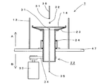
図1は本発明の薄型基板回転処理装置(スピンコータ1)の概略を示している。スピンコータ1は、駆動モータであるアウターロータ型の電動機20に基板支持部材23を固定し、前記電動機20は支持部材47に設置されている。前記基板支持部材23には被処理物である基板(ウエハ14)が載置され、その上方には処理液32を供給するためのパイプ35が配置されており、ウエハ14の外周方向には前記処理液32の飛散を防止するための飛散防止壁13が設置されている。また、ウエハ14の下方には、下面処理用のノズル31を持つパイプ35が配置されている。
FIG. 1 schematically shows a thin substrate rotation processing apparatus (spin coater 1) of the present invention. The
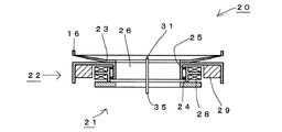
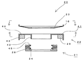
図2はアウターロータ型の電動機20を利用したスピンコータ1の主要部概略、図3はその主要部の分解図を示している。アウターロータ型の電動機20は、ステータ部材21とロータ部材22が軸支持体24を介して結合されており、中空部26を持つドーナツ状となっている。ステータ部材21はドーナツ状であり、側壁外周側にステータコイル28を、内周側には前記ロータ部材22の内縁筒部42と結合するための軸支持体24を有している。
FIG. 2 is a schematic view of the main part of the
また、ロータ部材22は、内縁筒部42と外縁筒部43と、前記内縁筒部42と外縁筒部43をつなぐ環状の平板部44から形成された回転体41に、前記外縁筒部43の内周側に、前記ステータコイル28に対向するように永久磁石29を固定して構成した。前記ステータコイル28に電気を流すことで、固定されたステータ部材21に対して、ロータ部材22が回転する電動機20となる。
In addition, the
図4はインナーロータ型の電動機20を利用した薄型基板回転処理装置(スピンコータ1)の主要部概略、図5はその主要部の分解図を示している。インナーロータ型の電動機20は、ステータ部材21とロータ部材22が軸支持体24を介して結合されており、中空部26を持つドーナツ状となっている。
FIG. 4 is a schematic view of a main part of a thin substrate rotation processing apparatus (spin coater 1) using an inner rotor type
前記ロータ部材22は、円筒状の回転体41外周側に複数個の永久磁石29を環状に固定して構成している。
The
前記ステータ部材21は、前記ロータ部材22に固定された複数個の永久磁石29の、上方、及び下方を軸支持体24により支持し、永久磁石29の上方の軸支持体24より外周方向に伸びる上方環状板36と、永久磁石29の下方の軸支持体24より外周方向に伸びる下方環状板37を、円筒状の側壁板38により接続し、前記側壁板38の内周側で、かつ前記永久磁石29を囲み、接近するように環状のステータコイル28を前記側壁板38に固定して構成している。
The
前記ステータ部材21と前記ロータ部材22を合わせて、偏平状かつドーナツ状の電動機20を構成している。ここで、前記ステータコイル28に電気を流すことで、固定されたステータ部材21に対して、ロータ部材22が回転する。
The
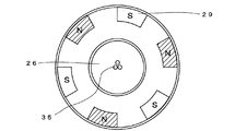
図6は、図3のC−C矢視図である。永久磁石29の配列の1例を示しており、中空部26の中心部にはパイプ35が貫通している様子を示している。
FIG. 6 is a CC arrow view of FIG. An example of the arrangement of the
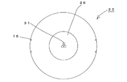
図7は、図3のD−D矢視図である。基板支持部材23はドーナツ状であり、ウエハ14を保持するための爪16を有しており、中空部26の中心部にはパイプ35が貫通している様子を示している。基板支持部材23はドーナツ状に限らず、中心に孔を持つ形状であれば、矩形でも他の形状であっても問題はない。
FIG. 7 is a view taken along the line DD in FIG. The
図8は本発明のスピンコータ1を工場内に、鉛直方向に2台重ねて設置している状態を示している。
FIG. 8 shows a state in which two
図9はウエハ14の下面処理機能を有した、従来型のスピンコータ1の概略図である。
FIG. 9 is a schematic view of a
本発明は図9に示す従来型のスピンコータにおける駆動モータ33を、図1に示すように、偏平状かつ環状の電動機20に変更することにより、スピンコータ1の鉛直方向の高さを低く構成し、かつ回転部分の重心を低く、回転が安定的に行われるよう構成したことを特徴とする。
In the present invention, the vertical motor height of the
本発明のスピンコータ1における偏平状かつ環状の電動機20の具体例として、図2及び図3に示すアウターロータ型の電動機20と、図4及び図5に示すインナーロータ型の電動機20が考えられる。
As specific examples of the flat and annular
アウターロータ型の電動機20は、図2及び図3に示すように、ステータ部材21、ロータ部材22及び基板支持部材23から構成されている。
As shown in FIGS. 2 and 3, the outer rotor type
ステータ部材21はドーナツ状で、固定部材45の内周側にロータ部材22を回転可能に保持するためのベアリング等の軸支持体24を、外周側には電動機を構成するためのステータコイル28を具備している。前述したように、ウエハ14を処理するため、図1のA側は極めてクリーンな状態を維持する必要があるため、軸支持体24はシール付のボールベアリング等の、オイルミストや他のダストの発生が低減されているものを使用するのが望ましい。
The
ロータ部材22はドーナツ状で、外縁筒部43の内周側に電動機20を形成するための永久磁石29を具備している。ロータ部材22の外周方向に比較的質量のある永久磁石29を備えているため、今後見込まれるウエハ14の大型化に対応させることも容易となっている。
The
すなわち、半導体製造の高効率化を実現するためにウエハ14は、近年も直径200mmから300mmへ移行が始まっているように、大型化の一途を辿っており、今後もさらに大型になることが予見される。このウエハ14の大型化に伴い、基板支持部材23の大型化が必要となり、次第にロータ部材22の上部の重量が増加していくと考えられる。
In other words, in order to achieve high efficiency in semiconductor manufacturing, the
その際、アウターロータ型の電動機20を採用した本発明のスピンコータ1であれば、ロータ部材22の重量が永久磁石29の影響で大きくなり、さらにロータ部材22の外周側に重量物である永久磁石29が配置されているため、ロータ部材22が生む慣性モーメントが大きくなっている。そのため、基板支持部材23等の大型化が進んでも、その影響を小さくすることが可能である。
At that time, if the
図6は、図3に示したC−C矢視図であり、アウターロータ型の電動機20のロータ部材22に配置されている永久磁石29の様子を示している。永久磁石29は前記ロータ部材22の外縁筒部の内側に沿うように、N極、S極が交互になるように配置されている。中央の中空部26にはウエハ14の下面処理用パイプ35が中央に配置されており、パイプ35は必要に応じて1本から複数本を自由に設置することが可能である。
FIG. 6 is a CC arrow view shown in FIG. 3 and shows a state of the
図7は、図3に示したD−D矢視図であり、基板支持部材23の上面を示している。中央の中空部26には下面処理用パイプ35につながる吐出ノズル31が配置されている。外周上には、載置されたウエハ14を保持するための爪16が設置されている。
FIG. 7 is a DD arrow view shown in FIG. 3 and shows the upper surface of the
インナーロータ型の電動機20は、図4及び図5に示すように、ステータ部材21、ロータ部材22及び基板支持部材23から構成されている。
As shown in FIGS. 4 and 5, the inner rotor type
ステータ部材21はドーナツ状で、側壁板38に電動機20を形成するためのステータコイル28を、そのさらに内周側に、ロータ部材22を回転可能に支持するための、ベアリング等の軸支持体24を具備している。ここで、軸支持体24は前述のアウターロータ型の電動機20の場合と同様に、オイルミストやダストの発生を低減したシール付ボールベアリング等を使用することが望ましい。
The
ロータ部材22は円筒状の回転体41の外側に、電動機20を構成するための永久磁石29を配置している。永久磁石29は、前述のアウターロータ型の電動機20と同様に、N極とS極が交互に、かつ環状に複数個、配置されている。
In the
前述の偏平状かつ環状の電動機20を採用したことにより、図9に示す従来のスピンコータ1の持つ回転時の重心が不安定であった問題を解消した。すなわち、従来のスピンコータ1は回転動力の伝達部とロータ部材22及び基板支持部材23の鉛直方向の重心のずれが生じているため、瞬時に高速回転に達するスピンコータ1においては、安定性を維持するのが困難である問題を抱えていた。
By adopting the flat and annular
上記の問題に対して、本発明におけるスピンコータ1は図1に示すように、駆動モータ33を、偏平状かつ環状の例えばアウターロータ型の電動機20を採用することで、装置の高さを低く抑え、かつ下面処理用のパイプ35を通すための中空部26を設けることを可能とした。また、高さの低い偏平状の電動機20を採用したことで、ロータ部材22とその上部に固定された基板支持部材23等を含めた回転部分における重心が、鉛直方向に低い位置となるため、回転時の安定性向上を実現した。
As shown in FIG. 1, the
図8は本発明の薄型スピンコータ1を、半導体生産工場内に設置する際のユニットに対応させた概略図を示している。前記スピンコータ1は、飛散防止壁13と前記スピンコータ1を固定するための支持部材47から構成される筐体46に内包されることで、ユニットを構成している。ここに、本発明のスピンコータ1は薄型化を実現したため、図8に示すように1つのユニットに複数のスピンコータ1を設置することを可能とした。
FIG. 8 shows a schematic diagram corresponding to a unit when the
図9に示す従来のスピンコータ1は、高さが約600mmであり、駆動モータ33やパイプ35等の取り合いを含め、高さが約1800mmのユニットとして構築し、工場に載置されている。
The
これに対して、図8に示す本発明の薄型スピンコータ1は、高さを80mmから120mm程度とし、パイプ35等の取り合いを含めても高さが250mmから350mm程度に収めることが可能となった。そのため、工場で使用する際の高さ約1800mmのユニットに2段又はそれ以上重ねて配置することが可能となり、工場内の容積効率が向上し、半導体生産工場の限られたクリーンルームの中に、従来以上の台数のスピンコータ1を設置することが可能となるので、生産効率の飛躍的な向上が実現した。
On the other hand, the
図1に示すように、処理液32を滴下するためのパイプ35は、用途に合わせて複数本配置することが可能であり、例えば処理液32の他に乾燥用エアーを噴くパイプ35を設置する等が可能である。また、下面処理用のパイプ35はウエハ14の下面を洗浄するために使用するが、用途に合わせて複数本配置することが可能であり、例えば、ウエハ14が基板支持部材23に確実に保持されるよう、負圧を発生させる吸引用のパイプ35を設置する等が可能である。
As shown in FIG. 1, a plurality of
ウエハ14は処理液32を滴下された後、高速に回転されることにより、処理液32は遠心力の作用を受け、ウエハ14上に薄く引き延ばされ、薄膜を形成する。その際、余分な処理液32がウエハ14上から吹き飛ばされるため、処理液32の飛散を防止し、また、余分な処理液32を回収する図示しない回収機構を備えた飛散防止壁13を設置している。
After the
従来例と同様に、図1に示すA側は、B側以上に清浄が保たれる環境にある。 As in the conventional example, the A side shown in FIG. 1 is in an environment where the cleanliness is maintained more than the B side.
以上、本発明の薄型基板回転処理装置であるスピンコータ1により、多機能化に伴い大型化するスピンコータの鉛直方向における短尺化を実現し、それにより、ロータ部材22の安定的回転を確保し、かつ工場内の容積率向上を実現することができた。その結果、半導体製造における生産効率の飛躍的向上を実現した。
As described above, the
1 基板回転処理装置(スピンコータ)
14 ウエハ
21 ステータ部材
22 ロータ部材
23 基板支持部材
28 ステータコイル
29 永久磁石
1. Substrate rotation processing equipment (spin coater)
14
Claims (6)
前記ステータ部材の内周側に回転可能に、回転体を支持し、この回転体の側面であって、前記ステータタコイルを囲み、接近するように、複数の永久磁石を配置して、前記回転体と共に回転するロータ部材を形成し、
前記ステータ部材と前記ロータ部材を合わせて偏平状の電動機を形成し、
前記回転体の上面に基板支持部材を配置し、
前記基板支持部材に支持された薄板状被処理物の裏面に処理液を噴射するようにパイプを配設し、
前記回転体は内縁筒部と環状の平板部と、この平板部の外周に形成された外縁筒部を有し、
前記外縁筒部の内面に複数の永久磁石を配置した前記ロータ部材の、
前記内縁筒部の外面を前記ステータ部材へ回転可能に支持させることで構成した偏平状の電動機を具備したこと
を特徴とする基板を回転処理する装置。 A stator member configured by fixing a ring-shaped stator coil on the outer peripheral side of the cylindrical fixing member;
A rotating body is rotatably supported on the inner peripheral side of the stator member, and a plurality of permanent magnets are arranged on the side surface of the rotating body so as to surround and approach the stator coil, and the rotation Forming a rotor member that rotates with the body,
A flat motor is formed by combining the stator member and the rotor member,
A substrate support member is disposed on the upper surface of the rotating body,
A pipe is disposed so as to inject the processing liquid onto the back surface of the thin plate-like object to be processed supported by the substrate support member ,
The rotating body has an inner edge cylinder part, an annular flat plate part, and an outer edge cylinder part formed on the outer periphery of the flat plate part,
Of the rotor member in which a plurality of permanent magnets are arranged on the inner surface of the outer edge cylindrical portion,
An apparatus for rotating a substrate , comprising a flat electric motor configured by rotatably supporting an outer surface of the inner edge cylindrical portion on the stator member .
更に前記固定部材の下端が筐体に固定された支持部材に固定されていること
を特徴とする請求項1に記載の基板を回転処理する装置。 The annular stator coil is fixed to the outer periphery of the cylindrical fixing member,
The apparatus for rotating a substrate according to claim 1 , wherein a lower end of the fixing member is fixed to a support member fixed to the housing.
前記基板支持部材に前記薄板状被処理物が吸着するように構成したこと
を特徴とする請求項1又は2に記載の基板を回転処理する装置。 By generating negative pressure on the pipe,
The apparatus for rotating a substrate according to claim 1 , wherein the thin plate-like workpiece is adsorbed on the substrate support member.
前記ステータ部材と前記ロータ部材を合わせて偏平状の電動機を形成し、
前記電動機のロータ部材の上面に基板支持部材を配置し、
前記基板支持部材に支持された薄板状被処理物の上面に処理液を噴射するように、1つ又は複数のパイプを配設し、
前記薄板状被処理物の裏面に処理液を噴射するように、1つ又は複数のパイプを配設した
こと
を特徴とする請求項1乃至3のいずれか1項に記載の基板を回転処理する装置。 The stator member is fixed to a support member fixed to the housing,
A flat motor is formed by combining the stator member and the rotor member,
A substrate support member is disposed on the upper surface of the rotor member of the electric motor,
One or a plurality of pipes are disposed so as to inject the processing liquid onto the upper surface of the thin plate-like workpiece to be supported by the substrate support member,
To inject treatment liquid to the rear surface of the thin plate to be treated, rotating processing a substrate according to any one of claims 1 to 3, characterized in that one or more pipes is disposed apparatus.
前記ステータ部材の内周側に回転可能に、回転体を支持し、この回転体の側面であって、複数の永久磁石を、前記円環状に形成されたステータコイルの内周側に接近するように配置して、前記回転体と共に回転するロータ部材を形成し、
前記ステータ部材と前記ロータ部材を合わせて偏平状の電動機を形成し、
前記回転体の上面に基板支持部材を配置し、
前記基板支持部材に支持された薄板状被処理物の裏面に処理液を噴射するようにパイプを配設し、
前記パイプに負圧を発生させることで、
前記基板支持部材に前記薄板状被処理物が吸着するように構成したことを特徴とする基板を回転処理する装置。 A stator member configured by fixing a ring-shaped stator coil on the inner peripheral side of the cylindrical fixing member;
A rotating body is supported rotatably on the inner peripheral side of the stator member, and a plurality of permanent magnets are approached to the inner peripheral side of the annularly formed stator coil on a side surface of the rotating body. And forming a rotor member that rotates together with the rotating body,
A flat motor is formed by combining the stator member and the rotor member,
A substrate support member is disposed on the upper surface of the rotating body,
A pipe is disposed so as to inject the processing liquid onto the back surface of the thin plate-like object to be processed supported by the substrate support member ,
By generating negative pressure on the pipe,
An apparatus for rotating a substrate , wherein the thin plate-like workpiece is adsorbed to the substrate support member .
前記永久磁石の上方及び下方を軸支持体により軸支持し、
永久磁石上方の軸支持体より外周方向に伸びる上方環状板と、
永久磁石下方の軸支持体より外周方向に伸びる下方環状板が、
円筒状の側壁板により接続し、
前記側壁板の内周側で、かつ前記永久磁石を囲み、接近するように環状のステータコイルを配置したステータ部材を形成し、
前記ステータ部材と前記ロータ部材を合わせて形成した偏平状の電動機を具備したこと
を特徴とする請求項5に記載の基板を回転処理する装置。 A rotor member in which a plurality of permanent magnets are annularly arranged on the outer peripheral side of a cylindrical rotating body;
The upper and lower sides of the permanent magnet are axially supported by a shaft support,
An upper annular plate extending in the outer circumferential direction from the shaft support above the permanent magnet;
A lower annular plate extending in the outer circumferential direction from the shaft support below the permanent magnet,
Connected by cylindrical side wall plates,
Forming a stator member on the inner peripheral side of the side wall plate and surrounding the permanent magnet and arranging an annular stator coil so as to approach,
6. The apparatus for rotating a substrate according to claim 5 , further comprising a flat electric motor formed by combining the stator member and the rotor member.
Priority Applications (1)
| Application Number | Priority Date | Filing Date | Title |
|---|---|---|---|
| JP2008046844A JP4862002B2 (en) | 2008-02-27 | 2008-02-27 | Thin substrate rotation processing equipment |
Applications Claiming Priority (1)
| Application Number | Priority Date | Filing Date | Title |
|---|---|---|---|
| JP2008046844A JP4862002B2 (en) | 2008-02-27 | 2008-02-27 | Thin substrate rotation processing equipment |
Publications (2)
| Publication Number | Publication Date |
|---|---|
| JP2009206288A JP2009206288A (en) | 2009-09-10 |
| JP4862002B2 true JP4862002B2 (en) | 2012-01-25 |
Family
ID=41148268
Family Applications (1)
| Application Number | Title | Priority Date | Filing Date |
|---|---|---|---|
| JP2008046844A Expired - Fee Related JP4862002B2 (en) | 2008-02-27 | 2008-02-27 | Thin substrate rotation processing equipment |
Country Status (1)
| Country | Link |
|---|---|
| JP (1) | JP4862002B2 (en) |
Families Citing this family (5)
| Publication number | Priority date | Publication date | Assignee | Title |
|---|---|---|---|---|
| EP2372749B1 (en) * | 2010-03-31 | 2021-09-29 | Levitronix GmbH | Treatment device for treating a surface of a body |
| WO2016182299A1 (en) * | 2015-05-11 | 2016-11-17 | 주성엔지니어링(주) | Substrate treatment device arranged inside process chamber and method for operating same |
| KR102508025B1 (en) * | 2015-05-11 | 2023-03-10 | 주성엔지니어링(주) | Substrate disposition apparatus arranged in process chamber and operating method thereof |
| JP7244236B2 (en) * | 2018-09-04 | 2023-03-22 | 株式会社荏原製作所 | Rotor for outer rotor type motor, motor including rotor, turbomolecular pump including motor, and substrate rotating apparatus including motor |
| CN119208205B (en) * | 2024-09-25 | 2025-08-22 | 苏州伯格纳华新能源科技有限公司 | Integrated circuit production and processing equipment |
Family Cites Families (1)
| Publication number | Priority date | Publication date | Assignee | Title |
|---|---|---|---|---|
| JP3359508B2 (en) * | 1996-10-08 | 2002-12-24 | 大日本スクリーン製造株式会社 | Substrate processing equipment |
-
2008
- 2008-02-27 JP JP2008046844A patent/JP4862002B2/en not_active Expired - Fee Related
Also Published As
| Publication number | Publication date |
|---|---|
| JP2009206288A (en) | 2009-09-10 |
Similar Documents
| Publication | Publication Date | Title |
|---|---|---|
| JP4862002B2 (en) | Thin substrate rotation processing equipment | |
| JP5554617B2 (en) | Holding table | |
| JP7248465B2 (en) | Spin chuck for substrate processing equipment | |
| TW201505727A (en) | Rotational cleaning device | |
| JP2006310697A (en) | Vacuum chuck | |
| JP2012224878A (en) | Mechanism for moving workpiece for vapor deposition apparatus, and vapor deposition method using the same | |
| WO2019208265A1 (en) | Substrate treatment device and substrate treatment method | |
| US20150037499A1 (en) | Apparatus for dual speed spin chuck | |
| JP5976312B2 (en) | Wafer holding device | |
| US10818534B2 (en) | Substrate processing apparatus arranged in process chamber and operating method thereof | |
| KR101523944B1 (en) | a wafer coating device | |
| TW202018108A (en) | Three dimension revolution and rotation deposition turntable structure | |
| KR100855737B1 (en) | Wafer spin chuck | |
| JP2012212758A (en) | Substrate processing method and substrate processing apparatus | |
| JP2005290499A (en) | Vacuum equipment | |
| KR102781696B1 (en) | Stiffness enhance structure of spindle for back grinding device | |
| TW201705354A (en) | Substrate processing apparatus arranged in process chamber and operating method thereof | |
| JP2008098558A (en) | Method of manufacturing semiconductor | |
| JP2008244115A (en) | Substrate processing device and substrate processing method | |
| JPH11219929A (en) | Rotary drying device and rotary drying method | |
| JP2017204495A (en) | Substrate cleaning device | |
| JP2014122371A (en) | Vapor deposition equipment | |
| JP6612176B2 (en) | Substrate cleaning device | |
| KR100888258B1 (en) | Substrate processing equipment | |
| KR100914532B1 (en) | Apparatus for treating Substrate |
Legal Events
| Date | Code | Title | Description |
|---|---|---|---|
| A621 | Written request for application examination |
Free format text: JAPANESE INTERMEDIATE CODE: A621 Effective date: 20101110 |
|
| A977 | Report on retrieval |
Free format text: JAPANESE INTERMEDIATE CODE: A971007 Effective date: 20110909 |
|
| A131 | Notification of reasons for refusal |
Free format text: JAPANESE INTERMEDIATE CODE: A131 Effective date: 20110920 |
|
| A521 | Written amendment |
Free format text: JAPANESE INTERMEDIATE CODE: A523 Effective date: 20111012 |
|
| TRDD | Decision of grant or rejection written | ||
| A01 | Written decision to grant a patent or to grant a registration (utility model) |
Free format text: JAPANESE INTERMEDIATE CODE: A01 Effective date: 20111101 |
|
| A01 | Written decision to grant a patent or to grant a registration (utility model) |
Free format text: JAPANESE INTERMEDIATE CODE: A01 |
|
| A61 | First payment of annual fees (during grant procedure) |
Free format text: JAPANESE INTERMEDIATE CODE: A61 Effective date: 20111107 |
|
| R150 | Certificate of patent or registration of utility model |
Free format text: JAPANESE INTERMEDIATE CODE: R150 |
|
| FPAY | Renewal fee payment (event date is renewal date of database) |
Free format text: PAYMENT UNTIL: 20141111 Year of fee payment: 3 |
|
| R250 | Receipt of annual fees |
Free format text: JAPANESE INTERMEDIATE CODE: R250 |
|
| R250 | Receipt of annual fees |
Free format text: JAPANESE INTERMEDIATE CODE: R250 |
|
| LAPS | Cancellation because of no payment of annual fees |