JP4860003B2 - Vertical shaft furnace, ferro-coke manufacturing equipment provided with the vertical shaft furnace, and ferro-coke manufacturing method using the ferro-coke manufacturing equipment - Google Patents
Vertical shaft furnace, ferro-coke manufacturing equipment provided with the vertical shaft furnace, and ferro-coke manufacturing method using the ferro-coke manufacturing equipment Download PDFInfo
- Publication number
- JP4860003B2 JP4860003B2 JP2011041068A JP2011041068A JP4860003B2 JP 4860003 B2 JP4860003 B2 JP 4860003B2 JP 2011041068 A JP2011041068 A JP 2011041068A JP 2011041068 A JP2011041068 A JP 2011041068A JP 4860003 B2 JP4860003 B2 JP 4860003B2
- Authority
- JP
- Japan
- Prior art keywords
- gas
- furnace
- temperature
- ferro
- tuyere
- Prior art date
- Legal status (The legal status is an assumption and is not a legal conclusion. Google has not performed a legal analysis and makes no representation as to the accuracy of the status listed.)
- Active
Links
Images


Classifications
-
- C—CHEMISTRY; METALLURGY
- C10—PETROLEUM, GAS OR COKE INDUSTRIES; TECHNICAL GASES CONTAINING CARBON MONOXIDE; FUELS; LUBRICANTS; PEAT
- C10B—DESTRUCTIVE DISTILLATION OF CARBONACEOUS MATERIALS FOR PRODUCTION OF GAS, COKE, TAR, OR SIMILAR MATERIALS
- C10B49/00—Destructive distillation of solid carbonaceous materials by direct heating with heat-carrying agents including the partial combustion of the solid material to be treated
- C10B49/02—Destructive distillation of solid carbonaceous materials by direct heating with heat-carrying agents including the partial combustion of the solid material to be treated with hot gases or vapours, e.g. hot gases obtained by partial combustion of the charge
- C10B49/04—Destructive distillation of solid carbonaceous materials by direct heating with heat-carrying agents including the partial combustion of the solid material to be treated with hot gases or vapours, e.g. hot gases obtained by partial combustion of the charge while moving the solid material to be treated
-
- C—CHEMISTRY; METALLURGY
- C10—PETROLEUM, GAS OR COKE INDUSTRIES; TECHNICAL GASES CONTAINING CARBON MONOXIDE; FUELS; LUBRICANTS; PEAT
- C10B—DESTRUCTIVE DISTILLATION OF CARBONACEOUS MATERIALS FOR PRODUCTION OF GAS, COKE, TAR, OR SIMILAR MATERIALS
- C10B3/00—Coke ovens with vertical chambers
-
- C—CHEMISTRY; METALLURGY
- C10—PETROLEUM, GAS OR COKE INDUSTRIES; TECHNICAL GASES CONTAINING CARBON MONOXIDE; FUELS; LUBRICANTS; PEAT
- C10B—DESTRUCTIVE DISTILLATION OF CARBONACEOUS MATERIALS FOR PRODUCTION OF GAS, COKE, TAR, OR SIMILAR MATERIALS
- C10B53/00—Destructive distillation, specially adapted for particular solid raw materials or solid raw materials in special form
- C10B53/08—Destructive distillation, specially adapted for particular solid raw materials or solid raw materials in special form in the form of briquettes, lumps and the like
-
- C—CHEMISTRY; METALLURGY
- C10—PETROLEUM, GAS OR COKE INDUSTRIES; TECHNICAL GASES CONTAINING CARBON MONOXIDE; FUELS; LUBRICANTS; PEAT
- C10B—DESTRUCTIVE DISTILLATION OF CARBONACEOUS MATERIALS FOR PRODUCTION OF GAS, COKE, TAR, OR SIMILAR MATERIALS
- C10B57/00—Other carbonising or coking processes; Features of destructive distillation processes in general
- C10B57/04—Other carbonising or coking processes; Features of destructive distillation processes in general using charges of special composition
- C10B57/06—Other carbonising or coking processes; Features of destructive distillation processes in general using charges of special composition containing additives
-
- C—CHEMISTRY; METALLURGY
- C21—METALLURGY OF IRON
- C21B—MANUFACTURE OF IRON OR STEEL
- C21B11/00—Making pig-iron other than in blast furnaces
- C21B11/02—Making pig-iron other than in blast furnaces in low shaft furnaces or shaft furnaces
-
- C—CHEMISTRY; METALLURGY
- C21—METALLURGY OF IRON
- C21B—MANUFACTURE OF IRON OR STEEL
- C21B15/00—Other processes for the manufacture of iron from iron compounds
-
- F—MECHANICAL ENGINEERING; LIGHTING; HEATING; WEAPONS; BLASTING
- F27—FURNACES; KILNS; OVENS; RETORTS
- F27B—FURNACES, KILNS, OVENS, OR RETORTS IN GENERAL; OPEN SINTERING OR LIKE APPARATUS
- F27B1/00—Shaft or like vertical or substantially vertical furnaces
- F27B1/10—Details, accessories, or equipment peculiar to furnaces of these types
- F27B1/16—Arrangements of tuyeres
-
- Y—GENERAL TAGGING OF NEW TECHNOLOGICAL DEVELOPMENTS; GENERAL TAGGING OF CROSS-SECTIONAL TECHNOLOGIES SPANNING OVER SEVERAL SECTIONS OF THE IPC; TECHNICAL SUBJECTS COVERED BY FORMER USPC CROSS-REFERENCE ART COLLECTIONS [XRACs] AND DIGESTS
- Y02—TECHNOLOGIES OR APPLICATIONS FOR MITIGATION OR ADAPTATION AGAINST CLIMATE CHANGE
- Y02P—CLIMATE CHANGE MITIGATION TECHNOLOGIES IN THE PRODUCTION OR PROCESSING OF GOODS
- Y02P10/00—Technologies related to metal processing
- Y02P10/10—Reduction of greenhouse gas [GHG] emissions
- Y02P10/134—Reduction of greenhouse gas [GHG] emissions by avoiding CO2, e.g. using hydrogen
Landscapes
- Chemical & Material Sciences (AREA)
- Engineering & Computer Science (AREA)
- Oil, Petroleum & Natural Gas (AREA)
- Materials Engineering (AREA)
- Organic Chemistry (AREA)
- General Engineering & Computer Science (AREA)
- Mechanical Engineering (AREA)
- Manufacturing & Machinery (AREA)
- Metallurgy (AREA)
- Combustion & Propulsion (AREA)
- Chemical Kinetics & Catalysis (AREA)
- General Chemical & Material Sciences (AREA)
- Vertical, Hearth, Or Arc Furnaces (AREA)
- Coke Industry (AREA)
Description
本発明は、炉頂より装入された装入物を燃焼、ガス化、乾留あるいは還元して目的の製品を連続的に製造する竪型シャフト炉、及び該竪型シャフト炉を備えてフェロコークスを製造するフェロコークス製造設備及びこの設備を用いたフェロコークス製造方法に関する。 The present invention relates to a vertical shaft furnace for continuously producing a target product by burning, gasifying, carbonizing or reducing a charge charged from the top of the furnace, and a ferro-coke comprising the vertical shaft furnace. The present invention relates to a ferro-coke manufacturing facility for manufacturing ferro-coke and a ferro-coke manufacturing method using this facility.
高炉操業において、石炭をコークス炉で乾留して製造した冶金用コークスが一般的に用いられている。冶金用コークスには、高炉内の通気をよくするためのスペーサーの役割、還元材としての役割、熱源としての役割などがある。 In blast furnace operation, metallurgical coke produced by carbonizing coal in a coke oven is generally used. Metallurgical coke has a role of a spacer for improving ventilation in the blast furnace, a role as a reducing material, and a role as a heat source.
近年、コークスの反応性を向上させるという観点から、石炭に鉄鉱石を混合して冶金用のフェロコークスを得る技術が知られている。
石炭、鉄鉱石等の鉄源原料を原料に、通常の室炉式コークス炉で乾留してフェロコークスを製造する技術としては、1)石炭と粉鉄鉱石の混合物を室炉式コークス炉に装入する方法、2)石炭と鉄鉱石を冷間、すなわち室温で成型し、その成型物を室炉式コークス炉に装入する方法などが検討されてきた(非特許文献1など)。
In recent years, from the viewpoint of improving the reactivity of coke, a technique for obtaining ferro-coke for metallurgy by mixing iron ore with coal is known.
The technology for producing ferro-coke by dry distillation in an ordinary chamber furnace coke oven using raw materials such as coal and iron ore as raw materials is as follows: 1) A mixture of coal and fine iron ore is installed in a chamber furnace coke oven. 2) A method of molding coal and iron ore cold, that is, at room temperature, and charging the molded product into a chamber-type coke oven has been studied (Non-patent
一方、室炉式コークス製造方法にかかわるコークス製造方法として、連続式成型コークス製造法が開発されている。連続式成型コークス製造法では、乾留炉として、珪石煉瓦ではなくシャモット煉瓦にて構成される竪型シャフト炉を用い、石炭を冷間で所定の大きさに成型後、竪型シャフト炉に装入し、循環熱媒ガスを用いて加熱することにより成型炭を乾留し、成型コークスを製造する。
資源埋蔵量が豊富で安価な非微粘結炭を多量に使用しても、通常の室炉式コークス炉と同等の強度を有するコークスが製造可能なことが確認されているが、使用する石炭の粘結性が高い場合には、シャフト炉内で成型炭が軟化融着し、シャフト炉操業が困難になると共に変形や割れ等のコークス品質低下を招く。
On the other hand, a continuous molding coke manufacturing method has been developed as a coke manufacturing method related to a chamber furnace type coke manufacturing method. In the continuous molding coke manufacturing method, a vertical shaft furnace composed of chamotte bricks instead of silica brick is used as a carbonization furnace, and coal is molded into a predetermined size in the cold and then charged into the vertical shaft furnace. Then, the charcoal is dry-distilled by heating using a circulating heat medium gas to produce a molded coke.
It has been confirmed that even if a large amount of non-slightly caking coal that is abundant in resource reserves and inexpensive is used, it is possible to produce coke that has the same strength as a normal chamber-type coke oven. When the caking property is high, the coal is softened and fused in the shaft furnace, which makes it difficult to operate the shaft furnace and causes deterioration of coke quality such as deformation and cracking.
連続式成型コークス製造法の一例として、乾留炉の乾留室に直結して冷却室を設け、乾留炉炉頂ガスを冷却用ガスとして冷却室の下部へ導入し、該冷却室を通過したガスの大部分を冷却室上部より排出し、該排出したガスを加熱用熱媒体ガスとして乾留炉中間部の導入口へ供給することを特徴とする方法が知られている(特許文献1参照)。 As an example of a continuous molding coke manufacturing method, a cooling chamber is provided directly connected to a carbonization chamber of a carbonization furnace, a gas at the top of the carbonization furnace is introduced as a cooling gas into the lower part of the cooling chamber, and the gas passing through the cooling chamber is supplied. A method is known in which most of the gas is discharged from the upper part of the cooling chamber, and the discharged gas is supplied as a heating medium gas to the inlet of the intermediate section of the dry distillation furnace (see Patent Document 1).
特許文献1の方法では、冷却室内の赤熱コークス層を通過したガスを乾留炉の冷却室から何らかの手段で吸引し、流量と温度を調節し、かつ低温乾留室羽口吹き込みに必要な圧力に昇圧する必要がある。そこで、この昇圧を経済的な設備で行うために、炉頂ガスの一部をブロワーで昇圧し、これを駆動ガスとして冷却室出口ガスを吸引し、吐出ガスを低温乾留室羽口へ供給するエジェクターを使用する方法も提案されている(特許文献2参照)。
In the method of
図5は特許文献2の第1図を簡略化して示した図である。特許文献2に開示された連続式成型コークス製造法を図5に基づいて説明する。
塊成炭101は低温乾留室102、高温乾留室103及び冷却室104から構成されている竪型シャフト炉105の炉頂から炉内に装入され、炉内を降下する過程で羽口106、107から導入される加熱用熱媒体ガスにより乾留され、更に冷却ガス導入口108から導入され、排出口109から排出される冷却用ガスにより冷却されて成型コークス110として乾留炉下部から排出される。
FIG. 5 is a simplified view of FIG. The continuous molding coke manufacturing method disclosed in
The agglomerated coal 101 is charged into the furnace from the top of the vertical shaft furnace 105 composed of the low temperature carbonization chamber 102, the high temperature carbonization chamber 103, and the
一方、炉頂から抜き出されたガスは直接クーラー111及び間接クーラー112で冷却され、図示しないブロワーで昇圧され、一部は回収ガスとして系外に導かれ、残りは循環ガスとして系内を循環する。循環ガスの一部は冷却用ガスとして冷却ガス導入口108から冷却室104に導入される。また、残りの一部は、図示しないブロワーで昇圧され加熱装置115で加熱された高温乾留用熱媒体ガスとして羽口107から乾留炉内へ導入される。
循環ガスの残りは、図示しないブロワー、加熱装置117で、その圧力・流量・温度を調節されエジェクター118へその駆動ガスとして導かれる。エジェクター118は排出口109から冷却ゾーン出口ガスを吸引し、駆動ガスと混合の上必要圧力に昇圧し、低温乾留用熱媒体ガスとして羽口106から乾留炉内へ導入する。
On the other hand, the gas extracted from the top of the furnace is directly cooled by the cooler 111 and the indirect cooler 112, pressurized by a blower (not shown), a part is led out of the system as a recovered gas, and the rest is circulated in the system as a circulating gas. To do. A part of the circulating gas is introduced into the
The remainder of the circulating gas is regulated by a blower and heating device 117 (not shown), and its pressure, flow rate, and temperature are adjusted and guided to the
フェロコークスの製造方法として、非特許文献1に開示されたように、塊成化する成型工程と、その後、塊成化された成型物を通常の室炉式コークス炉で乾留してフェロコークスの製品を得る乾留工程とを備えてなるものが検討されていた。
As disclosed in Non-Patent
しかし、通常の室炉式コークス炉は珪石煉瓦で構成されているので、鉄鉱石を装入した場合に鉄鉱石が珪石煉瓦の主成分であるシリカと反応し、低融点のファイアライトが生成して珪石煉瓦の損傷を招く。このため室炉式コークス炉でフェロコークスを製造する技術は、工業的に実施されていないのが実情である。 However, since ordinary furnace-type coke ovens are composed of silica brick, when iron ore is charged, iron ore reacts with silica, which is the main component of silica brick, and a low melting point firelight is produced. Cause damage to the quartz brick. For this reason, the actual situation is that the technology for producing ferro-coke in a chamber-type coke oven has not been industrially implemented.
特許文献2に示された例は、成型コークスを連続的に製造するに際して竪型シャフト炉を用いるというものであり、フェロコークスを製造するものではない。
しかし、上述のように、特許文献2に開示されたような竪型シャフト炉は、珪石煉瓦ではなくシャモット煉瓦にて構成されていることから、フェロコークス製造に用いた場合でも珪石煉瓦を用いている室炉式コークス炉のような問題が発生しないと考えられる。
そこで、フェロコークスを製造するに際して、乾留工程をシャモット煉瓦で構成される、例えば特許文献2に開示された竪型シャフト炉を用いることが考えられる。
しかしながら、特許文献2に開示された竪型シャフト炉には以下に示すような種々の課題が残されている。
The example shown in
However, as described above, the vertical shaft furnace as disclosed in
Then, when manufacturing ferro-coke, it is possible to use the vertical shaft furnace disclosed by
However, the vertical shaft furnace disclosed in
まず、特許文献2の竪型シャフト炉では、図5に示すように竪型シャフト炉105の本体途中に設けられた冷却ガスを抜き出す排出口109からガスを抜き出すため、エジェクター118等を用いる必要があり設備が複雑になる。
また、排出口109から排出される冷却ガスと、排出口109の上部に位置する羽口107から高温乾留室103へ供給される高温乾留用熱媒体ガスとのガスバランス、流量制御などの操業条件が複雑となる。
また、排出口109から抜き出すガスは、乾留終了後の高温コークスとの熱交換によって昇温された高温のガスであるが、特許文献2のものでは、この高温ガスを低温乾留室102に羽口106から導入することにより再利用しているため、その過程において熱ロスが発生する可能性がある。今後の製鉄プロセスにおいて省エネルギー化は不可避であり、フェロコークスの製造に必要なエネルギーを極力低位とする設計思想が必要となることからも、熱ロスが発生するのは得策でない。
First, in the vertical shaft furnace of
Further, operating conditions such as gas balance and flow rate control between the cooling gas discharged from the
In addition, the gas extracted from the
フェロコークス製造の際には石炭の乾留に加えて酸化鉄の還元も行う必要があり、成型コークス製造に比べて酸化鉄の還元が活発化する高温部で熱量を要する。そのため、特許文献2の成型コークス製造のように高温のガスを一旦、炉外に抜き出して、低温乾留室102(乾留炉中間部)で再利用するのでは熱収支上、得策ではないと推察される。
また、フェロコークスの場合は鉄含有物質の還元を行う必要があり、従来の成型コークス製造方法をそのまま用いることができず、各羽口のガス量の分配等の操業諸元を再考する必要もある。
In the production of ferro-coke, it is necessary to reduce iron oxide in addition to the dry distillation of coal. Compared to the production of molded coke, the amount of heat is required in a high temperature part where the reduction of iron oxide is activated. Therefore, it is speculated that it is not a good idea in terms of heat balance to extract high temperature gas once outside the furnace and reuse it in the low temperature carbonization chamber 102 (intermediate part of the carbonization furnace) as in the production of molded coke in
In the case of ferro-coke, it is necessary to reduce the iron-containing material, and conventional molding coke manufacturing methods cannot be used as they are, and it is also necessary to reconsider the operating specifications such as the distribution of the gas amount of each tuyere. is there.
以上のように、特許文献2に開示された竪型シャフト炉には種々の課題が残されている。そして、このような課題の一部は、フェロコークス製造の際に乾留炉として用いる場合のみならず、例えば石炭、廃棄物等の装入物を燃焼、ガス化させる燃焼・ガス化炉、プラスチックやバイオマスなどをガス化するガス化炉、金属酸化物を還元する還元炉、スクラップなどを溶融する溶融炉として用いる場合にも共通するものである。
As described above, various problems remain in the vertical shaft furnace disclosed in
従って、本発明の目的は、このような従来の竪型シャフト炉の有する課題を解決し、設備が単純化され、操業条件も複雑化しない竪型シャフト炉を提供することを目的としている。
また、竪型シャフト炉を用いて冶金用のフェロコークスの乾留炉として用いる際に、設備や操業の簡素化、使用エネルギーの削減が可能となるフェロコークスの製造設備及びこの設備を用いたフェロコークスの製造方法を提供することを目的としている。
Accordingly, an object of the present invention is to solve such problems of the conventional vertical shaft furnace, and to provide a vertical shaft furnace in which equipment is simplified and operation conditions are not complicated.
In addition, when using a vertical shaft furnace as a ferro-coke dry distillation furnace for metallurgy, ferro-coke manufacturing equipment that can simplify equipment and operations and reduce energy consumption, and ferro-coke using this equipment It aims at providing the manufacturing method of.
本発明に至った経緯を、フェロコークスを製造する場合を例に挙げて以下に詳しく説明する。
本発明者等は、炭素含有物質、鉄含有物質およびバインダーを含む原料を成型物に成型し、該成型物を乾留してフェロコークスを製造する際には、室炉式コークス炉ではなく冷却機能も兼備した竪型シャフト炉を用いることが望ましいと考えた。なお、以下においては、炭素含有物質として炭材である石炭を、鉄含有物質として鉄鉱石(鉱石)を用いて説明する。
The process leading to the present invention will be described in detail below, taking as an example the case of producing ferro-coke.
The present inventors formed a raw material containing a carbon-containing substance, an iron-containing substance and a binder into a molded product, and when the ferro-coke was produced by dry distillation of the molded product, a cooling function was used instead of a chamber-type coke oven. I thought it would be desirable to use a vertical shaft furnace. In the following, description will be made using coal, which is a carbon material as a carbon-containing substance, and iron ore (ore) as an iron-containing substance.
フェロコークス製造においては、石炭の乾留のみならず、含有した鉱石の還元に熱量を必要とし、成型コークス製造の操業諸元をそのまま流用できないと考えられる。
そこで、乾留・還元に関する基礎特性の調査、それに基づく乾留炉のシミュレーションにより、フェロコークス製造時の竪型乾留炉操業諸元を検討した。
In ferro-coke production, it is considered that not only the dry distillation of coal but also the amount of heat required for the reduction of the contained ore, and the operating specifications of the molded coke production cannot be used as it is.
Therefore, by examining the basic characteristics of carbonization / reduction and simulation of the carbonization furnace based on it, we examined the specifications of the vertical carbonization furnace operation during ferro-coke production.
まず、基本的な特性として、成型物の乾留過程における鉄鉱石の還元挙動を調査した。フェロコークス製造過程における酸化鉄の還元は、固体炭素による直接還元(下記式(1)参照)、石炭から発生するH2ガスおよびCOガスによるガス還元(下記式(2)、式(3)参照)に大別できる。
Fe2O3+3C→2Fe+3CO-ΔH298=-676.1(kcal/kg-Fe2O3)・・・(1)
Fe2O3+3H2→2Fe+3H2O-ΔH298=-142.5(kcal/kg-Fe2O3)・・・(2)
Fe2O3+3CO→2Fe+3CO2-ΔH298=+42.0(kcal/kg-Fe2O3)・・・(3)
First, as a basic characteristic, the reduction behavior of iron ore during the carbonization process of the molding was investigated. Iron oxide reduction in the ferro-coke production process includes direct reduction with solid carbon (see the following formula (1)), gas reduction with H 2 gas and CO gas generated from coal (see the following formulas (2) and (3) ).
Fe 2 O 3 + 3C → 2Fe + 3CO-ΔH 298 = -676.1 (kcal / kg-Fe 2 O 3 ) (1)
Fe 2 O 3 + 3H 2 → 2Fe + 3H 2 O-ΔH 298 = -142.5 (kcal / kg-Fe 2 O 3 ) (2)
Fe 2 O 3 + 3CO → 2Fe + 3CO 2 -ΔH 298 = + 42.0 (kcal / kg-Fe 2 O 3 ) (3)
ここで、式(1)の直接還元は大きな吸熱反応を伴う。
バッチ式の小型炉において、N2を流通させながら昇温することにより石炭と鉄鉱石との成型物を乾留し、排ガス組成から上記の還元形態を解析した。その結果、成型物の温度が800℃以上ではCによる直接還元(式(1))の比率が急増し、還元時の吸熱量が増大することが分かった。従って、フェロコークス製造においては成型物の温度が800℃以上の吸熱反応を補償するような操業設計が必要となる。
Here, the direct reduction of formula (1) involves a large endothermic reaction.
In a batch type small furnace, the temperature was raised while circulating N 2 to dry-distill the molded product of coal and iron ore, and the above-described reduction mode was analyzed from the exhaust gas composition. As a result, it was found that when the temperature of the molded product was 800 ° C. or higher, the ratio of direct reduction by C (formula (1)) increased rapidly and the endothermic amount during reduction increased. Therefore, in ferro-coke production, an operation design is required so as to compensate for an endothermic reaction in which the temperature of the molded product is 800 ° C. or higher.
次に、一次元の数式モデルにより炉内の温度分布を推算した。冷却ガス抜き出し羽口が無く、高温ガス吹き込み羽口を二段化した本発明のフェロコークス製造設備(図1参照)を用いるケースについての計算結果を図2に示す。
また、冷却ガス抜き出し羽口の無い、高温ガス吹き込み羽口一段のみのケースについての計算結果を図3に示す。
Next, the temperature distribution in the furnace was estimated using a one-dimensional mathematical model. FIG. 2 shows the calculation results for the case using the ferro-coke production facility (see FIG. 1) of the present invention in which there is no cooling gas extraction tuyere and the hot gas blowing tuyere is in two stages.
Moreover, the calculation result about the case of only one stage of hot gas blowing tuyere without a cooling gas extraction tuyere is shown in FIG.
図2および図3は、成型物が900℃となる領域が1〜2時間となるような目標温度分布を満たすガス条件を算出した結果である。
図2において、Aは低温ガス吹き込み羽口位置であり、600℃のガスを800Nm3/t吹き込み、Bは高温ガス吹き込み羽口位置であり、990℃のガスを950Nm3/t吹き込み、Cは高温ガス吹き込み羽口位置であり、Bと同様に990℃のガスを950Nm3/t吹き込み、Dは冷却ガス吹き込み羽口位置であり、35℃のガスを1987Nm3/t吹き込んだ。Eはフェロコークス排出口の位置である。
また、図3において、Aは低温ガス吹き込み羽口位置であり、500℃のガスを1200Nm3/t吹き込み、Bは高温ガス吹き込み羽口位置であり、980℃のガスを2400Nm3/t吹き込み、Dは冷却ガス吹き込み羽口位置であり、35℃のガスを1983Nm3/t吹き込んだ。Eはフェロコークス排出口の位置である。
FIG. 2 and FIG. 3 show the results of calculating the gas conditions that satisfy the target temperature distribution such that the region where the molded product is 900 ° C. is 1 to 2 hours.
In FIG. 2, A is a low temperature gas blowing tuyere position, 600 ° C. gas is blown at 800 Nm 3 / t, B is a high temperature gas blowing tuyere position, 990 ° C. gas is blown at 950 Nm 3 / t, and C is It was a hot gas blowing tuyere position, and a gas at 990 ° C. was blown at 950 Nm 3 / t like B, and D was a cooling gas blowing tuyere position and a gas at 35 ° C. was blown in 1987 Nm 3 / t. E is the position of the ferro-coke outlet.
In FIG. 3, A is a low temperature gas blowing tuyere position, 500 ° C. gas is blown at 1200 Nm 3 / t, B is a high temperature gas blowing tuyere position, and 980 ° C. gas is blown at 2400 Nm 3 / t, D is a cooling gas blowing tuyere position, and gas at 35 ° C. was blown in 1983 Nm 3 / t. E is the position of the ferro-coke outlet.
高温ガス吹き込み羽口一段のみの設備のケースに関しては、低温ガス吹き込み羽口と高温ガス吹き込み羽口間で成型物が900℃となる領域で1時間程度保持可能なゾーンが存在するが、高温ガス吹き込み羽口に多量のガスが必要となり、さらに炉頂温度を所定温度に下げるために低温ガス吹き込み羽口へのガス供給も必要となり炉頂ガス量が多くなる。
このため炉内圧力も高くなり、設備的にも経済的とは言えない。
一方、高温ガス吹き込み羽口を二段化した設備のケースに関しては、各羽口のガス量も少なく、炉内圧力も低くなっている。
In the case of equipment with only one stage of hot gas blowing tuyere, there is a zone that can be held for about 1 hour in the region where the molding is 900 ° C. between the cold gas blowing tuyere and the hot gas blowing tuyere. A large amount of gas is required at the blowing tuyere, and further, gas supply to the low temperature gas blowing tuyere is required to lower the furnace top temperature to a predetermined temperature, and the amount of furnace top gas increases.
For this reason, the pressure in the furnace becomes high, and it cannot be said that it is economical in terms of equipment.
On the other hand, in the case of equipment with two stages of hot gas blowing tuyere, the gas amount in each tuyere is small and the pressure in the furnace is also low.
このように、高温ガス吹き込み羽口を二段化して炉内における高温ガス吹込み羽口間に高温均熱帯を形成することにより、ガス量を少なくして、炉内圧力を低く抑えることができるのである。 Thus, by forming the hot gas blowing tuyere in two stages and forming a high temperature soaking zone between the hot gas blowing tuyere in the furnace, the amount of gas can be reduced and the pressure in the furnace can be kept low. It is.
本発明は上記のような実験結果によって得られた知見に基づいてなされたものであり、具体的には以下の構成を備えてなるものである。 The present invention has been made on the basis of the knowledge obtained from the above experimental results, and specifically comprises the following configuration.
(1)本発明に係る竪型シャフト炉は、炉頂より装入された装入物を燃焼、ガス化、乾留あるいは還元して目的の製品を連続的に製造する竪型シャフト炉であって、
炉長方向の中心位置よりも下方に所定長さの高温均熱帯を形成するために、高温ガス吹き込み羽口を炉長方向に複数段設けたことを特徴とするものである。
(1) A vertical shaft furnace according to the present invention is a vertical shaft furnace that continuously manufactures a target product by burning, gasifying, dry-distilling or reducing the charge charged from the top of the furnace. ,
In order to form a high temperature soaking zone having a predetermined length below the center position in the furnace length direction, a plurality of stages of hot gas blowing tuyere are provided in the furnace length direction.
(2)また、上記(1)に記載のものにおいて、前記複数段設けた高温ガス吹き込み羽口に供給する高温ガスの流量を調整する流量調整装置を設けたことを特徴とするものである。 (2) Further, in the above (1), there is provided a flow rate adjusting device for adjusting a flow rate of the high temperature gas supplied to the plurality of stages of the high temperature gas blowing tuyere.
(3)また、上記(1)又は(2)に記載のものにおいて、前記複数段設けた高温ガス吹き込み羽口に供給する高温ガスの温度を調整するガス温度調整装置を設けたことを特徴とするものである。 (3) Further, in the above (1) or (2), a gas temperature adjusting device for adjusting the temperature of the high temperature gas supplied to the plurality of high temperature gas blowing tuyere is provided. To do.
(4)また、上記(2)又は(3)に記載のものにおいて、前記高温均熱帯の温度を計測する温度計測装置を設けたことを特徴とするものである。
なお、温度測定装置を設けた場合、上記(2)の場合には、温度測定装置の測定値に基づいて流量調整装置を制御して高温ガスの吹き込み流量を調整し、上記(3)の場合には、温度測定装置の測定値に基づいてガス温度調整装置を制御して高温ガスのガス温度を調整するようにするのが好ましい。
(4) Further, in the above (2) or (3), a temperature measuring device for measuring the temperature of the high temperature soaking zone is provided.
When a temperature measuring device is provided, in the case of (2) above, the flow rate adjusting device is controlled on the basis of the measured value of the temperature measuring device to adjust the flow rate of hot gas, and in the case of (3) above. For this, it is preferable to adjust the gas temperature of the hot gas by controlling the gas temperature adjusting device based on the measured value of the temperature measuring device.
(5)また、上記(1)乃至(4)のいずれかに記載のものにおいて、前記炉長方向の中心位置よりも上方に低温ガスを吹き込むための低温ガス吹き込み羽口を設けたことを特徴とするものである。 (5) Further, in any of the above (1) to (4), a low temperature gas blowing tuyere for blowing a low temperature gas above a center position in the furnace length direction is provided. It is what.
(6)また、上記(1)乃至(5)のいずれかに記載のものにおいて、前記高温ガスの吹き込み羽口の段数を2段にしたことを特徴とするものである。 (6) Further, in any of the above (1) to (5), the number of stages of the hot gas blowing tuyere is two.
(7)また、上記(1)乃至(6)のいずれかに記載のものにおいて、前記高温ガスの吹き込み羽口の下方に設けられて冷却ガスを吹き込む冷却ガス吹き込み羽口と、炉頂部にのみ設けられて炉内ガスを排出する炉内ガス排出口とを備えたことを特徴とするものである。 (7) Further, in any of the above (1) to (6), a cooling gas blowing tuyere provided below the hot gas blowing tuyere and blowing cooling gas, and only at the top of the furnace And an in-furnace gas discharge port for discharging the in-furnace gas.
(8)本発明に係るフェロコークスの製造設備は、上記(1)乃至(7)のいずれかに記載の竪型シャフト炉を備え、該竪型シャフト炉の炉頂部から炭素含有物質と鉄含有物質の成型物を装入して、製品としてフェロコークスを連続的に製造することを特徴とするものである。 (8) A ferro-coke manufacturing facility according to the present invention includes the vertical shaft furnace according to any one of (1) to (7), and includes a carbon-containing substance and iron from the top of the vertical shaft furnace. A ferro-coke is continuously produced as a product by charging a molded material.
(9)また、上記(8)に記載のものにおいて、炉内ガス排出口から排出されたガスを、低温ガス吹き込み羽口と、高温ガス吹き込み羽口と、冷却ガス吹き込み羽口とからシャフト炉内に吹き込むようにした排出ガスの循環装置を備えたことを特徴とするものである。 (9) Further, in the above-described (8), the gas discharged from the furnace gas discharge port is transferred from the low temperature gas injection tuyere, the high temperature gas blow tuyere, and the cooling gas blow tuyere to the shaft furnace. An exhaust gas circulation device is provided which is blown into the interior.
(10)本発明に係るフェロコークスの製造方法は、炉長方向の中心位置よりも下方に所定長さの高温均熱帯を形成するために、炉長方向に複数段設けられて高温ガスを吹き込む高温ガス吹き込み羽口と、前記炉長方向の中心位置よりも上方に設けられて低温ガスを吹き込むための低温ガス吹き込み羽口と、前記高温ガスの吹き込み羽口の下方に設けられて冷却ガスを吹き込むための冷却ガス吹き込み羽口と、炉頂部に設けられて炉内ガスを排出する炉内ガス排出口とを備えた竪型シャフト炉を用いてフェロコークスを製造する方法であって、
炉頂部から炭素含有物質と鉄含有物質の成型物を装入し、前記低温ガス吹き込み羽口から成型物を乾留するための低温ガスを吹き込み、該低温ガスより温度の高いガスを高温ガス吹き込み羽口から吹き込み、製品としてのフェロコークスを冷却するための冷却ガスを冷却ガス吹き込み羽口から吹き込み、炉頂部の炉内ガス排出口からガスを排出するようにしたことを特徴とするものである。
(10) The ferro-coke manufacturing method according to the present invention is provided with a plurality of stages in the furnace length direction and blows in high-temperature gas in order to form a high temperature soaking zone having a predetermined length below the center position in the furnace length direction. A hot gas blowing tuyere, a cold gas blowing tuyere for blowing low temperature gas provided above the center position in the furnace length direction, and a cooling gas provided below the hot gas blowing tuyere A method for producing ferro-coke using a vertical shaft furnace provided with a cooling gas blowing tuyere for blowing and an in-furnace gas discharge port provided at the top of the furnace for discharging the in-furnace gas,
A molded product of carbon-containing material and iron-containing material is charged from the top of the furnace, a low-temperature gas is blown from the low-temperature gas blowing tuyere, and a gas higher in temperature than the low-temperature gas is blown into the hot-gas blowing feather. It is characterized in that a cooling gas for cooling ferro-coke as a product is blown from the mouth and is blown from the cooling gas blowing tuyere, and the gas is discharged from the in-furnace gas discharge port at the top of the furnace.
本発明に係る竪型シャフト炉においては、炉長方向の中心位置よりも下方に所定長さの高温均熱帯を形成するために、高温ガス吹き込み羽口を炉長方向に複数段設けたことにより、処理対象とする装入物が還元等の反応において大きな吸熱反応を伴う場合であっても、このような吸熱反応を補償する熱量を供給することができ、目的の製品を安定して製造することができる。
また、本発明に係るフェロコークス製造設備によれば、設備、操業の簡略化およびエネルギー消費の低減を実現して、フェロコークス製造を連続的に行うことができる。これにより反応性の高いフェロコークスを高炉操業に用いることができ、還元材比低減の効果がある。
In the vertical shaft furnace according to the present invention, in order to form a high temperature soaking zone having a predetermined length below the center position in the furnace length direction, a plurality of stages of hot gas blowing tuyere are provided in the furnace length direction. Even if the charge to be treated is accompanied by a large endothermic reaction in a reaction such as reduction, it is possible to supply a quantity of heat to compensate for such an endothermic reaction, and stably produce the target product. be able to.
Moreover, according to the ferro-coke production facility according to the present invention, the ferro-coke production can be continuously performed by realizing simplification of the facility, operation and reduction of energy consumption. Thereby, highly reactive ferro-coke can be used for blast furnace operation, and there is an effect of reducing the reducing material ratio.
本発明の一実施の形態の竪型シャフト炉をフェロコークス製造設備として使用した場合を例に挙げて説明する。
本実施の形態においては、竪型シャフト炉を用いて炭素含有物質と鉄含有物質との成型物を連続的に乾留し、コークス中に金属鉄を生成させたフェロコークスを製造する際に、竪型シャフト炉における炉内ガス排出口の下方のストックラインレベル(原料装入基準レベル)から低温ガス吹き込み羽口までの間を低温乾留ゾーン、低温ガス吹き込み羽口から炉長方向に下段の高温ガス吹き込み羽口までの間を高温乾留ゾーン、下段の高温ガス吹き込み羽口から冷却ガス吹き込み羽口までの間を冷却ゾーンとし、低温乾留ゾーンの下部、高温乾留ゾーンの中間部および下部、冷却ゾーンの下部の4箇所から熱媒体ガスを供給し、炉内ガスは炉頂部のみから排出する構造として、従来の成型コークス製造の際には設置されていた冷却ガス抜き出し羽口を無くすことにより設備を簡素化したフェロコークス製造設備を実現したものである。このような設備の一実施形態を図1に示す。
A case where a vertical shaft furnace according to an embodiment of the present invention is used as a ferro-coke manufacturing facility will be described as an example.
In the present embodiment, when a ferro-coke in which metallic iron is generated in coke by continuously carbonizing a molded product of a carbon-containing material and an iron-containing material using a vertical shaft furnace, The low-temperature carbonization zone from the stock line level (raw material charging reference level) below the gas outlet in the type shaft furnace to the low temperature gas injection tuyere, and the high temperature gas at the lower stage from the low temperature gas injection tuyere to the furnace length The high-temperature dry distillation zone between the blowing tuyere and the cooling zone from the lower hot gas blowing tuyere to the cooling gas blowing tuyere, the lower part of the low-temperature dry distillation zone, the middle and lower parts of the high-temperature dry distillation zone, and the cooling zone Heating medium gas is supplied from the lower four locations, and the gas inside the furnace is discharged only from the top of the furnace. It is obtained by realizing the ferro coke production facility simplifies equipment by eliminating the. One embodiment of such equipment is shown in FIG.
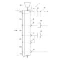
本実施に係るフェロコークス製造設備に用いる竪型シャフト炉1は、シャフト炉本体3における低温乾留ゾーン5aと高温乾留ゾーン5bとからなる乾留ゾーン5で成型物の乾留と還元を、下部の冷却ゾーン7でフェロコークスの冷却を行なう竪型シャフト炉1であって、シャフト炉本体3の側方であって低温乾留ゾーン5aの下部に相当する位置に低温ガス吹き込み羽口9を、シャフト炉本体3の側方であって高温乾留ゾーン5bの中間部および下部に相当する位置に高温ガス吹き込み羽口11および13を有し、シャフト炉本体3の側方であって冷却ゾーン7の下部に相当する位置に冷却ガス吹き込み羽口15を有し、シャフト炉本体3の炉頂部に成型物の装入口17と炉内ガスを排出する炉内ガス排出口19とを有し、シャフト炉本体3の下部にフェロコークスを排出するフェロコークス排出口21を有している。
The
シャフト炉本体3の上方には、装入口17に装入物を装入するための成型物装入装置23が設置されている。また、炉内ガス排出口19に接続される排出ガス配管には、第1循環ガス冷却装置25、第2循環ガス冷却装置27が接続されている。また、第2循環ガス冷却装置27で冷却された循環ガスを低温ガスとして利用するために低温加熱する低温ガス加熱装置29と、第2循環ガス冷却装置27で冷却された循環ガスを高温ガスとして利用するために高温加熱する高温ガス加熱装置31とを備えている。
Above the
上記のように構成された竪型シャフト炉1を用いてフェロコークスを製造する製造方法を説明する。
フェロコークスを製造する際には、炭素含有物質と鉄含有物質との成型物を生成し、生成した成型物を成型物装入装置23を用いてシャフト炉本体3の装入口17から装入する。装入された成型物は、乾留ゾーン5で乾留された後に冷却ゾーン7で冷却されシャフト炉本体下部のフェロコークス排出口21からフェロコークスとして排出される。
低温ガス吹き込み羽口9と高温ガス吹き込み羽口11および13とから成型物を乾留するための加熱ガスを吹き込む。高温ガス吹き込み羽口11および13からは低温ガス吹き込み羽口9から吹き込まれるガスより温度の高い高温ガスが吹き込まれる。高温ガス吹き込み羽口11および13から吹き込まれる高温ガスは、ほぼ温度の同じガスを吹き込むことで、炉内における高温ガス吹込み羽口間に高温の均熱帯を形成する。
フェロコークスを冷却するための冷却ガスは、冷却ガス吹き込み羽口15から吹き込まれる。吹き込まれたガスは、炉頂部の炉内ガスの排出口のみから排出される。
低温ガス吹き込み羽口9は、炉長方向の中心位置よりも上方に設置され、その下方に高温ガス吹き込み羽口11および13、冷却ガス吹き込み羽口15が設置される。
The manufacturing method which manufactures ferro-coke using the
When manufacturing ferro-coke, a molded product of a carbon-containing material and an iron-containing material is generated, and the generated molded product is charged from the charging
A heating gas for dry distillation of the molded product is blown from the low temperature
The cooling gas for cooling the ferro-coke is blown from the cooling
The cold
炉内の高さ方向において所定の長さを有する高温均熱帯5cを形成するための高温ガス吹き込み羽口11および13は、炉長方向の中心位置よりも下方に設置される。ここで、高温ガス吹込み羽口11および13の間に形成される高温均熱帯5cの所定長さとは、ストックラインレベル(原料装入基準レベル)からフェロコークス排出口までの長さの8〜33%となるように設定されることが好ましい。高温均熱帯5cの高さ方向における長さが炉長の8%未満の場合、石炭の乾留および鉱石を還元するために必要な熱量が得られず生産性が悪くなる。一方、高温均熱帯5cの高さ方向における長さが炉長の33%を超える場合、低温乾留ゾーン5aでの昇温速度が急激に大きくなるために熱割れが発生し、さらに冷却ゾーン7での冷却が不十分となり、フェロコークス排出口21以降での冷却設備が別途必要になるため経済的ではない。
High temperature
低温ガス吹き込み羽口9から吹き込む低温ガスは炉頂ガス温度およびシャフト炉内の固体の昇温速度調整のために吹き込むガスであり、400〜700℃程度とするのが好ましい。
また、高温ガス吹き込み羽口11および13から吹き込む高温ガスは、固体の最高温度への昇温のために吹き込むガスであり、800〜1000℃程度とするのが好ましい。
また、冷却ガス吹き込み羽口15から吹き込む冷却ガスは、炉内での乾留により製造されたフェロコークスを冷却するために吹き込むガスであり、25〜80℃程度とするのが好ましい。
The low-temperature gas blown from the low-temperature gas blow-in
Moreover, the high temperature gas blown from the high temperature
Moreover, the cooling gas blown from the cooling gas blown
炉頂部の炉内ガス排出口19から排出された炉内ガスは、循環ガス冷却装置25、27により冷却されて、一部は低温ガス加熱装置29により加熱されて低温ガス吹き込み羽口9から炉内に吹き込まれ、また、一部は高温ガス加熱装置31により加熱されて高温ガス吹き込み羽口11および13から炉内に吹き込まれ、残部は冷却ガス吹き込み羽口15から炉内に吹き込まれる。
The in-furnace gas discharged from the in-furnace
以上のように、本実施の形態では、高さの異なる位置に設置された4段羽口を有し、炉頂部以外にガスの排出口を有していない竪型シャフト炉1を用いて、低温乾留ゾーン5aの下部に設置された低温ガス吹き込み羽口9から低温ガスを、高温乾留ゾーン5bの中間部および下部に設置された高温ガス吹き込み羽口11および13から高温ガスを、冷却ゾーン7の下部に設置された冷却ガス吹き込み羽口15から冷却ガスを吹き込むことで、炭素含有物質と鉄含有物質との成型物を連続的に乾留してフェロコークスを製造する。
As described above, in the present embodiment, using the
本実施の形態では、炉内ガスの排出は炉頂部のみとしているので、特許文献2に示されたもののようにエジェクターで抜き出したガスと炉頂からのガスを混合して加熱用熱媒体ガスとしてシャフト炉内に再び戻すという複雑なことをする必要がなく、炉内のガス流れも炉下部から炉上部への一方向となり設備的にも簡便となり、冷却ガス吹き込み羽口15のガス温度調整のためのガス量調整など複雑な操業を行う必要もない。
さらに、高温ガス吹き込み羽口を二段にすることによって、炉内における高温ガス吹き込み羽口間は高さ方向に高温均熱帯5cが形成され、石炭の乾留に加えて酸化鉄の還元も行う必要があるフェロコークスの製造に適した構造と言える。
In the present embodiment, the discharge of the gas in the furnace is made only at the top of the furnace, so the gas extracted from the ejector and the gas from the top of the furnace are mixed as the heating medium gas for heating as shown in
Furthermore, by forming the hot gas blowing tuyere in two stages, a high
なお、上記の実施の形態では、高温ガス加熱装置31によって加熱された高温ガスを途中で分岐して高温ガス吹き込み羽口11、13のそれぞれに供給するようにしているので、各高温ガス吹き込み羽口11、13に供給されるガス温度は略同一となり、炉内においても高温ガス吹込み羽口間に高温均熱帯5cを容易に形成できる。
もっとも、高温ガス吹き込み羽口11、13から同一温度のガスを吹き込んだとしても、装入物は上方から熱の供給を受けながら下方に移動するとともに、鉄鉱石の還元反応が生じるため、炉内の上部より下部の方が若干高温になり、厳密には炉内の上下で温度勾配ができる。したがって、本明細書で高温均熱帯を形成すると称しているのは、厳密に同一温度領域を形成するという趣旨ではなく、装入物の最高温度への昇温のために必要な温度領域としての意義のある温度領域を形成するという趣旨であり、例えば装入物の温度が800〜1000℃程度の範囲にあればよい。
In the above embodiment, the high-temperature gas heated by the high-temperature
However, even if the gas at the same temperature is blown from the hot
また、高温ガス吹き込み羽口11、13から吹き込む高温ガスは同一温度である必要はなく、例えば上側の高温ガス吹き込み羽口11から吹き込むガス温度を下側の高温ガス吹き込み羽口13から吹き込むガス温度よりも高温にしてもよい。
ガス温度の調整方法としては、例えば比較的低温側の羽口13側から吹き込む高温ガスに、吹込み前に低温ガスを混入させて吹込み温度を調整するようにすればよい。具体的には、低温ガス加熱装置29から吐出される低温ガスの一部を、羽口13に供給する高温ガスに混入するための配管を設け、該配管に流量調整弁を設けるようにすればよい。このような流量調整弁や配管が本発明の流量調整装置として機能する。
The high temperature gas blown from the high temperature
As a method for adjusting the gas temperature, for example, a low temperature gas may be mixed into a high temperature gas blown from a relatively
また、ガス温度と同様に吹き込みガス量も同一である必要はなく、所定の温度領域を形成するために高温ガス吹き込み羽口11、13にガス量偏差をつけてもよい。
ガス量偏差を設ける方法としては、羽口11、13に高温ガスを供給する配管に流量調整弁を設けるようにすればよい。この流量調整弁が本発明の流量調整装置とし機能する。
Further, the amount of the blown gas does not have to be the same as the gas temperature, and the high temperature gas blown
As a method of providing the gas amount deviation, a flow rate adjusting valve may be provided in a pipe for supplying high temperature gas to the
羽口11、13から吹き込む高温ガスの流量や温度を調整可能にすることで、炉内の成型物の温度制御が可能となる。温度制御をより確実に行うため羽口間にガス温度を計測する温度計測装置を設置して、該温度計測装置の計測値に基づいて羽口11、13から吹き込む高温ガスの流量や温度を調整するようにするのが好ましい。なお、成型物の温度を計測する温度計測装置の例としては、装入物の落下による損傷を避けるため、炉壁近傍に熱電対等を差し込むようにしたものが挙げられる。
By making the flow rate and temperature of the hot gas blown from the
なお、ガス流量を調整可能にすることで、下記に示すような操業が可能になる。
フェロコークスの冷却を促進するために、下側の高温ガス吹き込み羽口13の吹き込みガス量を上側の高温ガス吹き込み羽口11の吹き込みガス量よりも低くし、所定の温度領域を上方に形成させ、冷却ゾーン7を炉長方向に長くとることもできる。
高温ガス吹き込み羽口を二段にすることによって、結果的に全吹き込みガス量を抑制し、ガス処理系の設備規模を小さくすることが可能となる。
In addition, by making the gas flow rate adjustable, the following operation becomes possible.
In order to promote cooling of the ferro-coke, the amount of gas blown in the lower hot
By using two stages of hot gas blowing tuyere, the total amount of blowing gas can be suppressed as a result, and the equipment scale of the gas processing system can be reduced.
本発明の効果を確認するために、図4に示したフェロコークス製造試験装置を用いて、高温ガス吹き込み羽口が二段の場合と一段の場合についてのフェロコークスの製造試験を実施した。なお、図4において図1と同一部分には同一の符号を付してある。
図4に示した竪型シャフト炉1は、全長が13.0m、炉上端面からストックラインレベルまでが0.65m、ストックラインレベルから低温ガス吹き込み羽口9の中心までが3.5m、低温ガス吹き込み羽口9の中心から上段の高温ガス吹き込み羽口11の中心までが3.0m、高温ガス吹き込み羽口11の中心から下段の高温ガス吹き込み羽口13の中心までが2.0m、下段の高温ガス吹き込み羽口13の中心から冷却ガス吹き込み羽口の中心までが2.85m、冷却ガス吹き込み羽口の中心から排出口21までが1.0mに設定されている。
また、竪型シャフト炉1の断面積は1.67m2、装入物の降下速度は1.6m/hであった。表1にフェロコークス製造における操業諸元を、表2に製造したフェロコークスの性状を示す。
In order to confirm the effect of the present invention, a ferro-coke production test was carried out using the ferro-coke production test apparatus shown in FIG. In FIG. 4, the same parts as those in FIG. 1 are denoted by the same reference numerals.
The
Further, the cross-sectional area of the

今回のフェロコークス製造試験装置での温度、降下速度では、乾留後の強度をドラム強度指数で表し、DI150/6(150回転後の6mm指数)の目標値を82としている。また、還元率の目標値は80%としている。
表2に示したように、高温ガス吹き込み羽口を二段化したものでは、強度、還元率ともに目標値を超えているが、高温ガス吹き込み羽口が一段では強度に関しては目標値を超えているが、還元率では目標値に至っていない。これは、900℃の温度域での滞留時間が十分に確保できず、その結果、還元率が低い値に留まったものと推察される。
In this ferro-coke production test equipment, the strength after dry distillation is expressed as a drum strength index, and the target value of DI150 / 6 (6 mm index after 150 rotations) is 82. The target value of the reduction rate is 80%.
As shown in Table 2, when the hot gas blowing tuyere has two stages, the strength and the reduction rate exceed the target values, but when the hot gas blowing tuyere has one stage, the strength exceeds the target value. However, the return rate has not reached the target value. This is presumed that the residence time in the temperature range of 900 ° C. could not be sufficiently secured, and as a result, the reduction rate remained at a low value.
本実験から、高温ガス吹き込み羽口を二段にして、高温均熱帯を炉内に形成することで、大きな吸熱反応を伴うフェロコークス製造を安定して行うことができることが確認された。 From this experiment, it was confirmed that ferro-coke production with a large endothermic reaction can be performed stably by forming a high-temperature gas blowing tuyere in two stages and forming a high-temperature soaking zone in the furnace.
なお、上記の例では、高温ガス吹き込み羽口を二段にする例を示したが、高温ガス吹き込み羽口を三段以上設けるようにしてもよい。
また、上記の例では、高温均熱帯を形成するための高温ガス吹き込み羽口11および13を炉長方向の中心位置よりも下方に設置する例を示したが、高温均熱帯が炉長方向中心位置よりも下方に形成されるのであれば、例えば高温ガスの吹込み方向を制御することにより、上側の高温ガス吹き込み羽口11が炉長方向中心位置以上の高さにあってもよい。
In the above example, the hot gas blowing tuyere has two stages, but three or more hot gas blowing tuyere may be provided.
Further, in the above example, the hot
なお、上記の実施例の結果から、高温ガス吹き込み羽口を二段にして高温均熱帯を形成することによる効果は、竪型シャフト炉をフェロコークス製造の際に乾留炉として用いる場合のみならず、例えば石炭、廃棄物等の装入物を燃焼、ガス化させる燃焼・ガス化炉、プラスチックやバイオマスなどをガス化するガス化炉、金属酸化物を還元する還元炉、スクラップなどを溶融する溶融炉として用いる場合にも得られるものである。 From the results of the above examples, the effect of forming a high temperature soaking zone with two stages of hot gas blowing tuyere is not only used when a vertical shaft furnace is used as a dry distillation furnace in ferro-coke production. For example, combustion and gasification furnaces that combust and gasify charges such as coal and waste, gasification furnaces that gasify plastics and biomass, reduction furnaces that reduce metal oxides, melting that melts scraps, etc. It can also be obtained when used as a furnace.
1 竪型シャフト炉
3 シャフト炉本体
5 乾留ゾーン
5a 低温乾留ゾーン
5b 高温乾留ゾーン
5c 高温均熱帯
7 冷却ゾーン
9 低温ガス吹き込み羽口
11、13 高温ガス吹き込み羽口
15 冷却ガス吹き込み羽口
17 装入口
19 炉内ガス排出口
21 フェロコークス排出口
23 成型物装入装置
25 第1循環ガス冷却装置
27 第2循環ガス冷却装置
29 低温ガス加熱装置
31 高温ガス加熱装置
DESCRIPTION OF
Claims (10)
炉長方向の中心位置よりも下方に所定長さの高温均熱帯を形成するために、高温ガス吹き込み羽口を炉長方向に複数段設けたことを特徴とする竪型シャフト炉。 A vertical shaft furnace for continuously producing a target product by burning, gasifying, dry distillation or reducing a charge charged from the top of the furnace,
A vertical shaft furnace characterized in that a plurality of stages of hot gas blowing tuyere are provided in the furnace length direction in order to form a high temperature soaking zone of a predetermined length below the center position in the furnace length direction.
炉頂部から炭素含有物質と鉄含有物質の成型物を装入し、前記低温ガス吹き込み羽口から成型物を乾留するための低温ガスを吹き込み、該低温ガスより温度の高いガスを高温ガス吹き込み羽口から吹き込み、製品としてのフェロコークスを冷却するための冷却ガスを冷却ガス吹き込み羽口から吹き込み、炉頂部の炉内ガス排出口からガスを排出するようにしたことを特徴とするフェロコークスの製造方法。 In order to form a high temperature soaking zone of a predetermined length below the center position in the furnace length direction, a hot gas blowing tuyere provided with a plurality of stages in the furnace length direction to blow in high temperature gas, and the center position in the furnace length direction A cold gas blowing tuyere for blowing low temperature gas provided above, a cooling gas blowing tuyere for blowing cooling gas provided below the hot gas blowing tuyere, and provided at the top of the furnace A method for producing ferro-coke using a vertical shaft furnace provided with an in-furnace gas discharge port for discharging the in-furnace gas,
A molded product of carbon-containing material and iron-containing material is charged from the top of the furnace, a low-temperature gas is blown from the low-temperature gas blowing tuyere, and a gas higher in temperature than the low-temperature gas is blown into the hot-gas blowing feather. Manufacture of ferro-coke, which is blown from the mouth and cooling gas for cooling the product ferro-coke is blown from the cooling gas blow-down tuyere and discharged from the furnace gas outlet at the top of the furnace. Method.
Priority Applications (1)
| Application Number | Priority Date | Filing Date | Title |
|---|---|---|---|
| JP2011041068A JP4860003B2 (en) | 2010-03-29 | 2011-02-28 | Vertical shaft furnace, ferro-coke manufacturing equipment provided with the vertical shaft furnace, and ferro-coke manufacturing method using the ferro-coke manufacturing equipment |
Applications Claiming Priority (3)
| Application Number | Priority Date | Filing Date | Title |
|---|---|---|---|
| JP2010074481 | 2010-03-29 | ||
| JP2010074481 | 2010-03-29 | ||
| JP2011041068A JP4860003B2 (en) | 2010-03-29 | 2011-02-28 | Vertical shaft furnace, ferro-coke manufacturing equipment provided with the vertical shaft furnace, and ferro-coke manufacturing method using the ferro-coke manufacturing equipment |
Publications (2)
| Publication Number | Publication Date |
|---|---|
| JP2011226766A JP2011226766A (en) | 2011-11-10 |
| JP4860003B2 true JP4860003B2 (en) | 2012-01-25 |
Family
ID=44712231
Family Applications (1)
| Application Number | Title | Priority Date | Filing Date |
|---|---|---|---|
| JP2011041068A Active JP4860003B2 (en) | 2010-03-29 | 2011-02-28 | Vertical shaft furnace, ferro-coke manufacturing equipment provided with the vertical shaft furnace, and ferro-coke manufacturing method using the ferro-coke manufacturing equipment |
Country Status (5)
| Country | Link |
|---|---|
| EP (1) | EP2554632B1 (en) |
| JP (1) | JP4860003B2 (en) |
| KR (1) | KR101475582B1 (en) |
| CN (1) | CN102822315B (en) |
| WO (1) | WO2011122535A1 (en) |
Families Citing this family (11)
| Publication number | Priority date | Publication date | Assignee | Title |
|---|---|---|---|---|
| JP4666114B2 (en) * | 2009-08-10 | 2011-04-06 | Jfeスチール株式会社 | Ferro-coke manufacturing method and manufacturing apparatus |
| JP2013089352A (en) | 2011-10-14 | 2013-05-13 | Honda Motor Co Ltd | Fuel cell system and stopping method therefor |
| JP5900026B2 (en) * | 2012-03-02 | 2016-04-06 | Jfeスチール株式会社 | Method and apparatus for estimating furnace temperature distribution |
| JP5900025B2 (en) * | 2012-03-02 | 2016-04-06 | Jfeスチール株式会社 | Method and apparatus for estimating furnace temperature distribution |
| JP5900027B2 (en) * | 2012-03-02 | 2016-04-06 | Jfeスチール株式会社 | Method and apparatus for estimating furnace temperature distribution |
| JP6094127B2 (en) * | 2012-10-02 | 2017-03-15 | Jfeスチール株式会社 | Temperature distribution estimation method and temperature distribution estimation apparatus |
| JP5900386B2 (en) * | 2013-03-13 | 2016-04-06 | Jfeスチール株式会社 | Control method and control device for dry distillation furnace |
| CN106635067A (en) * | 2016-11-24 | 2017-05-10 | 武汉科思瑞迪科技有限公司 | Shaft furnace process for producing iron coke |
| CN110129500B (en) * | 2019-06-05 | 2020-09-15 | 东北大学 | Preparation method and preparation system of iron coke |
| CN111004638B (en) * | 2019-12-31 | 2021-04-30 | 中冶南方工程技术有限公司 | Method for determining size of iron coke production shaft furnace |
| US12084730B2 (en) * | 2020-03-24 | 2024-09-10 | Midrex Technologies, Inc. | Methods and systems for increasing the carbon content of direct reduced iron in a reduction furnace |
Family Cites Families (12)
| Publication number | Priority date | Publication date | Assignee | Title |
|---|---|---|---|---|
| JPS5223102A (en) | 1975-08-18 | 1977-02-21 | Nippon Steel Corp | Process for manufacturing formed coke |
| JPS54143402A (en) * | 1978-04-28 | 1979-11-08 | Nippon Steel Corp | Manufacturing of metallurgical formed coke |
| JPS606390B2 (en) | 1979-10-17 | 1985-02-18 | 社団法人 日本鉄鋼連盟 | Gas circulation device in vertical molded coke carbonization furnace |
| JPH0797577A (en) * | 1993-09-28 | 1995-04-11 | Kawasaki Steel Corp | Method for production shaped coke |
| JPH07126648A (en) * | 1993-10-29 | 1995-05-16 | Kawasaki Steel Corp | Method for removing soot between gas mixing chamber and high-temperature tuyere in vertically formed coke dry distillation oven |
| JP3487912B2 (en) * | 1994-07-04 | 2004-01-19 | 新日本製鐵株式会社 | Molded coke containing iron ore, method for producing molded coke, and method for operating blast furnace |
| CN1036075C (en) * | 1994-08-27 | 1997-10-08 | 冶金工业部钢铁研究总院 | Fusion reducing iron smelting method and its equipment |
| CN2259246Y (en) * | 1995-12-22 | 1997-08-13 | 乔志海 | External firing coal oxidized pellet ore shaft furnace |
| KR100531767B1 (en) * | 2004-02-18 | 2005-11-28 | 주식회사 포스코건설 | H2S Gas Exclusion Method and The Apparatus of Coke Oven Gas |
| CA2651463C (en) * | 2006-05-05 | 2014-12-02 | Bioecon International Holding N.V. | Improved process for converting carbon-based energy carrier material |
| JP4666112B2 (en) * | 2009-07-29 | 2011-04-06 | Jfeスチール株式会社 | Ferro-coke manufacturing method |
| JP4666114B2 (en) * | 2009-08-10 | 2011-04-06 | Jfeスチール株式会社 | Ferro-coke manufacturing method and manufacturing apparatus |
-
2011
- 2011-02-28 JP JP2011041068A patent/JP4860003B2/en active Active
- 2011-03-28 EP EP11762759.6A patent/EP2554632B1/en active Active
- 2011-03-28 CN CN201180015873.4A patent/CN102822315B/en active Active
- 2011-03-28 WO PCT/JP2011/057559 patent/WO2011122535A1/en active Application Filing
- 2011-03-28 KR KR1020127024775A patent/KR101475582B1/en active IP Right Grant
Also Published As
| Publication number | Publication date |
|---|---|
| EP2554632B1 (en) | 2018-10-10 |
| WO2011122535A1 (en) | 2011-10-06 |
| EP2554632A4 (en) | 2014-06-11 |
| CN102822315A (en) | 2012-12-12 |
| CN102822315B (en) | 2016-08-03 |
| EP2554632A1 (en) | 2013-02-06 |
| JP2011226766A (en) | 2011-11-10 |
| KR20120120470A (en) | 2012-11-01 |
| KR101475582B1 (en) | 2014-12-22 |
Similar Documents
| Publication | Publication Date | Title |
|---|---|---|
| JP4860003B2 (en) | Vertical shaft furnace, ferro-coke manufacturing equipment provided with the vertical shaft furnace, and ferro-coke manufacturing method using the ferro-coke manufacturing equipment | |
| US8690987B2 (en) | Method and apparatus for producing carbon iron composite | |
| JP2014132108A (en) | Method for operating blast furnace and method for manufacturing molten iron | |
| JP4801732B2 (en) | How to preheat iron agglomerates | |
| JP5504650B2 (en) | Molded coke manufacturing equipment and molded coke manufacturing method | |
| JP6683212B2 (en) | Vertical carbonization furnace for ferro-coke production | |
| CN104034151A (en) | Cupola furnace with high thermal efficiency | |
| KR101511720B1 (en) | Manufacturing apparatus for molten metal and method thereof | |
| JP5921887B2 (en) | Method and apparatus for producing molded coke | |
| US20180355448A1 (en) | Flash ironmaking system and method | |
| CN203203381U (en) | Furnace bar type natural gas cupola carbon heat exchange bed | |
| JP6036744B2 (en) | Tubular structure of vertical furnace, vertical furnace and method for producing dry distillation product | |
| CN115418433B (en) | High-temperature furnace drying method for opening new converter | |
| JP5504731B2 (en) | Ferro-coke production equipment | |
| JP2003003172A (en) | Method for improving coke | |
| CN208183008U (en) | A kind of pyrogenic process enrichment furnace | |
| JP2024085078A (en) | Operation method of blast furnace | |
| JPH0665578A (en) | Production of metallurgical formed coke | |
| JPH04359088A (en) | Production of molded coke for metallurgy | |
| JP2016502598A (en) | Two-stage smelting method and apparatus | |
| CN103017509A (en) | Furnace bar type natural gas cupola carbon heat exchange bed | |
| CN110595200A (en) | Energy-saving cupola furnace | |
| US1486370A (en) | Hot-gas process for the reduction and smelting of metals | |
| CN102168188A (en) | Antimony flotation concentrate flash oxidization primary refining production process and flash antimony metallurgical furnace | |
| Koverzin et al. | Controlling the blast-furnace hearth |
Legal Events
| Date | Code | Title | Description |
|---|---|---|---|
| A621 | Written request for application examination |
Free format text: JAPANESE INTERMEDIATE CODE: A621 Effective date: 20110929 |
|
| A871 | Explanation of circumstances concerning accelerated examination |
Free format text: JAPANESE INTERMEDIATE CODE: A871 Effective date: 20110929 |
|
| TRDD | Decision of grant or rejection written | ||
| A975 | Report on accelerated examination |
Free format text: JAPANESE INTERMEDIATE CODE: A971005 Effective date: 20111026 |
|
| A01 | Written decision to grant a patent or to grant a registration (utility model) |
Free format text: JAPANESE INTERMEDIATE CODE: A01 Effective date: 20111101 |
|
| A01 | Written decision to grant a patent or to grant a registration (utility model) |
Free format text: JAPANESE INTERMEDIATE CODE: A01 |
|
| A61 | First payment of annual fees (during grant procedure) |
Free format text: JAPANESE INTERMEDIATE CODE: A61 Effective date: 20111101 |
|
| R150 | Certificate of patent or registration of utility model |
Ref document number: 4860003 Country of ref document: JP Free format text: JAPANESE INTERMEDIATE CODE: R150 Free format text: JAPANESE INTERMEDIATE CODE: R150 |
|
| FPAY | Renewal fee payment (event date is renewal date of database) |
Free format text: PAYMENT UNTIL: 20141111 Year of fee payment: 3 |
|
| S531 | Written request for registration of change of domicile |
Free format text: JAPANESE INTERMEDIATE CODE: R313531 |
|
| R350 | Written notification of registration of transfer |
Free format text: JAPANESE INTERMEDIATE CODE: R350 |
|
| R250 | Receipt of annual fees |
Free format text: JAPANESE INTERMEDIATE CODE: R250 |
|
| R250 | Receipt of annual fees |
Free format text: JAPANESE INTERMEDIATE CODE: R250 |
|
| R250 | Receipt of annual fees |
Free format text: JAPANESE INTERMEDIATE CODE: R250 |