EP2554632B1 - Ferro-coke production facility comprising a vertical shaft furnace and method for producing ferro-coke - Google Patents
Ferro-coke production facility comprising a vertical shaft furnace and method for producing ferro-coke Download PDFInfo
- Publication number
- EP2554632B1 EP2554632B1 EP11762759.6A EP11762759A EP2554632B1 EP 2554632 B1 EP2554632 B1 EP 2554632B1 EP 11762759 A EP11762759 A EP 11762759A EP 2554632 B1 EP2554632 B1 EP 2554632B1
- Authority
- EP
- European Patent Office
- Prior art keywords
- temperature
- furnace
- gas
- ferrocoke
- gas injection
- Prior art date
- Legal status (The legal status is an assumption and is not a legal conclusion. Google has not performed a legal analysis and makes no representation as to the accuracy of the status listed.)
- Active
Links
Images


Classifications
-
- C—CHEMISTRY; METALLURGY
- C10—PETROLEUM, GAS OR COKE INDUSTRIES; TECHNICAL GASES CONTAINING CARBON MONOXIDE; FUELS; LUBRICANTS; PEAT
- C10B—DESTRUCTIVE DISTILLATION OF CARBONACEOUS MATERIALS FOR PRODUCTION OF GAS, COKE, TAR, OR SIMILAR MATERIALS
- C10B49/00—Destructive distillation of solid carbonaceous materials by direct heating with heat-carrying agents including the partial combustion of the solid material to be treated
- C10B49/02—Destructive distillation of solid carbonaceous materials by direct heating with heat-carrying agents including the partial combustion of the solid material to be treated with hot gases or vapours, e.g. hot gases obtained by partial combustion of the charge
- C10B49/04—Destructive distillation of solid carbonaceous materials by direct heating with heat-carrying agents including the partial combustion of the solid material to be treated with hot gases or vapours, e.g. hot gases obtained by partial combustion of the charge while moving the solid material to be treated
-
- C—CHEMISTRY; METALLURGY
- C10—PETROLEUM, GAS OR COKE INDUSTRIES; TECHNICAL GASES CONTAINING CARBON MONOXIDE; FUELS; LUBRICANTS; PEAT
- C10B—DESTRUCTIVE DISTILLATION OF CARBONACEOUS MATERIALS FOR PRODUCTION OF GAS, COKE, TAR, OR SIMILAR MATERIALS
- C10B3/00—Coke ovens with vertical chambers
-
- C—CHEMISTRY; METALLURGY
- C10—PETROLEUM, GAS OR COKE INDUSTRIES; TECHNICAL GASES CONTAINING CARBON MONOXIDE; FUELS; LUBRICANTS; PEAT
- C10B—DESTRUCTIVE DISTILLATION OF CARBONACEOUS MATERIALS FOR PRODUCTION OF GAS, COKE, TAR, OR SIMILAR MATERIALS
- C10B53/00—Destructive distillation, specially adapted for particular solid raw materials or solid raw materials in special form
- C10B53/08—Destructive distillation, specially adapted for particular solid raw materials or solid raw materials in special form in the form of briquettes, lumps and the like
-
- C—CHEMISTRY; METALLURGY
- C10—PETROLEUM, GAS OR COKE INDUSTRIES; TECHNICAL GASES CONTAINING CARBON MONOXIDE; FUELS; LUBRICANTS; PEAT
- C10B—DESTRUCTIVE DISTILLATION OF CARBONACEOUS MATERIALS FOR PRODUCTION OF GAS, COKE, TAR, OR SIMILAR MATERIALS
- C10B57/00—Other carbonising or coking processes; Features of destructive distillation processes in general
- C10B57/04—Other carbonising or coking processes; Features of destructive distillation processes in general using charges of special composition
- C10B57/06—Other carbonising or coking processes; Features of destructive distillation processes in general using charges of special composition containing additives
-
- C—CHEMISTRY; METALLURGY
- C21—METALLURGY OF IRON
- C21B—MANUFACTURE OF IRON OR STEEL
- C21B11/00—Making pig-iron other than in blast furnaces
- C21B11/02—Making pig-iron other than in blast furnaces in low shaft furnaces or shaft furnaces
-
- C—CHEMISTRY; METALLURGY
- C21—METALLURGY OF IRON
- C21B—MANUFACTURE OF IRON OR STEEL
- C21B15/00—Other processes for the manufacture of iron from iron compounds
-
- F—MECHANICAL ENGINEERING; LIGHTING; HEATING; WEAPONS; BLASTING
- F27—FURNACES; KILNS; OVENS; RETORTS
- F27B—FURNACES, KILNS, OVENS, OR RETORTS IN GENERAL; OPEN SINTERING OR LIKE APPARATUS
- F27B1/00—Shaft or like vertical or substantially vertical furnaces
- F27B1/10—Details, accessories, or equipment peculiar to furnaces of these types
- F27B1/16—Arrangements of tuyeres
-
- Y—GENERAL TAGGING OF NEW TECHNOLOGICAL DEVELOPMENTS; GENERAL TAGGING OF CROSS-SECTIONAL TECHNOLOGIES SPANNING OVER SEVERAL SECTIONS OF THE IPC; TECHNICAL SUBJECTS COVERED BY FORMER USPC CROSS-REFERENCE ART COLLECTIONS [XRACs] AND DIGESTS
- Y02—TECHNOLOGIES OR APPLICATIONS FOR MITIGATION OR ADAPTATION AGAINST CLIMATE CHANGE
- Y02P—CLIMATE CHANGE MITIGATION TECHNOLOGIES IN THE PRODUCTION OR PROCESSING OF GOODS
- Y02P10/00—Technologies related to metal processing
- Y02P10/10—Reduction of greenhouse gas [GHG] emissions
- Y02P10/134—Reduction of greenhouse gas [GHG] emissions by avoiding CO2, e.g. using hydrogen
Definitions
- the present invention relates to a ferrocoke production facility comprising a vertical shaft furnace that subjects a burden material fed from a furnace top to combustion, gasification, carbonization, or reduction to continuously produce ferrocoke, and a ferrocoke production method using the facility.
- metallurgical coke produced by carbonization of coal in a coke furnace.
- the metallurgical coke plays the roles of a spacer for providing adequate gas permeability in the blast furnace, a reducing agent, a heat source, and the like.
- a coke production method in relation to a chamber furnace coke production method there has been developed a continuous formed coke production method.
- a vertical shaft furnace made of chamotte bricks, not silica bricks is used as a carbonization furnace, and coal is briquetted with a predetermined size by cold forming, and the briquetted coal is fed into the vertical shaft furnace to carbonize the briquetted coal by heating with a circulating heat carrier gas, thereby producing formed coke.
- the vertical shaft furnace has proven to be capable of producing coke with a strength equivalent to that of coke from a general chamber-type coke furnace, even if a large amount of non- or slightly-caking coal is used, which is abundant in resource reserve and less expensive.
- the coal used is high in caking property, the formed coal is softened and fused in the shaft furnace, which makes the shaft furnace difficult to operate and results in deteriorated quality of coke products with deformation, breakage, and the like.
- Patent Literature 1 As an example of a continuous formed coke production method, there is a known method disclosed in Patent Literature 1.
- a cooling chamber is provided so as to be directly connected to a carbonization chamber in a carbonization furnace, a top gas in a carbonization furnace is introduced as a cooling gas to the lower part of the cooling chamber, most part of the gas having passed through the cooling chamber is discharged from the upper part of the cooling chamber, and the discharged gas is supplied as a heating medium gas to an inlet at the intermediate part of the carbonization furnace.
- Patent Literature 1 In the method disclosed in Patent Literature 1, it is needed that the gas having passed through a red-hot coke layer in the cooling chamber is sucked by some means from the cooling chamber in the carbonization furnace, and the gas is adjusted in flow rate and temperature and is increased in pressure to meet a pressure necessary for blowing the gas into a low-temperature carbonization chamber tuyere. Accordingly, to conduct the pressure increase in an economical facility, there has been suggested a method by which part of furnace top gas is increased in pressure by a blower, the pressure-increased gas is used as a driver gas to suck a cooling chamber outlet gas, and an ejector is utilized to supply the discharged gas to a lower-temperature carbonization chamber tuyere (see Patent Literature 2).
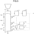
- FIG. 5 is a simplified diagram of FIG. 1 in Patent Literature 2.
- the continuous formed coke production method disclosed in Patent Literature 2 will be described with reference to FIG. 5 .
- An agglomerated coal 101 is fed into a vertical shaft furnace 105, which is formed with a low-temperature carbonization chamber 102, a high-temperature carbonization chamber 103, and a cooling chamber 104, from a furnace top into a furnace inside, and is carbonized by a heating thermal medium gas introduced from tuyeres 106 and 107 in the course of descending in the furnace. Further, the carbonized agglomerated coal 101 is cooled by a cooling gas introduced from a cooling gas introduction port 108 and discharged from a discharge port 109, and then is discharged as formed coke 110 from the lower part of the carbonization furnace.
- the gas extracted from the furnace top is cooled by a direct cooler 111 and an indirect cooler 112, and is increased in pressure by a blower not illustrated, and then a part of the gas is guided as a recovery gas to outside the system and the remaining part of the gas is circulated as a circulating gas in the system.
- a part of the circulating gas is introduced as a cooling gas from the cooling gas introduction port 108 into the cooling chamber 104.
- Another part of the circulating gas is increased in pressure by a blower not illustrated, and is introduced as a high-temperature carbonization thermal medium gas heated by a heater 115, from the tuyere 107 into the carbonization furnace.
- the remaining part of the circulating gas is adjusted in pressure, flow rate, and temperature, by a blower not illustrated and a heater 117, and is guided to an ejector 118 as a drive gas for the ejector 118.
- the ejector 118 sucks a cooling zone outlet gas from the discharge port 109, and mixes the sucked gas with the drive gas, and increases the mixed gas in pressure, and introduces the gas as a low-temperature carbonization thermal medium gas from the tuyere 106 into the carbonization furnace.
- Non Patent Literature 1 there has been examined a ferrocoke production method including a forming step of agglomerating coal and a carbonization step of, after the forming step, carbonizing the agglomerated coal in a general chamber-type coke furnace, thereby obtaining ferrocoke products.
- the general chamber-type coke furnace is made of silica bricks, and thus if iron ore is fed into the furnace, the iron ore reacts with silica as a main ingredient of the silica bricks to generate lower-melting-point firelight, which leads to damage of the silica bricks. Therefore, the technique of producing ferrocoke in a chamber-type coke furnace is industrially not utilized under actual circumstances.
- a vertical shaft furnace is used for continuous production of formed coke, not for production of ferrocoke.
- the vertical shaft furnace as disclosed in Patent Literature 2 is made of chamotte bricks, not silica bricks, as described above, it is therefore considered that, if the vertical shaft furnace is used for production of ferrocoke, the problem with the general chamber-type coke furnace using silica bricks will not arise in the vertical shaft furnace. Accordingly, it is conceived that the vertical shaft furnace made of chamotte bricks disclosed in Patent Literature 2, for example, is used at the carbonization step of ferrocoke production.
- the vertical shaft furnace disclosed in Patent Literature 2 is applied to production of ferrocoke, the following various problems remain unsolved.
- Patent Literature 2 the high-temperature gas is introduced for reuse from the tuyere 106 into the low-temperature carbonization chamber 102, and therefore, thermal loss may be generated in the course of the introduction.
- energy saving will be unavoidable and a design concept for lowering energy necessary for production of ferrocoke as much as possible will be required. Therefore, the generation of thermal loss is not considered to be expedient.
- the present invention is devised in light of the foregoing problems, and an object of the present invention is to provide a vertical shaft furnace that allows a simplified facility and uncomplicated operational conditions.
- another object of the present invention is to provide a ferrocoke production facility and a ferrocoke production method that, when a vertical shaft furnace is used as a carbonization furnace for metallurgical ferrocoke, achieves simplification of a facility and operation and reduction of energy usage.
- a ferrocoke production facility includes a vertical shaft furnace that subjects an object fed from a furnace top to combustion, gasification, carbonization, or reduction, thereby to continuously produce a target product, wherein high-temperature gas injection tuyeres configured to inject high-temperature gases of the same temperature are provided in a plurality of stages along furnace length to form a high-temperature soaking zone with a predetermined length below an intermediate position of the furnace along furnace length, wherein the predetermined length of the high-temperature soaking zone is set to 8 to 33% of the furnace length, and wherein a briquetted material of a coal-containing substance and an iron-containing substance is fed from the furnace top part of the vertical shaft furnace to continuously produce ferrocoke as a product.
- a ferrocoke production method for producing ferrocoke uses a ferrocoke production facility comprising a vertical shaft furnace that subjects a burden material fed from a furnace top to combustion, gasification, carbonization, or reduction, thereby to continuously produce a target product, provided with a briquetted material feeder for feeding a briquetted material of a coal-containing substance and an iron-containing substance from the furnace top part of the vertical shaft furnace to continuously produce ferrocoke as a product, further comprising: a plurality of high-temperature gas injection tuyeres, from which high-temperature gases of the same temperature are injected, that is provided along furnace length and injects a high-temperature gas to form a high-temperature soaking zone with a predetermined length below an intermediate position of the furnace along furnace length; a low-temperature gas injection tuyere that is provided above a central position of the furnace along furnace length to inject a low-temperature gas; a cooling
- the ferrocoke production facility comprising a vertical shaft furnace of the present invention
- a vertical shaft furnace that allows a simplified facility and uncomplicated operational conditions.
- the inventors investigated reduction behavior of iron ore in the course of carbonization of a briquetted material, as basic characteristics. Reduction of iron oxide in the process of ferrocoke production can be roughly classified into direct reduction by solid carbon (see Equation (1) below) and gas reduction by an H 2 gas and a CO gas resulting from coal (see Equations (2) and (3) below).
- Equation (1) The direct reduction in Equation (1) involves large endothermic reaction.
- a briquetted material of coal and iron ore was carbonized by increasing a temperature with distribution of N 2 , and the foregoing reduction mode was analyzed from a composition of an exhaust gas.
- the ratio of direct reduction by C (Equation (1)) rose sharply, and the amount of heat absorbed at reduction increased. Therefore, production of ferrocoke requires an operational design in which endothermic reaction with the briquetted material at a temperature of 800°C or more is compensated for.
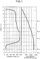
- FIG. 1 illustrates results of calculation in the case of using a ferrocoke production facility of the invention without a cooling gas extraction tuyere and with high-temperature gas injection tuyeres in two stages.
- FIG. 2 illustrates results of calculation in the case of using a ferrocoke production facility without a cooling gas extraction tuyere and with a high-temperature gas injection tuyere in one stage.
- FIGS. 1 and 2 illustrate results of calculation of gas conditions meeting target temperature distribution with a region in which the briquetted material is at a temperature of 900°C for one to two hours.
- code A denotes the position of a low-temperature gas injection tuyere through which a 600°C gas of 800 Nm 3 /t is injected;
- B the position of a high-temperature gas injection tuyere through which a 990°C gas of 950 Nm 3 /t is injected;
- C the position of a high-temperature gas injection tuyere through which a 990°C gas of 950 Nm 3 /t is injected, as with B;
- D the position of a cooling gas injection tuyere through which a 35°C gas of 1987 Nm 3 /t is injected;
- E the position of a ferrocoke discharge port.
- code A denotes the position of a low-temperature gas injection tuyere through which a 500°C gas of 1200 Nm 3 /t is injected; B the position of a high-temperature gas injection tuyere through which a 980°C gas of 2400 Nm 3 /t is injected; D the position of a cooling gas injection tuyere through which a 35°C gas of 1983 Nm 3 /t is injected; and E the position of a ferrocoke discharge port.
- the invention is devised based on the foregoing knowledge obtained by the results of experiments, and specifically, the invention is configured as described below.
- a vertical shaft furnace is used to continuously carbonize a briquetted material of a carbon-containing substance and an iron-containing substance, thereby to produce ferrocoke in which metallic iron is generated in coke.
- the ferrocoke production facility is configured such that a vertical shaft furnace has an area under a stockline level (material charging reference level), which is below a process gas discharge port, is divided into a low-temperature carbonization zone, a high-temperature carbonization zone, and a cooling zone.
- the low-temperature carbonization zone covers from the stockline level (material insertion reference level) to a low-temperature gas injection tuyere, and the high-temperature carbonization zone covers from the low-temperature gas injection tuyere to a high-temperature gas injection tuyere, which is in the lower stage along furnace length, and the cooling zone covers from the high-temperature gas injection tuyere in the lower stage to a cooling gas injection tuyere.
- the ferrocoke production facility is structured so as to supply a heat medium gas from four parts: a lower part of the low-temperature carbonization zone, an intermediate part and lower part of the high-temperature carbonization zone, and a lower part of the cooling zone, and discharges a process gas only from the furnace top part.
- the ferrocoke production facility can be simplified by eliminating a cooling gas extraction tuyere provided at a conventional formed coke production facility.
- FIG. 3 is a configuration example of the ferrocoke production facility according to the embodiment.
- a vertical shaft furnace 1 used in the ferrocoke production facility according to the embodiment subjects a briquetted material to carbonization and reduction in a carbonization zone 5 formed by a low-temperature carbonization zone 5a and a high-temperature carbonization zone 5b in a shaft furnace main body 3, and cools ferrocoke in a cooling zone 7 at a lower part.
- the vertical shaft furnace 1 has a low-temperature gas injection tuyere 9 on a side of the shaft furnace main body 3 at a position corresponding to a lower part of the low-temperature carbonization zone 5a.
- the vertical shaft furnace 1 has high-temperature gas injection tuyeres 11 and 13 on the side of the shaft furnace main body 3 at positions corresponding to an intermediate part and lower part of the high-temperature carbonization zone 5b.
- the vertical shaft furnace 1 has a cooling gas injection tuyere 15 on the side of the shaft furnace main body 3 at a position corresponding to a lower part of the cooling zone 7.
- the vertical shaft furnace 1 has a briquetted material feeding hole 17 and a process gas discharge port 19 for discharging a process gas at a top furnace part of the shaft furnace main body 3.
- the vertical shaft furnace 1 has a ferrocoke discharge port 21 for discharging ferrocoke at the lower part of the shaft furnace main body 3.
- a briquetted material feeder 23 for feeding an object into a feeding hole 17.
- a first circulating gas cooler 25 and a second circulating gas cooler 27 are connected to a discharge gas pipe connected to the process gas discharge port 19.
- a low-temperature gas heater 29 is provided to heat a circulating gas, which is cooled at the second circulating gas cooler 27, at a low temperature for use as a low-temperature gas
- a high-temperature gas heater 31 is provided to heat a circulating gas, which is cooled at the second circulating gas cooler 27, at a high temperature for use as a high-temperature gas.
- the briquetted material feeder 23 feeds a briquetted material generated from a carbon-containing substance and an iron-containing substance, through the feeding hole 17 of the shaft furnace main body 3.
- the fed briquetted material is carbonized in the carbonization zone 5 and cooled in the cooling zone 7, and then discharged as ferrocoke from the ferrocoke discharge port 21 at the lower part of the shaft furnace main body 3.
- the low-temperature gas heater 29 injects a heating gas (low-temperature gas) for carbonization of the briquetted material, from the low-temperature gas injection tuyere 9.
- the high-temperature gas heater 31 injects heating gases (high-temperature gases) for carbonization of the briquetted material, from the high-temperature gas injection tuyeres 11 and 13.
- the high-temperature gases injected from the high-temperature gas injection tuyeres 11 and 13 are higher in temperature than the low-temperature gas injected from the low-temperature gas injection tuyere 9.
- the high-temperature gases injected from the high-temperature gas injection tuyeres 11 and 13 are almost the same in temperature, thereby to form a high-temperature soaking zone between the high-temperature gas injection tuyeres in the furnace.
- the second circulating gas cooler 27 injects a cooling gas for cooling ferrocoke, through the cooling gas injection tuyere 15.
- the injected gases are discharged only from the process gas discharge port at the furnace top part.
- the low-temperature gas injection tuyere 9 is disposed above an intermediate position of the furnace along furnace length, and the high-temperature gas injection tuyeres 11 and 13 and the cooling gas injection tuyere 15 are disposed under the low-temperature gas injection tuyere 9.
- the high-temperature gas injection tuyeres 11 and 13 for forming a high-temperature soaking zone 5c with a predetermined length in a height direction in the furnace are placed below an intermediate position of the furnace along furnace length.
- the predetermined length of the high-temperature soaking zone 5c formed between the high-temperature gas injection tuyeres 11 and 13 is preferably set to 8 to 33% of a length from the stockline level (material charging reference level) to the ferrocoke discharge port 21. If the length of the high-temperature soaking zone 5c along height of the furnace is less than 8% of the furnace length, it is not possible to obtain an amount of heat required for carbonization of coal and reduction of mineral ore, which leads to deterioration in productivity.
- a low-temperature gas injected from the low-temperature gas injection tuyere 9 is a gas for adjusting the temperature of a gas at the furnace top and the rate of temperature rise of a solid substance in the shaft furnace, and is preferably set at about 400 to 700°C.
- a high-temperature gas injected from the high-temperature gas injection tuyeres 11 and 13 is a gas for raising the temperature of a solid substance to the maximum temperature, and is preferably set at about 800 to 1000°C.
- a cooling gas injected from the cooling gas injection tuyere 15 is a gas for cooling ferrocoke produced by carbonization in the furnace, and is preferably set at about 25 to 80°C.
- the process gas discharged from the process gas discharge port 19 at the furnace top part is cooled by the first circulating gas cooler 25 and the second circulating gas cooler 27, and some part of the gas is heated by the low-temperature gas heater 29 and is injected into the furnace from the low-temperature gas injection tuyere 9. Another part of the gas is heated by the high-temperature gas heater 31 and is injected into the furnace from the high-temperature gas injection tuyeres 11 and 13. The remaining part of the gas is injected into the furnace from the cooling gas injection tuyere 15.
- the vertical shaft furnace 1 having four-stage tuyeres in positions at different heights and not having a gas discharge port other than that at the furnace top part.
- a low-temperature gas is injected from the low-temperature gas injection tuyere 9 disposed under the low-temperature carbonization zone 5a.
- a high-temperature gas is injected from the high-temperature gas injection tuyeres 11 and 13 disposed at the intermediate part and the lower part of the high-temperature carbonization zone 5b.
- a cooling gas is injected from the cooling gas injection tuyere 15 disposed at the lower part of the cooling zone 7. In this manner, a briquetted material of a carbon-containing substance and an iron-containing substance is continuously carbonized to produce ferrocoke.
- a process gas is discharged only from the furnace top part, which eliminates the need for a complicated operation as disclosed in Patent Literature 2 where a gas extracted by an ejector and a gas discharged from the furnace top are mixed and then the mixed gas is returned into the furnace as a heating thermal medium gas.
- a gas flows in the furnace in one direction from the lower part to the upper part of the furnace, which simplifies a facility and eliminates a complicated operation such as regulation of a gas flow rate for adjusting a gas temperature at the cooling gas injection tuyere 15.
- the high-temperature gas injection tuyeres are provided in two stages to form the high-temperature soaking zone 5c between the high-temperature gas injection tuyeres in the height direction.
- This structure can be said to be suitable for production of ferrocoke requiring carbonization of coal and reduction of iron oxide.
- a high-temperature gas heated by the high-temperature gas heater 31 is bifurcated in midstream so as to be supplied to both of the high-temperature gas injection tuyeres 11 and 13. Accordingly, the gases supplied to the high-temperature gas injection tuyeres 11 and 13 become approximately identical in temperature, which facilitates formation of the high-temperature soaking zone 5c between the high-temperature gas injection tuyeres in the furnace. Even if gases identical in temperature are injected from the high-temperature gas injection tuyeres 11 and 13, the burden material moves downward while being supplied with heat from above, and causes reduction reaction of iron ore.
- the lower part of the furnace is slightly higher in temperature than the upper part of the same, and technically, there is a temperature gradient between the upper and lower parts of the furnace. Therefore, the formation of the high-temperature soaking zone described herein refers to not formation of a strictly identical temperature range but formation of a meaningful temperature range as a temperature range required for raising the temperature of the burden material to the maximum temperature. It is acceptable if the temperature of the burden material falls within a range of 800 to 1000°C, for example.
- High-temperature gases injected from the high-temperature gas injection tuyeres 11 and 13 may not necessarily be identical in temperature.
- the temperature of a gas injected from the upper high-temperature gas injection tuyere 11 may be higher than the temperature of a gas injected from the lower high-temperature gas injection tuyere 13.
- a high-temperature gas to be injected from the tuyere 13 at a relatively lower temperature may be mixed with a low-temperature gas before injection to adjust the temperature of the injected gas.
- a pipe is disposed to mix part of a low-temperature gas discharged from the low-temperature gas heater 29 into a high-temperature gas to be supplied to the tuyere 13, such that the pipe is provided with a flow regulation valve.
- the flow regulation valve and the pipe function as a flow rate adjustment device in the invention.
- High-temperature gases injected from the high-temperature gas injection tuyeres 11 and 13 may not necessarily be identical in flow rate.
- the high-temperature gas injection tuyeres 11 and 13 may have a difference in gas flow therebetween.
- the pipes supplying high-temperature gases to the tuyeres 11 and 13 may be provided with flow regulation valves.
- the flow regulation valves function as a flow rate adjustment device in the invention.
- the briquetted material in the furnace can be controlled in temperature.
- a temperature measurement device for measuring gas temperatures is preferably provided between the tuyeres to adjust the flow rates and temperatures of high-temperature gases injected from the tuyeres 11 and 13, based on measurement values from the temperature measurement device.
- the temperature measurement device measuring the temperature of the briquetted material may be configured to have a thermocouple or the like inserted into near the furnace wall to prevent occurrence of damage due to falling of the burden material.
- the flow rate of a gas injected into the lower high-temperature gas injection tuyere 13 may be made lower than the flow rate of a gas injected into the upper high-temperature gas injection tuyere 11, which makes it possible to form a predetermined temperature range at the upper part and make the cooling zone 7 longer along the furnace length.
- the vertical shaft furnace according to the invention includes the high-temperature gas injection tuyeres in a plurality of stages along the furnace length to form the high-temperature soaking zone with a predetermined length below the intermediate position of the furnace along the furnace length. Accordingly, even if the burden material to be processed causes large endothermic reaction associated with reduction reaction or the like, it is possible to supply an amount of heat compensating for the endothermic reaction, thereby producing a desired product in a stable manner. According to the ferrocoke production facility of the invention, it is possible to realize simplification of facility and operation and reduction of energy consumption, thereby resulting in continuous ferrocoke production. This allows highly reactive ferrocoke to be used in blast furnace operation, which is effective in decrease of reduction material ratio.
- the ferrocoke production test device illustrated in FIG. 4 was used to conduct a ferrocoke production test with high-temperature gas injection tuyeres in two stages and with a high-temperature gas injection tuyere in one stage.
- the same components illustrated in FIG. 4 as those in FIG. 1 are given the same reference numerals as those shown in FIG. 1 .
- the vertical shaft furnace illustrated in FIG. 4 is given the same reference numerals as those shown in FIG. 1 .
- the vertical shaft furnace 1 has a cross section area of 1.67 m 2 , and the descending speed of the burden material descends is 1.6 m/h.
- Table 1 shows operational specifications for production of ferrocoke
- Table 2 shows properties of produced ferrocoke.
- Table 1 High-temperature gas injection tuyeres in two stages High-temperature gas injection tuyere in one stage Gas amount Nm 3 /hr Gas temperature °C Gas amount Nm 3 /hr Gas temperature °C Low-temperature gas injection tuyere 800 600 1200 500 High-temperature gas injection tuyere 950 990 2400 980 High-temperature gas injection tuyere 950 990 - - Cooling gas injection tuyere 1987 35 1983 35
- Table 2 High-temperature gas injection tuyeres in two stages High-temperature gas injection tuyere in one stage Strength after carbonization DI150/6(-) 82.8 82.2 Rate of reduction (%) 84.2 78.1
- the strength after carbonization is indicated by drum strength index, and the target value of DI 150/6 (6 mm index after 150 revolutions) is set at 82.
- the target value of rate of reduction is set at 80%. As shown in Table 2, both the strength and the rate of reduction exceeded the target values with the high-temperature gas injection tuyeres in two stages, whereas the strength exceeded the target value but the rate of reduction did not reach the target value with the high-temperature gas injection tuyere in one stage. It is considered that this is because gas retention time was not sufficiently provided in a temperature range of 900°C, which held the rate of reduction at a low level.
- the high-temperature gas injection tuyeres are provided in two stages. Alternatively, the high-temperature gas injection tuyeres may be provided in three or more stages. In the foregoing example, the high-temperature gas injection tuyeres 11 and 13 are placed below the intermediate position of the furnace along the furnace length to form the high-temperature soaking zone. Alternatively, as far as the high-temperature soaking zone is formed below the intermediate position of the furnace along the furnace length, the upper high-temperature gas injection tuyere 11 may be placed at a height above the intermediate position of the furnace along the furnace length, by controlling the direction of injecting a high-temperature gas, for example.
- the advantages of forming the high-temperature soaking zone with the high-temperature gas injection tuyeres in two stages is provided not only when the vertical shaft furnace is used as a carbonization furnace at production of ferrocoke.
- the advantages can also be provided when the vertical shaft furnace is used as a combustion/gasification furnace for subjecting a burden material such as coal and waste material, for example, to combustion and gasification, a gasification furnace for subjecting plastic or biomass to gasification, a reduction furnace for reducing metallic oxide, and a fusing furnace for fusing scraps or the like.
- the present invention is applicable to a vertical shaft furnace continuously producing a desired product by subjecting a burden material fed from a furnace top to combustion, gasification, carbonization, or reduction, and a ferrocoke production facility including the vertical shaft furnace for production of ferrocoke, and a ferrocoke production method.
Description
- The present invention relates to a ferrocoke production facility comprising a vertical shaft furnace that subjects a burden material fed from a furnace top to combustion, gasification, carbonization, or reduction to continuously produce ferrocoke, and a ferrocoke production method using the facility.
- Generally used in operation of a blast furnace is metallurgical coke produced by carbonization of coal in a coke furnace. The metallurgical coke plays the roles of a spacer for providing adequate gas permeability in the blast furnace, a reducing agent, a heat source, and the like.
- In recent years, there has been known a technique for obtaining metallurgical ferrocoke by mixing iron ore with coal, from the viewpoint of improvement in reactivity of coke. To produce ferrocoke by carbonizing an iron source material such as coal and iron ore in a general chamber-type coke furnace, the following techniques have been examined: 1) feeding a mixture of coal and fine iron ore into a chamber-type coke furnace; 2) briquetting coal and iron ore in a cold environment, that is, at room temperature, and feeding the briquetted material into a chamber-type coke furnace (see Non Patent Literature 1).
- Meanwhile, as a coke production method in relation to a chamber furnace coke production method, there has been developed a continuous formed coke production method. In the continuous formed coke production method, a vertical shaft furnace made of chamotte bricks, not silica bricks, is used as a carbonization furnace, and coal is briquetted with a predetermined size by cold forming, and the briquetted coal is fed into the vertical shaft furnace to carbonize the briquetted coal by heating with a circulating heat carrier gas, thereby producing formed coke. The vertical shaft furnace has proven to be capable of producing coke with a strength equivalent to that of coke from a general chamber-type coke furnace, even if a large amount of non- or slightly-caking coal is used, which is abundant in resource reserve and less expensive. However, if the coal used is high in caking property, the formed coal is softened and fused in the shaft furnace, which makes the shaft furnace difficult to operate and results in deteriorated quality of coke products with deformation, breakage, and the like.
- As an example of a continuous formed coke production method, there is a known method disclosed in
Patent Literature 1. In this method, a cooling chamber is provided so as to be directly connected to a carbonization chamber in a carbonization furnace, a top gas in a carbonization furnace is introduced as a cooling gas to the lower part of the cooling chamber, most part of the gas having passed through the cooling chamber is discharged from the upper part of the cooling chamber, and the discharged gas is supplied as a heating medium gas to an inlet at the intermediate part of the carbonization furnace. - In the method disclosed in
Patent Literature 1, it is needed that the gas having passed through a red-hot coke layer in the cooling chamber is sucked by some means from the cooling chamber in the carbonization furnace, and the gas is adjusted in flow rate and temperature and is increased in pressure to meet a pressure necessary for blowing the gas into a low-temperature carbonization chamber tuyere. Accordingly, to conduct the pressure increase in an economical facility, there has been suggested a method by which part of furnace top gas is increased in pressure by a blower, the pressure-increased gas is used as a driver gas to suck a cooling chamber outlet gas, and an ejector is utilized to supply the discharged gas to a lower-temperature carbonization chamber tuyere (see Patent Literature 2). -
FIG. 5 is a simplified diagram ofFIG. 1 inPatent Literature 2. The continuous formed coke production method disclosed inPatent Literature 2 will be described with reference toFIG. 5 . An agglomeratedcoal 101 is fed into avertical shaft furnace 105, which is formed with a low-temperature carbonization chamber 102, a high-temperature carbonization chamber 103, and acooling chamber 104, from a furnace top into a furnace inside, and is carbonized by a heating thermal medium gas introduced fromtuyeres 106 and 107 in the course of descending in the furnace. Further, the carbonized agglomeratedcoal 101 is cooled by a cooling gas introduced from a coolinggas introduction port 108 and discharged from adischarge port 109, and then is discharged as formedcoke 110 from the lower part of the carbonization furnace. - Meanwhile, the gas extracted from the furnace top is cooled by a direct cooler 111 and an indirect cooler 112, and is increased in pressure by a blower not illustrated, and then a part of the gas is guided as a recovery gas to outside the system and the remaining part of the gas is circulated as a circulating gas in the system. In addition, a part of the circulating gas is introduced as a cooling gas from the cooling
gas introduction port 108 into thecooling chamber 104. Another part of the circulating gas is increased in pressure by a blower not illustrated, and is introduced as a high-temperature carbonization thermal medium gas heated by aheater 115, from thetuyere 107 into the carbonization furnace. The remaining part of the circulating gas is adjusted in pressure, flow rate, and temperature, by a blower not illustrated and a heater 117, and is guided to anejector 118 as a drive gas for theejector 118. Theejector 118 sucks a cooling zone outlet gas from thedischarge port 109, and mixes the sucked gas with the drive gas, and increases the mixed gas in pressure, and introduces the gas as a low-temperature carbonization thermal medium gas from the tuyere 106 into the carbonization furnace. - Takashi Anyashiki ET AL., "Development of Carbon Iron Composite Process",JFE TECHNICAL REPORT, 1 May 2009, describes the development of Carbon Iron Composite Process.
-
- Patent Literature 1:
JP 56-47234 B - Patent Literature 2:
JP 60-6390 B - Non Patent Literature 1: "Kokusu Gijutsu Nenpou (Annual Report on Coke Technology)" Fuel Society of Japan, pp. 33 to 51, 1958
- As disclosed in
Non Patent Literature 1, there has been examined a ferrocoke production method including a forming step of agglomerating coal and a carbonization step of, after the forming step, carbonizing the agglomerated coal in a general chamber-type coke furnace, thereby obtaining ferrocoke products. - However, the general chamber-type coke furnace is made of silica bricks, and thus if iron ore is fed into the furnace, the iron ore reacts with silica as a main ingredient of the silica bricks to generate lower-melting-point firelight, which leads to damage of the silica bricks. Therefore, the technique of producing ferrocoke in a chamber-type coke furnace is industrially not utilized under actual circumstances.
- In the example shown in
Patent Literature 2, a vertical shaft furnace is used for continuous production of formed coke, not for production of ferrocoke. However, since the vertical shaft furnace as disclosed inPatent Literature 2 is made of chamotte bricks, not silica bricks, as described above, it is therefore considered that, if the vertical shaft furnace is used for production of ferrocoke, the problem with the general chamber-type coke furnace using silica bricks will not arise in the vertical shaft furnace. Accordingly, it is conceived that the vertical shaft furnace made of chamotte bricks disclosed inPatent Literature 2, for example, is used at the carbonization step of ferrocoke production. However, even if the vertical shaft furnace disclosed inPatent Literature 2 is applied to production of ferrocoke, the following various problems remain unsolved. - First, in the vertical shaft furnace of
Patent Literature 2, it is necessary to use theejector 118 or the like to extract a gas from thedischarge port 109 for extracting a cooling gas provided at the middle of the main body of thevertical shaft furnace 105 as illustrated inFIG. 5 , which results in a complicated facility. In addition, operational conditions become complicated, such as conditions for a gas balance between a cooling gas discharged from thedischarge port 109 and a high-temperature carbonization thermal medium gas supplied from thetuyere 107 positioned above thedischarge port 109 to the high-temperature carbonization chamber 103, flow rate control, and the like. Further, the gas extracted from thedischarge port 109 is a high-temperature gas increased in temperature by thermal exchange with the high-temperature coke after carbonization. However, in the arrangement ofPatent Literature 2, the high-temperature gas is introduced for reuse from the tuyere 106 into the low-temperature carbonization chamber 102, and therefore, thermal loss may be generated in the course of the introduction. In future iron-producing process, energy saving will be unavoidable and a design concept for lowering energy necessary for production of ferrocoke as much as possible will be required. Therefore, the generation of thermal loss is not considered to be expedient. - At production of ferrocoke, reduction of iron oxide is necessary as well as carbonization of coal, which requires a larger amount of heat at a high-temperature part in which reduction of iron oxide is activated, as compared with production of formed coke. Accordingly, it is not considered to be expedient in heat balance to extract a high-temperature gas once to the outside of the furnace and then reuse the extracted gas in the low-temperature carbonization chamber 102 (at the intermediate part of the carbonization furnace), as in the production of formed coke described in
Patent Literature 2. In addition, in the production of ferrocoke, the reduction of an iron-containing substance is needed, and therefore the conventional method for production of formed coke cannot be used as it is, and it is also necessary to reconsider operational specifications including amount of gas to be distributed to the tuyeres and the like. - As in the foregoing, there are various problems to be solved for using the vertical shaft furnace disclosed in
Patent Literature 2 as a carbonization furnace at production of ferrocoke. In addition, some of these problems arise not only in the case of using the vertical shaft furnace as a carbonization furnace at production of ferrocoke, but also the cases of using the vertical shaft furnace as a combustion/gasification furnace that subjects a burden material such as coal or waste stuff to combustion and gasification, a gasification furnace that subjects plastic, biomass, or the like to gasification, a reduction furnace that reduces metallic oxide, and a melting furnace that melts scraps or the like, for example. - The present invention is devised in light of the foregoing problems, and an object of the present invention is to provide a vertical shaft furnace that allows a simplified facility and uncomplicated operational conditions. In addition, another object of the present invention is to provide a ferrocoke production facility and a ferrocoke production method that, when a vertical shaft furnace is used as a carbonization furnace for metallurgical ferrocoke, achieves simplification of a facility and operation and reduction of energy usage.
- To solve the problem described above and achieve the object, a ferrocoke production facility according to the invention includes a vertical shaft furnace that subjects an object fed from a furnace top to combustion, gasification, carbonization, or reduction, thereby to continuously produce a target product, wherein high-temperature gas injection tuyeres configured to inject high-temperature gases of the same temperature are provided in a plurality of stages along furnace length to form a high-temperature soaking zone with a predetermined length below an intermediate position of the furnace along furnace length, wherein the predetermined length of the high-temperature soaking zone is set to 8 to 33% of the furnace length, and wherein a briquetted material of a coal-containing substance and an iron-containing substance is fed from the furnace top part of the vertical shaft furnace to continuously produce ferrocoke as a product.
- To solve the problem described above and achieve the object, a ferrocoke production method for producing ferrocoke according to the present invention uses a ferrocoke production facility comprising a vertical shaft furnace that subjects a burden material fed from a furnace top to combustion, gasification, carbonization, or reduction, thereby to continuously produce a target product, provided with a briquetted material feeder for feeding a briquetted material of a coal-containing substance and an iron-containing substance from the furnace top part of the vertical shaft furnace to continuously produce ferrocoke as a product, further comprising: a plurality of high-temperature gas injection tuyeres, from which high-temperature gases of the same temperature are injected, that is provided along furnace length and injects a high-temperature gas to form a high-temperature soaking zone with a predetermined length below an intermediate position of the furnace along furnace length; a low-temperature gas injection tuyere that is provided above a central position of the furnace along furnace length to inject a low-temperature gas; a cooling gas injection tuyere that is provided below the high-temperature injection tuyeres to inject a cooling gas; and a process gas discharge port that is provided at a furnace top part and discharges a process gas, wherein a briquetted material of a carbon-containing substance and an iron-containing substance is fed from the furnace top part; a low-temperature gas for carbonizing the briquetted material is injected from the low-temperature gas injection tuyere; a gas higher in temperature than the low-temperature gas is injected from the high-temperature gas injection tuyeres; a cooling gas for cooling ferrocoke as a product is injected from the cooling gas injection tuyere; and a gas is discharged from the process gas discharge port at the furnace top part; and the predetermined length of the high-temperature soaking zone is set to 8 to 33% of the furnace length.
- According to the ferrocoke production facility comprising a vertical shaft furnace of the present invention, it is possible to provide a vertical shaft furnace that allows a simplified facility and uncomplicated operational conditions. In addition, according to the ferrocoke production facility and the ferrocoke production method of the present invention, it is possible to provide a ferrocoke production facility and a ferrocoke production method that allows simplification of a facility and operation and reduction of energy usage when a vertical shaft furnace is used as a carbonization furnace for metallurgical ferrocoke.
-
-
FIG. 1 is an explanatory diagram explaining a background to devising of the invention, and is a graph showing temperature distribution of a briquetted material in a furnace in a one-dimensional numerical model in which high-temperature gas injection tuyeres are arranged in two stages. -
FIG. 2 is an explanatory diagram explaining a background to devising of the present invention, and is a graph showing temperature distribution of a briquetted material in a furnace in a one-dimensional numerical model in which a high-temperature gas injection tuyere is arranged in one stage. -
FIG. 3 is a schematic view of a ferrocoke production facility according to an embodiment of the present invention. -
FIG. 4 is an explanatory diagram explaining an outline of a ferrocoke producing test device used in an example of the present invention. -
FIG. 5 is an explanatory diagram explaining an outline of a vertical shaft furnace disclosed inPatent Literature 2. - A vertical shaft furnace in an embodiment of the present invention used as a ferrocoke production facility will be described below with reference to the drawings.
- First, the background to devising of the invention will be described below in detail, in the case of producing ferrocoke, for example. The inventors conceived that it is desired to use a vertical shaft furnace with a cooling function, not a chamber-type coke furnace, to produce ferrocoke by forming a briquetted material from a material including a carbon-containing substance, an iron-containing substance, and a binder, and carbonizing the briquetted material. In the following description, coal as a carbon material is used as the carbon-containing substance, and iron ore (mineral ore) is used as the iron-containing substance.
- At production of ferrocoke, a certain amount of heat is necessary not only for carbonization of coal but also reduction of contained mineral ore. Therefore, it is considered that the operational specifications for production of formed coke cannot be applied as they are to production of ferrocoke. Accordingly, the inventors examined operational specifications for a vertical shaft furnace at production of ferrocoke, by investigation on basic furnace characteristics in carbonization and reduction and simulation of a carbonization furnace based on investigation results.
- First, the inventors investigated reduction behavior of iron ore in the course of carbonization of a briquetted material, as basic characteristics. Reduction of iron oxide in the process of ferrocoke production can be roughly classified into direct reduction by solid carbon (see Equation (1) below) and gas reduction by an H2 gas and a CO gas resulting from coal (see Equations (2) and (3) below).
Fe2O3 + 3C → 2Fe + 3CO - ΔH298 = -676.1 (kcal/kg-Fe2O3) (1)
Fe2O3 + 3H2 → 2Fe + 3H2O - ΔH298 = -142.5 (kcal/kg-Fe2O3) (2)
Fe2O3 + 3CO → 2Fe + 3CO2 - ΔH298 = +42.0 (kcal/kg-Fe2O3) (3)
- The direct reduction in Equation (1) involves large endothermic reaction. In a batch-type small furnace, a briquetted material of coal and iron ore was carbonized by increasing a temperature with distribution of N2, and the foregoing reduction mode was analyzed from a composition of an exhaust gas. As a result, it has been revealed that, when the briquetted material is at a temperature of 800°C or more, the ratio of direct reduction by C (Equation (1)) rose sharply, and the amount of heat absorbed at reduction increased. Therefore, production of ferrocoke requires an operational design in which endothermic reaction with the briquetted material at a temperature of 800°C or more is compensated for.
- Next, the inventors estimated temperature distribution in the furnace by a one-dimensional numeric model.
FIG. 1 illustrates results of calculation in the case of using a ferrocoke production facility of the invention without a cooling gas extraction tuyere and with high-temperature gas injection tuyeres in two stages.FIG. 2 illustrates results of calculation in the case of using a ferrocoke production facility without a cooling gas extraction tuyere and with a high-temperature gas injection tuyere in one stage. -
FIGS. 1 and2 illustrate results of calculation of gas conditions meeting target temperature distribution with a region in which the briquetted material is at a temperature of 900°C for one to two hours. InFIG. 1 , code A denotes the position of a low-temperature gas injection tuyere through which a 600°C gas of 800 Nm3/t is injected; B the position of a high-temperature gas injection tuyere through which a 990°C gas of 950 Nm3/t is injected; C the position of a high-temperature gas injection tuyere through which a 990°C gas of 950 Nm3/t is injected, as with B; D the position of a cooling gas injection tuyere through which a 35°C gas of 1987 Nm3/t is injected; and E the position of a ferrocoke discharge port. InFIG. 2 , code A denotes the position of a low-temperature gas injection tuyere through which a 500°C gas of 1200 Nm3/t is injected; B the position of a high-temperature gas injection tuyere through which a 980°C gas of 2400 Nm3/t is injected; D the position of a cooling gas injection tuyere through which a 35°C gas of 1983 Nm3/t is injected; and E the position of a ferrocoke discharge port. - In the case of the facility with the high-temperature gas injection tuyere in one stage, there exists, in a region where the briquetted material is at a temperature of 900°C between the low-temperature gas injection tuyere and the high-temperature gas injection tuyere, a zone in which the temperature can be held for about one hour. In this case, however, a large amount of gas is needed at the high-temperature gas injection tuyere, and also gas supply to the low-temperature gas injection tuyere is necessary to decrease the temperature of the furnace top to a predetermined temperature, which leads to an increased amount of gas at the furnace top. Accordingly, the pressure in the furnace becomes higher, and therefore the facility cannot be said to be economical. Meanwhile, in the case of the facility with the high-temperature gas injection tuyeres in two stages, the amount of gas is smaller at the tuyeres and the pressure in the furnace is lower.
- In a manner as described above, by arranging the high-temperature gas injection tuyeres in two stages to form a high-temperature soaking zone between the high-temperature gas injection tuyeres in the furnace, it is possible to reduce the amount of gas and hold the pressure in the furnace at a low level.
- The invention is devised based on the foregoing knowledge obtained by the results of experiments, and specifically, the invention is configured as described below.
- In an embodiment, a vertical shaft furnace is used to continuously carbonize a briquetted material of a carbon-containing substance and an iron-containing substance, thereby to produce ferrocoke in which metallic iron is generated in coke. The ferrocoke production facility is configured such that a vertical shaft furnace has an area under a stockline level (material charging reference level), which is below a process gas discharge port, is divided into a low-temperature carbonization zone, a high-temperature carbonization zone, and a cooling zone. The low-temperature carbonization zone covers from the stockline level (material insertion reference level) to a low-temperature gas injection tuyere, and the high-temperature carbonization zone covers from the low-temperature gas injection tuyere to a high-temperature gas injection tuyere, which is in the lower stage along furnace length, and the cooling zone covers from the high-temperature gas injection tuyere in the lower stage to a cooling gas injection tuyere. The ferrocoke production facility is structured so as to supply a heat medium gas from four parts: a lower part of the low-temperature carbonization zone, an intermediate part and lower part of the high-temperature carbonization zone, and a lower part of the cooling zone, and discharges a process gas only from the furnace top part. As in the foregoing, the ferrocoke production facility can be simplified by eliminating a cooling gas extraction tuyere provided at a conventional formed coke production facility.
-
FIG. 3 is a configuration example of the ferrocoke production facility according to the embodiment. Avertical shaft furnace 1 used in the ferrocoke production facility according to the embodiment subjects a briquetted material to carbonization and reduction in acarbonization zone 5 formed by a low-temperature carbonization zone 5a and a high-temperature carbonization zone 5b in a shaft furnacemain body 3, and cools ferrocoke in acooling zone 7 at a lower part. Thevertical shaft furnace 1 has a low-temperaturegas injection tuyere 9 on a side of the shaft furnacemain body 3 at a position corresponding to a lower part of the low-temperature carbonization zone 5a. Thevertical shaft furnace 1 has high-temperaturegas injection tuyeres 11 and 13 on the side of the shaft furnacemain body 3 at positions corresponding to an intermediate part and lower part of the high-temperature carbonization zone 5b. Thevertical shaft furnace 1 has a coolinggas injection tuyere 15 on the side of the shaft furnacemain body 3 at a position corresponding to a lower part of thecooling zone 7. Thevertical shaft furnace 1 has a briquettedmaterial feeding hole 17 and a processgas discharge port 19 for discharging a process gas at a top furnace part of the shaft furnacemain body 3. Thevertical shaft furnace 1 has aferrocoke discharge port 21 for discharging ferrocoke at the lower part of the shaft furnacemain body 3. - Provided above the shaft furnace
main body 3 is abriquetted material feeder 23 for feeding an object into afeeding hole 17. A first circulatinggas cooler 25 and a second circulating gas cooler 27 are connected to a discharge gas pipe connected to the processgas discharge port 19. A low-temperature gas heater 29 is provided to heat a circulating gas, which is cooled at the second circulatinggas cooler 27, at a low temperature for use as a low-temperature gas, and a high-temperature gas heater 31 is provided to heat a circulating gas, which is cooled at the second circulatinggas cooler 27, at a high temperature for use as a high-temperature gas. - A method for producing ferrocoke using the thus configured ferrocoke production facility will be described. In producing ferrocoke, the
briquetted material feeder 23 feeds a briquetted material generated from a carbon-containing substance and an iron-containing substance, through thefeeding hole 17 of the shaft furnacemain body 3. The fed briquetted material is carbonized in thecarbonization zone 5 and cooled in thecooling zone 7, and then discharged as ferrocoke from the ferrocoke dischargeport 21 at the lower part of the shaft furnacemain body 3. The low-temperature gas heater 29 injects a heating gas (low-temperature gas) for carbonization of the briquetted material, from the low-temperaturegas injection tuyere 9. The high-temperature gas heater 31 injects heating gases (high-temperature gases) for carbonization of the briquetted material, from the high-temperaturegas injection tuyeres 11 and 13. The high-temperature gases injected from the high-temperaturegas injection tuyeres 11 and 13 are higher in temperature than the low-temperature gas injected from the low-temperaturegas injection tuyere 9. The high-temperature gases injected from the high-temperaturegas injection tuyeres 11 and 13 are almost the same in temperature, thereby to form a high-temperature soaking zone between the high-temperature gas injection tuyeres in the furnace. The second circulatinggas cooler 27 injects a cooling gas for cooling ferrocoke, through the coolinggas injection tuyere 15. The injected gases are discharged only from the process gas discharge port at the furnace top part. The low-temperaturegas injection tuyere 9 is disposed above an intermediate position of the furnace along furnace length, and the high-temperaturegas injection tuyeres 11 and 13 and the coolinggas injection tuyere 15 are disposed under the low-temperaturegas injection tuyere 9. - The high-temperature
gas injection tuyeres 11 and 13 for forming a high-temperature soaking zone 5c with a predetermined length in a height direction in the furnace, are placed below an intermediate position of the furnace along furnace length. The predetermined length of the high-temperature soaking zone 5c formed between the high-temperaturegas injection tuyeres 11 and 13 is preferably set to 8 to 33% of a length from the stockline level (material charging reference level) to the ferrocoke dischargeport 21. If the length of the high-temperature soaking zone 5c along height of the furnace is less than 8% of the furnace length, it is not possible to obtain an amount of heat required for carbonization of coal and reduction of mineral ore, which leads to deterioration in productivity. Meanwhile, if the length of the high-temperature soaking zone 5c in the height direction exceeds 33% of the furnace length, the rate of temperature rise in the low-temperature carbonization zone 5a sharply increases, which results in generation of heat cracks and insufficient cooling in thecooling zone 7. This requires a separate cooling facility subsequent to the ferrocoke dischargeport 21, which thus is not economical. - A low-temperature gas injected from the low-temperature
gas injection tuyere 9 is a gas for adjusting the temperature of a gas at the furnace top and the rate of temperature rise of a solid substance in the shaft furnace, and is preferably set at about 400 to 700°C. A high-temperature gas injected from the high-temperaturegas injection tuyeres 11 and 13 is a gas for raising the temperature of a solid substance to the maximum temperature, and is preferably set at about 800 to 1000°C. A cooling gas injected from the coolinggas injection tuyere 15 is a gas for cooling ferrocoke produced by carbonization in the furnace, and is preferably set at about 25 to 80°C. - The process gas discharged from the process
gas discharge port 19 at the furnace top part is cooled by the first circulatinggas cooler 25 and the second circulatinggas cooler 27, and some part of the gas is heated by the low-temperature gas heater 29 and is injected into the furnace from the low-temperaturegas injection tuyere 9. Another part of the gas is heated by the high-temperature gas heater 31 and is injected into the furnace from the high-temperaturegas injection tuyeres 11 and 13. The remaining part of the gas is injected into the furnace from the coolinggas injection tuyere 15. - As in the foregoing, used in the embodiment is the
vertical shaft furnace 1 having four-stage tuyeres in positions at different heights and not having a gas discharge port other than that at the furnace top part. A low-temperature gas is injected from the low-temperaturegas injection tuyere 9 disposed under the low-temperature carbonization zone 5a. A high-temperature gas is injected from the high-temperaturegas injection tuyeres 11 and 13 disposed at the intermediate part and the lower part of the high-temperature carbonization zone 5b. A cooling gas is injected from the coolinggas injection tuyere 15 disposed at the lower part of thecooling zone 7. In this manner, a briquetted material of a carbon-containing substance and an iron-containing substance is continuously carbonized to produce ferrocoke. - In the embodiment, a process gas is discharged only from the furnace top part, which eliminates the need for a complicated operation as disclosed in
Patent Literature 2 where a gas extracted by an ejector and a gas discharged from the furnace top are mixed and then the mixed gas is returned into the furnace as a heating thermal medium gas. In the embodiment, a gas flows in the furnace in one direction from the lower part to the upper part of the furnace, which simplifies a facility and eliminates a complicated operation such as regulation of a gas flow rate for adjusting a gas temperature at the coolinggas injection tuyere 15. In the embodiment, the high-temperature gas injection tuyeres are provided in two stages to form the high-temperature soaking zone 5c between the high-temperature gas injection tuyeres in the height direction. This structure can be said to be suitable for production of ferrocoke requiring carbonization of coal and reduction of iron oxide. - In the foregoing embodiment, a high-temperature gas heated by the high-temperature gas heater 31 is bifurcated in midstream so as to be supplied to both of the high-temperature
gas injection tuyeres 11 and 13. Accordingly, the gases supplied to the high-temperaturegas injection tuyeres 11 and 13 become approximately identical in temperature, which facilitates formation of the high-temperature soaking zone 5c between the high-temperature gas injection tuyeres in the furnace. Even if gases identical in temperature are injected from the high-temperaturegas injection tuyeres 11 and 13, the burden material moves downward while being supplied with heat from above, and causes reduction reaction of iron ore. Accordingly, the lower part of the furnace is slightly higher in temperature than the upper part of the same, and technically, there is a temperature gradient between the upper and lower parts of the furnace. Therefore, the formation of the high-temperature soaking zone described herein refers to not formation of a strictly identical temperature range but formation of a meaningful temperature range as a temperature range required for raising the temperature of the burden material to the maximum temperature. It is acceptable if the temperature of the burden material falls within a range of 800 to 1000°C, for example. - High-temperature gases injected from the high-temperature
gas injection tuyeres 11 and 13 may not necessarily be identical in temperature. For example, the temperature of a gas injected from the upper high-temperaturegas injection tuyere 11 may be higher than the temperature of a gas injected from the lower high-temperature gas injection tuyere 13. To adjust the gas temperature, for example, a high-temperature gas to be injected from the tuyere 13 at a relatively lower temperature may be mixed with a low-temperature gas before injection to adjust the temperature of the injected gas. Specifically, a pipe is disposed to mix part of a low-temperature gas discharged from the low-temperature gas heater 29 into a high-temperature gas to be supplied to the tuyere 13, such that the pipe is provided with a flow regulation valve. The flow regulation valve and the pipe function as a flow rate adjustment device in the invention. - High-temperature gases injected from the high-temperature
gas injection tuyeres 11 and 13 may not necessarily be identical in flow rate. To form a predetermined temperature range, the high-temperaturegas injection tuyeres 11 and 13 may have a difference in gas flow therebetween. To provide a gas flow difference, the pipes supplying high-temperature gases to thetuyeres 11 and 13 may be provided with flow regulation valves. The flow regulation valves function as a flow rate adjustment device in the invention. - By allowing high-temperature gases injected from the
tuyeres 11 and 13 to be adjusted in flow rate and temperature, the briquetted material in the furnace can be controlled in temperature. For more reliable temperature control, a temperature measurement device for measuring gas temperatures is preferably provided between the tuyeres to adjust the flow rates and temperatures of high-temperature gases injected from thetuyeres 11 and 13, based on measurement values from the temperature measurement device. For example, the temperature measurement device measuring the temperature of the briquetted material may be configured to have a thermocouple or the like inserted into near the furnace wall to prevent occurrence of damage due to falling of the burden material. - By allowing adjustment of a gas flow rate, the following operations can be achieved. To facilitate cooling of ferrocoke, the flow rate of a gas injected into the lower high-temperature gas injection tuyere 13 may be made lower than the flow rate of a gas injected into the upper high-temperature
gas injection tuyere 11, which makes it possible to form a predetermined temperature range at the upper part and make thecooling zone 7 longer along the furnace length. By providing the high-temperature gas injection tuyeres in two stages, it is possible to suppress all the flow rates of injected gases and reduce the scale of a facility for a gas processing system. - As apparent from the foregoing description, the vertical shaft furnace according to the invention includes the high-temperature gas injection tuyeres in a plurality of stages along the furnace length to form the high-temperature soaking zone with a predetermined length below the intermediate position of the furnace along the furnace length. Accordingly, even if the burden material to be processed causes large endothermic reaction associated with reduction reaction or the like, it is possible to supply an amount of heat compensating for the endothermic reaction, thereby producing a desired product in a stable manner. According to the ferrocoke production facility of the invention, it is possible to realize simplification of facility and operation and reduction of energy consumption, thereby resulting in continuous ferrocoke production. This allows highly reactive ferrocoke to be used in blast furnace operation, which is effective in decrease of reduction material ratio.
- To ascertain the advantages of the invention, the ferrocoke production test device illustrated in
FIG. 4 was used to conduct a ferrocoke production test with high-temperature gas injection tuyeres in two stages and with a high-temperature gas injection tuyere in one stage. The same components illustrated inFIG. 4 as those inFIG. 1 are given the same reference numerals as those shown inFIG. 1 . The vertical shaft furnace illustrated inFIG. 4 is 13.0 m in entire length, 0.65 m from a furnace upper end surface to the stockline level, 3.5 m from the stockline level to the center of the low-temperaturegas injection tuyere 9, 3.0 m from the center of the low-temperaturegas injection tuyere 9 to the center of the high-temperaturegas injection tuyere 11 in the upper stage, 2.0 m from the center of the high-temperaturegas injection tuyere 11 to the center of the high-temperature gas injection tuyere 13 in the lower stage, 2.85 m from the center of the high-temperature gas injection tuyere 13 in the lower stage to the center of the cooling gas injection tuyere, and 1.0 m from the center of the cooling gas injection tuyere to thedischarge port 21. Thevertical shaft furnace 1 has a cross section area of 1.67 m2, and the descending speed of the burden material descends is 1.6 m/h. Table 1 shows operational specifications for production of ferrocoke, and Table 2 shows properties of produced ferrocoke.Table 1 High-temperature gas injection tuyeres in two stages High-temperature gas injection tuyere in one stage Gas amount Nm3/hr Gas temperature °C Gas amount Nm3/hr Gas temperature °C Low-temperature gas injection tuyere 800 600 1200 500 High-temperature gas injection tuyere 950 990 2400 980 High-temperature gas injection tuyere 950 990 - - Cooling gas injection tuyere 1987 35 1983 35 Table 2 High-temperature gas injection tuyeres in two stages High-temperature gas injection tuyere in one stage Strength after carbonization DI150/6(-) 82.8 82.2 Rate of reduction (%) 84.2 78.1 - At the temperature and the descending speed used in the ferrocoke manufacture test device, the strength after carbonization is indicated by drum strength index, and the target value of DI 150/6 (6 mm index after 150 revolutions) is set at 82. The target value of rate of reduction is set at 80%. As shown in Table 2, both the strength and the rate of reduction exceeded the target values with the high-temperature gas injection tuyeres in two stages, whereas the strength exceeded the target value but the rate of reduction did not reach the target value with the high-temperature gas injection tuyere in one stage. It is considered that this is because gas retention time was not sufficiently provided in a temperature range of 900°C, which held the rate of reduction at a low level.
- The foregoing experiment has revealed that providing the high-temperature gas injection tuyeres in two stages to form the high-temperature soaking zone in the furnace makes it possible to realize stable production of ferrocoke involving large endothermic reaction.
- In the foregoing example, the high-temperature gas injection tuyeres are provided in two stages. Alternatively, the high-temperature gas injection tuyeres may be provided in three or more stages. In the foregoing example, the high-temperature
gas injection tuyeres 11 and 13 are placed below the intermediate position of the furnace along the furnace length to form the high-temperature soaking zone. Alternatively, as far as the high-temperature soaking zone is formed below the intermediate position of the furnace along the furnace length, the upper high-temperaturegas injection tuyere 11 may be placed at a height above the intermediate position of the furnace along the furnace length, by controlling the direction of injecting a high-temperature gas, for example. - From the foregoing test results of the examples, it is understood that the advantages of forming the high-temperature soaking zone with the high-temperature gas injection tuyeres in two stages is provided not only when the vertical shaft furnace is used as a carbonization furnace at production of ferrocoke. The advantages can also be provided when the vertical shaft furnace is used as a combustion/gasification furnace for subjecting a burden material such as coal and waste material, for example, to combustion and gasification, a gasification furnace for subjecting plastic or biomass to gasification, a reduction furnace for reducing metallic oxide, and a fusing furnace for fusing scraps or the like.
- As in the foregoing, the embodiment to which the invention devised by the inventor is applied is described. However, the invention is not limited to by the description of the embodiment and the drawings constituting part of disclosure of the present invention. That is, other embodiments, examples, operational techniques, and the like accomplished by a person skilled in the art based on the foregoing embodiment, fall within the scope of the invention.
- The present invention is applicable to a vertical shaft furnace continuously producing a desired product by subjecting a burden material fed from a furnace top to combustion, gasification, carbonization, or reduction, and a ferrocoke production facility including the vertical shaft furnace for production of ferrocoke, and a ferrocoke production method.
-
- 1
- VERTICAL SHAFT FURNACE
- 3
- SHAFT FURNACE MAIN BODY
- 5
- CARBONIZATION ZONE
5a LOW-TEMPERATURE CARBONIZATION ZONE
5b HIGH-TEMPERATURE CARBONIZATION ZONE
5c HIGH-TEMPERATURE SOAKING ZONE - 7
- COOLING ZONE
- 9
- LOW-TEMPERATURE GAS INJECTION TUYERE
- 11, 13
- HIGH-TEMPERATURE GAS INJECTION TUYERE
- 15
- COOLING GAS INJECTION TUYERE
- 17
- FEEDING HOLE
- 19
- PROCESS GAS DISCHARGE PORT
- 21
- FERROCOKE DISCHARGE PORT
- 23
- BRIQUETTED MATERIAL FEEDER
- 25
- FIRST CIRCULATING GAS COOLER
- 27
- SECOND CIRCULATING GAS COOLER
- 29
- LOW-TEMPERATURE GAS HEATER
- 31
- HIGH-TEMPERATURE GAS HEATER
Claims (10)
- A ferrocoke production facility comprising a vertical shaft furnace (1) that subjects a burden material fed from a furnace top to combustion, gasification, carbonization, or reduction, thereby to continuously produce a target product, provided with a briquetted material feeder (23) for feeding a briquetted material of a coal-containing substance and an iron-containing substance from the furnace top part of the vertical shaft furnace (1) to continuously produce ferrocoke as a product, wherein high-temperature gas injection tuyeres (11, 13) configured to inject high-temperature gases of the same temperature are provided in a plurality of stages along furnace length to form a high-temperature soaking zone (5c) with a predetermined length below an intermediate position of the furnace along furnace length, characterized in that
the predetermined length of the high-temperature soaking zone (5c) is set to 8 to 33% of the furnace length. - The ferrocoke production facility according to claim 1, wherein the ferrocoke production facility is configured so that a high-temperature gas heated by a high-temperature gas heater (31) is bifurcated in midstream so as to be supplied to the high-temperature gas injection tuyeres (11, 13) provided in the plurality of stages.
- The ferrocoke production facility according to claim 1, wherein a flow rate adjustment device is provided at the vertical shaft furnace (1), to adjust a flow rate of a high-temperature gas to be supplied to the high-temperature gas injection tuyeres (11, 13) provided in the plurality of stages.
- The ferrocoke production facility according to claim 1 or 3, wherein a gas temperature adjustment device is provided at the vertical shaft furnace (1), to adjust a temperature of a high-temperature gas to be supplied to the high-temperature gas injection tuyeres (11, 13) provided in the plurality of stages.
- The ferrocoke production facility according to claim 3 or 4, wherein a temperature measurement device is provided at the vertical shaft furnace (1), to measure a temperature of the high-temperature soaking zone (5c).
- The ferrocoke production facility according to any one of claims 1 or 3 to 5, wherein a low-temperature gas injection tuyere (9) for injecting a low-temperature gas is provided at the vertical shaft furnace (1) above the intermediate position of the furnace along furnace length.
- The ferrocoke production facility according to any one of claims 1 or 3 to 6, wherein the high-temperature gas injection tuyeres (11, 13) are provided in two stages at the vertical shaft furnace (1).
- The ferrocoke production facility according to any one of claims 1 or 3 to 7, the vertical shaft furnace (1) comprising a cooling gas injection tuyere (15) that is provided below the high-temperature gas injection tuyere (13) and injects a cooling gas; and a process gas discharge port (19) that is provided only at a furnace top part and discharges a process gas.
- The ferrocoke production facility according to claim 8, comprising a discharge gas circulation device configured to inject a gas discharged from the process gas discharge port (19) into the furnace through the low-temperature gas tuyere (9), the high-temperature gas injection tuyeres (11, 13), and the cooling gas injection tuyere (15).
- A ferrocoke production method for producing ferrocoke using a ferrocoke production facility comprising a vertical shaft furnace (1) that subjects a burden material fed from a furnace top to combustion, gasification, carbonization, or reduction, thereby to continuously produce a target product, provided with a briquetted material feeder (23) for feeding a briquetted material of a coal-containing substance and an iron-containing substance from the furnace top part of the vertical shaft furnace (1) to continuously produce ferrocoke as a product,
further comprising: a plurality of high-temperature gas injection tuyeres (11, 13), from which high-temperature gases of the same temperature are injected, that is provided along furnace length and injects a high-temperature gas to form a high-temperature soaking zone (5c) with a predetermined length below an intermediate position of the furnace along furnace length; a low-temperature gas injection tuyere (9) that is provided above a central position of the furnace along furnace length to inject a low-temperature gas; a cooling gas injection tuyere (15) that is provided below the high-temperature injection tuyeres (11, 13) to inject a cooling gas; and a process gas discharge port (19) that is provided at a furnace top part and discharges a process gas, wherein
a briquetted material of a carbon-containing substance and an iron-containing substance is fed from the furnace top part;
a low-temperature gas for carbonizing the briquetted material is injected from the low-temperature gas injection tuyere (9);
a gas higher in temperature than the low-temperature gas is injected from the high-temperature gas injection tuyeres (11, 13);
a cooling gas for cooling ferrocoke as a product is injected from the cooling gas injection tuyere (15); and
a gas is discharged from the process gas discharge port (19) at the furnace top part,
and the predetermined length of the high-temperature soaking zone (5c) is set to 8 to 33% of the furnace length.
Applications Claiming Priority (2)
| Application Number | Priority Date | Filing Date | Title |
|---|---|---|---|
| JP2010074481 | 2010-03-29 | ||
| PCT/JP2011/057559 WO2011122535A1 (en) | 2010-03-29 | 2011-03-28 | Vertical shaft furnace, ferro-coke production facility, and method for producing ferro-coke |
Publications (3)
| Publication Number | Publication Date |
|---|---|
| EP2554632A1 EP2554632A1 (en) | 2013-02-06 |
| EP2554632A4 EP2554632A4 (en) | 2014-06-11 |
| EP2554632B1 true EP2554632B1 (en) | 2018-10-10 |
Family
ID=44712231
Family Applications (1)
| Application Number | Title | Priority Date | Filing Date |
|---|---|---|---|
| EP11762759.6A Active EP2554632B1 (en) | 2010-03-29 | 2011-03-28 | Ferro-coke production facility comprising a vertical shaft furnace and method for producing ferro-coke |
Country Status (5)
| Country | Link |
|---|---|
| EP (1) | EP2554632B1 (en) |
| JP (1) | JP4860003B2 (en) |
| KR (1) | KR101475582B1 (en) |
| CN (1) | CN102822315B (en) |
| WO (1) | WO2011122535A1 (en) |
Families Citing this family (11)
| Publication number | Priority date | Publication date | Assignee | Title |
|---|---|---|---|---|
| JP4666114B2 (en) * | 2009-08-10 | 2011-04-06 | Jfeスチール株式会社 | Ferro-coke manufacturing method and manufacturing apparatus |
| JP2013089352A (en) | 2011-10-14 | 2013-05-13 | Honda Motor Co Ltd | Fuel cell system and stopping method therefor |
| JP5900027B2 (en) * | 2012-03-02 | 2016-04-06 | Jfeスチール株式会社 | Method and apparatus for estimating furnace temperature distribution |
| JP5900026B2 (en) * | 2012-03-02 | 2016-04-06 | Jfeスチール株式会社 | Method and apparatus for estimating furnace temperature distribution |
| JP5900025B2 (en) * | 2012-03-02 | 2016-04-06 | Jfeスチール株式会社 | Method and apparatus for estimating furnace temperature distribution |
| JP6094127B2 (en) * | 2012-10-02 | 2017-03-15 | Jfeスチール株式会社 | Temperature distribution estimation method and temperature distribution estimation apparatus |
| JP5900386B2 (en) * | 2013-03-13 | 2016-04-06 | Jfeスチール株式会社 | Control method and control device for dry distillation furnace |
| CN106635067A (en) * | 2016-11-24 | 2017-05-10 | 武汉科思瑞迪科技有限公司 | Shaft furnace process for producing iron coke |
| CN110129500B (en) * | 2019-06-05 | 2020-09-15 | 东北大学 | Preparation method and preparation system of iron coke |
| CN111004638B (en) * | 2019-12-31 | 2021-04-30 | 中冶南方工程技术有限公司 | Method for determining size of iron coke production shaft furnace |
| US20210301358A1 (en) * | 2020-03-24 | 2021-09-30 | Midrex Technologies, Inc. | Methods and systems for increasing the carbon content of direct reduced iron in a reduction furnace |
Family Cites Families (12)
| Publication number | Priority date | Publication date | Assignee | Title |
|---|---|---|---|---|
| JPS5223102A (en) | 1975-08-18 | 1977-02-21 | Nippon Steel Corp | Process for manufacturing formed coke |
| JPS54143402A (en) * | 1978-04-28 | 1979-11-08 | Nippon Steel Corp | Manufacturing of metallurgical formed coke |
| JPS606390B2 (en) | 1979-10-17 | 1985-02-18 | 社団法人 日本鉄鋼連盟 | Gas circulation device in vertical molded coke carbonization furnace |
| JPH0797577A (en) * | 1993-09-28 | 1995-04-11 | Kawasaki Steel Corp | Method for production shaped coke |
| JPH07126648A (en) * | 1993-10-29 | 1995-05-16 | Kawasaki Steel Corp | Method for removing soot between gas mixing chamber and high-temperature tuyere in vertically formed coke dry distillation oven |
| JP3487912B2 (en) * | 1994-07-04 | 2004-01-19 | 新日本製鐵株式会社 | Molded coke containing iron ore, method for producing molded coke, and method for operating blast furnace |
| CN1036075C (en) * | 1994-08-27 | 1997-10-08 | 冶金工业部钢铁研究总院 | Fusion reducing iron smelting method and its equipment |
| CN2259246Y (en) * | 1995-12-22 | 1997-08-13 | 乔志海 | External firing coal oxidized pellet ore shaft furnace |
| KR100531767B1 (en) * | 2004-02-18 | 2005-11-28 | 주식회사 포스코건설 | H2S Gas Exclusion Method and The Apparatus of Coke Oven Gas |
| KR20090013818A (en) * | 2006-05-05 | 2009-02-05 | 바이오이콘 인터내셔널 홀딩 엔.브이. | Improved process for converting carbon-based energy carrier material |
| JP4666112B2 (en) * | 2009-07-29 | 2011-04-06 | Jfeスチール株式会社 | Ferro-coke manufacturing method |
| JP4666114B2 (en) * | 2009-08-10 | 2011-04-06 | Jfeスチール株式会社 | Ferro-coke manufacturing method and manufacturing apparatus |
-
2011
- 2011-02-28 JP JP2011041068A patent/JP4860003B2/en active Active
- 2011-03-28 WO PCT/JP2011/057559 patent/WO2011122535A1/en active Application Filing
- 2011-03-28 EP EP11762759.6A patent/EP2554632B1/en active Active
- 2011-03-28 KR KR1020127024775A patent/KR101475582B1/en active IP Right Grant
- 2011-03-28 CN CN201180015873.4A patent/CN102822315B/en active Active
Non-Patent Citations (1)
| Title |
|---|
| None * |
Also Published As
| Publication number | Publication date |
|---|---|
| JP2011226766A (en) | 2011-11-10 |
| KR20120120470A (en) | 2012-11-01 |
| EP2554632A4 (en) | 2014-06-11 |
| KR101475582B1 (en) | 2014-12-22 |
| CN102822315A (en) | 2012-12-12 |
| CN102822315B (en) | 2016-08-03 |
| JP4860003B2 (en) | 2012-01-25 |
| EP2554632A1 (en) | 2013-02-06 |
| WO2011122535A1 (en) | 2011-10-06 |
Similar Documents
| Publication | Publication Date | Title |
|---|---|---|
| EP2554632B1 (en) | Ferro-coke production facility comprising a vertical shaft furnace and method for producing ferro-coke | |
| JP4666114B2 (en) | Ferro-coke manufacturing method and manufacturing apparatus | |
| EP2431484B1 (en) | Blast furnace operation method | |
| CN104087701B (en) | Method and system for preparing sponge iron by using gas-based shaft furnace | |
| CN104087699B (en) | Method and system for preparing sponge iron by using gas-based shaft furnace | |
| CN104087700B (en) | Method and system for preparing sponge iron by using gas-based shaft furnace | |
| EP2460869B1 (en) | Process for producing ferro coke | |
| US3928023A (en) | Method of treating off gases from iron processes | |
| CN104087702B (en) | Method and system for preparing sponge iron by using gas-based shaft furnace | |
| US10851430B2 (en) | Flash ironmaking system and method | |
| CN204058507U (en) | Gas-based shaft kiln prepares the system of sponge iron | |
| JP2004285134A (en) | Process for producing raw material for metallurgical furnace | |
| CN100529108C (en) | Modular furnace for reducing melting | |
| KR100782727B1 (en) | An apparatus for monitoring the dry distillation of coke in coke oven | |
| Lyalyuk et al. | Improvement in blast-furnace performance by using a new form of iron ore | |
| JP5504650B2 (en) | Molded coke manufacturing equipment and molded coke manufacturing method | |
| US5378260A (en) | Two-zone countercurrent smelter system and process | |
| EP4273275A1 (en) | Method for producing molten iron using electric furnace provided with video device | |
| Semenov et al. | Development of technology of pulverized coal injection in Ukraine’s blast furnaces in variable liquid and gas dynamic conditions | |
| KR101699235B1 (en) | Method for manufacturing molten iron | |
| CN115135781A (en) | Method for producing sintered ore | |
| CA2508718C (en) | Method and apparatus for controlling temperature uniformity of the burden in a direct reduction shaft furnace | |
| CN105441619A (en) | Burning furnace and partial reduced iron manufacture method by using the same | |
| Filatov et al. | Sinter production at the Novolipetsk Metallurgical Combine: traditions, innovations, growth |
Legal Events
| Date | Code | Title | Description |
|---|---|---|---|
| PUAI | Public reference made under article 153(3) epc to a published international application that has entered the european phase |
Free format text: ORIGINAL CODE: 0009012 |
|
| 17P | Request for examination filed |
Effective date: 20120926 |
|
| AK | Designated contracting states |
Kind code of ref document: A1 Designated state(s): AL AT BE BG CH CY CZ DE DK EE ES FI FR GB GR HR HU IE IS IT LI LT LU LV MC MK MT NL NO PL PT RO RS SE SI SK SM TR |
|
| DAX | Request for extension of the european patent (deleted) | ||
| REG | Reference to a national code |
Ref country code: DE Ref legal event code: R079 Ref document number: 602011052794 Country of ref document: DE Free format text: PREVIOUS MAIN CLASS: C10B0003000000 Ipc: C10B0049040000 |
|
| A4 | Supplementary search report drawn up and despatched |
Effective date: 20140514 |
|
| RIC1 | Information provided on ipc code assigned before grant |
Ipc: C10B 57/06 20060101ALI20140508BHEP Ipc: C10B 53/08 20060101ALI20140508BHEP Ipc: C10B 49/04 20060101AFI20140508BHEP Ipc: F27B 1/16 20060101ALI20140508BHEP |
|
| 17Q | First examination report despatched |
Effective date: 20161013 |
|
| RAP1 | Party data changed (applicant data changed or rights of an application transferred) |
Owner name: JP STEEL PLANTECH CO. Owner name: JFE STEEL CORPORATION |
|
| STAA | Information on the status of an ep patent application or granted ep patent |
Free format text: STATUS: EXAMINATION IS IN PROGRESS |
|
| GRAP | Despatch of communication of intention to grant a patent |
Free format text: ORIGINAL CODE: EPIDOSNIGR1 |
|
| STAA | Information on the status of an ep patent application or granted ep patent |
Free format text: STATUS: GRANT OF PATENT IS INTENDED |
|
| INTG | Intention to grant announced |
Effective date: 20180530 |
|
| GRAS | Grant fee paid |
Free format text: ORIGINAL CODE: EPIDOSNIGR3 |
|
| GRAA | (expected) grant |
Free format text: ORIGINAL CODE: 0009210 |
|
| STAA | Information on the status of an ep patent application or granted ep patent |
Free format text: STATUS: THE PATENT HAS BEEN GRANTED |
|
| AK | Designated contracting states |
Kind code of ref document: B1 Designated state(s): AL AT BE BG CH CY CZ DE DK EE ES FI FR GB GR HR HU IE IS IT LI LT LU LV MC MK MT NL NO PL PT RO RS SE SI SK SM TR |
|
| REG | Reference to a national code |
Ref country code: GB Ref legal event code: FG4D |
|
| REG | Reference to a national code |
Ref country code: CH Ref legal event code: EP Ref country code: AT Ref legal event code: REF Ref document number: 1051216 Country of ref document: AT Kind code of ref document: T Effective date: 20181015 |
|
| REG | Reference to a national code |
Ref country code: IE Ref legal event code: FG4D |
|
| REG | Reference to a national code |
Ref country code: DE Ref legal event code: R096 Ref document number: 602011052794 Country of ref document: DE |
|
| REG | Reference to a national code |
Ref country code: NL Ref legal event code: MP Effective date: 20181010 |
|
| REG | Reference to a national code |
Ref country code: LT Ref legal event code: MG4D |
|
| REG | Reference to a national code |
Ref country code: AT Ref legal event code: MK05 Ref document number: 1051216 Country of ref document: AT Kind code of ref document: T Effective date: 20181010 |
|
| PG25 | Lapsed in a contracting state [announced via postgrant information from national office to epo] |
Ref country code: NL Free format text: LAPSE BECAUSE OF FAILURE TO SUBMIT A TRANSLATION OF THE DESCRIPTION OR TO PAY THE FEE WITHIN THE PRESCRIBED TIME-LIMIT Effective date: 20181010 |
|
| PG25 | Lapsed in a contracting state [announced via postgrant information from national office to epo] |
Ref country code: HR Free format text: LAPSE BECAUSE OF FAILURE TO SUBMIT A TRANSLATION OF THE DESCRIPTION OR TO PAY THE FEE WITHIN THE PRESCRIBED TIME-LIMIT Effective date: 20181010 Ref country code: PL Free format text: LAPSE BECAUSE OF FAILURE TO SUBMIT A TRANSLATION OF THE DESCRIPTION OR TO PAY THE FEE WITHIN THE PRESCRIBED TIME-LIMIT Effective date: 20181010 Ref country code: NO Free format text: LAPSE BECAUSE OF FAILURE TO SUBMIT A TRANSLATION OF THE DESCRIPTION OR TO PAY THE FEE WITHIN THE PRESCRIBED TIME-LIMIT Effective date: 20190110 Ref country code: LT Free format text: LAPSE BECAUSE OF FAILURE TO SUBMIT A TRANSLATION OF THE DESCRIPTION OR TO PAY THE FEE WITHIN THE PRESCRIBED TIME-LIMIT Effective date: 20181010 Ref country code: ES Free format text: LAPSE BECAUSE OF FAILURE TO SUBMIT A TRANSLATION OF THE DESCRIPTION OR TO PAY THE FEE WITHIN THE PRESCRIBED TIME-LIMIT Effective date: 20181010 Ref country code: BG Free format text: LAPSE BECAUSE OF FAILURE TO SUBMIT A TRANSLATION OF THE DESCRIPTION OR TO PAY THE FEE WITHIN THE PRESCRIBED TIME-LIMIT Effective date: 20190110 Ref country code: LV Free format text: LAPSE BECAUSE OF FAILURE TO SUBMIT A TRANSLATION OF THE DESCRIPTION OR TO PAY THE FEE WITHIN THE PRESCRIBED TIME-LIMIT Effective date: 20181010 Ref country code: FI Free format text: LAPSE BECAUSE OF FAILURE TO SUBMIT A TRANSLATION OF THE DESCRIPTION OR TO PAY THE FEE WITHIN THE PRESCRIBED TIME-LIMIT Effective date: 20181010 Ref country code: IS Free format text: LAPSE BECAUSE OF FAILURE TO SUBMIT A TRANSLATION OF THE DESCRIPTION OR TO PAY THE FEE WITHIN THE PRESCRIBED TIME-LIMIT Effective date: 20190210 Ref country code: AT Free format text: LAPSE BECAUSE OF FAILURE TO SUBMIT A TRANSLATION OF THE DESCRIPTION OR TO PAY THE FEE WITHIN THE PRESCRIBED TIME-LIMIT Effective date: 20181010 |
|
| PG25 | Lapsed in a contracting state [announced via postgrant information from national office to epo] |
Ref country code: RS Free format text: LAPSE BECAUSE OF FAILURE TO SUBMIT A TRANSLATION OF THE DESCRIPTION OR TO PAY THE FEE WITHIN THE PRESCRIBED TIME-LIMIT Effective date: 20181010 Ref country code: GR Free format text: LAPSE BECAUSE OF FAILURE TO SUBMIT A TRANSLATION OF THE DESCRIPTION OR TO PAY THE FEE WITHIN THE PRESCRIBED TIME-LIMIT Effective date: 20190111 Ref country code: AL Free format text: LAPSE BECAUSE OF FAILURE TO SUBMIT A TRANSLATION OF THE DESCRIPTION OR TO PAY THE FEE WITHIN THE PRESCRIBED TIME-LIMIT Effective date: 20181010 Ref country code: PT Free format text: LAPSE BECAUSE OF FAILURE TO SUBMIT A TRANSLATION OF THE DESCRIPTION OR TO PAY THE FEE WITHIN THE PRESCRIBED TIME-LIMIT Effective date: 20190210 Ref country code: SE Free format text: LAPSE BECAUSE OF FAILURE TO SUBMIT A TRANSLATION OF THE DESCRIPTION OR TO PAY THE FEE WITHIN THE PRESCRIBED TIME-LIMIT Effective date: 20181010 |
|
| REG | Reference to a national code |
Ref country code: DE Ref legal event code: R097 Ref document number: 602011052794 Country of ref document: DE |
|
| PG25 | Lapsed in a contracting state [announced via postgrant information from national office to epo] |
Ref country code: DK Free format text: LAPSE BECAUSE OF FAILURE TO SUBMIT A TRANSLATION OF THE DESCRIPTION OR TO PAY THE FEE WITHIN THE PRESCRIBED TIME-LIMIT Effective date: 20181010 Ref country code: IT Free format text: LAPSE BECAUSE OF FAILURE TO SUBMIT A TRANSLATION OF THE DESCRIPTION OR TO PAY THE FEE WITHIN THE PRESCRIBED TIME-LIMIT Effective date: 20181010 Ref country code: CZ Free format text: LAPSE BECAUSE OF FAILURE TO SUBMIT A TRANSLATION OF THE DESCRIPTION OR TO PAY THE FEE WITHIN THE PRESCRIBED TIME-LIMIT Effective date: 20181010 |
|
| PLBE | No opposition filed within time limit |
Free format text: ORIGINAL CODE: 0009261 |
|
| STAA | Information on the status of an ep patent application or granted ep patent |
Free format text: STATUS: NO OPPOSITION FILED WITHIN TIME LIMIT |
|
| PG25 | Lapsed in a contracting state [announced via postgrant information from national office to epo] |
Ref country code: SK Free format text: LAPSE BECAUSE OF FAILURE TO SUBMIT A TRANSLATION OF THE DESCRIPTION OR TO PAY THE FEE WITHIN THE PRESCRIBED TIME-LIMIT Effective date: 20181010 Ref country code: SM Free format text: LAPSE BECAUSE OF FAILURE TO SUBMIT A TRANSLATION OF THE DESCRIPTION OR TO PAY THE FEE WITHIN THE PRESCRIBED TIME-LIMIT Effective date: 20181010 Ref country code: EE Free format text: LAPSE BECAUSE OF FAILURE TO SUBMIT A TRANSLATION OF THE DESCRIPTION OR TO PAY THE FEE WITHIN THE PRESCRIBED TIME-LIMIT Effective date: 20181010 Ref country code: RO Free format text: LAPSE BECAUSE OF FAILURE TO SUBMIT A TRANSLATION OF THE DESCRIPTION OR TO PAY THE FEE WITHIN THE PRESCRIBED TIME-LIMIT Effective date: 20181010 |
|
| 26N | No opposition filed |
Effective date: 20190711 |
|
| PG25 | Lapsed in a contracting state [announced via postgrant information from national office to epo] |
Ref country code: MC Free format text: LAPSE BECAUSE OF FAILURE TO SUBMIT A TRANSLATION OF THE DESCRIPTION OR TO PAY THE FEE WITHIN THE PRESCRIBED TIME-LIMIT Effective date: 20181010 Ref country code: SI Free format text: LAPSE BECAUSE OF FAILURE TO SUBMIT A TRANSLATION OF THE DESCRIPTION OR TO PAY THE FEE WITHIN THE PRESCRIBED TIME-LIMIT Effective date: 20181010 |
|
| REG | Reference to a national code |
Ref country code: CH Ref legal event code: PL |
|
| GBPC | Gb: european patent ceased through non-payment of renewal fee |
Effective date: 20190328 |
|
| PG25 | Lapsed in a contracting state [announced via postgrant information from national office to epo] |
Ref country code: LU Free format text: LAPSE BECAUSE OF NON-PAYMENT OF DUE FEES Effective date: 20190328 |
|
| REG | Reference to a national code |
Ref country code: BE Ref legal event code: MM Effective date: 20190331 |
|
| PG25 | Lapsed in a contracting state [announced via postgrant information from national office to epo] |
Ref country code: IE Free format text: LAPSE BECAUSE OF NON-PAYMENT OF DUE FEES Effective date: 20190328 Ref country code: LI Free format text: LAPSE BECAUSE OF NON-PAYMENT OF DUE FEES Effective date: 20190331 Ref country code: CH Free format text: LAPSE BECAUSE OF NON-PAYMENT OF DUE FEES Effective date: 20190331 Ref country code: GB Free format text: LAPSE BECAUSE OF NON-PAYMENT OF DUE FEES Effective date: 20190328 |
|
| PG25 | Lapsed in a contracting state [announced via postgrant information from national office to epo] |
Ref country code: BE Free format text: LAPSE BECAUSE OF NON-PAYMENT OF DUE FEES Effective date: 20190331 |
|
| PG25 | Lapsed in a contracting state [announced via postgrant information from national office to epo] |
Ref country code: TR Free format text: LAPSE BECAUSE OF FAILURE TO SUBMIT A TRANSLATION OF THE DESCRIPTION OR TO PAY THE FEE WITHIN THE PRESCRIBED TIME-LIMIT Effective date: 20181010 |
|
| PG25 | Lapsed in a contracting state [announced via postgrant information from national office to epo] |
Ref country code: MT Free format text: LAPSE BECAUSE OF NON-PAYMENT OF DUE FEES Effective date: 20190328 |
|
| PG25 | Lapsed in a contracting state [announced via postgrant information from national office to epo] |
Ref country code: CY Free format text: LAPSE BECAUSE OF FAILURE TO SUBMIT A TRANSLATION OF THE DESCRIPTION OR TO PAY THE FEE WITHIN THE PRESCRIBED TIME-LIMIT Effective date: 20181010 |
|
| PG25 | Lapsed in a contracting state [announced via postgrant information from national office to epo] |
Ref country code: HU Free format text: LAPSE BECAUSE OF FAILURE TO SUBMIT A TRANSLATION OF THE DESCRIPTION OR TO PAY THE FEE WITHIN THE PRESCRIBED TIME-LIMIT; INVALID AB INITIO Effective date: 20110328 |
|
| PG25 | Lapsed in a contracting state [announced via postgrant information from national office to epo] |
Ref country code: MK Free format text: LAPSE BECAUSE OF FAILURE TO SUBMIT A TRANSLATION OF THE DESCRIPTION OR TO PAY THE FEE WITHIN THE PRESCRIBED TIME-LIMIT Effective date: 20181010 |
|
| PGFP | Annual fee paid to national office [announced via postgrant information from national office to epo] |
Ref country code: FR Payment date: 20230208 Year of fee payment: 13 |
|
| PGFP | Annual fee paid to national office [announced via postgrant information from national office to epo] |
Ref country code: DE Payment date: 20230131 Year of fee payment: 13 |