JP4857955B2 - Tractor - Google Patents
Tractor Download PDFInfo
- Publication number
- JP4857955B2 JP4857955B2 JP2006179834A JP2006179834A JP4857955B2 JP 4857955 B2 JP4857955 B2 JP 4857955B2 JP 2006179834 A JP2006179834 A JP 2006179834A JP 2006179834 A JP2006179834 A JP 2006179834A JP 4857955 B2 JP4857955 B2 JP 4857955B2
- Authority
- JP
- Japan
- Prior art keywords
- tanks
- bonnet
- breather
- tank
- fuel
- Prior art date
- Legal status (The legal status is an assumption and is not a legal conclusion. Google has not performed a legal analysis and makes no representation as to the accuracy of the status listed.)
- Expired - Fee Related
Links
Images


Description
この発明は、トラクタに関し、特に燃料タンクに関する。 This invention relates to tractor relates especially fuel tank.
従来、特許文献1に示されているように、容量の増大を図るため、二つの燃料タンクをミッションケースの左右両側に配置し、ミッションケースの下部に燃料タンクの支持部材を取り付けると共に、キャビンの前支柱を受ける取付座と前記燃料タンクの支持部材とを連結フレームを介して連結支持した構成のものが知られている。また、特許文献2には、燃料タンクの底壁部にドレン孔とこれを開閉するドレンプラグが設けられている。
本発明の課題は、左右タンクの支持構造を簡単で安価に構成できるものでありながら、強固で安定した支持が得られ、着脱も容易にできるタンクの支持装置を具現し、また、左右タンクのドレン構成を簡単にして安価に実施できる装置を提供することにある。 An object of the present invention is to realize a tank support device that can provide a strong and stable support and can be easily attached and detached while the support structure of the left and right tanks can be configured simply and inexpensively. It is an object of the present invention to provide an apparatus that can be implemented at low cost with a simplified drain configuration.
この発明は、上記課題を解決すべく次のような技術的手段を講じた。
すなわち、請求項1記載の本発明は、ミッションケース(3)を挟んで左右両側に配設した燃料タンク(20L),(20R)の後方部をミッションケースから支持したフレーム(37)端部に固定のタンクフレーム(22)に支持し、前方部はキャビン(16)下方のマウントブラケット(38)に固定するようタンク支持枠(21)に支持し、両タンク(20L),(20R)の下部側を接続管(28)によって接続し、前記燃料タンクのうち一方の燃料タンク(20L)の前側に給油口(34)をそのキャップ(33)の位置がキャビン(16)より前側位置となるように設け、
左右の燃料タンク(20L),(20R)は、両タンクの上部を接続ホース(23)を介してブリーザ凸部(24),(24)に接続し、ブリーザホース(25)をブリーザ凸部(24)に接続し、且つ、外気に通じるブリーザホース(25)の開口端部(25a)は、該左右の燃料タンク(20L),(20R)より上方に高い位置においてボンネット(2)を支持するボンネット支柱(13)にスチールパイプ(27)を介して装着するように構成したトラクタの構成とする。
In order to solve the above problems, the present invention has taken the following technical means.
That is, according to the present invention, the rear part of the fuel tanks (20L) and (20R) disposed on the left and right sides with the transmission case (3) sandwiched between them is attached to the end of the frame (37) that supports the transmission case. It is supported by a fixed tank frame (22), the front part is supported by a tank support frame (21) so as to be fixed to a mounting bracket (38) below the cabin (16), and the lower part of both tanks (20L), (20R) The fuel pipe (34) is connected to the front side of one fuel tank (20L) of the fuel tanks so that the cap (33) is positioned in front of the cabin (16). Provided in
The left and right fuel tanks (20L), (20R) are connected to the breather projections (24), (24) via the connection hoses (23) at the tops of both tanks, and the breather hoses (25) are connected to the breather projections ( 24) and the open end (25a) of the breather hose (25) communicating with the outside air supports the bonnet (2) at a position higher than the left and right fuel tanks (20L), (20R). It is set as the structure of the tractor comprised so that it might mount | wear with a bonnet support | pillar (13) via a steel pipe (27) .
ミッションケース(3)の左右両側に燃料タンク(20L),(20R)を配置するものにおいて、左右のタンク(20L),(20R)の後方部は、ミッションケース(3)から支持したフレーム(37)端部に固定のタンクフレーム(22)に支持する。左右タンクの前方部は,キャビン(16)下方のマウントブラケット(38)に支持部材(39)を介して固定するタンク支持枠(21)に支持する。左右タンクは、トラクタ本体側のミッションケースとキャビン側下部の強固なマウントブラケットに支持するので、強固で安定した支持装置が得られ、タンクの取り付け取り外しが容易に行える。
また、左右燃料タンク(20L),(20R)の外気に通じるブリーザホース(25)の開口端部(25a)は、ボンネット(2)を支持するボンネット支柱(13)にスチールパイプ(27)を介して装着する。
In the case where the fuel tanks (20L) and (20R) are disposed on the left and right sides of the mission case (3), the rear portions of the left and right tanks (20L) and (20R) are supported by the frame (37 ) It is supported by a tank frame (22) fixed to the end. The front portions of the left and right tanks are supported by a tank support frame (21) that is fixed to a mount bracket (38) below the cabin (16) via a support member (39). The left and right tanks are supported by the transmission case on the tractor body side and the strong mounting bracket at the lower part of the cabin, so that a strong and stable support device can be obtained, and the tank can be easily attached and detached.
The open end (25a) of the breather hose (25) communicating with the outside air of the left and right fuel tanks (20L), (20R) is connected to the bonnet support (13) supporting the bonnet (2) via the steel pipe (27). Install.
請求項2記載の本発明は、左右両タンク(20L),(20R)の底部を連通接続する接続管(28)路にドレン孔(31)、ドレンプラグ(32)を構成し、さらに、エンジン周辺を囲む前記ボンネット(2)は後端部の横軸芯(P)を支点として前端側が上下に揺動開閉する構成とし、該ボンネット(2)後方下部の左右のサイドカバー(51),(51)が前端の上下方向の取付ピン(52),(52)を支点としてワンタッチで揺動開閉する構成とし、少なくとも、片側のサイドカバー(51)を開放することにより、エンジンオイル用の給油口(53)から給油することができるように構成してあることを特徴とする請求項1記載のトラクタの構成とする。
The present invention according to
左右の燃料タンクは、一方側タンクへの片寄りを防止するため、接続管(28)で連通構成するが、この接続管途中部にドレン孔(31)及びドレンプラグ(32)からなるドレンを構成することで、燃料タンク個々に設けるものに比べ1個のドレンで足り安価に実施することができる。
また、片側のサイドカバー(51)を開放することにより、エンジンオイル用の給油口(53)から給油できる。
The left and right fuel tanks are connected to each other by a connecting pipe (28) in order to prevent the fuel tank from shifting to the one side tank. A drain consisting of a drain hole (31) and a drain plug (32) is provided in the middle of the connecting pipe. By configuring, one drain is sufficient compared with what is provided for each fuel tank, and it can be implemented at low cost.
Further, by opening the side cover (51) on one side, it is possible to supply oil from the oil supply port (53) for engine oil.
以上要するに、請求項1に記載の発明によれば、左右タンク(20L),(20R)は、トラクタ本体側のミッションケースとキャビン(16)側下部の強固に構成されたマウントブラケット(38)に支持するので、支持構成が強固で安定し、支持構造も簡単で安価に実施することができる。また、左右に形状の異なる燃料タンク(20L),(20R)を配置するものにあっても、組み付け取り外しが容易にできる。
さらに、左右燃料タンク(20L),(20R)の外気に通じるブリーザホース(25)の開口端部(25a)は、ボンネット(2)を支持するボンネット支柱(13)にスチールパイプ(27)を介して装着するので、ブリーザホース(25)を支持するための特別な部材が不要となる。
In short, according to the first aspect of the present invention, the left and right tanks (20L) and (20R) are mounted on the transmission case on the tractor body side and the mount bracket (38) formed firmly on the lower part on the cabin (16) side. Since it supports, a support structure is strong and stable, and a support structure can also be implemented simply and inexpensively. Moreover, even if the fuel tanks (20L) and (20R) having different shapes are arranged on the left and right sides, the assembly and removal can be easily performed.
Further, the open end (25a) of the breather hose (25) communicating with the outside air of the left and right fuel tanks (20L), (20R) is connected to the bonnet support (13) supporting the bonnet (2) via the steel pipe (27). Therefore, a special member for supporting the breather hose (25) becomes unnecessary.
請求項2に記載の発明によれば、請求項1の発明効果を奏するものでありながら、左右両タンク(20L),(20R)の底部を連通する接続管(28)にドレンを構成するので、1個のドレンで構成でき安価に実施することができる。また、接続管(28)の途中部を左右タンク(20L),(20R)の底部より下方位置に配置することができ、メンテ時に全燃料を確実に抜き出すことができる。
また、片側のサイドカバー(51)を開放することにより、エンジンオイル用の給油口(53)から容易に給油できる。
According to the second aspect of the present invention, the drain is formed in the connecting pipe (28) that communicates the bottoms of the left and right tanks (20L) and (20R) while having the effect of the first aspect. It can be constituted by one drain and can be implemented at low cost. Moreover, the middle part of the connection pipe (28) can be arranged at a position below the bottoms of the left and right tanks (20L), (20R), so that all fuel can be reliably extracted during maintenance.
Further, by opening the side cover (51) on one side, it is possible to easily supply oil from the oil supply port (53) for engine oil.
この発明の実施例を図面に基づき説明する。
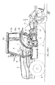
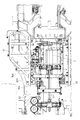
図1は、トラクタを示すものであり、この走行車体1前部のボンネット2内部にエンジンEを搭載し、このエンジンEの回転動力をミッションケース3内の変速装置に伝え、この変速装置で減速された回転動力を前輪4及び後輪5とに伝えるようにしている。エンジンEの後方に前輪4,4を操舵するステアリングハンドル6が装備され、更に、その後方には運転席7が設置されている。ミッションケース3の後上部には油圧シリンダケース8が搭載され、このシリンダケース8の左右両側には、油圧昇降機構の一部を構成するリフトアーム9が回動自在に取り付けられている。リフトアーム9は昇降用油圧シリンダ10の伸縮作動により上下動する。車体後部には、トップリンク11と左右のロアーリンク12からなる3点リンク機構を設け、同リンク機構にロータリ作業機Rを装着している。
An embodiment of the present invention will be described with reference to the drawings.
FIG. 1 shows a tractor. An engine E is mounted inside a
前記ボンネット2は、コの字状のボンネット支柱13、アーチ型補強部材14a,14b、これらを結ぶ前後方向の縦補強部材15等によって支持され、後端部の横軸芯Pを支点として前端側が上下に揺動開閉する構成としている。特に、前記ボンネット支柱13は、エンジンEを搭載する車体側から突設するコの字型支柱13aと、ボンネットの開閉支点部Pを保有するコの字型ブラケット13bとからなり、これらコの字型形状を合わせて取付保持することで、組み立てが容易に行える。
The
前記ハンドル6や運転席7等は、キャビン16によって被覆されている。キャビンは、例えば防振ゴム等の弾性部材を介して機体に固定されてあり、機体の振動がキャビンに伝達されにくくしている。
The handle 6 and the driver's
また、キャビン16は、フロア17と、フロア17左右前部に立設した前支柱16aと、左右フェンダー18中間部に立設する後支柱16bと、これら支柱上端同士を接続する上フレーム16cとによって一体化した構成としている。
The
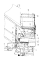
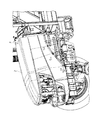
ミッションケース3の左右両側には樹脂材より成型された燃料タンク20L,20Rを配置し、前方側のタンク支持枠(パイプ)21と後方側のタンクフレーム(平板)22とによって支持した構成としている。左右の燃料タンク20L,20Rは、両タンクの上部を接続ホース23を介してブリーザ凸部24,24に接続してあり、そして、そのブリーザホース25は、その途中部をキャビン16の下部フレーム19に支持ステー26を介して止着し、且つ、外気に通じるブリーザホースの開口端部25aは、該タンクより上方に高い位置において前記ボンネット支柱13にスチールパイプ27を介して装着している。また、左右タンクの下部(底部)側は、中間部から左右方向外側上方に向けて傾斜する接続管28によって接続してあり、この接続管28の左右傾斜部内には、上り傾斜方向には流通を許容し、下り傾斜方向には逆流を阻止する逆止弁29,29を内装している。また、接続管28の中間部にはドレンパイプ30を内嵌して設け、ドレンパイプの底壁にドレン孔31とこれを塞ぐドレンプラグ32を設けている。なお、ドレンパイプ30の一端部に逆止弁を一体で設置するように構成しておくと、組み立てが容易にでき、方向を間違えることなく組み立てが可能で、安価に実施することができる。
33は給油口34を開閉するキャップで、左側タンク20Lの前側に設けてあり、しかも、このキャップ位置はキャビン16より前側位置となるよう配置している。また、該タンク20Lの給油口34より後方部分をタンク上面より下方に凹入する凹入部35形状とし、ブリーザ凸部24を給油口34より高くすることで、タンク容量を最大限に大きくとることができるようにしている。
左右タンク20L,20Rの後方部は、ミッションケース3から取付ボルト36を介して支持したフレーム37の端部に固定のタンクフレーム22に支持している。また、左右タンクの前方部は、キャビン16下方のマウントブラケット38に支持部材39を介して固定した丸パイプからなるタンク支持枠21に支持する構成としている。そして、この左右タンク20L,20Rは、数個のスチールバンド40,40によってタンク支持枠21及びタンクフレーム22に取付ステー41、螺子具42、締付具43を介して締め付け固定するようになっている。前記接続ホース23は、左右横方向の丸パイプからなるキャビンフレーム44に沿わせて取り付けてあり、ブリーザホース25は、前記したようにキャビンの下部フレーム19に止着している。46はタンクガード(カバー)、47は燃料フィルターを示す。
The rear portions of the left and
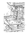
次に図12、図13に示す実施例について説明すると、トラクタキャビンのフロア下方に設置され、ミッションケース3の左右に配置された燃料タンク20L,20Rにおいて、ミッションケースの側面に設置されたPTOクラッチ用バルブ50a、油圧ポンプ50b、4駆2駆切替用バルブ50c等の油圧機器50の形状に合わせてタンクの側面を凹凸形状とし、両者間に所定の空間を施した構成としている。従って、かかる構成によれば、油圧機器のメンテナンスを燃料タンクを外すことなく行え、ミッションケースからの熱気を燃料タンクに伝えることなく所定空間から容易に逃がすことができる。
Next, the embodiment shown in FIGS. 12 and 13 will be described. In the
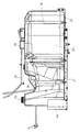
また、図14に示すように、トラクタのエンジン周辺を囲むボンネット2が後端部の横軸芯Pを支点として前端側が上下に揺動開閉する構成のものにおいて、そのボンネット後方下部のサイドカバー51が前端の上下方向の取付ピン52を支点としてワンタッチで揺動開閉する構成とし、少なくとも、片側を開放することによりエンジンのメンテナンスが容易に行えるようにしている。特に、このカバー51を開けると、エンジンオイル用の給油口53があり、一部を開放するだけで簡単に給油することができる。
Further, as shown in FIG. 14, the
図15に示すように、ラジエータ54やバッテリ55などのエンジン補器を載せるよう構成されたアクスルブラケット56において、ボンネットの形状に合わせたプレート57(フロントプレート57F、サイドプレート57L,57R)をアクスルブラケット周囲の枠上に設けることにより、ボンネットの形状によって自由にスペーサプレートの形状を変更することで対応でき、安価に構成できる。また、アクスルブラケットも軽量化できて安価に実施することができる。
As shown in FIG. 15, in an
前記図10において、通常燃料ポンプによってエンジン側に供給される供給燃料管の一端は左右タンクいずれかの底部に接続されるが、符号60で示すように、左右接続ドレンパイプ30の中間部にその一端を接続する構成とすることもできる。このように構成すると、機体が左右に傾いても最下端あたりで燃料を供給できるため、残量が少なくてもエアの吸い込みもなく良好にエンジン側に供給させることができる。 In FIG. 10, one end of the supply fuel pipe supplied to the engine side by the normal fuel pump is connected to the bottom of either the left or right tank. It can also be set as the structure which connects one end. With this configuration, fuel can be supplied near the lowermost end even if the aircraft is tilted to the left and right, so that it can be satisfactorily supplied to the engine without inhaling air even if the remaining amount is small.
2 ボンネット
13 ボンネット支柱
16 キャビン
19 下部フレーム
20 燃料タンク
21 タンク支持枠
22 タンクフレーム
23 接続ホース
24 ブリーザ凸部
25 ブリーザホース
25a ブリーザホースの開口端部
27 スチールパイプ
28 接続管
30 ドレンパイプ
31 ドレン孔
32 ドレンプラグ
33 キャップ
34 給油口
37 フレーム
38 マウントブラケット
39 支持部材
40 スチールバンド
51 サイドカバー
52 取付ピン
53 給油口
P ボンネット後端部の横軸芯
2 bonnet
13
23 connection hose
24 breather convex
25 breather hose
Open end of 25a breather hose
27
51 side cover
52 mounting pins
53 Refueling port
Horizontal axis at the rear end of P bonnet
Claims (2)
左右の燃料タンク(20L),(20R)は、両タンクの上部を接続ホース(23)を介してブリーザ凸部(24),(24)に接続し、ブリーザホース(25)をブリーザ凸部(24)に接続し、且つ、外気に通じるブリーザホース(25)の開口端部(25a)は、該左右の燃料タンク(20L),(20R)より上方に高い位置においてボンネット(2)を支持するボンネット支柱(13)にスチールパイプ(27)を介して装着するように構成したトラクタ。 The fuel tanks (20L) and (20R) disposed on the left and right sides of the transmission case (3) are supported by the tank frame (22) fixed to the end of the frame (37) supported from the transmission case, The front part is supported by the tank support frame (21) so as to be fixed to the mount bracket (38) below the cabin (16), and the lower side of both tanks (20L), (20R) is connected by the connecting pipe (28), A fuel filler port (34) is provided on the front side of one of the fuel tanks (20L) so that the cap (33) is positioned on the front side of the cabin (16),
The left and right fuel tanks (20L), (20R) are connected to the breather projections (24), (24) via the connection hoses (23) at the tops of both tanks, and the breather hoses (25) are connected to the breather projections ( 24) and the open end (25a) of the breather hose (25) communicating with the outside air supports the bonnet (2) at a position higher than the left and right fuel tanks (20L), (20R). A tractor configured to be attached to a bonnet support (13) via a steel pipe (27).
Priority Applications (1)
| Application Number | Priority Date | Filing Date | Title |
|---|---|---|---|
| JP2006179834A JP4857955B2 (en) | 2006-06-29 | 2006-06-29 | Tractor |
Applications Claiming Priority (1)
| Application Number | Priority Date | Filing Date | Title |
|---|---|---|---|
| JP2006179834A JP4857955B2 (en) | 2006-06-29 | 2006-06-29 | Tractor |
Publications (3)
| Publication Number | Publication Date |
|---|---|
| JP2008006981A JP2008006981A (en) | 2008-01-17 |
| JP2008006981A5 JP2008006981A5 (en) | 2009-03-19 |
| JP4857955B2 true JP4857955B2 (en) | 2012-01-18 |
Family
ID=39065564
Family Applications (1)
| Application Number | Title | Priority Date | Filing Date |
|---|---|---|---|
| JP2006179834A Expired - Fee Related JP4857955B2 (en) | 2006-06-29 | 2006-06-29 | Tractor |
Country Status (1)
| Country | Link |
|---|---|
| JP (1) | JP4857955B2 (en) |
Families Citing this family (7)
| Publication number | Priority date | Publication date | Assignee | Title |
|---|---|---|---|---|
| JP5154458B2 (en) * | 2009-01-14 | 2013-02-27 | ヤンマー株式会社 | Work vehicle |
| JP5243297B2 (en) * | 2009-02-23 | 2013-07-24 | ヤンマー株式会社 | Work vehicle |
| JP6083358B2 (en) * | 2013-08-29 | 2017-02-22 | 井関農機株式会社 | vehicle |
| JP6305307B2 (en) * | 2014-10-16 | 2018-04-04 | ヤンマー株式会社 | Work vehicle |
| JP6692138B2 (en) * | 2015-09-30 | 2020-05-13 | 三菱マヒンドラ農機株式会社 | Work vehicle |
| US10538179B2 (en) | 2015-12-11 | 2020-01-21 | Kubota Corporation | Work vehicle |
| JP6541568B2 (en) * | 2015-12-24 | 2019-07-10 | 株式会社クボタ | Work vehicle equipped with an engine |
Family Cites Families (7)
| Publication number | Priority date | Publication date | Assignee | Title |
|---|---|---|---|---|
| JPS5737019A (en) * | 1980-08-09 | 1982-03-01 | Tomotaro Sato | All-wheel drive autotricycle |
| BG39893A1 (en) * | 1984-05-07 | 1986-09-15 | Ljuckanov | Thermoinsulating refractory mass |
| FR2614079B1 (en) * | 1987-04-14 | 1992-04-10 | Valeo | STRAIGHT MEASUREMENT OF TORSIONAL DAMPING DEVICE |
| JPH0699747A (en) * | 1992-09-22 | 1994-04-12 | Iseki & Co Ltd | Fuel tank mounting device for tractor |
| JP3503733B2 (en) * | 1997-09-12 | 2004-03-08 | 日野自動車株式会社 | Bus fuel tank support device |
| JP4285882B2 (en) * | 2000-04-10 | 2009-06-24 | 三菱農機株式会社 | Work vehicle fuel tank |
| JP2003291668A (en) * | 2002-04-01 | 2003-10-15 | Iseki & Co Ltd | Work vehicle |
-
2006
- 2006-06-29 JP JP2006179834A patent/JP4857955B2/en not_active Expired - Fee Related
Also Published As
| Publication number | Publication date |
|---|---|
| JP2008006981A (en) | 2008-01-17 |
Similar Documents
| Publication | Publication Date | Title |
|---|---|---|
| JP4857955B2 (en) | Tractor | |
| US9828744B2 (en) | Working machine | |
| JP2008006981A5 (en) | ||
| JP6230515B2 (en) | Work vehicle | |
| JP5009933B2 (en) | Wheel loader | |
| JP5985918B2 (en) | Work vehicle body structure | |
| EP3189997B1 (en) | Work vehicle having engine mounted thereto | |
| JP6066808B2 (en) | Work vehicle | |
| WO2006123756A1 (en) | Traveling vehicle | |
| JP6647153B2 (en) | Work vehicle | |
| JP6083358B2 (en) | vehicle | |
| JP2009006811A (en) | Walking type working machine | |
| JP2005178490A (en) | Tractor | |
| JP6897634B2 (en) | Work vehicle | |
| JP4150115B2 (en) | Tractor | |
| JP3606625B2 (en) | Rice transplanter | |
| JP6217837B2 (en) | Tractor | |
| JP4729827B2 (en) | Tractor fuel tank mounting device | |
| EP2913215B1 (en) | Working vehicle | |
| JP5725805B2 (en) | Passenger work vehicle | |
| JP4618402B2 (en) | Traveling body | |
| JP4292021B2 (en) | Tractor fuel tank | |
| JP6079107B2 (en) | Self-propelled control machine | |
| JP4352021B2 (en) | Traveling vehicle | |
| JP7088147B2 (en) | Work vehicle |
Legal Events
| Date | Code | Title | Description |
|---|---|---|---|
| A521 | Written amendment |
Free format text: JAPANESE INTERMEDIATE CODE: A523 Effective date: 20090129 |
|
| A621 | Written request for application examination |
Free format text: JAPANESE INTERMEDIATE CODE: A621 Effective date: 20090330 |
|
| A977 | Report on retrieval |
Free format text: JAPANESE INTERMEDIATE CODE: A971007 Effective date: 20110609 |
|
| A131 | Notification of reasons for refusal |
Free format text: JAPANESE INTERMEDIATE CODE: A131 Effective date: 20110614 |
|
| A521 | Written amendment |
Free format text: JAPANESE INTERMEDIATE CODE: A523 Effective date: 20110808 |
|
| TRDD | Decision of grant or rejection written | ||
| A01 | Written decision to grant a patent or to grant a registration (utility model) |
Free format text: JAPANESE INTERMEDIATE CODE: A01 Effective date: 20111004 |
|
| A01 | Written decision to grant a patent or to grant a registration (utility model) |
Free format text: JAPANESE INTERMEDIATE CODE: A01 |
|
| A61 | First payment of annual fees (during grant procedure) |
Free format text: JAPANESE INTERMEDIATE CODE: A61 Effective date: 20111017 |
|
| R150 | Certificate of patent or registration of utility model |
Ref document number: 4857955 Country of ref document: JP Free format text: JAPANESE INTERMEDIATE CODE: R150 Free format text: JAPANESE INTERMEDIATE CODE: R150 |
|
| FPAY | Renewal fee payment (event date is renewal date of database) |
Free format text: PAYMENT UNTIL: 20141111 Year of fee payment: 3 |
|
| LAPS | Cancellation because of no payment of annual fees |