JP6541568B2 - Work vehicle equipped with an engine - Google Patents
Work vehicle equipped with an engine Download PDFInfo
- Publication number
- JP6541568B2 JP6541568B2 JP2015252593A JP2015252593A JP6541568B2 JP 6541568 B2 JP6541568 B2 JP 6541568B2 JP 2015252593 A JP2015252593 A JP 2015252593A JP 2015252593 A JP2015252593 A JP 2015252593A JP 6541568 B2 JP6541568 B2 JP 6541568B2
- Authority
- JP
- Japan
- Prior art keywords
- fuel tank
- fuel
- passage
- engine
- return
- Prior art date
- Legal status (The legal status is an assumption and is not a legal conclusion. Google has not performed a legal analysis and makes no representation as to the accuracy of the status listed.)
- Active
Links
Images

Landscapes
- Cooling, Air Intake And Gas Exhaust, And Fuel Tank Arrangements In Propulsion Units (AREA)
Description
本発明は、複数の燃料タンクから燃料が供給されるエンジンを搭載した作業車両に関する。 The present invention relates to a work vehicle equipped with an engine supplied with fuel from a plurality of fuel tanks.
特許文献1に開示された農用トラクタにおける燃料タンクシステムでは、右側燃料タンクと左側燃料タンクの上部同士が空気流通パイプで連通されるとともに右側燃料タンクと左側燃料タンクの底部同士が燃料取出パイプで連結され、燃料取出パイプの中央からポンプ吸引パイプが分岐している。ポンプ吸引パイプには燃料ポンプが設けられており、燃料供給ポンプからエンジンに燃料が供給される。 In the fuel tank system in the agricultural tractor disclosed in Patent Document 1, the upper portions of the right fuel tank and the left fuel tank are communicated with each other by the air flow pipe, and the bottom portions of the right fuel tank and the left fuel tank are connected by the fuel outlet pipe The pump suction pipe is branched from the center of the fuel extraction pipe. The pump suction pipe is provided with a fuel pump, and fuel is supplied from the fuel supply pump to the engine.
複数の燃料タンクを搭載した場合、作業車両における重量バランスを考慮して、それぞれの燃料タンクにおける残留燃料が同じように減ることが要望される。そのために、例えば、燃料切り替えコックなどを設けて、使用する燃料タンクを随時選択することで、それぞれの残留燃料ができるだけ同じようにすることは可能である。しかしながら、燃料切り替えコックを随時操作することは、運転者に負担を与えることになる。このことから、燃料切り替えコックを省きながらも、各燃料タンクの内圧を均等に保つことで、複数の燃料タンクから均等に燃料がエンジンに供給される燃料システムを構築し、複数の燃料タンクの残留燃料ができるだけ同じとなるような技術が要望されている。 When a plurality of fuel tanks are mounted, it is desired that the residual fuel in each fuel tank be similarly reduced in consideration of the weight balance in the work vehicle. For that purpose, for example, by providing a fuel switching cock and selecting a fuel tank to be used as needed, it is possible to make each residual fuel as similar as possible. However, operating the fuel switching cock at any time places a burden on the driver. From this, while eliminating the fuel switching cock, by maintaining the internal pressure of each fuel tank equally, a fuel system is constructed in which fuel is supplied to the engine equally from a plurality of fuel tanks, and a plurality of fuel tanks remain There is a demand for technology that makes the fuel as similar as possible.
本発明による、エンジンを搭載した作業車両は、運転座席と、前記運転座席よりも後側に配置されるロプス装置と、前記運転座席よりも後側に配置され、前記エンジンを覆うボンネットと、第1燃料タンクと、第2燃料タンクと、前記第1燃料タンクと合流部とをつなぐ第1燃料供給路、前記第2燃料タンクと前記合流部とをつなぐ第2燃料供給路、及び前記合流部と前記エンジンとをつなぐ共通供給路からなる燃料供給路と、前記共通供給路に設けられ前記第1燃料タンク及び前記第2燃料タンクからの燃料を前記エンジンに供給する燃料ポンプと、前記第1燃料供給路に介装されるとともに燃料タンク側圧力と合流部側圧力との差圧に応じて開弁する第1チェックバルブと、前記第2燃料供給路に介装されるとともに燃料タンク側圧力と合流部側圧力との差圧に応じて開弁する第2チェックバルブと、前記第1燃料タンクの頂部空間と前記第2燃料タンクの頂部空間とを連通する連通流路とを備え、前記第1燃料タンクと前記第2燃料タンクとは前記運転座席の右側と左側とに離れて配置されており、前記連通流路は、前記第1燃料タンクの上面から上方向に延びる第1縦流路部と、前記第2燃料タンクの上面から上方向に延びる第2縦流路部と、前記第1縦流路部の頂部から車体側面視で車体前方向きに延びる第1連結流路部と、前記第2縦流路部の頂部から車体側面視で車体前方向きに延びる第2連結流路部と、前記第1連結流路部の車体前方側端部と前記第2連結流路部の車体前方側端部とに接続する横断流路部とを有し、前記第1縦流路部及び前記第2縦流路部は、車体側面視で前記ロプス装置と重複するように配置され、かつ、前記横断流路部は、車体側面視で前記ボンネットの前壁と前記運転座席との間に配置されている。
また、前記第1燃料タンクは、前記第1燃料タンクの上面から上方向に延びる第1給油部を有し、前記第2燃料タンクは、前記第2燃料タンクの上面から上方向に延びる第2給油部を有し、前記第1縦流路部の高さは、前記第1給油部の高さと略同じ又はそれよりも低く構成され、かつ、前記第2縦流路部の高さは、前記第2給油部の高さと略同じ又はそれよりも低く構成されていることが好ましい。
A work vehicle equipped with an engine according to the present invention includes a driver's seat, a lops device disposed behind the driver's seat, a bonnet disposed behind the driver's seat and covering the engine, 1 fuel tank, second fuel tank, first fuel supply passage connecting the first fuel tank and the junction, second fuel supply passage connecting the second fuel tank and the junction, and the junction A fuel supply path comprising a common supply path connecting the engine and the fuel pump; a fuel pump provided in the common supply path for supplying fuel from the first fuel tank and the second fuel tank to the engine; A first check valve which is interposed in the fuel supply passage and which opens in response to a differential pressure between the fuel tank side pressure and the merging portion side pressure, and is interposed in the second fuel supply passage and also is connected with the fuel tank side pressure When Comprising a second check valve which opens in response to differential pressure between the flow portion side pressure, and a communication passage for communicating the head space of the second fuel tank and the head space of the first fuel tank, said first The first fuel tank and the second fuel tank are spaced apart on the right and left sides of the driver's seat, and the communication channel is a first vertical channel extending upward from the top surface of the first fuel tank A second vertical flow passage extending upward from the upper surface of the second fuel tank, and a first connection flow passage extending from the top of the first vertical flow passage forward in the vehicle body in a side view of the vehicle; A second connection channel extending from the top of the second vertical channel forward in a vehicle body side view in a side view of the vehicle, a vehicle front end of the first connection channel and a vehicle body of the second connection channel And a transverse flow passage portion connected to the front side end portion, wherein the first longitudinal flow passage portion and the second longitudinal flow passage portion It is arranged to overlap the ROPS device as viewed from the side, and the transverse flow passage portion is disposed between the driver's seat and the front wall of the hood when the body is viewed from the side.
The first fuel tank may have a first fueling portion extending upward from the top surface of the first fuel tank, and the second fuel tank may extend upward from the top surface of the second fuel tank. It has a refueling portion, the height of the first vertical flow passage portion is configured to be substantially the same as or lower than the height of the first refueling portion, and the height of the second vertical flow passage portion is It is preferable that the height of the second refueling portion is substantially equal to or less than the height of the second refueling portion.
この構成によれば、ディーゼルエンジンへの燃料供給のため、チェックバルブを介して第1燃料タンクと第2燃料タンクとから燃料が共通の燃料ポンプによって吸引される。その際、燃料供給路にチェックバルブが介在しているので、第1燃料タンクと第2燃料タンクとの間で貯留量の違いから圧力差があれば、圧力の大きな方、つまり貯留量が大きい方の燃料タンクからより多くの燃料が吸引される。したがって、第1燃料タンクと第2燃料タンクとにおける供給圧力の差が、燃料貯留量の差だけを起因とすることが重要である。
例えば、給油部の給油口を閉鎖する給油キャップの精度のばらつきなどで、タンク内圧に差が生じると、一方の燃料タンクからのみ燃料が吸引される可能性がある。このような不都合は、第1燃料タンクの頂部空間と第2燃料タンクの頂部空間とを連通する連通流路によってそれぞれの内圧が平衡化されることで、解消される。これにより、第1燃料タンクと第2燃料タンクとにおける貯留量に差が生じることが回避される。
According to this configuration, the fuel is drawn from the first fuel tank and the second fuel tank by the common fuel pump via the check valve to supply the fuel to the diesel engine. At that time, since the check valve intervenes in the fuel supply passage, if there is a pressure difference due to the difference in storage amount between the first fuel tank and the second fuel tank, the larger pressure, that is, the larger storage amount More fuel is drawn from the other fuel tank. Therefore, it is important that the difference in supply pressure between the first fuel tank and the second fuel tank be caused solely by the difference in the amount of stored fuel.
For example, if there is a difference in the tank internal pressure due to variations in the accuracy of the filler cap that closes the filler port of the filler section, fuel may be drawn from only one of the fuel tanks. Such a problem is solved by the internal flow paths being in communication between the top space of the first fuel tank and the top space of the second fuel tank so that the respective internal pressures are equalized. Thereby, it is avoided that a difference arises in the amount of storage in the 1st fuel tank and the 2nd fuel tank.
連通流路は、燃料の液面の上方空間に開口する必要があり、この条件を満たす場所は給油口を形成している給油部付近である。このため、連通流路の一端が、第1燃料タンクの給油部に隣接する位置で開口し、連通流路の他端が、第2燃料タンクの給油部に隣接する位置で開口することが、好都合である。 The communication channel needs to be opened in the space above the liquid surface of the fuel, and the place satisfying this condition is near the fueling portion forming the fueling port. Therefore, one end of the communication flow passage opens at a position adjacent to the fueling portion of the first fuel tank, and the other end of the communication flow passage opens at a position adjacent to the fueling portion of the second fuel tank. It is convenient.
燃料は重量物であるので、第1燃料タンク及び第2燃料タンクが車両の重量バランスに悪影響を与えないためには、車両の右側と左側に分けて配置することが好ましい。その際、連通流路は他の部材との干渉が少なく、運転者等の動きや他の機器の設置の邪魔にならない場所に配置することが好ましい。このため、本発明の好適な実施形態では、第1燃料タンクと第2燃料タンクとは運転座席の右側と左側とに離れて配置されており、連通流路は前記運転座席の後を通過する。連通流路の保護の観点から、連通流路は、ゴムホースで形成し、このゴムホースを鋼管などの金属パイプで外囲することが好ましい。 Since the fuel is heavy, it is preferable to separately arrange the right and left sides of the vehicle so that the first fuel tank and the second fuel tank do not adversely affect the weight balance of the vehicle. At this time, it is preferable that the communication flow path be disposed in a place where the interference with other members is small and the movement of the driver or the like and the installation of other devices are not disturbed. For this reason, in a preferred embodiment of the present invention, the first fuel tank and the second fuel tank are disposed separately on the right and left sides of the driver's seat, and the communication passage passes behind the driver's seat . From the viewpoint of protection of the communication flow channel, the communication flow channel is preferably formed of a rubber hose, and the rubber hose is preferably enclosed by a metal pipe such as a steel pipe.
エンジンがディーゼルエンジンの場合、燃料ポンプによって供給されてきた燃料の一部を燃料タンクに戻す必要があるので、ディーゼルエンジンから余り燃料を第1燃料タンク及び第2燃料タンクに戻す燃料戻り路が備えられている。その際、第1燃料タンクと第2燃料タンクとにおける貯留量(燃料残量)に大きな差を生じさせないためには、ディーゼルエンジンから第1燃料タンク及び第2燃料タンクに戻される燃料の量もできるだけ等しいことが望ましい。このため、本発明の好適な実施形態の1つでは、燃料戻り路は、エンジンと分岐部とをつなぐ共通戻り路、分岐部と第1燃料タンクとをつなぐ第1燃料戻り路、及び分岐部と前記第2燃料タンクとをつなぐ第2燃料戻り路とからなり、第1燃料タンク内に形成された第1燃料戻り路の戻り口と第2燃料タンク内に形成された第2燃料戻り路の戻り口とが、当該燃料タンクでの同じ高さ(ほぼ同じ高さも含まれる)レベルに設定されている。この構成では、ディーゼルエンジンから戻された燃料は分岐部で分岐し、それぞれの分岐燃料が第1燃料タンクと第2燃料タンクに戻る。そこで、いずれかの燃料タンクの貯留量が増加し、例えば戻り口を塞ぐ用の状態となれば、その燃料戻り路内の圧力が上昇するので、ディーゼルエンジンから戻された燃料は他の燃料タンクに流れ込むことになり、片方の燃料タンクだけが満杯になることが回避される。この実施形態における、両方の戻り口がほぼ同じ高さレベルであるとは、いずれかの燃料タンクだけが満杯になってしまうことが回避されることが保証される高さレベルを意味している。 When the engine is a diesel engine, it is necessary to return part of the fuel supplied by the fuel pump to the fuel tank, so a fuel return path is provided to return the remaining fuel from the diesel engine to the first fuel tank and the second fuel tank. It is done. At this time, in order not to make a large difference in the storage amount (remaining fuel amount) in the first fuel tank and the second fuel tank, the amount of fuel returned from the diesel engine to the first fuel tank and the second fuel tank is also It is desirable to be as equal as possible. Therefore, in one preferred embodiment of the present invention, the fuel return passage includes a common return passage connecting the engine and the branch, a first fuel return passage connecting the branch and the first fuel tank, and a branch And a second fuel return passage connecting the second fuel tank and the second fuel tank, and the second fuel return passage formed in the second fuel tank and the return port of the first fuel return passage formed in the first fuel tank And the same height (including approximately the same height) level in the fuel tank. In this configuration, the fuel returned from the diesel engine branches at the branch, and each branched fuel returns to the first fuel tank and the second fuel tank. Therefore, if the storage amount of one of the fuel tanks is increased, for example, if the state for closing the return port is reached, the pressure in the fuel return passage is increased, so the fuel returned from the diesel engine is the other fuel tank. Flow, and it is avoided that only one fuel tank is full. In this embodiment, having both return ports at approximately the same height level means a height level that is guaranteed to avoid that only one of the fuel tanks is full. .
ディーゼルエンジンから第1燃料タンクと第2燃料タンクとに戻される燃料の比率をできるだけ等しくするためには、前記第1燃料戻り路と前記第2燃料戻り路とにおける燃料の流れ抵抗が実質的に同じであるとよい。例えば、両者の違いが0%から20%以内に収まっていることが好ましい。そのための好適な方策の1つは、前記第1燃料戻り路と前記第2燃料戻り路とは流れ断面積及び流路長さが実質的に同じにすることである。例えば、第1燃料戻り路と第2燃料戻り路における流れ断面積の違い、及び流路長さの違いが、0%から20%以内に収まっていることが好ましい。 In order to make the proportions of fuel returned from the diesel engine to the first fuel tank and the second fuel tank as equal as possible, the flow resistance of fuel in the first fuel return passage and the second fuel return passage is substantially reduced. It should be the same. For example, it is preferable that the difference between the two be within 0% to 20%. One of the preferred measures is that the first fuel return passage and the second fuel return passage have substantially the same flow cross-sectional area and flow passage length. For example, it is preferable that the difference in flow cross section between the first fuel return passage and the second fuel return passage and the difference in flow passage length be within 0% to 20%.
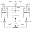
本発明による作業車両の具体的な実施形態を説明する前に、図1を用いて、本発明で採用されている燃料タンクとエンジンとの間の燃料流通の基本的な構成を説明する。この作業車両に搭載されているエンジン3は、左右一対の第1燃料タンク61と第2燃料タンク62とから燃料供給を受ける。第1燃料タンク61と第2燃料タンク62とは、実質的にはほぼ同一の形状を有するが、同一である必要はない。第1燃料タンク61及び第2燃料タンク62とエンジン3の燃料供給口67Aとの間は、一般には燃料ホースで構成される燃料供給路67でつながれている。燃料供給路67は、第1燃料タンク61と合流部65とを接続する第1燃料供給路671と、第2燃料タンク62と合流部65とを接続する第2燃料供給路672と、合流部65とエンジン3の燃料供給口67Aとを接続する共通供給路670とからなる。第1燃料供給路671には第1チェックバルブ63が介装されており、第2燃料供給路672には第2チェックバルブ64が介装されている。共通供給路670には、燃料ポンプ60が介装されている。第1チェックバルブ63及び第2チェックバルブ64は、燃料タンク側圧力と前記合流部側圧力との差圧に応じて開弁する。つまり、燃料ポンプ60の駆動により合流部65に負圧が生じると、第1チェックバルブ63及び第2チェックバルブ64は開弁し、第1燃料タンク61及び第2燃料タンク62から燃料が共通供給路670に流れ込む。
Before describing a specific embodiment of a work vehicle according to the present invention, FIG. 1 will be used to explain the basic configuration of fuel flow between a fuel tank and an engine adopted in the present invention. The
燃料ポンプ60が駆動すると、燃料ポンプ60の吸引力によって、第1燃料供給路671の合流部65と第1チェックバルブ63との間の圧力が、第1チェックバルブ63と第1燃料タンク61との間の圧力より低くなるので、第1チェックバルブ63が開弁して、第1燃料タンク61からエンジン3への燃料供給が行われる。同様に、第2燃料タンク62からエンジン3への燃料供給も行われる。但し、第1燃料タンク61と第2燃料タンク62のどちらか一方において燃料の貯留量が大きい場合、これに該当する側のチェックバルブにおける圧力差が大きくなり、その開弁量が大きくなる。その結果、燃料の貯留量が大きい方の燃料タンクから主に燃料が燃料ポンプ60に吸い込まれることになる。つまり、第1燃料タンク61と第2燃料タンク62とに貯留している燃料の液圧差によって、第1燃料タンク61と第2燃料タンク62との燃料貯留量の平衡化が行われる。
When the
第1燃料タンク61及び第2燃料タンク62の天井面には給油キャップ90で閉鎖される給油口91を有する給油部9が形成されている。給油キャップ90の個体差や締め具合に起因して、エンジン3への燃料供給にともなって、第1燃料タンク61及び第2燃料タンク62の内圧に差が生じると、燃料の液圧に影響を及ぼし、燃料の液圧差による燃料貯留量の平衡化ができなくなる。このため、第1燃料タンク61の頂部空間S1と第2燃料タンク62の頂部空間S2とを連通する連通流路70が備えられている。連通流路の70一端は、第1燃料タンク61の給油部9に隣接する位置で開口しており、連通流路70の他端は、第2燃料タンク62の給油部9に隣接する位置で開口している。これにより、第1燃料タンク61と第2燃料タンク62との内圧は実質的に同じに保たれる。
On the ceiling surfaces of the
図1の例では、エンジン3としてディーゼルエンジンが採用されているので、第1燃料タンク61及び第2燃料タンク62とエンジン3の燃料戻し口68Aとの間は、一般には燃料ホースで構成される燃料戻り路68でつながれている。燃料戻り路68は、エンジン3の燃料戻し口68Aと分岐部66とを接続する共通戻り路680と、分岐部66と第1燃料タンク61の戻り口68aとを接続する第1燃料戻り路681と、分岐部66と第2燃料タンク62の戻り口68aとを接続する第2燃料戻り路682とからなる。なお、第1燃料タンク61内に形成された戻り口68aと第2燃料タンク62内に形成された戻り口68aとが各燃料タンクにおける高さレベルはほぼ同一である。第1燃料戻り路681と第2燃料戻り路682とにおける燃料の流れ抵抗が実質的に同じにするため、第1燃料戻り路681と第2燃料戻り路682は実質的に同じ流れ断面積及び流路長さを有する。
したがって、例えば、第1燃料タンク61の方にばから戻り燃料が流れ込んで、第1燃料タンク61の戻り口68aまで燃料が達した場合、第1燃料戻り路681の圧力が上昇する。これにより、分岐部66において、エンジン3から戻された燃料のほとんどが第2燃料タンク62の方に流れ込む。
In the example of FIG. 1, a diesel engine is adopted as the
Therefore, for example, when the return fuel flows from the side of the
なお、上述したような戻り燃料の調節は、第1燃料戻り路681の戻り口68aと前記第2燃料戻り路682の戻り口68aとに燃料液面が一定値を超えると閉鎖するフロート弁69を設けることで、さらに確実なものとなる。
The return fuel adjustment as described above is a
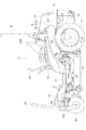
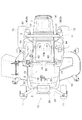
次に、図面を用いて、本発明による作業車両の具体的な実施形態の1つを説明する。この作業車両は、作業装置としてモーアユニット13を装備した乗用草刈機である。図2は、乗用草刈機の側面図であり、図3は平面図である。この乗用草刈機は、ゼロターンモーアとも称されるもので、左右一対の前輪11と、独立して回転駆動される駆動車輪としての左右一対の後輪12とによって対地支持された車体10を備えている。車体10は、ベース部材として車体フレーム2を有しており、前輪11と後輪12との間で、モーアユニット13がリンク機構14を介して車体フレーム2から吊り下げられている。車体10の車体前後方向中央領域に運転部5が配置されている。運転部5の後部にはロプス装置6が設けられている。車体10の後端領域にはディーゼルエンジンであるエンジン3が配置されている。エンジン3の前方にはラジエータ31などのエンジン補機が配置されており、エンジン3及びエンジン補機は上方からボンネット30によって覆われている。車体10の運転部5領域には座席支持体52が形成されており、座席支持体52の上面には運転座席53が設けられている。さらに座席支持体52の左右側面にはフェンダ54が形成されている。運転座席53の前方にステップ51が敷設されている。左側のフェンダ54の下方には、後輪12の周面に沿うように、第1燃料タンク61が配置され、右側のフェンダ54の下方には、後輪12の周面に沿うように、第2燃料タンク62が配置されている。
第1燃料タンク61と第2燃料タンク62とは、実質的には同じ形状寸法を有し、車体前後方向で運転座席53の側方からロプス装置6を超える後方に延びている。第1燃料タンク61及び第2燃料タンク62のロプス装置6を超えた後部分の上面部に、給油部9が設けられている。給油部9は、上面部からほぼ垂直に突き出している給油筒610と給油筒610の給油口を覆う給油キャップ90とからなる。
Next, one of the specific embodiments of the work vehicle according to the present invention will be described using the drawings. This work vehicle is a riding mower equipped with the
The
第1燃料タンク61及び第2燃料タンク62を含む燃料システムは、図1を用いて説明した基本構成を採用している。第1燃料タンク61と第2燃料タンク62とを連通する連通流路70はゴムホースを金属パイプ(例えば鋼管)で外囲した連通管として構成されており、運転座席53のシートバック53bとボンネット30の前壁との間に敷設されている。
The fuel system including the
エンジン3の前側にはトランスミッション4が配置されている。トランスミッション4には、左右一対の後車軸伝動部41が含まれておいる。左右の後車軸伝動部41にはそれぞれ、独立して操作可能な静油圧式変速装置(以下HST42と略称する)が無段変速機構の一例として内装されている。HST42は、エンジン動力を正転(前進)状態及び逆転(後進)状態で、低速から高速まで無段階に変更して、それぞれの後輪12に伝達することができる。これにより、左右の後輪12の両方が同じまたはほぼ同じ速度で前進方向に駆動することで直進前進が作り出され、左右の後輪12が同じまたはほぼ同じ速度で後進方向に駆動することで直進後進が作り出される。さらに、左右の後輪12の速度を互いに異ならせることで、車体10を任意の方向に旋回移動させることができ、例えば、左右の後輪12のいずれか一方を零速に近い低速にさせ、他方の後輪12を高速で前進側あるいは後進側に操作することで小回り旋回させることができる。さらに、左右の後輪12を互いに逆方向に駆動することで、車体10を左右の後輪12のほぼ中央部を旋回中心としてスピンターンさせることもできる。左右一対の前輪11は、キャスタ輪に構成されて縦軸芯周りで向きを自由に変更することができるから、左右の後輪12駆動による走行方向に応じて向きが修正されることになる。
A
左右のHST42に対する変速操作は、運転座席53の両側に配置された左右一対の変速レバー49によって行われる。変速レバー49を前後中立位置に保持すると無段変速装置が中立停止状態となり、変速レバー49を中立位置から前方に操作することで前進変速が実現し、後方に操作することで後進変速が実現する。
A shift operation to the left and
図3から明らかなように、車体フレーム2は、左右一対の前フレーム21と左右一対の後フレーム22とからなり、左右の前フレーム21は、複数のクロスビームからなる前クロスビームユニット26によって連結されている。左右の後フレーム22も同様に、複数のクロスビームからなる後クロスビームユニットによって連結されているが、後クロスビームユニットの図示は省略されている。後フレーム22の後端領域に、エンジンマウント領域が形成されている。
As apparent from FIG. 3, the
車体10の前端に位置する前クロスビームユニット26には車体横断方向に延びる前輪支持アーム28が設けられている。前輪支持アーム28の中央に、逆U字状のフロントガード29が立設している。前輪支持アーム28の両端に、キャスタブラケット110を介して前輪11が取り付けられている。
A front
図4は、この草刈機の燃料流通系統図である。この草刈機の燃料流通には、図1を用いて説明した原理が流用されている。構造的な特徴は、第1燃料タンク61の底面と第2燃料タンク62の底面とはエンジン3のクランク軸3aより上方に位置し、第1燃料供給路671は第1燃料タンク61の底面で、第2燃料供給路672は第2燃料タンク62の底面で接続していることである。また、第1燃料タンク61と第2燃料タンク62とが連通流路70によって連通されている。さらに、第1燃料戻り路681は第1燃料タンク61の上面で、第2燃料戻り路682は第2燃料タンク62の上面で接続している。また、第1燃料タンク61と第1チェックバルブ63との間、及び第1燃料タンク61と第1チェックバルブ63との間には、フィルタ6aが介装されている。
FIG. 4 is a fuel flow system diagram of this mowing machine. The principle described with reference to FIG. 1 is diverted to the fuel flow of the mower. The structural feature is that the bottom of the
上述したように、第1燃料タンク61の頂部空間S1と第2燃料タンク62の頂部空間S2とを、その主要部分が実質的に水平に延びる連通流路70で連通することで、それぞれのタンク内圧が均衡化される。ただし、多重安全性を考慮する場合には、給油キャップ90に、タンク内圧を大気圧に保持する構造を採用してもよい。例えば、給油キャップ90と給油筒610との間に、空気を通過させるが燃料を通過させないフィルタ膜を設けることで、第1燃料タンク61と第2燃料タンク62の内圧は常時大気圧に保たれる。
As described above, by connecting the top space S1 of the
〔別実施の形態〕
(1)上述した実施形態では、エンジン3が車体10の後部に配置されていたが、エンジン3が車体10の前部に配置され、トランスミッション4がエンジン3の後方に配置されてもよい。
(2)上述した実施形態では、モーアユニット13が前輪11と後輪12との間に配置されるミッドマウント式が採用されていたが、モーアユニット13が前輪11の前に配置されるフロントマウント式の採用も可能である。
(3)上述した実施形態では、前輪11がキャスタ輪で構成されたが、ステアリングホイールによって操作される操舵輪で構成してもよい。その際には、差動機構によって分岐される同一の変速装置からの出力を左右の後輪12が差動機構を介して受けることになる。
(4)上述した実施形態では、作業装置としてモーアユニット13を搭載した作業車両、つまり乗用草刈機が取り上げられた。これに代えて、作業装置として、噴霧装置、除雪装置、植付装置、収穫装置などを搭載することも可能である。
[Another embodiment]
(1) Although the
(2) In the embodiment described above, the mid-mount type in which the
(3) In the embodiment described above, the
(4) In the embodiment described above, the work vehicle on which the
本発明は、エンジンと複数の燃料タンクとを備えた作業車両に適用可能である。 The present invention is applicable to a work vehicle provided with an engine and a plurality of fuel tanks.
3 :エンジン
53 :運転座席
6a :フィルタ
60 :燃料ポンプ
61 :第1燃料タンク
62 :第2燃料タンク
63 :第1チェックバルブ
64 :第2チェックバルブ
65 :合流部
66 :分岐部
67 :燃料供給路
67A :燃料供給口
670 :共通供給路
671 :第1燃料供給路
672 :第2燃料供給路
68 :燃料戻り路
68A :燃料戻し口
68a :戻り口
680 :共通戻り路
681 :第1燃料戻り路
682 :第2燃料戻り路
70 :連通流路
9 :給油部
S1 :頂部空間
S2 :頂部空間
3: Engine 53:
Claims (7)
運転座席と、
前記運転座席よりも後側に配置されるロプス装置と、
前記運転座席よりも後側に配置され、前記エンジンを覆うボンネットと、
第1燃料タンクと、
第2燃料タンクと、
前記第1燃料タンクと合流部とをつなぐ第1燃料供給路、前記第2燃料タンクと前記合流部とをつなぐ第2燃料供給路、及び前記合流部と前記エンジンとをつなぐ共通供給路からなる燃料供給路と、
前記共通供給路に設けられ前記第1燃料タンク及び前記第2燃料タンクからの燃料を前記エンジンに供給する燃料ポンプと、
前記第1燃料供給路に介装されるとともに燃料タンク側圧力と合流部側圧力との差圧に応じて開弁する第1チェックバルブと、
前記第2燃料供給路に介装されるとともに燃料タンク側圧力と合流部側圧力との差圧に応じて開弁する第2チェックバルブと、
前記第1燃料タンクの頂部空間と前記第2燃料タンクの頂部空間とを連通する連通流路と、が備えられ、
前記第1燃料タンクと前記第2燃料タンクとは前記運転座席の右側と左側とに離れて配置されており、
前記連通流路は、前記第1燃料タンクの上面から上方向に延びる第1縦流路部と、前記第2燃料タンクの上面から上方向に延びる第2縦流路部と、前記第1縦流路部の頂部から車体側面視で車体前方向きに延びる第1連結流路部と、前記第2縦流路部の頂部から車体側面視で車体前方向きに延びる第2連結流路部と、前記第1連結流路部の車体前方側端部と前記第2連結流路部の車体前方側端部とに接続する横断流路部とを有し、
前記第1縦流路部及び前記第2縦流路部は、車体側面視で前記ロプス装置と重複するように配置され、かつ、前記横断流路部は、車体側面視で前記ボンネットの前壁と前記運転座席との間に配置されている作業車両。 It is a working vehicle equipped with an engine,
With the driver's seat,
A lops device disposed behind the driver's seat,
A hood disposed behind the driver's seat and covering the engine;
The first fuel tank,
A second fuel tank,
It comprises a first fuel supply passage connecting the first fuel tank and the junction, a second fuel supply passage connecting the second fuel tank and the junction, and a common supply passage connecting the junction and the engine. A fuel supply path,
A fuel pump provided in the common supply path for supplying fuel from the first fuel tank and the second fuel tank to the engine;
A first check valve interposed in the first fuel supply passage and opening in accordance with a pressure difference between a fuel tank side pressure and a merging portion side pressure;
A second check valve interposed in the second fuel supply passage and opening in accordance with a pressure difference between the fuel tank side pressure and the merging portion side pressure;
A communication passage connecting the top space of the first fuel tank and the top space of the second fuel tank ;
The first fuel tank and the second fuel tank are spaced apart on the right and left sides of the driver's seat,
The communication passage includes a first vertical passage extending upward from the upper surface of the first fuel tank, a second vertical passage extending upward from the upper surface of the second fuel tank, and the first vertical passage. A first connection channel extending from the top of the flow channel toward the front of the vehicle in a side view of the vehicle, and a second connection channel extending from the top of the second vertical channel toward the front of the vehicle in a side view of the vehicle; A transverse flow passage portion connected to a vehicle body front side end portion of the first connection flow passage portion and a vehicle body front side end portion of the second connection flow passage portion;
The first longitudinal flow passage portion and the second longitudinal flow passage portion are disposed so as to overlap with the lops device in a side view of the vehicle body, and the transverse flow passage portion is a front wall of the bonnet in a side view of the vehicle body Work vehicle disposed between the and the driver's seat .
前記第2燃料タンクは、前記第2燃料タンクの上面から上方向に延びる第2給油部を有し、The second fuel tank has a second fueling portion extending upward from the top surface of the second fuel tank,
前記第1縦流路部の高さは、前記第1給油部の高さと略同じ又はそれよりも低く構成され、かつ、前記第2縦流路部の高さは、前記第2給油部の高さと略同じ又はそれよりも低く構成されている請求項1に記載の作業車両。The height of the first vertical flow passage portion is configured to be substantially the same as or lower than the height of the first oil supply portion, and the height of the second vertical flow passage portion is equal to that of the second oil supply portion The work vehicle according to claim 1, wherein the work vehicle is configured to be substantially the same as or lower than the height.
Priority Applications (2)
| Application Number | Priority Date | Filing Date | Title |
|---|---|---|---|
| JP2015252593A JP6541568B2 (en) | 2015-12-24 | 2015-12-24 | Work vehicle equipped with an engine |
| US15/361,674 US10538179B2 (en) | 2015-12-11 | 2016-11-28 | Work vehicle |
Applications Claiming Priority (1)
| Application Number | Priority Date | Filing Date | Title |
|---|---|---|---|
| JP2015252593A JP6541568B2 (en) | 2015-12-24 | 2015-12-24 | Work vehicle equipped with an engine |
Publications (2)
| Publication Number | Publication Date |
|---|---|
| JP2017115727A JP2017115727A (en) | 2017-06-29 |
| JP6541568B2 true JP6541568B2 (en) | 2019-07-10 |
Family
ID=59231926
Family Applications (1)
| Application Number | Title | Priority Date | Filing Date |
|---|---|---|---|
| JP2015252593A Active JP6541568B2 (en) | 2015-12-11 | 2015-12-24 | Work vehicle equipped with an engine |
Country Status (1)
| Country | Link |
|---|---|
| JP (1) | JP6541568B2 (en) |
Families Citing this family (1)
| Publication number | Priority date | Publication date | Assignee | Title |
|---|---|---|---|---|
| JP6897634B2 (en) * | 2018-05-31 | 2021-07-07 | 井関農機株式会社 | Work vehicle |
Family Cites Families (8)
| Publication number | Priority date | Publication date | Assignee | Title |
|---|---|---|---|---|
| JPH0449517U (en) * | 1990-09-04 | 1992-04-27 | ||
| US5186352A (en) * | 1992-05-12 | 1993-02-16 | General Electric Company | Compartmentalized fluid tank |
| JPH0971140A (en) * | 1995-09-07 | 1997-03-18 | Kubota Corp | Combine fuel supply system structure |
| JP2005178490A (en) * | 2003-12-18 | 2005-07-07 | Yanmar Co Ltd | Tractor |
| JP2007309137A (en) * | 2006-05-16 | 2007-11-29 | Yanmar Co Ltd | Traveling working machine |
| JP4857955B2 (en) * | 2006-06-29 | 2012-01-18 | 井関農機株式会社 | Tractor |
| JP2008018913A (en) * | 2006-07-14 | 2008-01-31 | Mitsubishi Agricult Mach Co Ltd | Fuel tank structure of working vehicle |
| JP2014104933A (en) * | 2012-11-29 | 2014-06-09 | Iseki & Co Ltd | Fuel tank arrangement structure of work vehicle |
-
2015
- 2015-12-24 JP JP2015252593A patent/JP6541568B2/en active Active
Also Published As
| Publication number | Publication date |
|---|---|
| JP2017115727A (en) | 2017-06-29 |
Similar Documents
| Publication | Publication Date | Title |
|---|---|---|
| US8172268B2 (en) | Fuel tank for work vehicle | |
| US7647770B2 (en) | Hydraulically driven working vehicle and hydraulic transaxle | |
| JP6382654B2 (en) | Work vehicle equipped with a diesel engine | |
| US6460886B2 (en) | Tractor | |
| US9180776B2 (en) | Work vehicle with engine mounted rearwardly | |
| KR101562698B1 (en) | Body structure of work vehicle | |
| US10538179B2 (en) | Work vehicle | |
| EP2679429B9 (en) | Construction machines and fuel tanks for construction machines | |
| US20140109535A1 (en) | Riding type mower | |
| JP6897634B2 (en) | Work vehicle | |
| JP6541568B2 (en) | Work vehicle equipped with an engine | |
| US8287000B2 (en) | Fluid tank deairation | |
| US9764761B2 (en) | Work vehicle having engine and hydraulic stepless speed changing device | |
| US20240343110A1 (en) | In-Vehicle Fuel Tank Device and Utility Vehicle | |
| US12496900B2 (en) | In-vehicle fuel tank device and utility vehicle | |
| JP2002059750A (en) | Passenger farm work body | |
| JP4736279B2 (en) | Mobile farm machine cooling system | |
| JP2005067327A (en) | Agricultural tractor | |
| Marinello et al. | Analysis and testing of a three-wheeled self-leveling prototype tractor | |
| JP2024094126A (en) | Work vehicle | |
| JP5486888B2 (en) | Ride type rice transplanter | |
| JPH06171556A (en) | Hydraulic operating device such as tractor | |
| JP2008073012A (en) | Hydraulic oil reduction structure for work vehicles | |
| JPH0842669A (en) | Work vehicle | |
| JP2013006566A (en) | Working vehicle |
Legal Events
| Date | Code | Title | Description |
|---|---|---|---|
| A621 | Written request for application examination |
Free format text: JAPANESE INTERMEDIATE CODE: A621 Effective date: 20171222 |
|
| A977 | Report on retrieval |
Free format text: JAPANESE INTERMEDIATE CODE: A971007 Effective date: 20181227 |
|
| A131 | Notification of reasons for refusal |
Free format text: JAPANESE INTERMEDIATE CODE: A131 Effective date: 20190108 |
|
| A521 | Written amendment |
Free format text: JAPANESE INTERMEDIATE CODE: A523 Effective date: 20190304 |
|
| TRDD | Decision of grant or rejection written | ||
| A01 | Written decision to grant a patent or to grant a registration (utility model) |
Free format text: JAPANESE INTERMEDIATE CODE: A01 Effective date: 20190514 |
|
| A61 | First payment of annual fees (during grant procedure) |
Free format text: JAPANESE INTERMEDIATE CODE: A61 Effective date: 20190611 |
|
| R150 | Certificate of patent or registration of utility model |
Ref document number: 6541568 Country of ref document: JP Free format text: JAPANESE INTERMEDIATE CODE: R150 |