JP4856740B2 - 車体前部構造 - Google Patents
車体前部構造 Download PDFInfo
- Publication number
- JP4856740B2 JP4856740B2 JP2009139601A JP2009139601A JP4856740B2 JP 4856740 B2 JP4856740 B2 JP 4856740B2 JP 2009139601 A JP2009139601 A JP 2009139601A JP 2009139601 A JP2009139601 A JP 2009139601A JP 4856740 B2 JP4856740 B2 JP 4856740B2
- Authority
- JP
- Japan
- Prior art keywords
- rigidity member
- low
- vehicle body
- rigidity
- vehicle width
- Prior art date
- Legal status (The legal status is an assumption and is not a legal conclusion. Google has not performed a legal analysis and makes no representation as to the accuracy of the status listed.)
- Expired - Fee Related
Links
Images


Classifications
-
- B—PERFORMING OPERATIONS; TRANSPORTING
- B62—LAND VEHICLES FOR TRAVELLING OTHERWISE THAN ON RAILS
- B62D—MOTOR VEHICLES; TRAILERS
- B62D25/00—Superstructure or monocoque structure sub-units; Parts or details thereof not otherwise provided for
- B62D25/08—Front or rear portions
- B62D25/082—Engine compartments
-
- B—PERFORMING OPERATIONS; TRANSPORTING
- B60—VEHICLES IN GENERAL
- B60D—VEHICLE CONNECTIONS
- B60D1/00—Traction couplings; Hitches; Draw-gear; Towing devices
- B60D1/01—Traction couplings or hitches characterised by their type
- B60D1/04—Hook or hook-and-hasp couplings
-
- B—PERFORMING OPERATIONS; TRANSPORTING
- B60—VEHICLES IN GENERAL
- B60D—VEHICLE CONNECTIONS
- B60D1/00—Traction couplings; Hitches; Draw-gear; Towing devices
- B60D1/48—Traction couplings; Hitches; Draw-gear; Towing devices characterised by the mounting
- B60D1/485—Traction couplings; Hitches; Draw-gear; Towing devices characterised by the mounting mounted by means of transversal members attached to the frame of a vehicle
-
- B—PERFORMING OPERATIONS; TRANSPORTING
- B60—VEHICLES IN GENERAL
- B60D—VEHICLE CONNECTIONS
- B60D1/00—Traction couplings; Hitches; Draw-gear; Towing devices
- B60D1/48—Traction couplings; Hitches; Draw-gear; Towing devices characterised by the mounting
- B60D1/488—Traction couplings; Hitches; Draw-gear; Towing devices characterised by the mounting mounted directly to the chassis of the towing vehicle
-
- B—PERFORMING OPERATIONS; TRANSPORTING
- B60—VEHICLES IN GENERAL
- B60D—VEHICLE CONNECTIONS
- B60D1/00—Traction couplings; Hitches; Draw-gear; Towing devices
- B60D1/48—Traction couplings; Hitches; Draw-gear; Towing devices characterised by the mounting
- B60D1/52—Traction couplings; Hitches; Draw-gear; Towing devices characterised by the mounting removably mounted
-
- B—PERFORMING OPERATIONS; TRANSPORTING
- B60—VEHICLES IN GENERAL
- B60D—VEHICLE CONNECTIONS
- B60D1/00—Traction couplings; Hitches; Draw-gear; Towing devices
- B60D1/48—Traction couplings; Hitches; Draw-gear; Towing devices characterised by the mounting
- B60D1/56—Traction couplings; Hitches; Draw-gear; Towing devices characterised by the mounting securing to the vehicle bumper
- B60D1/565—Traction couplings; Hitches; Draw-gear; Towing devices characterised by the mounting securing to the vehicle bumper having an eyelet
-
- B—PERFORMING OPERATIONS; TRANSPORTING
- B60—VEHICLES IN GENERAL
- B60D—VEHICLE CONNECTIONS
- B60D3/00—Fittings to facilitate pushing
-
- B—PERFORMING OPERATIONS; TRANSPORTING
- B60—VEHICLES IN GENERAL
- B60R—VEHICLES, VEHICLE FITTINGS, OR VEHICLE PARTS, NOT OTHERWISE PROVIDED FOR
- B60R19/00—Wheel guards; Radiator guards, e.g. grilles; Obstruction removers; Fittings damping bouncing force in collisions
- B60R19/02—Bumpers, i.e. impact receiving or absorbing members for protecting vehicles or fending off blows from other vehicles or objects
- B60R19/24—Arrangements for mounting bumpers on vehicles
- B60R19/26—Arrangements for mounting bumpers on vehicles comprising yieldable mounting means
- B60R19/34—Arrangements for mounting bumpers on vehicles comprising yieldable mounting means destroyed upon impact, e.g. one-shot type
-
- B—PERFORMING OPERATIONS; TRANSPORTING
- B62—LAND VEHICLES FOR TRAVELLING OTHERWISE THAN ON RAILS
- B62D—MOTOR VEHICLES; TRAILERS
- B62D21/00—Understructures, i.e. chassis frame on which a vehicle body may be mounted
- B62D21/15—Understructures, i.e. chassis frame on which a vehicle body may be mounted having impact absorbing means, e.g. a frame designed to permanently or temporarily change shape or dimension upon impact with another body
- B62D21/152—Front or rear frames
Landscapes
- Engineering & Computer Science (AREA)
- Mechanical Engineering (AREA)
- Transportation (AREA)
- Chemical & Material Sciences (AREA)
- Combustion & Propulsion (AREA)
- Body Structure For Vehicles (AREA)
Description
この種の車体前部構造は、軽衝突時にエクステンションが潰れてフロントサイドフレームなどの主骨格まで変形させないように設計されるものであった。
このような、車体前部構造として、フロントサイドフレーム前端部とロアフレーム前端部とを互いに連結させ、これらの連結させた前端部にバンパビームを支持したものが知られている(例えば、特許文献1参照。)。
また、バンパビーム自体を軟らかくして衝撃吸収することも考えられるが、左右一方に荷重が入力するオフセット衝突の際には、バンパビームはオフセット荷重を他方に伝達する機能をも有しているため、バンパビームを軟らかくすると、他方に加重伝達することができず、荷重入力側の車体変形が大きくなるという課題も残る。
請求項1に係る発明では、車体前後方向に一対のサイドフレームを延ばし、これらのサイドフレームの互いの前方に高剛性部材を車幅方向に配置した。
高剛性部材が、高剛性部材と比較して低剛性の低剛性部材(エクステンション)を介してサイドフレームの車幅外側に延びるフレーム側フランジに連結され、低剛性部材は、板材にて一体的に形成されるとともに、高剛性部材に結合される断面視コ字状の結合部と、この結合部から連続的に且つ車幅外側に延びる断面視コ字状の横壁と、この横壁から第1の屈曲部を介してサイドフレームに向けて略車体前後方向に延び、前端側が後端側より車幅中央に位置するように傾斜する板状の縦壁と、この縦壁から第2の屈曲部を介して車幅外側に延びるとともに、フレーム側フランジに結合される取付フランジとを備えたので、高剛性部材に、衝突荷重が作用したときには、先ずは、低剛性部材を変形させて衝撃を吸収することができる。例えば、衝突荷重が小さい場合には、低剛性部材のみを変形させて衝撃を吸収することができる。詳細には、低剛性部材の縦壁を変形させるとともに、第1の屈曲部を屈曲させて衝撃エネルギーを吸収することができる。
さらに、低剛性部材が板材にて形成されたので、低剛性部材の潰れ残りが少なく、低剛性部材を十分に変形させることができる。この結果、車体前後方向にスペースの短縮を図ることができる。例えば、サイドフレームの先端と高剛性部材(バンパビーム)の前方に配置するバンパフェイスとの間に十分な空間が確保し難い車両においても、十分な衝撃エネルギー吸収作用を発揮することができる。
この結果、高剛性部材に大きな衝突荷重が作用したときには、高剛性部材は車体後方に後退する。この後退した高剛性部材をサイドフレームで支持することができ、大きな衝突荷重をサイドフレームで受け止めることができる。
さらに、低剛性部材をサイドフレームの車幅外側で結合することで、縦壁を傾斜させた場合にも横壁の必要面積を確保できる。この結果、例えば、横壁に牽引フックの貫通用の孔を開けることができる。
例えば、車種によって必要な耐圧荷重性能が求められる。低剛性部材が、高剛性部材に脱着可能に取付けられたので、低剛性部材の強度・剛性等を調整し、他の車種への流用が可能となる。この結果、車体前部構造の汎用性を拡大することができる。
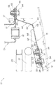
サイドフレーム13は、サイドフレーム13の車幅外方に低剛性部材15が取付けられるフレーム側フランジ17と、牽引フック61(図5参照)の取付用のナット18とを備える。
さらに、横壁42は、車幅外方に向けて幅広に形成される。また、横壁42は変形を防止するように、高剛性に形成される部分である。
また、縦壁44は変形を許容するように、低剛性に形成される部分である。
フレーム側フランジ17は、ボルト64,64がねじ込まれるナット66,66が溶接されている。
高剛性部材14が、高剛性部材14と比較して低剛性の低剛性部材15を介してサイドフレーム13に連結され、低剛性部材15が、板材にて形成されるとともに、高剛性部材14に連結して車幅方向に延びる横壁42と、この横壁42から第1の屈曲部43を介してサイドフレーム13に向けて略車体前後方向に延びる縦壁44とを備えたので、高剛性部材14に、衝突荷重が作用したときには、先ずは、低剛性部材15を変形させて衝撃を吸収することができる。例えば、衝突荷重が小さい場合には、低剛性部材15のみを変形させて衝撃を吸収することができる。詳細には、低剛性部材15の縦壁44を変形させるとともに、第1の屈曲部43を屈曲させて衝撃エネルギーを吸収することができる。
Claims (2)
- 車体前後方向に一対のサイドフレームを延ばし、これらのサイドフレームの互いの前方に高剛性部材を車幅方向に配置した車体前部構造であって、
前記高剛性部材は、高剛性部材と比較して低剛性の低剛性部材を介して前記サイドフレームの車幅外側に延びるフレーム側フランジに連結され、
前記低剛性部材は、板材にて一体的に形成されるとともに、前記高剛性部材に結合される断面視コ字状の結合部と、この結合部から連続的に且つ車幅外側に延びる断面視コ字状の横壁と、この横壁から第1の屈曲部を介して前記サイドフレームに向けて略車体前後方向に延び、前端側が後端側より車幅中央に位置するように傾斜する板状の縦壁と、この縦壁から第2の屈曲部を介して車幅外側に延びるとともに、前記フレーム側フランジに結合される取付フランジとを備え、
前記高剛性部材に衝突荷重が作用したときに前記縦壁を変形させて衝撃を吸収することを特徴とする車体前部構造。 - 前記低剛性部材は、前記高剛性部材に脱着可能に取付けられることを特徴とする請求項1に記載の車体前部構造。
Priority Applications (4)
| Application Number | Priority Date | Filing Date | Title |
|---|---|---|---|
| JP2009139601A JP4856740B2 (ja) | 2009-06-10 | 2009-06-10 | 車体前部構造 |
| CN201010195789.2A CN101920685B (zh) | 2009-06-10 | 2010-06-09 | 车身前部结构 |
| EP10165473A EP2263919B1 (en) | 2009-06-10 | 2010-06-10 | Automobile front body structure |
| AT10165473T ATE556893T1 (de) | 2009-06-10 | 2010-06-10 | Vorderteilkonstruktion eines automobils |
Applications Claiming Priority (1)
| Application Number | Priority Date | Filing Date | Title |
|---|---|---|---|
| JP2009139601A JP4856740B2 (ja) | 2009-06-10 | 2009-06-10 | 車体前部構造 |
Publications (2)
| Publication Number | Publication Date |
|---|---|
| JP2010285041A JP2010285041A (ja) | 2010-12-24 |
| JP4856740B2 true JP4856740B2 (ja) | 2012-01-18 |
Family
ID=42308334
Family Applications (1)
| Application Number | Title | Priority Date | Filing Date |
|---|---|---|---|
| JP2009139601A Expired - Fee Related JP4856740B2 (ja) | 2009-06-10 | 2009-06-10 | 車体前部構造 |
Country Status (4)
| Country | Link |
|---|---|
| EP (1) | EP2263919B1 (ja) |
| JP (1) | JP4856740B2 (ja) |
| CN (1) | CN101920685B (ja) |
| AT (1) | ATE556893T1 (ja) |
Families Citing this family (6)
| Publication number | Priority date | Publication date | Assignee | Title |
|---|---|---|---|---|
| JP2012153280A (ja) * | 2011-01-27 | 2012-08-16 | Nissan Motor Co Ltd | 車両用バンパー |
| DE102011116455A1 (de) * | 2011-10-20 | 2013-04-25 | Gm Global Technology Operations, Llc | Trageeinrichtung |
| JP5861869B2 (ja) * | 2011-11-08 | 2016-02-16 | スズキ株式会社 | 車両の牽引用フックの固定部構造 |
| KR101365950B1 (ko) | 2012-03-29 | 2014-02-28 | 울산대학교 산학협력단 | 차량의 충돌 안전 장치 및 그 제어방법 |
| DE102020112168B3 (de) | 2020-05-06 | 2021-09-30 | Dr. Ing. H.C. F. Porsche Aktiengesellschaft | Schürzenanordnung für einen Stoßfänger |
| FR3133353A1 (fr) * | 2022-03-11 | 2023-09-15 | Psa Automobiles Sa | Ensemble de parechocs arrière pour véhicule automobile |
Family Cites Families (9)
| Publication number | Priority date | Publication date | Assignee | Title |
|---|---|---|---|---|
| DE2043524A1 (de) * | 1970-09-02 | 1972-03-09 | Daimler-Benz Ag, 7000 Stuttgart | Vorbauanordnung mit Kühler für Kraftfahrzeuge |
| JPH0450197Y2 (ja) * | 1986-07-28 | 1992-11-26 | ||
| DE69806695T2 (de) * | 1997-06-30 | 2003-03-06 | Mazda Motor Corp., Hiroshima | Vorderwagenaufbau eines Kraftfahrzeuges |
| US6655728B2 (en) * | 2000-04-25 | 2003-12-02 | Nissan Motor Co., Ltd. | Body structure of vehicle |
| JP2003306095A (ja) * | 2002-04-12 | 2003-10-28 | Nissan Motor Co Ltd | 車両用バンパ取付構造 |
| JP4026522B2 (ja) * | 2003-03-19 | 2007-12-26 | 日産自動車株式会社 | 車体前部構造 |
| JP2006232147A (ja) * | 2005-02-25 | 2006-09-07 | Toyota Motor Corp | 車体前部構造 |
| JP4680784B2 (ja) | 2006-01-17 | 2011-05-11 | 本田技研工業株式会社 | 自動車の前部車体構造 |
| JP2008120256A (ja) * | 2006-11-13 | 2008-05-29 | Toyota Motor Corp | 車両用衝撃吸収構造 |
-
2009
- 2009-06-10 JP JP2009139601A patent/JP4856740B2/ja not_active Expired - Fee Related
-
2010
- 2010-06-09 CN CN201010195789.2A patent/CN101920685B/zh not_active Expired - Fee Related
- 2010-06-10 AT AT10165473T patent/ATE556893T1/de active
- 2010-06-10 EP EP10165473A patent/EP2263919B1/en not_active Not-in-force
Also Published As
| Publication number | Publication date |
|---|---|
| CN101920685A (zh) | 2010-12-22 |
| CN101920685B (zh) | 2013-01-16 |
| ATE556893T1 (de) | 2012-05-15 |
| EP2263919B1 (en) | 2012-05-09 |
| JP2010285041A (ja) | 2010-12-24 |
| EP2263919A1 (en) | 2010-12-22 |
Similar Documents
| Publication | Publication Date | Title |
|---|---|---|
| JP6020944B2 (ja) | 自動車の車体構造 | |
| US9242675B2 (en) | Automobile vehicle-body front structure | |
| KR101588752B1 (ko) | 스몰 오버랩 충돌대응 차체보강구조 | |
| US8857902B2 (en) | Front vehicle body structure | |
| JP6048318B2 (ja) | 車体前部構造 | |
| CN104903154B (zh) | 车身前部结构 | |
| JP5029135B2 (ja) | 自動車の側部車体構造 | |
| JP5176460B2 (ja) | 自動車の前部構造 | |
| US20180345890A1 (en) | Bumper beam structure | |
| JP2007038839A (ja) | 自動車の後部車体構造 | |
| JP5245639B2 (ja) | 自動車の前部車体構造 | |
| JP4856740B2 (ja) | 車体前部構造 | |
| JP5320371B2 (ja) | 自動車の後部車体構造 | |
| KR20040023489A (ko) | 자동차 차체의 전방부 구조 | |
| JP4539320B2 (ja) | 車両用牽引フックの取付構造 | |
| JP4853147B2 (ja) | 自動車のバンパ構造 | |
| JP4894613B2 (ja) | 車両のバンパー取付構造 | |
| JP2011063039A (ja) | 車両の前部車体構造 | |
| US20150042124A1 (en) | Vehicle front structure | |
| JP2017052384A (ja) | 車両の衝撃吸収構造 | |
| JP2011063092A (ja) | 車両の前部車体構造 | |
| JP4687033B2 (ja) | 車体の前部構造 | |
| JP4798485B2 (ja) | 車両のフロントバンパー構造 | |
| JP4737397B2 (ja) | 自動車の後部車体構造 | |
| JP5821199B2 (ja) | エネルギ吸収型フロントアンダーランプロテクタ |
Legal Events
| Date | Code | Title | Description |
|---|---|---|---|
| A131 | Notification of reasons for refusal |
Free format text: JAPANESE INTERMEDIATE CODE: A131 Effective date: 20110412 |
|
| A521 | Request for written amendment filed |
Free format text: JAPANESE INTERMEDIATE CODE: A523 Effective date: 20110517 |
|
| TRDD | Decision of grant or rejection written | ||
| A01 | Written decision to grant a patent or to grant a registration (utility model) |
Free format text: JAPANESE INTERMEDIATE CODE: A01 Effective date: 20111025 |
|
| A01 | Written decision to grant a patent or to grant a registration (utility model) |
Free format text: JAPANESE INTERMEDIATE CODE: A01 |
|
| A61 | First payment of annual fees (during grant procedure) |
Free format text: JAPANESE INTERMEDIATE CODE: A61 Effective date: 20111028 |
|
| FPAY | Renewal fee payment (event date is renewal date of database) |
Free format text: PAYMENT UNTIL: 20141104 Year of fee payment: 3 |
|
| R150 | Certificate of patent or registration of utility model |
Ref document number: 4856740 Country of ref document: JP Free format text: JAPANESE INTERMEDIATE CODE: R150 Free format text: JAPANESE INTERMEDIATE CODE: R150 |
|
| R250 | Receipt of annual fees |
Free format text: JAPANESE INTERMEDIATE CODE: R250 |
|
| LAPS | Cancellation because of no payment of annual fees |