JP4854715B2 - Railcar side structure - Google Patents
Railcar side structure Download PDFInfo
- Publication number
- JP4854715B2 JP4854715B2 JP2008210234A JP2008210234A JP4854715B2 JP 4854715 B2 JP4854715 B2 JP 4854715B2 JP 2008210234 A JP2008210234 A JP 2008210234A JP 2008210234 A JP2008210234 A JP 2008210234A JP 4854715 B2 JP4854715 B2 JP 4854715B2
- Authority
- JP
- Japan
- Prior art keywords
- side plate
- vehicle
- opening
- entrance
- thickness
- Prior art date
- Legal status (The legal status is an assumption and is not a legal conclusion. Google has not performed a legal analysis and makes no representation as to the accuracy of the status listed.)
- Active
Links
Images


Classifications
-
- Y—GENERAL TAGGING OF NEW TECHNOLOGICAL DEVELOPMENTS; GENERAL TAGGING OF CROSS-SECTIONAL TECHNOLOGIES SPANNING OVER SEVERAL SECTIONS OF THE IPC; TECHNICAL SUBJECTS COVERED BY FORMER USPC CROSS-REFERENCE ART COLLECTIONS [XRACs] AND DIGESTS
- Y02—TECHNOLOGIES OR APPLICATIONS FOR MITIGATION OR ADAPTATION AGAINST CLIMATE CHANGE
- Y02T—CLIMATE CHANGE MITIGATION TECHNOLOGIES RELATED TO TRANSPORTATION
- Y02T30/00—Transportation of goods or passengers via railways, e.g. energy recovery or reducing air resistance
Landscapes
- Pressure Welding/Diffusion-Bonding (AREA)
Description
本発明は、鉄道車両の側構体、特に前記側構体の、出入り口、窓などとなる開口周りの構造に関するものである。 The present invention relates to a structure of a side structure of a railway vehicle, particularly a structure around an opening, such as an entrance / exit and a window, of the side structure.
従来より、外側及び内側の面板部がその間に位置するウエブ部によってつながれているダブルスキン構造の押し出し形材を接合して形成される鉄道車両の側構体は知られている(例えば、特許文献1参照)。 Conventionally, a side structure of a railway vehicle formed by joining extruded shapes having a double skin structure in which outer and inner face plate portions are connected by a web portion positioned therebetween (for example, Patent Document 1). reference).
このように鉄道車両の側構体は、出入り口や窓などの開口を備える構造となっており、そのような開口の隅部には、応力が集中する。 As described above, the side structure of a railway vehicle has a structure including openings such as doorways and windows, and stress is concentrated at the corners of such openings.
そこで、このような応力集中を緩和するために、前記開口の隅部を、湾曲形状とすることが一般に行われている。このような湾曲形状とするために、従来は、例えば図13(a)に示すように、開口101の周囲の母材102(通常はアルミ押し出し形材が使用される)よりも板厚が厚い補強材103を溶接により取り付けている。ここで、104は入口柱である。
しかし、このような補強材を溶接により取り付ける構造とすると、大きな応力が生ずる部分、とくに補強材103の湾曲形状端部であって母材102や入口柱104と接する部分P1,P2が溶接部となるので、前記補強材の板厚を厚くしても、それほど強度が向上せず、補強効率が悪い。特に、疲労強度については、母材部と溶接部とでは強度が大きく異なるので、顕著に影響が現れる。また、厚さの厚い補強板と厚さの薄い母材との溶接継ぎ手となるため、溶接が困難で、溶接欠陥が生じやすい。
However, when such a reinforcing material is attached by welding, a portion where a large stress is generated, in particular, the curved end portion of the reinforcing
そこで、発明者は、図13(b)に示すように、開口101の下側隅部Rをまたぐように母材102’(押し出し形材)を入口柱104’の下側部分に嵌め込み、その母材102’に、開口101の下側隅部Rとなる湾曲形状の部分を形成するようにすれば、開口101の下側隅部Rをすべて母材102’とすることで、補強材を用いることなく、疲労強度を向上させることができることに着想し、本発明をなすに至ったものである。
Therefore, as shown in FIG. 13B, the inventor fits the
この発明は、出入り口や窓となる開口の隅部を母材とすることで、疲労強度を向上させた鉄道車両の側構体を提供することを目的とする。 An object of the present invention is to provide a side structure of a railway vehicle in which fatigue strength is improved by using, as a base material, a corner of an opening serving as an entrance / exit or a window.
請求項1の発明は、鉄道車両の外側に設けられ、車両長手方向に延在する外側面板部と、前記外側面板部と平行に配置され、前記鉄道車両の内側に設けられる内側面板部と、前記外側面板部と前記内側面板部とを連結する複数のウエブ部とを有する押し出し形材と、前記押し出し形材に形成され、円弧形状の隅部を有する開口部と、前記開口部の左右端の少なくともいずれか一方に設けられ、車両鉛直方向に延在する入口柱とを備え、前記押し出し形材は、前記開口部の隅部の上端に係合部を有し、前記隅部における前記外側面板部の厚さが前記内側面板部の厚さよりも厚く、前記入口柱は、その下端部に、前記係合部に係合する被係合部を有する、ことを特徴とする。
The invention of
このようにすれば、応力集中が生じる隅部がすべて押し出し形材(母材)となるため、溶接により補強板を取り付ける従来の構造に比べて、薄い板厚で疲労強度を向上させることができる。 In this way, since the corner stress concentration arising are all extruded shape members (base material), as compared with the conventional structure for mounting the reinforcing plate by welding, it is possible to improve the fatigue strength at a thin thickness it can.
また、外側面板部の、前記開口部の隅部における前記外側面板部の厚さが、前記内側面板部の厚さよりも厚い押し出し形材を用いるだけで、隅部となる外側面板部の厚さが、前記内側面板部の厚さよりも厚く形成されることになる。 In addition, the thickness of the outer face plate portion serving as the corner is merely by using an extruded shape member in which the thickness of the outer face plate portion at the corner portion of the opening is thicker than the thickness of the inner face plate portion. However, it is formed thicker than the thickness of the inner side surface plate portion .
特に、溶接により補強板を取り付ける従来の構造のように、応力集中が生じる、開孔部の隅部に溶接部がないため、溶接欠陥がなく、この溶接欠陥による不測の事態の発生を回避できる。
また、入口柱の被係合部に押し出し形材の係合部が係合されることで、開口部の隅部となる面板部の厚さが厚い構造が簡単に実現される。
In particular, there is no weld defect at the corners of the apertures where stress concentration occurs, as in the conventional structure in which the reinforcing plate is attached by welding, so there is no weld defect and the occurrence of unforeseen circumstances due to this weld defect can be avoided .
Moreover, the structure where the thickness of the face plate part used as the corner part of an opening part is thick is easily implement | achieved by engaging the engaging part of an extruded shape member with the to-be-engaged part of an entrance pillar.
この場合、請求項2に記載のように、前記隅部を除く領域において、前記外側面板部と前記内側面板部との厚さは略等しい、構成とされる。
In this case, as described in
請求項3に記載のように、前記入口柱は、前記外側面板部に対して略面一となるように設けられ、前記開口部の前記隅部を除いて車両鉛直方向に延在する外板部と、前記外板部に対して前記鉄道車両の内側に設けられ、車両鉛直方向に延在する側柱部とを有し、前記隅部における前記外側面板部の厚さが、前記外板部の厚さと略同一である、ことが望ましい。
4. The outer plate according to
このようにすれば、前記入口柱の外板部が切除されて被係合部とされることで、この入口柱の被係合部と押し出し形材の係合部との係合が無理なく形成される。
請求項4の発明は、車両長手方向に延在する上部側構体と下部側構体とを接合して形成され、車両長手方向に沿って所定の間隔で設けられ、隅部が円弧形状である複数の開口部と、前記開口部の左右端の少なくともいずれか一方に設けられ、車両鉛直方向に延在する入口柱とを備える鉄道車両の側構体であって、前記上部側構体は、前記鉄道車両の外側に設けられる第1外側面板部と、前記鉄道車両の内側に設けられる第1内側面板部と、前記第1外側面板部と第1内側面板部とを連結する複数の第1ウエブ部と、前記開口部に対応する位置に形成された第1凹部とを有し、前記下部側構体は、前記鉄道車両の外側に設けられる第2外側面板部と、前記鉄道車両の内側に設けられる第2内側面板部と、前記第2外側面板部と前記第2内側面板部とを連結する複数の第2ウエブ部と、前記開口部に対応する位置に形成された第2凹部と、前記開口部の隅部の上端に係合部とを有し、前記隅部における前記第2外側面板部の厚さが、前記第2内側面板部の厚さより厚く、前記入口柱は、その下端部に、前記係合部に係合する被係合部を有する、ことを特徴とする。
In this way, the outer plate portion of the inlet column is cut out to be the engaged portion, so that the engaged portion of the inlet column and the engaged portion of the extruded shape member can be easily engaged. It is formed.
The invention according to
この場合、請求項5に記載のように、前記上部側構体は、車両鉛直方向下側に突出してシングルスキン構造を構成する第1端部をさらに有し、前記下部側構体は、車両鉛直方向上側に突出してシングルスキン構造を構成し、前記第1端部と接合される第2端部をさらに有し、前記シングルスキン構造に対応する部分において、前記第1内側面板部と前記第2内側面板部とを架け渡す補強部材をさらに有する、ことが望ましい。
また、請求項6に記載のように、前記入口柱に対して平行に設けられる戸尻柱をさらに備え、前記補強部材は、前記入口柱と前記戸尻柱との間であって、車両長手方向に延在する、構成とすることができる。
In this case, as described in claim 5 , the upper-side structure further includes a first end portion that protrudes downward in the vehicle vertical direction to form a single skin structure, and the lower-side structure is positioned in the vehicle vertical direction. A single skin structure is formed by protruding upward, and further includes a second end joined to the first end, and in the portion corresponding to the single skin structure, the first inner side plate and the second inner side that further having a reinforcing member bridging the face plate section, and this is desirable.
According to a sixth aspect of the present invention, the vehicle further includes a door sill column provided in parallel to the entrance column, and the reinforcing member is between the entrance column and the door sill column, It can be configured to extend in the direction.
このようにすれば、戸袋部となる入口柱と前記出入り口とは反対側に前記入口柱と平行に配置される戸尻柱との間において、端縁部同士が接合される押し出し形材の段差部の間に亘って平板が設けられ、出入り口の周りでシングル構造となる部分の剛性が高められる。 In this way, the step of the extruded shape member in which the edge portions are joined between the entrance column serving as the door pocket and the door bottom column arranged in parallel to the entrance column on the opposite side of the entrance and exit. A flat plate is provided between the portions, and the rigidity of the portion having a single structure around the entrance is increased.
本発明は上記のように構成したから、応力集中が生じる下側隅部がすべて押し出し形材(母材)となるため、溶接により補強板を取り付ける従来の構造に比べて、薄い板厚で疲労強度を向上させることができる。 Since the present invention is configured as described above, all the lower corners where stress concentration occurs are extruded shapes (base materials). Therefore, compared with a conventional structure in which a reinforcing plate is attached by welding, fatigue is reduced with a thinner plate thickness. Strength can be improved.
2次的効果として、台枠と接する側構体の下端部が厚板であるので、オフセット衝突の際に他の車両が台枠上に乗り上げてくるケースにおいて、強度が高められていることになり、有利である。 As a secondary effect, the lower end of the side structure in contact with the underframe is a thick plate, so the strength is increased in the case where another vehicle rides on the underframe in the event of an offset collision. Is advantageous.
以下、本発明の実施の形態を図面に沿って説明する。 Hereinafter, embodiments of the present invention will be described with reference to the drawings.
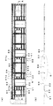
図1は本発明の一実施の形態である鉄道車両の側構体の横断面図、図2は前記側構体が用いられた鉄道車両の斜視図、図3(a)(b)(c)はそれぞれ下降窓開口、固定窓開口及び出入り口となる部分の断面図である。 FIG. 1 is a cross-sectional view of a side structure of a railway vehicle according to an embodiment of the present invention, FIG. 2 is a perspective view of a railway vehicle using the side structure, and FIGS. It is sectional drawing of the part which becomes a downward window opening, a fixed window opening, and an entrance / exit, respectively.
図1に示すように、鉄道車両の構体1は、左右の側構体2L,2Rと、これらの左右の側構体2L,2Rの上端部を連結する屋根構体3と、前記左右の側構体2L,2Rの下端部同士を連結する台枠4とを備える。
As shown in FIG. 1, a
右の側構体2Rは、例えば図2に示すように、上下方向の中央部分に、上下方向に配置され相互に接合される4つの押し出し形材11を備える。これら4つの押し出し形材11の上下には、それらより上下方向の長さが短い2つの押し出し形材12,13がそれぞれ接合されている。そして、この側構体2Rには、図2及び図3(a)〜(c)に示すように、側構体2Rの下降窓開口、固定窓開口及び出入り口となる部分には、押し出し形材の一部が切除されて、開口S1,S2,S3が形成される。
For example, as shown in FIG. 2, the
押し出し形材11は、図4に示すように、ダブルスキン構造の中央部分11Aと、その両側にそれぞれ連続して設けられるシングルスキン構造の端部部分11Bとを有する。このダブルスキン構造の中央部分11Aは、車体外側(表面露出部)となる外側の面板部11aと、この外側の面板部11aと平行に延び車体内側となる内側の面板部11bと、第1および内側の面板部11a,11bに直交する方向に延びそれらをつなぐ複数の鉛直ウエブ部11cとを有する。
As shown in FIG. 4, the
そして、外側の面板部11aの延長部分としてのシングルスキン構造の端部部分11Bが中央部分11Aの両側に連続して設けられている。この端部部分11Bの端縁同士は、図5に示すように、例えば摩擦攪拌接合により接合される。また、押し出し形材12,13についても同様にして接合される。これらの押し出し形材11〜13が接合されることで、鉄道車両の側構体2R(または2L)となるパネルが形成される。なお、Wは窓ガラスである。
And the edge part 11B of the single skin structure as an extension part of the outer faceplate part 11a is provided in succession on both sides of the central part 11A. The edges of the end portion 11B are joined together by, for example, friction stir welding as shown in FIG. Further, the
換言すれば、1つの押し出し形材11全体をみれば、外側の面板部11aは、内側の面板部11bよりも幅広で、その端縁部が、別の押し出し形材の外側の面板部11aの端縁部と接合可能とされ、それらを接合することで側構体2L,2Rとなるパネルが形成される。
In other words, when one entire
また、内側の面板部11bの外表面側には、隣り合う鉛直ウエブ部11cの間に対応する部分の幅方向(形材長手方向に直交する方向)の中心において、形材長手方向に延びる、目印ラインとして機能する直線状の微小凸部11e(高さ0.3mm程度)が形成されている。この微小凸部11eは、内側の面板部11bに、吊り溝部を形成するための長孔11fを形材長手方向に後加工により形成する際の目印とするものである。この長孔11fには、後述するように、内装材取り付け用の支持ボルトTの頭部T1が挿入される。なお、目印ラインとして機能する微小凸部11eに代えて、微小凹部とすることも可能である。 Further, on the outer surface side of the inner face plate portion 11b, it extends in the shape longitudinal direction at the center in the width direction (direction perpendicular to the shape longitudinal direction) of the corresponding portion between the adjacent vertical web portions 11c. A linear minute convex portion 11e (having a height of about 0.3 mm) that functions as a mark line is formed. The minute convex portion 11e serves as a mark when forming a long hole 11f for forming a hanging groove portion in the inner face plate portion 11b by post-processing in the longitudinal direction of the shape member. As will be described later, the head T1 of the support bolt T for attaching the interior material is inserted into the long hole 11f. Note that, instead of the minute convex portion 11e that functions as a mark line, a minute concave portion may be used.
このようにすれば、押し出し形材11を、たとえばFSW接合により接合して側構体2Lを形成する前あるいは接合して形成した後に、微小凸部11eを目印として必要箇所に、内装材取り付け用の支持ボルト挿入用の長孔11f、すなわち内装材取り付け用の支持ボルトTの頭部T1を係止可能である長孔11fを形材長手方向に形成することで、内側に突出しない吊り溝部を形成することができる。
In this way, for example, the extruded
特に、車両系式ごとに必要とされる吊り溝レールの位置が異なるので、従来は、異なる形材を用いて側構体を構成していたが、この実施の形態においては、後加工により吊り溝部を形成できるので、前述した4つの押し出し形材11については共通化を図ることとなり、コストダウンを図る上で有利となっている。
In particular, since the position of the suspension groove rail required for each vehicle system type is different, conventionally, the side structure is configured using different shapes, but in this embodiment, the suspension groove portion is formed by post-processing. Therefore, the above-described four
各鉛直ウエブ部11cは、形材厚さ方向の中間部位に、面板部11a,11bと平行に延びる規制凸部11dが互いに対向するように形成されている。規制凸部11dによって、長孔11fを通じて頭部T1が挿入される支持ボルトTの、ボルト軸方向の自由な動きを規制するようになっている。つまり、隣り合う2つの鉛直ウエブ部11cと、それに設けられる2つの規制凸部11dとによって、長孔11fが後加工により形成された部分において、従来の吊り溝レールと同様な機能が発揮されることになる。 Each vertical web part 11c is formed in the intermediate part of the profile thickness direction so that the regulation convex part 11d extended in parallel with faceplate part 11a, 11b mutually opposes. The restricting projection 11d restricts the free movement of the support bolt T into which the head T1 is inserted through the long hole 11f in the bolt axis direction. That is, a function similar to that of a conventional hanging groove rail is exhibited in a portion in which the long hole 11f is formed by post-processing by the two adjacent vertical web portions 11c and the two restricting convex portions 11d provided thereon. It will be.
また、ダブルスキン構造の中央部分11Aの端部は、内側の面板部11b側において、段差部11gが形成され、その段差部11gを形成する面板部11b’の端縁が傾斜ウエブ部11hを介して外側の面板部11aに結合されている。 Further, the end portion of the center portion 11A of the double skin structure is formed with a step portion 11g on the inner face plate portion 11b side, and the end edge of the face plate portion 11b ′ forming the step portion 11g is interposed through the inclined web portion 11h. And is connected to the outer face plate portion 11a.
このような段差部11gを設けているのは、前記パネルを形成する際に接合される別の押し出し形材の段差部との間に亘って平板である補強板21(図5参照)を設けることを可能とするためであり、この補強板21を設けることで、必要に応じて車体剛性を高めることができるようになっている。例えば図6及び図7に示すように、出入り口S3に隣接する戸袋部U1,U2において、入口柱22と、出入り口S3とは反対側に入口柱22と平行に配置される戸尻柱23との間、入口柱22と開口S2に設けられた柱24との間においては、ダブルスキン構造の間でシングルスキン構造となるが、その部分(押し出し形材の接合部分)に対し、段差部11gの間に架け渡すように補強板21を設けることで、シングルスキン構造の端部分11Bをあたかもダブルスキン構造であるかの如くして、車体剛性を高めることができる。
Such a stepped portion 11g is provided with a reinforcing plate 21 (see FIG. 5) that is a flat plate between the stepped portion of another extruded shape member joined when the panel is formed. In order to make this possible, by providing the reinforcing
ところで、出入り口となる開口S3は、通常側面視でほぼ矩形状となるので、それらの下側隅部には、応力が集中するのを回避するために、開口S3の下側隅部Rを、湾曲形状としている。 By the way, since the opening S3 serving as the entrance / exit is generally rectangular in a side view, the lower corner R of the opening S3 is formed in order to avoid stress concentration at the lower corners thereof. It has a curved shape.
この開口S3の下側隅部Rに対応する部分には、図9に示すように、押し出し形材11ではなく、押し出し形材13が配置される、この押し出し形材13は、前述した押し出し形材11(例えば図4参照)と基本的には同じ構造で、図10に示すように、ダブルスキン構造の中央部分13Aと、その両側にそれぞれ連続して設けられるシングルスキン構造の端部部分13Bとを有する。このダブルスキン構造の中央部分13Aは、車体外側(表面露出部)となる外側の面板部13aと、この外側の面板部13aと平行に延び車体内側となる内側の面板部13bと、外側および内側の面板部13a,13bに直交する方向に延びそれらをつなぐ複数の鉛直ウエブ部13cとを有する。そして、外側の面板部13aのうち、出入り口となる開口S3の下側隅部Rに対応する部分の肉厚は、開口S3の下側隅部Rとしての必要な剛性を確保するために、他の部分の面板部13a,13bの3倍程度の肉厚の厚肉の面板部13aaとされている。なお、この厚肉の面板部13aaの部分では、他の面板部13aの部分よりも鉛直ウエブ部13c’が短くなるのはいうまでもない。
In the portion corresponding to the lower corner R of the opening S3, as shown in FIG. 9, an
この押し出し形材13(厚肉の面板部13aaの部分)の一部を切削により除去することで、開口S3の下側隅部Rが、湾曲形状とされる。これにより、下側隅部Rが押し出し形材13自体によって形成される。なお、この下側隅部R(湾曲形状の部分)の内側であって入口柱22の開口S3側においては、内側の面板部13bや鉛直ウエブ部13cも切削により除去されている。
By removing a part of the extruded shape member 13 (part of the thick face plate portion 13aa) by cutting, the lower corner R of the opening S3 has a curved shape. Thus, the lower corner R is formed by the extruded
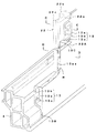
また、開口S3付近で押し出し形材13の内側には、構体上下方向に延びる入口柱22が設けられている。この入口柱22は、外側面を構成する外板部22aと、その外板部の内側に設けられ構体上下方向にほぼ平行に延びる一対の側柱部22b,22cとを備える。
Further, an
そして、図11(a)(b)及び図12(a)に示すように、押し出し形材13の外側の面板部であって厚肉に形成されている部分13aaの厚さは、入口柱22の外板部22aの厚さとほぼ同じ厚さとされている。そして、押し出し形材13と、入口柱22とは、溶接により接合されている(図11の溶接部分M1,M2,M3,M4参照)。
11 (a), 11 (b) and 12 (a), the thickness of the portion 13aa which is the outer face plate portion of the extruded
具体的には、押し出し形材13のうち下側隅部Rを形成する部分の上側であって入口柱22に対応する部位において、押し出し形材13を切り欠くことにより係合部13Cが形成されている一方、入口柱22は、外板部22aの下側部分(一部)が切除されて、係合部13Cに対応する被係合部22Aが形成されている。この被係合部22Aに係合部13Cを係合させることで、外板部22aの切除面に外側の面板部13aaの上側切り欠き面が接触し、側柱部22bに内側の面板部13b及び鉛直ウエブ部13cの切り欠き面が接触しかつ、面板部13aaの内側面に一対の側柱部22b,22cが接触する状態で、それらが溶接により接合されて、開口S3の下側隅部Rをまたぐように押し出し形材13が配置される。
Specifically, an engaging
この係合部分では、押し出し形材13の面板部13a,13aaの外側面が、上側の入口柱22(外板部22a)の外側面に面一に連続して、側構体2Rの外側面を形成するようになっている。これにより、必要な剛性が確保される。
In this engaging portion, the outer side surfaces of the face plate portions 13a and 13aa of the extruded
このようにすれば、押し出し形材13(母材)そのもので開口の下側隅部Rを構成するので、この部分の押し出し形材13の面板部13aaが、通常の板厚では剛性が不足するため、前述したように下側隅部に相当する位置の面板部13aaを厚肉にしている。
In this way, since the extruded shape member 13 (base material) itself forms the lower corner R of the opening, the rigidity of the face plate portion 13aa of the extruded
これにより、応力が集中する出入り口における下側隅部Rは、母材となるため、溶接により厚肉の補強板を取り付ける場合よりも小さい板厚で疲労強度を向上させることができる。よって、厚肉の補強板を溶接により設ける必要がないので、溶接欠陥がなく、不測の事態を回避することもできる。 As a result, the lower corner R at the doorway where stress is concentrated serves as a base material, so that the fatigue strength can be improved with a smaller plate thickness than when a thick reinforcing plate is attached by welding. Therefore, since it is not necessary to provide a thick reinforcing plate by welding, there is no welding defect and an unexpected situation can be avoided.
前記実施の形態では、開口S3の下側隅部を下側隅部Rとしているが、出入り口となる開口S3の上側隅部や窓開口となる開口S1,S2の上下隅部も(図2の鎖線で囲んだ部分参照)、前述した出入り口となる開口S3の下側隅部と同様に構成することができるのはいうまでもない。 In the above embodiment, the lower corner of the opening S3 is the lower corner R. However, the upper corner of the opening S3 serving as the doorway and the upper and lower corners of the openings S1 and S2 serving as the window openings (see FIG. 2). Needless to say, it can be configured in the same manner as the lower corner of the opening S3 serving as the aforementioned entrance / exit.
1 鉄道車両の構体
2L,2R 側構体
11,12,13 押し出し形材
11g 段差部
13A 中央部分
13B 端部部分
13C 係合部
11a,11b 面板部
13a,13aa 面板部
13c 鉛直ウエブ部
21 補強板
22 入口柱
22a 外板部
22b 支柱部
22A 被係合部
S3 開口
R 下側隅部
DESCRIPTION OF
Claims (6)
前記押し出し形材に形成され、円弧形状の隅部を有する開口部と、
前記開口部の左右端の少なくともいずれか一方に設けられ、車両鉛直方向に延在する入口柱とを備え、
前記押し出し形材は、前記開口部の隅部の上端に係合部を有し、前記隅部における前記外側面板部の厚さが前記内側面板部の厚さよりも厚く、
前記入口柱は、その下端部に、前記係合部に係合する被係合部を有する、鉄道車両の側構体。 An outer surface plate portion provided outside the railway vehicle and extending in the longitudinal direction of the vehicle, an inner surface plate portion disposed in parallel with the outer surface plate portion, and provided on the inner side of the rail vehicle, the outer surface plate portion and the inner surface An extruded profile having a plurality of web portions connecting the face plate portions;
An opening having an arcuate corner formed in the extruded profile ;
Provided at at least one of the left and right ends of the opening, and includes an entrance post extending in the vehicle vertical direction,
The extruded frame members has an engagement portion at an upper end corner portion of the opening portion, the thickness of the outer side plate portions in the corners rather thick than the thickness of the inner side plate portion,
The entrance column has a engaged structure that engages with the engaging portion at a lower end portion thereof .
前記外側面板部に対して略面一となるように設けられ、前記開口部の前記隅部を除いて車両鉛直方向に延在する外板部と、
前記外板部に対して前記鉄道車両の内側に設けられ、車両鉛直方向に延在する側柱部とを有し、
前記隅部における前記外側面板部の厚さが、前記外板部の厚さと略同一である、請求項1に記載の鉄道車両の側構体。 The entrance pillar is
An outer plate provided so as to be substantially flush with the outer side plate, and extending in the vehicle vertical direction except for the corner of the opening;
It is provided inside the railway vehicle with respect to the outer plate part, and has a side pillar part extending in the vehicle vertical direction,
The thickness of the outer side plate portions of the corners, the thickness substantially the same as the skin portion, the side structure of the railway vehicle according to claim 1.
前記上部側構体は、
前記鉄道車両の外側に設けられる第1外側面板部と、前記鉄道車両の内側に設けられる第1内側面板部と、前記第1外側面板部と第1内側面板部とを連結する複数の第1ウエブ部と、前記開口部に対応する位置に形成された第1凹部とを有し、
前記下部側構体は、
前記鉄道車両の外側に設けられる第2外側面板部と、前記鉄道車両の内側に設けられる第2内側面板部と、前記第2外側面板部と前記第2内側面板部とを連結する複数の第2ウエブ部と、前記開口部に対応する位置に形成された第2凹部と、前記開口部の隅部の上端に係合部とを有し、
前記隅部における前記第2外側面板部の厚さが、前記第2内側面板部の厚さより厚く、
前記入口柱は、その下端部に、前記係合部に係合する被係合部を有する、鉄道車両の側構体。 A plurality of openings formed by joining an upper structure and a lower structure extending in the longitudinal direction of the vehicle, provided at predetermined intervals along the longitudinal direction of the vehicle, and having a circular arc shape at the corners, and the opening A side structure of a railway vehicle that is provided on at least one of the left and right ends of the section and includes an entrance post extending in the vehicle vertical direction ,
The upper side structure is
A first outer side plate provided on the outside of the railway vehicle, a first inner side plate provided on the inner side of the rail vehicle, and a plurality of first connecting the first outer side plate and the first inner side plate. A web portion and a first recess formed at a position corresponding to the opening,
The lower structure is
A second outer side plate provided on the outside of the railway vehicle; a second inner side plate provided on the inner side of the railway vehicle; and a plurality of second connecting the second outer side plate and the second inner side plate. 2 web portions, a second recess formed at a position corresponding to the opening, and an engaging portion at the upper end of the corner of the opening ,
The thickness of the second outer surface plate portion in the corners, rather thick than the thickness of said second inner surface plate portion,
The entrance column has a engaged structure that engages with the engaging portion at a lower end portion thereof .
車両鉛直方向下側に突出してシングルスキン構造を構成する第1端部をさらに有し、
前記下部側構体は、
車両鉛直方向上側に突出してシングルスキン構造を構成し、前記第1端部と接合される第2端部をさらに有し、
前記シングルスキン構造に対応する部分において、前記第1内側面板部と前記第2内側面板部とを架け渡す補強部材をさらに有する、請求項4に記載の鉄道車両の側構体。 The upper side structure is
A first end portion projecting downward in the vehicle vertical direction to form a single skin structure;
The lower structure is
Projecting upward in the vehicle vertical direction to form a single skin structure, further comprising a second end joined to the first end;
The side structure of a railway vehicle according to claim 4 , further comprising a reinforcing member that bridges the first inner side plate and the second inner side plate at a portion corresponding to the single skin structure.
前記補強部材は、前記入口柱と前記戸尻柱との間であって、車両長手方向に延在する、請求項5に記載の鉄道車両の側構体。 Further comprising a Tojiri column provided parallel to the entrance column,
6. The side structure of a railway vehicle according to claim 5 , wherein the reinforcing member extends between the entrance post and the door bottom post and extends in the longitudinal direction of the vehicle.
Priority Applications (1)
| Application Number | Priority Date | Filing Date | Title |
|---|---|---|---|
| JP2008210234A JP4854715B2 (en) | 2008-08-19 | 2008-08-19 | Railcar side structure |
Applications Claiming Priority (1)
| Application Number | Priority Date | Filing Date | Title |
|---|---|---|---|
| JP2008210234A JP4854715B2 (en) | 2008-08-19 | 2008-08-19 | Railcar side structure |
Publications (3)
| Publication Number | Publication Date |
|---|---|
| JP2010047029A JP2010047029A (en) | 2010-03-04 |
| JP2010047029A5 JP2010047029A5 (en) | 2011-08-18 |
| JP4854715B2 true JP4854715B2 (en) | 2012-01-18 |
Family
ID=42064511
Family Applications (1)
| Application Number | Title | Priority Date | Filing Date |
|---|---|---|---|
| JP2008210234A Active JP4854715B2 (en) | 2008-08-19 | 2008-08-19 | Railcar side structure |
Country Status (1)
| Country | Link |
|---|---|
| JP (1) | JP4854715B2 (en) |
Families Citing this family (8)
| Publication number | Priority date | Publication date | Assignee | Title |
|---|---|---|---|---|
| JP5315303B2 (en) * | 2010-07-27 | 2013-10-16 | 川崎重工業株式会社 | Rail vehicle structure |
| JP5342532B2 (en) * | 2010-10-05 | 2013-11-13 | 三菱重工業株式会社 | Manufacturing method of body frame |
| CN102514580A (en) * | 2011-12-14 | 2012-06-27 | 中国北车集团大连机车车辆有限公司 | Vehicle body with integral window corner and railway vehicle |
| JP5970692B2 (en) * | 2012-03-06 | 2016-08-17 | 日本軽金属株式会社 | Method for joining members, method for manufacturing freight transport vehicle, and method for manufacturing freight transport container |
| IN2014DN07780A (en) * | 2012-03-22 | 2015-05-15 | Hitachi Ltd | |
| KR102082388B1 (en) | 2012-10-23 | 2020-02-27 | 반도 카가쿠 가부시키가이샤 | Drive belt |
| JP6490281B1 (en) * | 2018-05-08 | 2019-03-27 | 日本車輌製造株式会社 | Railway car |
| CN115230765B (en) * | 2022-07-27 | 2023-06-13 | 中车株洲电力机车有限公司 | Rail vehicle door angle structure and vehicle body structure |
Family Cites Families (14)
| Publication number | Priority date | Publication date | Assignee | Title |
|---|---|---|---|---|
| JPS5842840B2 (en) * | 1978-05-17 | 1983-09-22 | 藤工業株式会社 | Surface printing method |
| JPH078646B2 (en) * | 1985-04-12 | 1995-02-01 | 株式会社日立製作所 | Railway vehicle body structure |
| JPH0645341B2 (en) * | 1989-01-18 | 1994-06-15 | 株式会社日立製作所 | Side structure of railway vehicle |
| JPH09169267A (en) * | 1995-12-20 | 1997-06-30 | Hitachi Ltd | Vehicle body |
| JP3807766B2 (en) * | 1996-02-20 | 2006-08-09 | 株式会社日立製作所 | Manufacturing method of railway vehicle structure |
| JP3189720B2 (en) * | 1997-01-08 | 2001-07-16 | 株式会社日立製作所 | Vehicle structure |
| JP3494847B2 (en) * | 1997-05-20 | 2004-02-09 | 株式会社日立製作所 | Car body |
| JPH1111305A (en) * | 1997-06-19 | 1999-01-19 | Hitachi Ltd | Rolling stock structure |
| JPH1159413A (en) * | 1997-08-20 | 1999-03-02 | Hitachi Ltd | Vehicular body of rolling stock |
| JP2942534B1 (en) * | 1998-03-19 | 1999-08-30 | 株式会社日立製作所 | Railcar body |
| JP3459205B2 (en) * | 1999-09-06 | 2003-10-20 | 株式会社日立製作所 | Structure and method of manufacturing the same |
| JP3552978B2 (en) * | 2000-01-27 | 2004-08-11 | 株式会社日立製作所 | Hollow profile |
| JP2008055445A (en) * | 2006-08-30 | 2008-03-13 | Hitachi Ltd | Method for manufacturing structure, and such structure |
| JP4854707B2 (en) * | 2008-06-16 | 2012-01-18 | 川崎重工業株式会社 | Railcar structures |
-
2008
- 2008-08-19 JP JP2008210234A patent/JP4854715B2/en active Active
Also Published As
| Publication number | Publication date |
|---|---|
| JP2010047029A (en) | 2010-03-04 |
Similar Documents
| Publication | Publication Date | Title |
|---|---|---|
| JP4854715B2 (en) | Railcar side structure | |
| US9751539B2 (en) | Side bodyshell of railcar | |
| US9487221B2 (en) | Railcar bodyshell and railcar including same | |
| JP4854707B2 (en) | Railcar structures | |
| EP1944213B1 (en) | Car structure | |
| JP6748548B2 (en) | Bone structure of railway vehicle and side structure including the same | |
| JP5096732B2 (en) | Railcar structures | |
| JP2010149849A (en) | Side body structure of railroad vehicle | |
| JP6737681B2 (en) | Railway car | |
| JP6653730B2 (en) | Railcar | |
| JPH0739720Y2 (en) | Vehicle wife structure | |
| JP2017218110A (en) | Railroad vehicle structure | |
| JP7241585B2 (en) | railroad vehicle structure | |
| JP2023030590A (en) | Railway vehicle body structure and railway vehicle | |
| JP2009056904A (en) | Alligator type cross member | |
| JP2013018369A (en) | Frame structure of rolling stock | |
| JP5470074B2 (en) | Railway vehicle structure and manufacturing method thereof | |
| JPH05665A (en) | Car body structure using light alloy extruded shape member | |
| JP6792962B2 (en) | Side structure and its manufacturing method | |
| JP7339127B2 (en) | rail car | |
| JP7456310B2 (en) | Vehicle side structure | |
| JP2007090960A (en) | Car body structure of railway vehicle | |
| JP7237692B2 (en) | railroad vehicle structure | |
| JP5567359B2 (en) | Railway vehicle structure and manufacturing method thereof | |
| JP2023101921A (en) | Railway vehicle and manufacturing method thereof |
Legal Events
| Date | Code | Title | Description |
|---|---|---|---|
| A521 | Request for written amendment filed |
Free format text: JAPANESE INTERMEDIATE CODE: A523 Effective date: 20110705 |
|
| A621 | Written request for application examination |
Free format text: JAPANESE INTERMEDIATE CODE: A621 Effective date: 20110705 |
|
| A871 | Explanation of circumstances concerning accelerated examination |
Free format text: JAPANESE INTERMEDIATE CODE: A871 Effective date: 20110705 |
|
| A975 | Report on accelerated examination |
Free format text: JAPANESE INTERMEDIATE CODE: A971005 Effective date: 20110720 |
|
| A131 | Notification of reasons for refusal |
Free format text: JAPANESE INTERMEDIATE CODE: A131 Effective date: 20110809 |
|
| A521 | Request for written amendment filed |
Free format text: JAPANESE INTERMEDIATE CODE: A523 Effective date: 20110929 |
|
| TRDD | Decision of grant or rejection written | ||
| A01 | Written decision to grant a patent or to grant a registration (utility model) |
Free format text: JAPANESE INTERMEDIATE CODE: A01 Effective date: 20111025 |
|
| A01 | Written decision to grant a patent or to grant a registration (utility model) |
Free format text: JAPANESE INTERMEDIATE CODE: A01 |
|
| A61 | First payment of annual fees (during grant procedure) |
Free format text: JAPANESE INTERMEDIATE CODE: A61 Effective date: 20111025 |
|
| FPAY | Renewal fee payment (event date is renewal date of database) |
Free format text: PAYMENT UNTIL: 20141104 Year of fee payment: 3 |
|
| R150 | Certificate of patent or registration of utility model |
Ref document number: 4854715 Country of ref document: JP Free format text: JAPANESE INTERMEDIATE CODE: R150 Free format text: JAPANESE INTERMEDIATE CODE: R150 |
|
| S111 | Request for change of ownership or part of ownership |
Free format text: JAPANESE INTERMEDIATE CODE: R313111 |
|
| R350 | Written notification of registration of transfer |
Free format text: JAPANESE INTERMEDIATE CODE: R350 |
|
| R250 | Receipt of annual fees |
Free format text: JAPANESE INTERMEDIATE CODE: R250 |