JP5315303B2 - Rail vehicle structure - Google Patents
Rail vehicle structure Download PDFInfo
- Publication number
- JP5315303B2 JP5315303B2 JP2010167968A JP2010167968A JP5315303B2 JP 5315303 B2 JP5315303 B2 JP 5315303B2 JP 2010167968 A JP2010167968 A JP 2010167968A JP 2010167968 A JP2010167968 A JP 2010167968A JP 5315303 B2 JP5315303 B2 JP 5315303B2
- Authority
- JP
- Japan
- Prior art keywords
- door
- doorway
- extruded shape
- railway vehicle
- shape member
- Prior art date
- Legal status (The legal status is an assumption and is not a legal conclusion. Google has not performed a legal analysis and makes no representation as to the accuracy of the status listed.)
- Active
Links
Images


Description
本発明は、鉄道車両の構体構造、特に側出入口の上部コーナ部の構造に関する。 The present invention relates to a structure of a railway vehicle, and more particularly to a structure of an upper corner portion of a side doorway.
従来、鉄道車両の側構体を、アルミニウム合金の押し出し形材を用いて製造する場合、前記押し出し形材の押し出し方向が車体長手方向に一致するように配置し、前記側構体に側出入口の開口部を形成する際に、側出入口の前後両端には戸先柱を配置して押し出し形材の端部を前記戸先柱で覆うことで塞いでいる。一方、側出入口の上側水平部は、押し出し形材が2つの面板部およびそれらを連結するウエブ板部を有する構造であることから、前記面板部またはウエブ板部を利用して形成することで、特別な部材を必要としないようにしている。 Conventionally, when a side structure of a railway vehicle is manufactured using an extruded shape of an aluminum alloy, the extruded shape is arranged so that the extrusion direction of the extruded shape coincides with the longitudinal direction of the vehicle body. When the door is formed, door-end pillars are arranged at both front and rear ends of the side doorway, and the ends of the extruded shape members are covered with the door-end pillars. On the other hand, the upper horizontal portion of the side entrance is a structure in which the extruded shape member has two face plate portions and a web plate portion that connects them, and therefore, by using the face plate portion or the web plate portion, Special members are not required.
このような構造の場合、戸先柱と側出入口の上側水平部とが交わる、側出入口の上側隅部において、応力が集中するのを低減する必要がある。そのため、前記上側隅部に、湾曲面が前記側出入口に臨む略三角形状の補強部材を別途溶接により固定している。 In the case of such a structure, it is necessary to reduce the concentration of stress at the upper corner of the side doorway where the door column and the upper horizontal part of the side doorway intersect. Therefore, a substantially triangular reinforcing member with a curved surface facing the side doorway is fixed to the upper corner by welding separately.
また、側出入口の全周にわたって縁材(枠部材)を摩擦攪拌接合するようにしたものも提案されている(例えば特許文献1,2参照)。
Further, there has also been proposed one in which an edge member (frame member) is friction stir welded over the entire periphery of the side doorway (see, for example,
前記側出入口の上側隅部に対し補強部材を溶接により設ける場合には、下記の問題があった。
・溶接量が多くなり、コスト面で不利である。
・溶接量が多くなり、溶接による熱歪みが生じ、外板の見栄えが低下する。
・補強部材と戸先柱および側出入口の上側水平部との接点が溶接部となり、作用する応力が高くなる部分に溶接部が集中することになり、強度上不利である。
When the reinforcing member is provided by welding to the upper corner portion of the side doorway, there are the following problems.
・ The amount of welding increases, which is disadvantageous in terms of cost.
・ The amount of welding increases, thermal distortion due to welding occurs, and the appearance of the outer plate deteriorates.
A contact point between the reinforcing member, the door column and the upper horizontal portion of the side doorway becomes a welded portion, and the welded portion concentrates on a portion where the acting stress increases, which is disadvantageous in terms of strength.
また、特許文献1,2に記載のものも、摩擦攪拌接合する部分の長さが長くなり、コスト面で不利である。
Also, the ones described in
本発明は、側出入口の全周にわたって縁材(枠部材)を設けることなく、戸先柱と側出入口の上側水平部とが交わる、側出入口の上側隅部の強度を、補強部材を用いることなく、確保できる鉄道車両の構体構造を提供することを目的とする。 The present invention uses a reinforcing member for the strength of the upper corner portion of the side doorway where the door column and the upper horizontal portion of the side doorway intersect without providing an edge member (frame member) over the entire circumference of the side doorway. An object of the present invention is to provide a railway vehicle structure that can be secured.
請求項1の発明は、側構体の外側面となる外側面板部と、前記外側面板部と平行に配置され、前記側構体の内側面となる内側面板部と、前記外側面板部と前記内側面板部とを連結する複数のウエブ板部とを有し、押し出し方向が車両長手方向となる押し出し形材と、前記押し出し形材に形成され、円弧形状の上側コーナ部を有する側出入口と、前記側出入口の左右端をそれぞれ塞ぐ戸先柱と、を備え、前記戸先柱は、上下方向に延在して前記側出入口の左右端を塞ぐ第1の部分と、前記第1の部分と一体に形成され、前記側出入口の前記上側コーナ部を覆うとともに、前記側出入口の上面部の一部まで延びる第2の部分と、を有し、前記第2の部分を除く前記側出入口の上面部は、前記押し出し形材の前記ウエブ板部によって形成される、ことを特徴とする。
このようにすれば、隅補強のための補強部材が必要なくなり、部品点数の低減を図ることができるとともに、重量軽減にも寄与する。また、溶接量も削減できるので、作業時間及び製造コストの削減が図れる。隅補強を廃止できるので、外板面に露出する溶接が大幅に削減され、見栄えが向上する。さらに、高い応力が発生するコーナ部から接合部分を離すことができる。
The invention according to
In this way, a reinforcing member for corner reinforcement is not necessary, the number of parts can be reduced, and the weight can be reduced. In addition, since the welding amount can be reduced, the working time and the manufacturing cost can be reduced. Since the corner reinforcement can be abolished, the welding exposed to the outer plate surface is greatly reduced, and the appearance is improved. Further, the joint portion can be separated from the corner portion where high stress is generated.
請求項2に記載のように、前記戸先柱は、本体部と、断面視において前記本体部に対して直交する方向に延びる2つの側縁部と、を有し、前記側縁部のうち、前記側構体の外側面側に位置する側縁部が、前記側構体の内側面側に位置する側縁部よりも、その長さが短い、ことが望ましい。
As described in
このようにすれば、フラットな本体部で側出入口の周縁となる前後面部を形成することができ、内側面側を形成する側縁部によって、側構体に形成される側出入口の周縁(切断面)を簡単に隠蔽することができる。 In this way, the front and rear surface portions that become the peripheral edge of the side doorway can be formed by the flat main body portion, and the peripheral edge (cut surface) of the side doorway formed in the side structure by the side edge portion that forms the inner surface side. ) Can be easily hidden.
請求項3に記載のように、前記側縁部のうち、前記側構体の外側面側に位置する側縁部は、その先端側に、傾斜部と延長部から構成された段差部をさらに含み、当該段差部において前記押し出し形材の前記外側面板部とが溶接接合される、とすることができる。The side edge part located in the outer surface side of the said side structure among the said side edge parts further contains the level | step-difference part comprised from the inclination part and the extension part in the front end side. In the step portion, the outer face plate portion of the extruded shape member can be welded.
請求項4に記載のように、前記押し出し形材は、前記側出入口の左右端から前記上側コーナ部にかけて、前記戸先柱の形状に対応するように切り欠き凹部が形成され、前記切り欠き凹部に前記戸先柱が嵌り込む、ことが望ましい。
このようにすれば、切り欠き凹部に戸先柱を嵌め込むだけで、それらの位置合わせを行うことができる。また、戸先柱、隅補強部分、開口上端水平部の接点が長手方向に配置された形材内になり、強度向上が図られる。
According to a fourth aspect of the present invention, in the extruded shape member, a notch recess is formed so as to correspond to the shape of the door column from the left and right ends of the side doorway to the upper corner portion, and the notch recess It is desirable that the door column is fitted into the door.
If it does in this way, those position alignment can be performed only by inserting a door-end pillar in a notch crevice. Moreover, the contact of the door-end pillar, the corner reinforcement part, and the opening upper end horizontal part is in the shape member arranged in the longitudinal direction, and the strength is improved.
請求項5に記載のように、側はりの上であって、前記側出入口の左右端の下端部に設けられ、円弧形状の下側コーナ部を有する側板をさらに備え、前記戸先柱は、その下端部に、前記側板に係合する切り欠き部をさらに有する、構成とすることができる。
According to
このようにすれば、戸先柱の下端部も、見栄えを損ねることなく、側出入口の下端部まで延ばすことができる。 If it does in this way, the lower end part of a door-end pillar can also be extended to the lower end part of a side entrance, without spoiling appearance.
本発明は、上記のように構成したから、隅補強のための補強部材が必要なくなり、部品点数の低減を図ることができる。また、溶接量も削減できるので、製造コストの削減が図れる。隅補強を廃止できるので、外板面に露出する溶接が大幅に削減され、見栄えが向上する。 Since the present invention is configured as described above, a reinforcing member for corner reinforcement is not necessary, and the number of parts can be reduced. In addition, since the welding amount can be reduced, the manufacturing cost can be reduced. Since the corner reinforcement can be abolished, the welding exposed to the outer plate surface is greatly reduced, and the appearance is improved.
以下、本発明の実施の形態を図面に沿って説明する。 Hereinafter, embodiments of the present invention will be described with reference to the drawings.
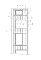
図1及び図2(a)(b)に示すように、側構体1が、押し出し方向が車体長手方向になるように複数の押し出し形材2を配置して構成される。なお、複数の押し出し形材の接合線をL1〜L5で示す。この側構体1に側出入口1Aが形成されている。
As shown in FIGS. 1 and 2 (a) and 2 (b), the
押し出し形材2は、2つの面板部2a,2bおよびそれらを連結するウエブ板部2cを有し、2つの面板部2a,2bのうち一方の面板部2aによって側構体1の外側面が形成される。この側出入口1Aは、押し出し形材2を接合して側構体1を形成した後、押し出し形材2の一部を切除して形成される。
The
側出入口1Aの上面部は、押し出し形材2のウエブ板部2cの側面(あるいは形材2の端面そのものであってもよい)を利用して構成されている。つまり、図2(a)(b)に示すように、押し出し形材2のウエブ板部2cの側面が、側出入口1Aの上面部の位置に一致するように配置され、そのウエブ板部2cの側面がそのまま、水平方向に延びる側出入口1Aの上面部となっている。
The upper surface portion of the side entrance 1A is configured by utilizing the side surface of the web plate portion 2c of the extruded shape member 2 (or the end surface of the
側構体1には、側出入口1Aの前後面部において、下側コーナ部を除き、上側コーナ部を超える辺りまで延びる切り欠き凹部1Bが形成され、この切り欠き凹部1Bに戸先柱11が嵌り込んでいる。つまり、切り欠き凹部1Bは、戸先柱11の形状に対応する形状に切り欠かれている。
The
切り欠き凹部1Bは、図3(a)(b)に示すように、側出入口1Aの上側コーナ部を超えた部位では、戸先柱11の幅に相当する大きさの上側凹部1Baとなっており、その幅を維持して、下側コーナ部まで延びている。また、側出入口1Aの下側コーナ部には、図2(b)及び図3(c)〜(e)に示すように、側はり14の上側に配置される押し出し形材2の面板部2aに湾曲コーナ板部2dが形成されている。
As shown in FIGS. 3A and 3B, the notch recess 1B becomes an upper recess 1Ba having a size corresponding to the width of the
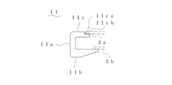
戸先柱11は、図4(a)(b)(c)及び図5,図6に示すように、側出入口1Aの下端部付近から上端部にかけて配置され側出入口1Aの前後面部を形成する直線状の第1の部分11Aと、側出入口1Aの上側コーナ部に相当する部位に配置され側出入口1Aの湾曲コーナ部を形成する第2の部分11Bとを有し、これらは一体に成形されたものである。また、戸先柱11は、断面においては、図5に示すように、フラットな断面略矩形状の本体部11aと、この本体部11aの両側縁から同一方向(側出入口1Aの外方向である押し出し形材2が存在する方向)、つまり本体部11aに直交する方向に平行に延びる2つの側縁部11b,11cとを有するチャンネル形状で、外側面側を形成する側縁部11cが、内側面側を形成する側縁部11bより短くなっている。側縁部11b,11cの長さを変えているのは、同じ長さであると両側縁部11b,11cを同じ位置で溶接することとなり、熱影響による歪が同じ位置で発生し、見映え、製作精度に影響するおそれがあるからである。
As shown in FIGS. 4 (a), (b), (c), and FIGS. 5 and 6, the door-
外側面側を形成する側縁部11cは、先端側に傾斜部11caを挟んで段差部を形成する延長部11cbを有し、図5に示すように、この段差部に押し出し形材2の面板部2aが嵌り込むようになっている。そして、傾斜部11caが溶接の際の開先を形成するように機能するとともに、延長部11cbが面板部2aの裏当金として機能し、側縁部11cと面板部2aとの溶接品質を確保できるようになっている。このように押し出し形材(側縁部11c)を形成しているので、開先加工等の作業が不要となり、作業時間の低減に有利である。 The side edge portion 11c that forms the outer surface side has an extension portion 11cb that forms a stepped portion with the inclined portion 11ca sandwiched at the tip side, and as shown in FIG. The part 2a is fitted. The inclined portion 11ca functions to form a groove for welding, and the extension portion 11cb functions as a backing metal for the face plate portion 2a to ensure the welding quality between the side edge portion 11c and the face plate portion 2a. It can be done. Since the extruded shape member (side edge portion 11c) is formed in this way, work such as groove processing becomes unnecessary, which is advantageous in reducing work time.
また、戸先柱11の上端部、つまり第2の部分11Bの先端部付近においては、側縁部11bが、図6に示すように切除されている。一方、戸先柱11の下端部には、湾曲コーナ板部2dに係合する切り欠き部11eが形成されている(図3(e)及び図4(b)参照)。つまり、第2の部分11Bの下端部において、側縁部が切除され、その部分に面板部2a(湾曲コーナ板部2d)が位置するようになっている。
Further, in the upper end portion of the door-
そして、側出入口1Aの切り欠き凹部1Bに戸先柱11が嵌り込んだ状態では、側出入口1Aを側構体1に形成するために各押し出し形材2に形成される切除面は、切り欠き凹部1Bに戸先柱11が嵌り込んでいることで、戸先柱11によって塞がれ、外観上見えなくなっている。そして、側出入口1Aの前後面部及び上面部の一部(ウエブ板部2cの側面によって形成される中央部を除く部分)は、戸先柱11によって形成される。
When the
また、図7(a)に示すように、押し出し形材の端面が形成している側出入口1Aの上面部に、連続して、戸先柱11の本体部11a(第2の部分11B)の面(内周湾曲面)が、図2(b)に示すように配置され、側出入口1Aの上面部の一部を形成している。
Moreover, as shown to Fig.7 (a), the main-body part 11a (2nd part 11B) of the door-
この本体部11a(第2の部分11B)の面(内周湾曲面)は、押し出し形材の端面が形成している側出入口1Aの上面部に接続される付近では水平方向に延びている。これにより、側構体1(押し出し形材2)と戸先柱11との接続部分は、直線部分で接続されていることになる。また、この部分においては、側縁部11bが切除されているので、押し出し形材2の切除面が露出するため、塞ぎ板12が設けられている。
The surface (inner peripheral curved surface) of the main body portion 11a (second portion 11B) extends in the horizontal direction in the vicinity of being connected to the upper surface portion of the side doorway 1A formed by the end surface of the extruded shape member. Thereby, the connection part of the side structure 1 (extruded shape member 2) and the door-
前記実施の形態では、押し出し形材としては、2つの面板部およびそれらを連結するウエブ板部を有するダブルスキン構造のものを用いているが、シングルスキン構造のものを用いることも可能である。この場合には、前記ダブルスキン構造において車体内方側の面板部を省略したものと同様の構造となり、側構体の外側面を形成する面板部と、この面板部に直交する方向であって車体内方側に延びるウエブ板部とを有する。 In the above-described embodiment, the extruded shape member has a double skin structure having two face plate portions and a web plate portion for connecting the two face plate portions, but a single skin structure shape can also be used. In this case, in the double skin structure, the structure is the same as that in which the face plate portion on the inner side of the vehicle body is omitted, and the face plate portion forming the outer surface of the side structure and the direction orthogonal to the face plate portion in the vehicle. A web plate portion extending toward the body side.
1 側構体
1A 側出入口
1B 切り欠き凹部
2 押し出し形材
2a,2b 面板部
2c ウエブ板部
11 戸先柱
11a 本体部
11b,11c 側縁部
11d 段差部
11A 第1の部分
11B 第2の部分
DESCRIPTION OF
Claims (5)
前記押し出し形材に形成され、円弧形状の上側コーナ部を有する側出入口と、
前記側出入口の左右端をそれぞれ塞ぐ戸先柱と、を備え、
前記戸先柱は、上下方向に延在して前記側出入口の左右端を塞ぐ第1の部分と、前記第1の部分と一体に形成され、前記側出入口の前記上側コーナ部を覆うとともに、前記側出入口の上面部の一部まで延びる第2の部分と、を有し、
前記第2の部分を除く前記側出入口の上面部は、前記押し出し形材の前記ウエブ板部によって形成される、鉄道車両の構体構造。 A plurality of outer surface plate portions that serve as outer surfaces of the side structures, an inner surface plate portion that is disposed in parallel with the outer surface plate portions and that serves as an inner surface of the side structure, and that connects the outer surface plate portions and the inner surface plate portions. An extruded shape member having a web plate portion, the extrusion direction being the vehicle longitudinal direction,
A side doorway formed in the extruded profile and having an arcuate upper corner;
A door post that closes the left and right ends of the side doorway,
The door pillar is formed integrally with the first portion extending in the vertical direction and closing the left and right ends of the side entrance, and covers the upper corner portion of the side entrance, A second portion extending to a part of the upper surface portion of the side doorway,
The structure of the railway vehicle , wherein an upper surface portion of the side doorway excluding the second portion is formed by the web plate portion of the extruded shape member .
前記側縁部のうち、前記側構体の外側面側に位置する側縁部が、前記側構体の内側面側に位置する側縁部よりも、その長さが短い、請求項1に記載の鉄道車両の構体構造。 The door pillar has a main body part and two side edges extending in a direction orthogonal to the main body part in a cross-sectional view,
The side edge part located in the outer surface side of the said side structure among the said side edge parts is shorter than the side edge part located in the inner surface side of the said side structure. The structure of a railway vehicle.
前記戸先柱は、その下端部に、前記側板に係合する切り欠き部をさらに有する、請求項1〜4のいずれか1つに記載の鉄道車両の構体構造。 A side plate on the side beam, provided at the lower ends of the left and right ends of the side doorway, further comprising a side plate having an arcuate lower corner portion;
The structure of a railway vehicle according to any one of claims 1 to 4, wherein the door-end pillar further includes a notch that engages with the side plate at a lower end thereof .
Priority Applications (1)
| Application Number | Priority Date | Filing Date | Title |
|---|---|---|---|
| JP2010167968A JP5315303B2 (en) | 2010-07-27 | 2010-07-27 | Rail vehicle structure |
Applications Claiming Priority (1)
| Application Number | Priority Date | Filing Date | Title |
|---|---|---|---|
| JP2010167968A JP5315303B2 (en) | 2010-07-27 | 2010-07-27 | Rail vehicle structure |
Publications (3)
| Publication Number | Publication Date |
|---|---|
| JP2012025324A JP2012025324A (en) | 2012-02-09 |
| JP2012025324A5 JP2012025324A5 (en) | 2013-07-18 |
| JP5315303B2 true JP5315303B2 (en) | 2013-10-16 |
Family
ID=45778783
Family Applications (1)
| Application Number | Title | Priority Date | Filing Date |
|---|---|---|---|
| JP2010167968A Active JP5315303B2 (en) | 2010-07-27 | 2010-07-27 | Rail vehicle structure |
Country Status (1)
| Country | Link |
|---|---|
| JP (1) | JP5315303B2 (en) |
Families Citing this family (1)
| Publication number | Priority date | Publication date | Assignee | Title |
|---|---|---|---|---|
| CN110065509B (en) * | 2019-05-08 | 2020-08-07 | 中车青岛四方机车车辆股份有限公司 | Car body door corner structure, car body and rail train |
Family Cites Families (9)
| Publication number | Priority date | Publication date | Assignee | Title |
|---|---|---|---|---|
| JP3494847B2 (en) * | 1997-05-20 | 2004-02-09 | 株式会社日立製作所 | Car body |
| JP2000351365A (en) * | 1999-06-11 | 2000-12-19 | Hitachi Ltd | Car body |
| JP3575749B2 (en) * | 2000-11-17 | 2004-10-13 | 株式会社日立製作所 | Friction stir welding method |
| JP2003039182A (en) * | 2001-07-24 | 2003-02-12 | Hitachi Ltd | Friction stir welding method and rotary tool |
| JP3751236B2 (en) * | 2001-08-24 | 2006-03-01 | 株式会社日立製作所 | Friction stir welding method |
| JP4484539B2 (en) * | 2004-02-19 | 2010-06-16 | 川崎重工業株式会社 | Railcar side structure |
| JP4620033B2 (en) * | 2006-11-20 | 2011-01-26 | 日本車輌製造株式会社 | Railway vehicle structure and frame member mounting method |
| JP4854707B2 (en) * | 2008-06-16 | 2012-01-18 | 川崎重工業株式会社 | Railcar structures |
| JP4854715B2 (en) * | 2008-08-19 | 2012-01-18 | 川崎重工業株式会社 | Railcar side structure |
-
2010
- 2010-07-27 JP JP2010167968A patent/JP5315303B2/en active Active
Also Published As
| Publication number | Publication date |
|---|---|
| JP2012025324A (en) | 2012-02-09 |
Similar Documents
| Publication | Publication Date | Title |
|---|---|---|
| JP4640127B2 (en) | Door waist structure | |
| US10549609B2 (en) | Door frame | |
| US10399520B2 (en) | Vehicle body structure | |
| JP6150573B2 (en) | door | |
| JP6748538B2 (en) | Vehicle door frame | |
| JP5890370B2 (en) | Door frame | |
| WO2008068860A1 (en) | Body skeleton structure of rolling stock | |
| JP6816676B2 (en) | Body superstructure | |
| JP2015098247A (en) | Sash member | |
| JP2010047029A (en) | Side body structure for railway vehicle | |
| JPWO2009101981A1 (en) | Bumper structure | |
| JP5315303B2 (en) | Rail vehicle structure | |
| JP2010241247A (en) | Underrun protector structure for truck | |
| HUE034295T2 (en) | A two part spacer with overlapping surfaces and method of producing such a spacer | |
| WO2013015271A1 (en) | Vehicle door | |
| JP2009190621A (en) | Mounting structure of beltline mall | |
| JP4294581B2 (en) | Vehicle front pillar structure | |
| JP5876361B2 (en) | Vehicle door frame structure | |
| JP4943115B2 (en) | Car body connection structure | |
| JP2020059406A (en) | Door frame for vehicle | |
| JP2006182092A (en) | Front pillar structure of vehicle | |
| JP5217487B2 (en) | Sound insulation structure at the fender end | |
| JP2012025324A5 (en) | ||
| JP5710237B2 (en) | Vehicle door frame structure | |
| KR101066910B1 (en) | Still wall |
Legal Events
| Date | Code | Title | Description |
|---|---|---|---|
| A521 | Request for written amendment filed |
Free format text: JAPANESE INTERMEDIATE CODE: A523 Effective date: 20130530 |
|
| A621 | Written request for application examination |
Free format text: JAPANESE INTERMEDIATE CODE: A621 Effective date: 20130530 |
|
| A871 | Explanation of circumstances concerning accelerated examination |
Free format text: JAPANESE INTERMEDIATE CODE: A871 Effective date: 20130530 |
|
| A975 | Report on accelerated examination |
Free format text: JAPANESE INTERMEDIATE CODE: A971005 Effective date: 20130612 |
|
| TRDD | Decision of grant or rejection written | ||
| A01 | Written decision to grant a patent or to grant a registration (utility model) |
Free format text: JAPANESE INTERMEDIATE CODE: A01 Effective date: 20130625 |
|
| A61 | First payment of annual fees (during grant procedure) |
Free format text: JAPANESE INTERMEDIATE CODE: A61 Effective date: 20130708 |
|
| R150 | Certificate of patent or registration of utility model |
Free format text: JAPANESE INTERMEDIATE CODE: R150 Ref document number: 5315303 Country of ref document: JP Free format text: JAPANESE INTERMEDIATE CODE: R150 |
|
| S111 | Request for change of ownership or part of ownership |
Free format text: JAPANESE INTERMEDIATE CODE: R313111 |
|
| R350 | Written notification of registration of transfer |
Free format text: JAPANESE INTERMEDIATE CODE: R350 |
|
| R250 | Receipt of annual fees |
Free format text: JAPANESE INTERMEDIATE CODE: R250 |