JP4854692B2 - Injection molded resin face gear - Google Patents
Injection molded resin face gear Download PDFInfo
- Publication number
- JP4854692B2 JP4854692B2 JP2008035918A JP2008035918A JP4854692B2 JP 4854692 B2 JP4854692 B2 JP 4854692B2 JP 2008035918 A JP2008035918 A JP 2008035918A JP 2008035918 A JP2008035918 A JP 2008035918A JP 4854692 B2 JP4854692 B2 JP 4854692B2
- Authority
- JP
- Japan
- Prior art keywords
- cylindrical portion
- web
- end side
- tooth
- face gear
- Prior art date
- Legal status (The legal status is an assumption and is not a legal conclusion. Google has not performed a legal analysis and makes no representation as to the accuracy of the status listed.)
- Active
Links
Images


Classifications
-
- F—MECHANICAL ENGINEERING; LIGHTING; HEATING; WEAPONS; BLASTING
- F16—ENGINEERING ELEMENTS AND UNITS; GENERAL MEASURES FOR PRODUCING AND MAINTAINING EFFECTIVE FUNCTIONING OF MACHINES OR INSTALLATIONS; THERMAL INSULATION IN GENERAL
- F16H—GEARING
- F16H55/00—Elements with teeth or friction surfaces for conveying motion; Worms, pulleys or sheaves for gearing mechanisms
- F16H55/02—Toothed members; Worms
- F16H55/06—Use of materials; Use of treatments of toothed members or worms to affect their intrinsic material properties
-
- B—PERFORMING OPERATIONS; TRANSPORTING
- B29—WORKING OF PLASTICS; WORKING OF SUBSTANCES IN A PLASTIC STATE IN GENERAL
- B29C—SHAPING OR JOINING OF PLASTICS; SHAPING OF MATERIAL IN A PLASTIC STATE, NOT OTHERWISE PROVIDED FOR; AFTER-TREATMENT OF THE SHAPED PRODUCTS, e.g. REPAIRING
- B29C45/00—Injection moulding, i.e. forcing the required volume of moulding material through a nozzle into a closed mould; Apparatus therefor
- B29C45/0025—Preventing defects on the moulded article, e.g. weld lines, shrinkage marks
-
- F—MECHANICAL ENGINEERING; LIGHTING; HEATING; WEAPONS; BLASTING
- F16—ENGINEERING ELEMENTS AND UNITS; GENERAL MEASURES FOR PRODUCING AND MAINTAINING EFFECTIVE FUNCTIONING OF MACHINES OR INSTALLATIONS; THERMAL INSULATION IN GENERAL
- F16H—GEARING
- F16H55/00—Elements with teeth or friction surfaces for conveying motion; Worms, pulleys or sheaves for gearing mechanisms
- F16H55/02—Toothed members; Worms
- F16H55/17—Toothed wheels
-
- B—PERFORMING OPERATIONS; TRANSPORTING
- B29—WORKING OF PLASTICS; WORKING OF SUBSTANCES IN A PLASTIC STATE IN GENERAL
- B29L—INDEXING SCHEME ASSOCIATED WITH SUBCLASS B29C, RELATING TO PARTICULAR ARTICLES
- B29L2015/00—Gear wheels or similar articles with grooves or projections, e.g. control knobs
- B29L2015/003—Gears
-
- F—MECHANICAL ENGINEERING; LIGHTING; HEATING; WEAPONS; BLASTING
- F16—ENGINEERING ELEMENTS AND UNITS; GENERAL MEASURES FOR PRODUCING AND MAINTAINING EFFECTIVE FUNCTIONING OF MACHINES OR INSTALLATIONS; THERMAL INSULATION IN GENERAL
- F16H—GEARING
- F16H55/00—Elements with teeth or friction surfaces for conveying motion; Worms, pulleys or sheaves for gearing mechanisms
- F16H55/02—Toothed members; Worms
- F16H55/17—Toothed wheels
- F16H2055/173—Crown gears, i.e. gears have axially arranged teeth
-
- Y—GENERAL TAGGING OF NEW TECHNOLOGICAL DEVELOPMENTS; GENERAL TAGGING OF CROSS-SECTIONAL TECHNOLOGIES SPANNING OVER SEVERAL SECTIONS OF THE IPC; TECHNICAL SUBJECTS COVERED BY FORMER USPC CROSS-REFERENCE ART COLLECTIONS [XRACs] AND DIGESTS
- Y10—TECHNICAL SUBJECTS COVERED BY FORMER USPC
- Y10S—TECHNICAL SUBJECTS COVERED BY FORMER USPC CROSS-REFERENCE ART COLLECTIONS [XRACs] AND DIGESTS
- Y10S74/00—Machine element or mechanism
- Y10S74/10—Polymer digest - plastic gears
-
- Y—GENERAL TAGGING OF NEW TECHNOLOGICAL DEVELOPMENTS; GENERAL TAGGING OF CROSS-SECTIONAL TECHNOLOGIES SPANNING OVER SEVERAL SECTIONS OF THE IPC; TECHNICAL SUBJECTS COVERED BY FORMER USPC CROSS-REFERENCE ART COLLECTIONS [XRACs] AND DIGESTS
- Y10—TECHNICAL SUBJECTS COVERED BY FORMER USPC
- Y10T—TECHNICAL SUBJECTS COVERED BY FORMER US CLASSIFICATION
- Y10T74/00—Machine element or mechanism
- Y10T74/19—Gearing
- Y10T74/19642—Directly cooperating gears
- Y10T74/1966—Intersecting axes
-
- Y—GENERAL TAGGING OF NEW TECHNOLOGICAL DEVELOPMENTS; GENERAL TAGGING OF CROSS-SECTIONAL TECHNOLOGIES SPANNING OVER SEVERAL SECTIONS OF THE IPC; TECHNICAL SUBJECTS COVERED BY FORMER USPC CROSS-REFERENCE ART COLLECTIONS [XRACs] AND DIGESTS
- Y10—TECHNICAL SUBJECTS COVERED BY FORMER USPC
- Y10T—TECHNICAL SUBJECTS COVERED BY FORMER US CLASSIFICATION
- Y10T74/00—Machine element or mechanism
- Y10T74/19—Gearing
- Y10T74/19949—Teeth
Description
この発明は、直交する2軸間の動力伝達や回転伝達を可能にするために使用される射出成形樹脂フェースギヤに関するものである。 The present invention relates to an injection molded resin face gear used to enable power transmission and rotation transmission between two orthogonal axes.
近年、ギヤを使用した動力伝達装置に関する技術分野において、作動音の静粛化、軽量化及び低価格化を図るため、樹脂製ギヤが金属製ギヤに代えて多く使用されるようになっている。 In recent years, in the technical field related to power transmission devices using gears, resin gears are often used in place of metal gears in order to reduce operating noise, reduce weight, and reduce costs.
このような近年の技術背景のもと、図9〜図10に示すようなフェースギヤ100も樹脂化が検討されている。これらの図に示すフェースギヤ100は、軸部101の外周側に略円板状のウェブ102が形成され、そのウェブ102の外周端に歯部103が形成されるようになっている。そして、フェースギヤ100の歯部103は、歯104が一方の側面105側に突出するように形成されており、その歯104が周方向に等間隔で複数形成されている(特許文献1参照)。
しかしながら、図9〜図10に示すような金属製フェースギヤ100を単に樹脂化(射出成形)しようとすると、射出成形後の樹脂材料の収縮(成形収縮)によって、歯先面106が図10の右側方向へ移動するように、ウェブ102の外周端側が倒れ込んで(湾曲変形して)、歯104の倒れ込みが生じ(歯先面106が106’の位置まで変位し)、歯車精度が低下して、正確で且つ円滑な回転伝達が困難になる場合がある。
However, when the
そこで、本発明は、射出成形後における樹脂材料の収縮に起因する歯車精度の低下を抑えることができ、正確で且つ円滑な回転伝達を可能にする射出成形樹脂フェースギヤを提供することを目的とする。 Therefore, an object of the present invention is to provide an injection molded resin face gear that can suppress a reduction in gear accuracy due to shrinkage of a resin material after injection molding and enables accurate and smooth rotation transmission. To do.
請求項1の発明は、ボスと、このボスの外周側から径方向外方へ向かって形成された円板状のウェブと、このウェブの外周端に形成された歯部と、を備えた射出成形樹脂フェースギヤに関するものである。この発明において、前記歯部は、前記ウェブの外周端に接続された円筒状部分と、この円筒状部分の一端側から径方向外方へ向けて形成された円板状部分と、この円板状部分の一側面が歯底になるように前記円筒状部分の外周側に等間隔で複数形成された歯と、を備えている。そして、前記ウェブの肉厚をt1とし、前記円筒状部分の肉厚をt2とし、前記円板状部分の肉厚をt3とした場合、0.7・t1≦t2≦1.3・t1、0.7・t1≦t3≦1.3・t1となるように、前記ウェブ、前記円筒状部分及び前記円板状部分が形成されている。また、前記ウェブと前記円筒状部分の接続部分の全体は、前記円筒状部分の前記一端側の端面とこの一端側の反対側である他端側の端面との間に位置し、且つ、前記円板状部分の他側面と前記円筒状部分の前記他端側の端面に対して回転中心軸が延びる方向に沿ってずれて位置している。
The invention of
請求項2の発明は、請求項1の発明において、前記円板状部分の前記他側面と前記円筒状部分の前記一端側の端面とが同一平面上に位置し、前記円板状部分の外周面と前記歯の外周面とが同一周面上に位置し、前記歯の歯先面が前記円筒状部分の前記他端側の端面と同一平面上に位置するようになっている。そして、請求項2の発明は、前記ウェブの肉厚をt1とすると、前記円筒状部分の前記一端側の端面から前記他端側の端面までの前記回転中心軸が延びる方向に沿った長さが3・t1であって、前記ウェブと前記円筒状部分との接続部分から前記円筒状部分の前記一端側の端面までの前記回転中心軸が延びる方向に沿った長さがt1であり、前記ウェブと前記円筒状部分との接続部分から前記円筒状部分の前記他端側の端面までの前記回転中心軸が延びる方向に沿った長さがt1である、ことを特徴としている。
According to a second aspect of the present invention, in the first aspect of the invention, the other side surface of the disc-shaped portion and the end surface on the one end side of the cylindrical portion are located on the same plane, and the outer periphery of the disc-shaped portion. The surface and the outer peripheral surface of the tooth are positioned on the same peripheral surface, and the tooth tip surface of the tooth is positioned on the same plane as the end surface on the other end side of the cylindrical portion. In the invention of
本発明によれば、射出成形後における樹脂材料の収縮に起因する歯の倒れ込みを抑えることができ、歯車精度の低下を抑えることができるため、正確で且つ円滑な回転伝達が可能になる。 According to the present invention, it is possible to suppress the falling of the teeth due to the shrinkage of the resin material after the injection molding, and it is possible to suppress the reduction of the gear accuracy, so that accurate and smooth rotation transmission is possible.
以下、本発明の実施形態を図面に基づき詳述する。 Hereinafter, embodiments of the present invention will be described in detail with reference to the drawings.
図1乃至図5は、本発明の実施形態に係る射出成形樹脂フェースギヤ1に関するものである。これらの図のうち、図1(a)は、射出成形樹脂フェースギヤ1の正面図(図2の射出成形樹脂フェースギヤ1をA方向から見た図)である。また、図1(b)は、図1(a)のB部を拡大して示す図である。また、図2は、射出成形樹脂フェースギヤ1の側面図(図1のC方向から見た図)である。また、図3は、射出成形樹脂フェースギヤ1の背面図(図2の射出成形樹脂フェースギヤ1をD方向から見た図)である。また、図4は、図1のE−E線に沿って切断して示す図である。また、図5は、図4のF部を拡大して示す図である。
1 to 5 relate to an injection molded
これらの図に示すように、本実施形態の射出成形樹脂フェースギヤ1は、軸穴2を有する円筒状のボス3と、このボス3の外周側から径方向外方へ向かうように形成された円板状のウェブ4と、このウェブ4の外周端に形成された歯部5と、を備えている。そして、本実施形態の射出成形樹脂フェースギヤ1は、ポリアセタール、ポリアミド、ポリフェニレンスルフィド、又はポリブチレンテレフタレート等の樹脂材料を使用して射出成形されている。
As shown in these drawings, the injection-molded
このような射出成形樹脂フェースギヤ1において、ボス3は、軸穴2の内周面に図示しないキー溝やスプライン溝等の回り止め手段が形成されており、軸穴2に嵌合される回転軸7に回り止め手段を係合させて、回転軸7と一体に回動できるようになっている。
In such an injection-molded
ボス3の外周面で且つ回転中心軸CLに沿った方向の中央部には、径方向外方へ向かって延びる円板形状のウェブ4が形成されている。このウェブ4は、内周端がボス3の外周面に接続され、外周端が歯部5に接続されている。そして、ウェブ4の第1の側面8には、ボス3寄りで且つボス3と同心の第1周方向リブ11aと、この第1周方向リブ11aと歯部5との間の位置で且つ第1周方向リブ11aと同心の第2周方向リブ12aとが形成されている。この第1の側面8の第1周方向リブ11a及び第2周方向リブ12aは、第1の側面8からリング状に突出するように形成されている。また、ウェブ4の第2の側面10には、第1の側面8の第1周方向リブ11aと径方向対称の箇所に位置する第1周方向リブ11bと、第1の側面8の第2周方向リブ12aと径方向対称の箇所に位置する第2周方向リブ12bとが形成されている。この第2の側面10の第1周方向リブ11b及び第2周方向リブ12bは、ウェブ4の第2の側面10からリング状に突出するように形成されている。そして、これら第1の周方向リブ11a,11b及び第2周方向リブ12a,12bの肉厚は、ウェブ4の肉厚とほぼ同一の肉厚(ウェブ4の肉厚をt1とすると、成形上の公差等を考慮して、(t1)±0.3・(t1))となるように形成されている。このように、第1周方向リブ11a及び第2周方向リブ12aをウェブ4の第1の側面8に形成すると共に、第1周方向リブ11b及び第2周方向リブ12bを第2の側面10に形成することにより、ウェブ4の面剛性が高められる。
A disc-shaped web 4 extending outward in the radial direction is formed on the outer peripheral surface of the
歯部5は、ウェブ4の外周端に接続されたリング状の円筒状部分13と、この円筒状部分13の一端側(図4及び図5の左端側)から径方向外方へ向けて形成された鍔状の円板状部分14と、これら円筒状部分13と円板状部分14とに跨って形成された複数の歯15と、を有している。そして、図4〜図5に示す歯部5の断面形状は、円筒状部分13と円板状部分14によって略L字形状になっている。
The
歯部5の円板状部分14の一側面(図4及び図5の右側面)側には、周方向に沿って等間隔で歯15が形成されている。そして、円板状部分14は、各歯15,15の間の一側面が歯底16になっている。
歯部5の円板状部分14は、一側面(図4及び図5の右側面)側に歯15が等間隔で複数形成されており、歯15が形成された部分と歯底16に対応する部分とで回転中心軸CLに沿った方向における射出成形後の収縮(成形収縮)量が異なる。すなわち、歯部5の円板状部分14の背面17側において、歯15に対応する部分が歯底16に対応する部分よりも回転中心軸CL方向に大きく収縮し、歯15に対応する部分が僅か(δが(1/100)〜(2/100)・mm程度)に引っ込み、その引っ込んだ部分が歯幅方向(径方向)に沿って延びる凹み21になっている(図6及び図7参照)。
The disc-
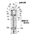
図5に詳細を示すように、歯部5の円筒状部分13の外周面には、歯15の歯幅方向一端側(径方向内方端側)が一体に形成されている。また、円筒状部分13の他端側(図4及び図5の右端側)の端面22と歯15の歯先面23とが面一となる(段差のない同一平面上であって、回転中心軸CLに直交する平面上に位置する)ように形成されている。また、歯15の歯幅方向他端側(径方向外方端側の外周面26)は、円板状部分14の外周面25に一致(回転中心軸CLを中心とする同一周面上に位置)するように形成されている。また、歯15と歯15との間の空間は、歯部5の径方向内方端側が円筒状部分13によって塞がれ、歯部5の径方向外方端側が径方向外方へ向かって開いている。また、円板状部分14の背面17(凹み21を除く部分)は、円筒状部分13の一端側の端面19と面一となる(段差のない同一平面上であって、回転中心軸CLに直交する平面上に位置する)ように形成されている。
As shown in detail in FIG. 5, the one end side in the tooth width direction (the radially inner end side) of the
また、図5に示すように、円板状部分14の一側面である歯底16を径方向内方へ延長した線24とウェブ4の第2の側面10とがほぼ一致(同一平面上に位置)するように、歯部5の円筒状部分13の内周面にはウェブ4の外周端が接続されている。このように形成することにより、射出成形樹脂フェースギヤ1は、射出成形後における径方向内方への樹脂の収縮(成形収縮)量が、ウェブ4を境にして、図5中の左側の部分と図5中の右側の部分とでほぼ等しくなる。その結果、射出成形樹脂フェースギヤ1は、図5に示すような歯15の倒れ、すなわち、歯先面23が基準位置よりも図5中右側の位置23’へ移動したり、また、歯先面23が基準位置よりも図5中左側の位置23”へ移動するようなことがなく、歯車精度を高精度に形作ることが可能になる。また、本実施形態に係る射出成形樹脂フェースギヤ1は、相手歯車との噛み合い位置精度が高精度になるため、高精度の回転伝達が可能になる。
Further, as shown in FIG. 5, the line 24 extending radially inward of the tooth bottom 16 that is one side surface of the disk-
なお、ウェブ4の外周端と円筒状部分13との接続位置は、ウェブ4の肉厚をt1とすると、ウェブ4の第2の側面10から円筒状部分13の一端側の端面19までの回転中心軸CLが延びる方向に沿った寸法がほぼt1であって、ウェブ4の第1の側面8から円筒状部分13の他端側の端面22までの回転中心軸CLが延びる方向に沿った寸法がほぼt1であるが、このような実施形態に限られるものではない。すなわち、ウェブ4の外周端と円筒状部分13との接続位置は、歯車精度を所望精度以内に維持できる限りにおいて、図4及び図5の態様よりも歯先面23寄りにずらしてもよく(例えば、円筒状部分13の内周面であって、且つ、回転中心軸CLに沿って右側方向へずらしてもよく)、また、図4及び図5の態様よりも円板状部分14の背面17寄りにずらしてもよい。そして、その結果、円板状部材14の一側面である歯底16を径方向内方へ延長した線24とウェブ4の第2の側面10とが、回転中心軸CLが延びる方向に沿ってずれて位置するようになってもよい。但し、いずれの態様を採用したとしても、ウェブ4の第2の側面10と円板状部分14の背面17は、回転中心軸CLに沿った方向(回転中心軸CLが延びる方向)にずれて位置している。そして、ウェブ4の第2の側面10が円板状部分14の背面17よりも歯15の歯先面23寄りに位置している。しかも、ウェブ4の外周端と円筒状部分13の接続部分の全体が、円筒状部分13の一端側の端面19と他端側の端面(一端側の端面19に対し、回転中心軸CLの延びる方向の反対側に位置する端面)22の間で、且つ、一端側の端面19(円板状部分14の背面17)と他端側の端面22に対して回転中心軸CLが延びる方向に沿ってずれて位置している。すなわち、ウェブ4の第1の側面8は、円筒状部分13の他端側の端面22と段差を生じるように一端側の端面19寄りに引っ込んでいる。また、ウェブ4の第2の側面10は、円筒状部分13の一端側の端面19と段差を生じるように他端側の端面22寄りに引っ込んでいる。
The connection position between the outer peripheral end of the web 4 and the
ここで、図4に示すように、歯部5の円筒状部分13の肉厚(t2)と円板状部分14の肉厚(t3)は、ウェブ4の肉厚(t1)とほぼ同一の厚さとなるように(成形上の寸法精度、キャビティ内への溶融樹脂の充填効率、射出成形後の冷却時間、要求される剛性等を考慮し、下限値を0.7・t1程度とし、上限値を1.3・t1程度の厚さとなるように)形成されている。
Here, as shown in FIG. 4, the thickness (t2) of the
また、図4及び図5に示すように、本実施形態の射出成形樹脂フェースギヤ1は、歯先面23の径方向内方への延長線上に、第1周方向リブ11aの先端面及び第2周方向リブ12aの先端面が位置するように形成されている。また、本実施形態の射出成形樹脂フェースギヤ1は、円板状部分14の背面17(一端側の端面19)の径方向内方への延長線上に、第1周方向リブ11bの先端面及び第2周方向リブ12bの先端面が位置するように形成されている。
As shown in FIGS. 4 and 5, the injection-molded
なお、本実施形態の射出成形樹脂フェースギヤ1は、第1周方向リブ11a,11bと第2周方向リブ12a,12bのうちの少なくとも一つについて、ウェブ4からの突出長さを変えたり(例えば、第1周方向リブ11bの先端面が円板状部分14の背面17の径方向内方への延長線上よりも内側(図4及び図5中における右側)に位置し、第2周方向リブ12bの先端面が円板状部分14の背面17の径方向内方への延長線上よりも外側(図4及び図5中における左側)に出っ張るように形成したり)、第1周方向リブ11a,11bと第2周方向リブ12a,12bの少なくとも一つについて、その肉厚を他部と異なるようにして、ウェブ4の面剛性及び全体の成形収縮のバランスをとるようにし、歯先面23の倒れを所望精度内に抑えるようにしてもよい。
The injection-molded
また、本実施形態の射出成形樹脂フェースギヤ1は、全体の成形収縮のバランスをとることができ、歯先面23の倒れを所望精度内に抑えることができる限りにおいて、円板状部分14の背面17と円筒状部分13の一端側の端面19の位置を回転中心軸CLが延びる方向に沿ってずらしたり、歯先面23と円筒状部分13の他端側の端面22の位置を回転中心軸CLが延びる方向に沿ってずらすようにしてもよい。
Further, the injection-molded
また、本実施形態の射出成形樹脂フェースギヤ1は、全体の成形収縮のバランスをとることができ、歯先面23の倒れを所望精度内に抑えることができる限りにおいて、円板状部分13の外周面25と歯15の外周面26を径方向に沿ってずらすようにしてもよい。
In addition, the injection-molded
また、本実施形態の射出成形樹脂フェースギヤ1は、全体の成形収縮のバランスをとることができ、歯先面23の倒れを所望精度内に抑えることができる限りにおいて、ボス3とウェブ4の接続位置を回転中心軸CLが延びる方向に沿ってずらしたり、ボス3の形状を適宜変更してもよい。
Further, the injection-molded
また、本実施形態の射出成形樹脂フェースギヤ1は、全体の成形収縮のバランスをとることができ、歯先面23の倒れを所望精度内に抑えることができる限りにおいて、ウェブ4の肉厚(t1)に対する歯部5の円筒状部分13の肉厚(t2)と円板状部分14の肉厚(t3)の比を、前述の下限値(0.7・t1)から上限値(1.3・t1)の範囲内で、t2=t1,t3=1.2・t1や、t2=t1,t3=0.8・t1のように、t1=t2=t3の関係を適宜変更してもよい。なお、円板状部分14の肉厚(t3)が厚すぎる場合には、歯面がうねってしまい、歯形精度が悪化し、また、円板状部分14の肉厚(t3)が薄すぎる場合には、ショートショットが生じて、歯形精度が悪化するため、このような成形不良に起因する歯形精度の悪化を生じないように、円板状部分14の肉厚が決定される。
Further, the injection molded
また、本実施形態の射出成形樹脂フェースギヤ1は、ウェブ4の肉厚をt1とした場合に、ウェブ4の第2の側面10から円筒状部分13の一端側の端面19までの回転中心軸CLが延びる方向に沿った寸法をほぼt1とし、ウェブ4の第1の側面8から円筒状部分13の他端側の端面22までの回転中心軸CLが延びる方向に沿った寸法をほぼt1とする態様を例示したが、これに限定されるものではなく、全体の成形収縮のバランスをとることができ、歯先面23の倒れを所望精度内に抑えることができる限りにおいて、円筒状部分13の一端側の端面19から円筒状部分13の他端側の端面22までの回転中心軸CLが延びる方向に沿った寸法を、歯15のモジュール等に応じて適宜変更してもよい。例えば、射出成形樹脂フェースギヤ1は、ウェブ4の肉厚をt1とした場合に、円筒状部分13の一端側の端面19から円筒状部分13の他端側の端面22までの回転中心軸CLが延びる方向に沿った寸法が3・t1に限られるものではなく、円筒状部分13の一端側の端面19から円筒状部分13の他端側の端面22までの回転中心軸CLが延びる方向に沿った寸法を歯15のモジュール等に応じて2.6・t1や2.8・t1等に適宜変更してもよい。
Further, the injection molded
図8は、本実施形態に係る射出成形樹脂フェースギヤ1の射出成形状態(射出成形金型30のキャビティ31内の溶融樹脂の流れ32)を模式的に示す図である。この図8に示すように、ゲート33からキャビティ31内に射出された溶融樹脂は、キャビティ31内のボスを形作る部分(3)側に向かう径方向内方への流れ32と、キャビティ31内の歯部を形作る部分(5)側に向かう径方向外方への流れ32とに分かれる。そして、キャビティ31内のウェブを形作る部分(4)を径方向外方へ向かって流動した溶融樹脂の流れ32は、キャビティ31内の歯部の円筒状部分を形作る部分(13)に流れ込み、キャビティ31内の歯部を形作る部分(5)内のガスを歯部の円板状部分を形作る部分(14)の裏面側外周端34に集めるように歯部を形作る部分(5)内を流動する。その結果、射出成形金型30から取り出された(射出成形後の)射出成形樹脂フェースギヤ1は、歯15にキャビティ内のガスに起因する成形不良を生じることがなく、歯15が高精度に成形される。
FIG. 8 is a diagram schematically showing an injection molding state (a
以上のように、本実施形態の射出成形樹脂フェースギヤ1は、射出成形後における樹脂の収縮(成形収縮)による歯15の倒れを抑えることができるため、歯車精度が高精度となり、回転伝達精度が向上する。
As described above, the injection-molded
なお、円板状部分14の背面17には、上記したように、円板状部分14の歯15に対応する部分と歯底16に対応する部分との射出成形後における樹脂の収縮(成形収縮)差によって凹み21が形成されるが、この樹脂の収縮差に起因する凹み21の他に、規則的又は不規則的な微小凹み(例えば、球の一部を切り取ったような形状の凹み)を形成するようにしてもよい。
In addition, on the
また、第1周方向リブ11a,11b及び第2周方向リブ12a,12b、円筒状部分13の内周面等には、図示はしないが、抜きこう配が適宜付けられている。
In addition, although not shown in the drawings, the first
本発明の射出成形樹脂フェースギヤは、直交する2軸間の動力伝達を可能にするために、駆動側の動力を被動側へ伝達する動力伝達機構に使用される他、直交する2軸間で高精度の回転伝達を行う必要があるセンサ等の回転伝達機構に広く使用することができる。 The injection-molded resin face gear of the present invention is used in a power transmission mechanism for transmitting driving power to a driven side in order to enable power transmission between two orthogonal axes, and between two orthogonal axes. It can be widely used in a rotation transmission mechanism such as a sensor that needs to perform rotation transmission with high accuracy.
1……射出成形樹脂フェースギヤ、2……軸穴、3……ボス、4……ウェブ、5……歯部、13……円筒状部分、14……円板状部分、15……歯、16……歯底、17……背面(他側面)、19……一端側の端面、22……他端側の端面、23……歯先面、25……円板状部分の外周面、26……歯の外周面、CL……回転中心軸
DESCRIPTION OF
Claims (2)
前記歯部は、前記ウェブの外周端に接続された円筒状部分と、この円筒状部分の一端側から径方向外方へ向けて形成された円板状部分と、この円板状部分の一側面が歯底になるように前記円筒状部分の外周側に等間隔で複数形成された歯と、を備えており、
前記ウェブの肉厚をt1とし、前記円筒状部分の肉厚をt2とし、前記円板状部分の肉厚をt3とした場合、0.7・t1≦t2≦1.3・t1、0.7・t1≦t3≦1.3・t1となるように、前記ウェブ、前記円筒状部分及び前記円板状部分が形成され、
前記ウェブと前記円筒状部分との接続部分の全体は、前記円筒状部分の前記一端側の端面とこの一端側の反対側である他端側の端面との間に位置し、且つ、前記円板状部分の他側面と前記円筒状部分の前記他端側の端面に対して回転中心軸が延びる方向に沿ってずれて位置する、
ことを特徴とする射出成形樹脂フェースギヤ。 An injection molded resin face gear comprising a boss, a disc-shaped web formed radially outward from the outer periphery of the boss, and a tooth portion formed on the outer peripheral end of the web. ,
The tooth portion includes a cylindrical portion connected to the outer peripheral end of the web, a disk-shaped portion formed radially outward from one end side of the cylindrical portion, and one of the disk-shaped portions. A plurality of teeth formed at equal intervals on the outer peripheral side of the cylindrical portion so that the side surface becomes the tooth bottom,
When the thickness of the web is t1, the thickness of the cylindrical portion is t2, and the thickness of the disc-shaped portion is t3, 0.7 · t1 ≦ t2 ≦ 1.3 · t1,. 7 · t1 ≦ t3 ≦ 1.3 · t1, the web, the cylindrical portion and the disc-shaped portion are formed,
The entire connecting portion between the web and the cylindrical portion is located between the end surface on the one end side of the cylindrical portion and the end surface on the other end side opposite to the one end side, and the circle The other side surface of the plate-like portion and the end surface on the other end side of the cylindrical portion are positioned so as to be shifted along the direction in which the rotation center axis extends.
An injection molded resin face gear characterized by that.
前記ウェブの肉厚をt1とすると、前記円筒状部分の前記一端側の端面から前記他端側の端面までの前記回転中心軸が延びる方向に沿った長さが3・t1であって、
前記ウェブと前記円筒状部分との接続部分から前記円筒状部分の前記一端側の端面までの前記回転中心軸が延びる方向に沿った長さがt1であり、
前記ウェブと前記円筒状部分との接続部分から前記円筒状部分の前記他端側の端面までの前記回転中心軸が延びる方向に沿った長さがt1である、
ことを特徴とする請求項1に記載の射出成形樹脂フェースギヤ。 The other side surface of the disc-shaped portion and the end surface on the one end side of the cylindrical portion are located on the same plane, and the outer peripheral surface of the disc-shaped portion and the outer peripheral surface of the teeth are on the same peripheral surface. The tooth tip surface of the tooth is located on the same plane as the end surface on the other end side of the cylindrical portion,
When the thickness of the web is t1, the length along the direction in which the rotation center axis extends from the end surface on the one end side to the end surface on the other end side of the cylindrical portion is 3 · t1,
The length along the direction in which the rotation center axis extends from the connection portion between the web and the cylindrical portion to the end surface on the one end side of the cylindrical portion is t 1.
The length along the direction in which the rotation center axis extends from the connection portion between the web and the cylindrical portion to the end surface on the other end side of the cylindrical portion is t 1.
The injection-molded resin face gear according to claim 1.
Priority Applications (1)
| Application Number | Priority Date | Filing Date | Title |
|---|---|---|---|
| JP2008035918A JP4854692B2 (en) | 2007-02-19 | 2008-02-18 | Injection molded resin face gear |
Applications Claiming Priority (3)
| Application Number | Priority Date | Filing Date | Title |
|---|---|---|---|
| JP2007037599 | 2007-02-19 | ||
| JP2007037599 | 2007-02-19 | ||
| JP2008035918A JP4854692B2 (en) | 2007-02-19 | 2008-02-18 | Injection molded resin face gear |
Publications (3)
| Publication Number | Publication Date |
|---|---|
| JP2008232432A JP2008232432A (en) | 2008-10-02 |
| JP2008232432A5 JP2008232432A5 (en) | 2010-09-16 |
| JP4854692B2 true JP4854692B2 (en) | 2012-01-18 |
Family
ID=39323064
Family Applications (1)
| Application Number | Title | Priority Date | Filing Date |
|---|---|---|---|
| JP2008035918A Active JP4854692B2 (en) | 2007-02-19 | 2008-02-18 | Injection molded resin face gear |
Country Status (4)
| Country | Link |
|---|---|
| US (2) | US8011263B2 (en) |
| EP (1) | EP1959167B1 (en) |
| JP (1) | JP4854692B2 (en) |
| CN (1) | CN101251180B (en) |
Families Citing this family (7)
| Publication number | Priority date | Publication date | Assignee | Title |
|---|---|---|---|---|
| JP5299967B2 (en) * | 2008-08-06 | 2013-09-25 | 株式会社エンプラス | Injection molded resin face gear |
| JP5284145B2 (en) * | 2009-03-12 | 2013-09-11 | タイガースポリマー株式会社 | Resin molded product with annular outer periphery |
| GB0906392D0 (en) * | 2009-04-15 | 2009-05-20 | Goodrich Actuation Systems Ltd | Thrust reverser actuator system |
| DE102009047519A1 (en) * | 2009-12-04 | 2011-06-09 | Robert Bosch Gmbh | Gearbox drive unit, particularly electrical auxiliary drive for motor vehicle, has rotatably arranged gearbox element, in which external teeth and annular collar are formed |
| JP6565537B2 (en) * | 2015-09-24 | 2019-08-28 | アイシン精機株式会社 | Gear transmission |
| JP6632921B2 (en) * | 2016-03-23 | 2020-01-22 | 株式会社エンプラス | Resin gear, resin gear injection molding method, resin toothed belt pulley, and resin rotating body |
| CN109114169A (en) * | 2018-10-08 | 2019-01-01 | 天津工业大学 | aviation spiral gear transmission system |
Family Cites Families (12)
| Publication number | Priority date | Publication date | Assignee | Title |
|---|---|---|---|---|
| JPS56148140A (en) * | 1980-04-21 | 1981-11-17 | Hitachi Ltd | System stabilization control device |
| US6343418B1 (en) * | 1997-11-20 | 2002-02-05 | Shimano Inc. | Spinning reel face gear manufacturing method |
| JP3926939B2 (en) * | 1998-12-09 | 2007-06-06 | 株式会社エンプラス | Synthetic resin molded gear |
| JP3688555B2 (en) * | 2000-05-30 | 2005-08-31 | 株式会社エンプラス | Resin gear, image forming apparatus, and resin rotation transmission means |
| JP2002223673A (en) * | 2001-02-01 | 2002-08-13 | Daiwa Seiko Inc | Face gear and method for producing the same |
| JP2002295643A (en) * | 2001-03-30 | 2002-10-09 | Fuji Photo Film Co Ltd | Transmission wheel for driving force |
| JP2004019774A (en) * | 2002-06-14 | 2004-01-22 | Enplas Corp | Injection molded resin face gear and finger driving mechanism for robot hand using the injection molded resin face gear |
| JP4190248B2 (en) * | 2002-10-09 | 2008-12-03 | 株式会社エンプラス | Clutch mechanism and finger driving mechanism of robot hand |
| JP4492842B2 (en) * | 2003-04-04 | 2010-06-30 | 株式会社エンプラス | Resin gear and resin rotational power transmission member |
| JP2004340160A (en) * | 2003-05-12 | 2004-12-02 | Polyplastics Co | Method of using resin-molded gear and gear train |
| JP2006070914A (en) * | 2004-08-31 | 2006-03-16 | Nidec Nissin Corp | Plastic gear |
| JP4618808B2 (en) * | 2006-09-14 | 2011-01-26 | 株式会社エンプラス | Resin face gear and injection mold for this resin face gear |
-
2008
- 2008-01-22 EP EP08150490A patent/EP1959167B1/en not_active Not-in-force
- 2008-01-30 US US12/011,881 patent/US8011263B2/en not_active Ceased
- 2008-02-18 JP JP2008035918A patent/JP4854692B2/en active Active
- 2008-02-18 CN CN2008100095383A patent/CN101251180B/en active Active
-
2013
- 2013-08-21 US US13/972,578 patent/USRE45516E1/en not_active Expired - Fee Related
Also Published As
| Publication number | Publication date |
|---|---|
| CN101251180A (en) | 2008-08-27 |
| US8011263B2 (en) | 2011-09-06 |
| EP1959167A2 (en) | 2008-08-20 |
| CN101251180B (en) | 2012-03-21 |
| EP1959167A3 (en) | 2008-08-27 |
| EP1959167B1 (en) | 2012-06-06 |
| JP2008232432A (en) | 2008-10-02 |
| US20090007711A1 (en) | 2009-01-08 |
| USRE45516E1 (en) | 2015-05-19 |
Similar Documents
| Publication | Publication Date | Title |
|---|---|---|
| JP4854692B2 (en) | Injection molded resin face gear | |
| JP5299967B2 (en) | Injection molded resin face gear | |
| JP4925292B2 (en) | Injection molded resin bevel gear | |
| JP5005422B2 (en) | Injection molding gear | |
| US8100026B2 (en) | Plastic injection-molded gear | |
| US11592099B2 (en) | Gear | |
| JP2006070914A (en) | Plastic gear | |
| JP6713830B2 (en) | Gear, gear transmission mechanism, and method of manufacturing gear | |
| JP4993725B2 (en) | Rotation transmission means and injection mold for rotation transmission means | |
| JP2001123986A (en) | Impeller for circumferential flow pump and molding method for it | |
| JP2003035355A (en) | Multi-stage gear made of resin and gear made of resin | |
| JP5904822B2 (en) | Resin gear and resin gear manufacturing method | |
| JP2006329243A (en) | Helical gear and its forming die | |
| JP2019195937A (en) | Gear, manufacturing method of the same, and injection mold used for gear manufacturing | |
| JP2006308107A (en) | Injection-molded plastic gear | |
| JP5948748B2 (en) | Variable guide vane, manufacturing method thereof, and supercharger for vehicle | |
| JP2008057665A (en) | Bearing | |
| JP2016075221A (en) | Gear pump | |
| JP3907888B2 (en) | Impeller for circumferential flow pump | |
| JPH09166199A (en) | Injection molded gear | |
| JPH0596564A (en) | Inorganic material gear | |
| JP4931147B2 (en) | Plastic face gear | |
| JP7084777B2 (en) | Blower impeller | |
| JP2006233871A (en) | Gear pump | |
| JP4860650B2 (en) | Synthetic resin molded product |
Legal Events
| Date | Code | Title | Description |
|---|---|---|---|
| A521 | Request for written amendment filed |
Free format text: JAPANESE INTERMEDIATE CODE: A523 Effective date: 20100729 |
|
| A621 | Written request for application examination |
Free format text: JAPANESE INTERMEDIATE CODE: A621 Effective date: 20100729 |
|
| TRDD | Decision of grant or rejection written | ||
| A01 | Written decision to grant a patent or to grant a registration (utility model) |
Free format text: JAPANESE INTERMEDIATE CODE: A01 Effective date: 20111024 |
|
| A01 | Written decision to grant a patent or to grant a registration (utility model) |
Free format text: JAPANESE INTERMEDIATE CODE: A01 |
|
| A977 | Report on retrieval |
Free format text: JAPANESE INTERMEDIATE CODE: A971007 Effective date: 20111027 |
|
| A61 | First payment of annual fees (during grant procedure) |
Free format text: JAPANESE INTERMEDIATE CODE: A61 Effective date: 20111025 |
|
| FPAY | Renewal fee payment (event date is renewal date of database) |
Free format text: PAYMENT UNTIL: 20141104 Year of fee payment: 3 |
|
| R150 | Certificate of patent or registration of utility model |
Ref document number: 4854692 Country of ref document: JP Free format text: JAPANESE INTERMEDIATE CODE: R150 Free format text: JAPANESE INTERMEDIATE CODE: R150 |
|
| R250 | Receipt of annual fees |
Free format text: JAPANESE INTERMEDIATE CODE: R250 |
|
| R250 | Receipt of annual fees |
Free format text: JAPANESE INTERMEDIATE CODE: R250 |
|
| R250 | Receipt of annual fees |
Free format text: JAPANESE INTERMEDIATE CODE: R250 |
|
| R250 | Receipt of annual fees |
Free format text: JAPANESE INTERMEDIATE CODE: R250 |
|
| R250 | Receipt of annual fees |
Free format text: JAPANESE INTERMEDIATE CODE: R250 |
|
| R250 | Receipt of annual fees |
Free format text: JAPANESE INTERMEDIATE CODE: R250 |
|
| R250 | Receipt of annual fees |
Free format text: JAPANESE INTERMEDIATE CODE: R250 |
|
| R250 | Receipt of annual fees |
Free format text: JAPANESE INTERMEDIATE CODE: R250 |
|
| R250 | Receipt of annual fees |
Free format text: JAPANESE INTERMEDIATE CODE: R250 |