EP1959167B1 - Injection-molded resin face gear - Google Patents
Injection-molded resin face gear Download PDFInfo
- Publication number
- EP1959167B1 EP1959167B1 EP08150490A EP08150490A EP1959167B1 EP 1959167 B1 EP1959167 B1 EP 1959167B1 EP 08150490 A EP08150490 A EP 08150490A EP 08150490 A EP08150490 A EP 08150490A EP 1959167 B1 EP1959167 B1 EP 1959167B1
- Authority
- EP
- European Patent Office
- Prior art keywords
- section
- web
- cylindrical section
- teeth
- injection
- Prior art date
- Legal status (The legal status is an assumption and is not a legal conclusion. Google has not performed a legal analysis and makes no representation as to the accuracy of the status listed.)
- Not-in-force
Links
Images


Classifications
-
- F—MECHANICAL ENGINEERING; LIGHTING; HEATING; WEAPONS; BLASTING
- F16—ENGINEERING ELEMENTS AND UNITS; GENERAL MEASURES FOR PRODUCING AND MAINTAINING EFFECTIVE FUNCTIONING OF MACHINES OR INSTALLATIONS; THERMAL INSULATION IN GENERAL
- F16H—GEARING
- F16H55/00—Elements with teeth or friction surfaces for conveying motion; Worms, pulleys or sheaves for gearing mechanisms
- F16H55/02—Toothed members; Worms
- F16H55/06—Use of materials; Use of treatments of toothed members or worms to affect their intrinsic material properties
-
- B—PERFORMING OPERATIONS; TRANSPORTING
- B29—WORKING OF PLASTICS; WORKING OF SUBSTANCES IN A PLASTIC STATE IN GENERAL
- B29C—SHAPING OR JOINING OF PLASTICS; SHAPING OF MATERIAL IN A PLASTIC STATE, NOT OTHERWISE PROVIDED FOR; AFTER-TREATMENT OF THE SHAPED PRODUCTS, e.g. REPAIRING
- B29C45/00—Injection moulding, i.e. forcing the required volume of moulding material through a nozzle into a closed mould; Apparatus therefor
- B29C45/0025—Preventing defects on the moulded article, e.g. weld lines, shrinkage marks
-
- F—MECHANICAL ENGINEERING; LIGHTING; HEATING; WEAPONS; BLASTING
- F16—ENGINEERING ELEMENTS AND UNITS; GENERAL MEASURES FOR PRODUCING AND MAINTAINING EFFECTIVE FUNCTIONING OF MACHINES OR INSTALLATIONS; THERMAL INSULATION IN GENERAL
- F16H—GEARING
- F16H55/00—Elements with teeth or friction surfaces for conveying motion; Worms, pulleys or sheaves for gearing mechanisms
- F16H55/02—Toothed members; Worms
- F16H55/17—Toothed wheels
-
- B—PERFORMING OPERATIONS; TRANSPORTING
- B29—WORKING OF PLASTICS; WORKING OF SUBSTANCES IN A PLASTIC STATE IN GENERAL
- B29L—INDEXING SCHEME ASSOCIATED WITH SUBCLASS B29C, RELATING TO PARTICULAR ARTICLES
- B29L2015/00—Gear wheels or similar articles with grooves or projections, e.g. control knobs
- B29L2015/003—Gears
-
- F—MECHANICAL ENGINEERING; LIGHTING; HEATING; WEAPONS; BLASTING
- F16—ENGINEERING ELEMENTS AND UNITS; GENERAL MEASURES FOR PRODUCING AND MAINTAINING EFFECTIVE FUNCTIONING OF MACHINES OR INSTALLATIONS; THERMAL INSULATION IN GENERAL
- F16H—GEARING
- F16H55/00—Elements with teeth or friction surfaces for conveying motion; Worms, pulleys or sheaves for gearing mechanisms
- F16H55/02—Toothed members; Worms
- F16H55/17—Toothed wheels
- F16H2055/173—Crown gears, i.e. gears have axially arranged teeth
-
- Y—GENERAL TAGGING OF NEW TECHNOLOGICAL DEVELOPMENTS; GENERAL TAGGING OF CROSS-SECTIONAL TECHNOLOGIES SPANNING OVER SEVERAL SECTIONS OF THE IPC; TECHNICAL SUBJECTS COVERED BY FORMER USPC CROSS-REFERENCE ART COLLECTIONS [XRACs] AND DIGESTS
- Y10—TECHNICAL SUBJECTS COVERED BY FORMER USPC
- Y10S—TECHNICAL SUBJECTS COVERED BY FORMER USPC CROSS-REFERENCE ART COLLECTIONS [XRACs] AND DIGESTS
- Y10S74/00—Machine element or mechanism
- Y10S74/10—Polymer digest - plastic gears
-
- Y—GENERAL TAGGING OF NEW TECHNOLOGICAL DEVELOPMENTS; GENERAL TAGGING OF CROSS-SECTIONAL TECHNOLOGIES SPANNING OVER SEVERAL SECTIONS OF THE IPC; TECHNICAL SUBJECTS COVERED BY FORMER USPC CROSS-REFERENCE ART COLLECTIONS [XRACs] AND DIGESTS
- Y10—TECHNICAL SUBJECTS COVERED BY FORMER USPC
- Y10T—TECHNICAL SUBJECTS COVERED BY FORMER US CLASSIFICATION
- Y10T74/00—Machine element or mechanism
- Y10T74/19—Gearing
- Y10T74/19642—Directly cooperating gears
- Y10T74/1966—Intersecting axes
-
- Y—GENERAL TAGGING OF NEW TECHNOLOGICAL DEVELOPMENTS; GENERAL TAGGING OF CROSS-SECTIONAL TECHNOLOGIES SPANNING OVER SEVERAL SECTIONS OF THE IPC; TECHNICAL SUBJECTS COVERED BY FORMER USPC CROSS-REFERENCE ART COLLECTIONS [XRACs] AND DIGESTS
- Y10—TECHNICAL SUBJECTS COVERED BY FORMER USPC
- Y10T—TECHNICAL SUBJECTS COVERED BY FORMER US CLASSIFICATION
- Y10T74/00—Machine element or mechanism
- Y10T74/19—Gearing
- Y10T74/19949—Teeth
Definitions
- the present invention relates to an injection-molded resin face gear used to allow power transmission and rotation transmission between two perpendicular axes.
- a face gear 100 such as that shown in Fig. 9 and Fig. 10 , using resin.
- a roughly disk-shaped web 102 is formed on an outer circumferential side of an axis section 101.
- a teeth section 103 is formed on an outer circumferential edge of the web 102.
- the teeth section 103 of the face gear 100 is formed such that teeth 104 of the teeth section 103 project towards one side surface 105 side.
- a plurality of teeth 104 are formed evenly spaced in a circumferential direction (refer to Patent Literature 1).
- Patent Literature 1 Japanese Patent Laid-open Publication No. 2002-223673 (refer, in particular, to paragraphs 0004 to 0005, and Fig. 3 and Fig 5 )
- the metal face gear 100 such as that shown in Fig. 9 and Fig. 10 are simply formed using resin
- shrinkage formation shrinkage
- the outer circumferential edge side of the web 102 collapses (curves and becomes deformed) such that a tooth crest 106 moves in a right-hand side direction in Fig. 10 .
- the teeth 104 collapse (the tooth crest 106 is displaced to a position indicated by 106').
- Gear accuracy may deteriorate, thereby making accurate and smooth rotation transmission difficult.
- the resin face gear includes a projecting section that projects from an outward radial direction side edge surface to increase a radial direction dimension of the outward radial direction side edge surface.
- the projecting section includes a teeth corresponding section formed on the outward radial direction side edge surface of the teeth.
- a parting line of a mold can be disposed near an outward radial direction side edge of teeth, even when a curved section is provided in the outward radial direction side edge.
- an object of the present invention is to provide an injection-molded resin face gear that can suppress deterioration of gear accuracy caused by shrinkage of resin material after injection-molding and allow accurate and smooth rotation transmission.
- the invention according to claim 1 is related to an injection-molded resin face gear.
- the injection-molded resin face gear includes a boss, a disk-shaped web, and a teeth section.
- the web is formed on an outer circumferential side of the boss in an outward radial direction.
- the teeth section is formed on an outer circumferential edge of the web.
- the teeth section includes a cylindrical section, a disk-shaped section, and a plurality of teeth.
- the cylindrical section is connected to the outer circumferential edge of the web.
- the disk-shaped section is formed on one end side of the cylindrical section in the outward radial direction.
- the teeth are formed evenly spaced on an outer circumferential side of the cylindrical section, such that one side surface of the disk-shaped section is a bottom land.
- the web, the cylindrical section, and the disk-shaped section are formed having almost the same thicknesses.
- An entire connection section between the web and the cylindrical section is positioned between an end surface on the one end side of the cylindrical section and an end surface on another end side that is an opposite side to the one end side.
- the entire connection portion is also positioned such as to be misaligned with another side surface of the disk-shaped section and an end surface on the other end side of the cylindrical section, along a direction in which a rotational center axis extends.
- the invention according to claim 2 is the injection-molded resin face gear according to claim 1, in which the other side surface of the disk-shaped section and the end surface on the one end side of the cylindrical section are positioned on a same plane.
- An outer peripheral surface of the disk-shaped section and an outer peripheral surface of the teeth are positioned on a same peripheral surface. Tooth crests of the teeth and the end surface on the other end side of the cylindrical section are positioned on a same plane.
- a length from the connection section between the web and the cylindrical section to the end surface on the one end side of the cylindrical section along the direction in which the rotational center axis extends is almost t1.
- a length from the connection section between the web and the cylindrical section to the end surface on the other end side of the cylindrical section along the direction in which the rotational center axis extends is almost t1.
- teeth collapse caused by shrinkage of resin material after injection-molding can be suppressed, and deterioration of gear accuracy can be suppressed.
- accurate and smooth rotation transmission can be achieved.
- Fig. 1 to Fig. 5 are diagrams of an injection-molded resin face gear 1 according to an embodiment of the invention.
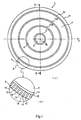
- Fig. 1A is a front view of the injection-molded resin face gear 1 (an injection-molded resin face gear 1 in Fig. 2 viewed from direction A).
- Fig. 1B is an enlarged view of portion B in Fig. 1A .
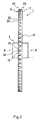
- Fig. 2 is a side view of the injection-molded resin face gear 1 (viewed from direction C in Fig. 1 ).
- Fig. 3 is a rear view of the injection-molded resin face gear 1 (the injection-molded resin face gear in Fig. 2 viewed from direction D).
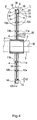
- Fig. 4 is a cross-sectional view taken along line E-E in Fig. 1 .
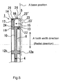
- Fig. 5 is an enlarged view of portion F in Fig. 4 .
- the injection-molded resin face gear 1 includes a cylindrical boss 3, a disk-shaped web 4, and a teeth section 5.
- the boss 3 has an axis hole 2.
- the web 4 is formed on an outer circumferential side of the boss 3 in an outward radial direction.
- the teeth section 5 is formed on an outer circumferential edge of the web 4.
- the injection-molded face gear 1 according to the embodiment is formed by injection molding, using resin material such as polyacetal, polyamide, polyphenylene sulfide, and polybutylene terephthalate.
- a rotation locking means such as a key groove or a spline groove (not shown), is formed on an inner circumferential surface of the axis hole in the boss 3.
- the rotation locking mechanism is engaged with a rotation axis 7 fitted into the axis hole 2, such as to integrally rotate with the rotation axis 7.
- the disk-shaped web 4 is formed on an outer peripheral surface of the boss, in a center section in a direction along a rotational center axis CL.
- the web 4 extends in the outward radial direction.
- An inner circumferential edge of the web 4 is connected to the outer peripheral surface of the boss 3.
- An outer circumferential edge of the web 4 is connected to the teeth section 5.
- First circumferential direction ribs 11a and second circumferential direction ribs 12a are formed on a first side surface 8 of the web 4.
- the first circumferential direction ribs 11a are formed near the boss 3 and are concentric with the boss 3.
- the second circumferential direction ribs 12a are positioned between the first circumferential direction ribs 11a and the teeth section 5, and are concentric with the first circumferential direction ribs 11a.
- the first circumferential direction ribs 11a and the second circumferential direction ribs 12a on the first side surface 8 are formed such as to project from the first side surface 8 in the shape of a ring.
- First circumferential direction ribs 11b and second circumferential direction ribs 12b are formed on a second side surface 10 of the web 4.
- the first circumferential direction ribs 11b are positioned in a location symmetrical with the first circumferential direction ribs 11a on the first side surface 8 in the radial direction.
- the second circumferential direction ribs 12b are positioned in a location symmetrical to the second circumferential direction ribs 12a in the radial direction.
- the first circumferential direction ribs 11b and the second circumferential direction ribs 12b on the second side surface 10 are formed such as to project from the second side surface 10 in the shape of a ring. Thicknesses of the first circumferential direction ribs 11a, the first circumferential direction ribs 11b, the second circumferential direction ribs 12a, and the second circumferential direction ribs 12a are almost the same as the thickness of the web 4 (when the thickness of the web 4 is t1, taking into consideration formation tolerance, (t1) ⁇ 0.3 ⁇ (t1)).
- the first circumferential direction ribs 11a and the second circumferential direction ribs 12a are formed on the first side surface 8 of the web 4 in this way.
- the first circumferential direction ribs 11b and the second circumferential direction ribs 12b are formed on the second side surface 10. As a result, surface rigidity of the web 4 can be enhanced.
- the teeth section 5 includes a ring-shaped, cylindrical section 13, a shoulder-shaped, disk-shaped section 14, and a plurality of teeth 15.
- the cylindrical section 13 is connected to the outer circumferential edge of the web 4.
- the disk-shaped section 14 is formed on one end side of the cylindrical section 13 (left-hand side in Fig. 4 and Fig. 5 ) in the outward radial direction.
- the teeth 15 are formed straddling the cylindrical section 13 and the disk-shaped section 14.
- a cross-sectional shape of the teeth section 5 in Fig. 4 and Fig. 5 is a rough L-shape, formed by the cylindrical section 13 and the disk-shaped section 14.
- the teeth 15 are formed on one side surface (right-hand side surface in Fig. 4 and Fig. 5 ) of the disk-shaped section 14 in the teeth section 5, evenly spaced along the circumferential direction.
- One side surface of the disk-shaped section 14 between each tooth 15 forms a bottom land 16.
- the teeth 15 are formed evenly spaced on the one side surface (right-hand side surface in Fig. 4 and Fig. 5 ) of the disk-shaped section 14 in the teeth section 5.
- An amount of shrinkage (formation shrinkage) in a direction along the rotational center axis CL after injection-molding differs between a section in which the teeth 15 are formed and a section corresponding with the bottom land 16.
- the section corresponding with the teeth 15 shrinks more than the section corresponding to the bottom land 16 in the rotational center axis CL direction.
- the section corresponding to the teeth 15 is slightly drawn inward ( ⁇ is about (1/100) to (2/100) ⁇ mm).
- the section that is drawn inward serves as a recess 21 that extends along a tooth width direction (radial direction) (refer to Fig. 6 and Fig. 7 ).
- one end side of the teeth 15 in the tooth width direction is integrally formed on the outer peripheral surface of the cylindrical section 13 of the teeth section 5.
- An end surface 22 of another end side of the cylindrical section 13 (the right end side in Fig. 4 and Fig. 5 ) and tooth crests 23 of the teeth 15 are flush (on a same plane with no level difference, and positioned on a plane perpendicular to the rotational center axis CL).
- Another end side of the teeth 15 in the tooth width direction matches an outer peripheral surface 25 of the disk-shaped section 14 (positioned on a same peripheral surface of which the rotational center axis CL is the center).
- An inward radial direction end side of the teeth section 5 in a space between each tooth 15 is blocked by the cylindrical section 13.
- An outward radial direction end side of the teeth section 5 is open in the outward radial direction.
- the back surface 17 (excluding the recess 21) of the disk-shaped section 14 is formed flush with an end surface 19 on one end side of the cylindrical section 13 (on a same plane with no level difference, and positioned on a plane perpendicular to the rotational center axis CL).
- the inner circumferential surface of the cylindrical section 13 in the teeth section 5 is connected to the outer peripheral surface of the web 4 such that a line 24 and the second side surface 10 of the web 4 almost match (positioned on a same plane).
- the line 24 is the bottom land 26, which is one side surface of the disk-shaped section 14, that is extended in the inward radial direction.
- a gear can be constructed to have high accuracy.
- a meshing position of the injection-molded resin face gear 1 according to the embodiment, at which the injection-molded resin face gear 1 meshes with a mating gear, is highly accurate. Therefore, a highly accurate rotation transmission can be achieved.
- a connection position between the outer circumferential edge of the web 4 and the cylindrical section 13 is as follows.
- a length from the second side surface 10 of the web 4 to the end surface 19 on one end side of the cylindrical section 13, along a direction in which the rotational center axis extends is almost t1.
- a length from the first side surface 8 of the web 4 to the end surface 22 on the other end of the cylindrical section 13, along the direction in which the rotational center axis extends, is almost t1.
- the embodiment is not limited thereto. In other words the connection position between the outer circumferential edge of the web 4 and the cylindrical section 13 can be shifted closer to the tooth crest 23 than that shown in Fig. 4 and Fig.
- the outer circumferential edge of the web 4 can be connected to the inner circumferential surface of the cylindrical section 13 and the connection position can be shifted to a right-hand direction along the rotational center axis CL).
- the connection position can be shifted closer to the back surface 17 to the disk-shaped section 14 that that in Fig. 4 and Fig. 5 .
- the second side surface 10 of the web 4 and the back surface 17 of the disk-shaped section 14 are positioned to be misaligned in the direction along the rotational center axis CL (the direction in which the rotational center axis CL extends).
- the second side surface 10 of the web 4 is positioned closer to the tooth crests 23 of the teeth 15 than the back surface 17 of the disk-shaped section 14.
- the entire connection section between the outer circumferential edge of the web 4 and the cylindrical section 13 is positioned between the end surface 19 on one end side of the cylindrical section 13 and the end surface 22 on the other end side (the end surface positioned opposite to the end surface 10 on the one end side, in the direction in which the rotational center axis CL extends).
- the entire connection section is misaligned with the end surface 19 on the one end side (the back surface 17 of the disk-shaped section 14) and the end surface 22 on the other end side, in the direction in which the rotational center axis CL extends.
- first side surface 8 of the web 4 is drawn inward towards the end surface 19 on one end side, such that a level difference with the end surface 22 on the one end side of the cylindrical section 13 is formed.
- the second side surface 10 of the web 4 is drawn inward towards the end surface 22 on the other end side, such that a level difference with the side surface 19 on the one end side of the cylindrical section 13 is formed.
- a thickness (t2) of the cylindrical section 13 of the teeth section 5 and a thickness (t3) of the disk-shaped section 14 are almost the same thickness as the thickness (t1) of the web 4 (taking into consideration formation length accuracy, efficiency with which the cavity is filled with molten resin, cooling period after injection molding, desired rigidity, and the like, the thickness has a lower threshold of about 0.7 ⁇ t1 and an upper threshold of about 1.3 ⁇ t1).
- the injection-molded resin face gear 1 according to the embodiment is formed such that the end surfaces of the first circumferential direction ribs 11a and the end surfaces of the second circumferential direction ribs 12a are positioned on a line extending in the inward radial direction of the tooth crests 23.
- the injection-molded resin face gear 1 according to the embodiment is also formed such that the end surfaces of the first circumferential direction ribs 11b and the end surfaces of the second circumferential direction ribs 12b are positioned on a line extending in the inward radial direction of the back surface 17 of the disk-shaped section 14 (the end surface 19 on the one end side).
- the injection-molded resin face gear 1 can be formed such that a projection length from the web 4 of at least one of the first circumferential ribs 11a, the first circumferential ribs 11b, the second circumferential ribs 12a, and the second circumferential ribs 12b is changed (for example, the end surface of the first circumferential ribs 11b is positioned further inward than the line extending in the inward radial direction of the back surface of the disk-shaped section 14 [the right-hand side in Fig. 4 and Fig.
- the injection-molded resin face gear 1 can be formed such that the surface rigidity of the web 4 and the overall formation shrinkage are balanced, thereby suppressing the collapse of the tooth crests 23 within the range of desired accuracy.
- the injection-molded resin face gear 1 according to the embodiment can be formed such that the positions of the back surface 17 of the disk-shaped section 14 and the end surface 19 of the one end side of the cylindrical section 13 are misaligned along the direction in which the rotational center axis CL extends, as long as the overall formation shrinkage can be balanced and the collapse of the tooth crests 23 can be suppressed within the range of desired accuracy.
- the injection-molded resin face gear 1 according to the embodiment can be formed such that the positions of the tooth crests 23 and the end surface 22 on the other end side of the cylindrical section 13 are misaligned along the direction in which the rotational center axis CL extends.
- the injection-molded resin face gear 1 according to the embodiment can be formed such that the outer peripheral surface 25 of the disk-shaped section 13 and the outer peripheral surface 26 of the teeth 15 are misaligned along the radial direction, as long as the overall formation shrinkage can be balanced and the collapse of the tooth crests 23 can be suppressed within the range of desired accuracy.
- the injection-molded resin face gear 1 according to the embodiment can be formed such that the connection position between the boss 3 and the web 4 is shifted along the direction in which the rotational center axis CL extends, as long as the overall formation shrinkage can be balanced and the collapse of the tooth crests 23 can be suppressed within the range of desired accuracy.
- the shape of the boss 3 can be changed accordingly.
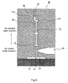
- Fig. 8 is a schematic diagram of an injection-molding state of the injection-molded resin face gear according to the embodiment of the present invention (a flow 32 of molten resin within a cavity 31 of an injection-molding mold 30).
- the molten resin discharged into the cavity 31 from a gate 33 is divided into a flow 32 that flows in an inward radial direction towards a section (3) within the cavity 31 forming the boss and a flow 32 that flows in an outward radial direction towards a section (5) within the cavity 31 forming the teeth section.
- the flow 32 of molten resin flowing through a section (4) within the cavity 31 forming the web in the outward radial direction flows into a section (13) within the cavity 31 forming the cylindrical section of the teeth section.
- the flow 32 of molten resin flows within the section (5) within the cavity 31 forming the teeth section such as to collect gas within the section (5) within the cavity 31 forming the teeth section in a back surface side outer circumferential end 34 of a section (14) forming the disk-shaped section of the teeth section.
- the injection-molded resin face gear 1 can suppress the collapse of the teeth 15 caused by the shrinkage (formation shrinkage) of resin after injection molding.
- the gear is highly accurate and rotation transmission accuracy is enhanced.
- the recess 21 is formed on the back surface 17 of the disk-shaped section 14, caused by a difference in shrinkage (formation shrinkage) after injection molding between the section corresponding to the teeth 15 of the disk-shaped section 14 and the section corresponding to the bottom land 16.
- regular or irregular miniscule recesses for example, a recess shaped as if a portion of a sphere has been cut out
- a draft (not shown) is attached as required to the inner circumferential surfaces and the like of the first circumferential ribs 11a, the first circumferential ribs 11b, the second circumferential ribs 12a, the second circumferential ribs 12b, and the cylindrical section 13
- the injection-molded resin face gear of the present invention can allow power transmission between two perpendicular axes. Therefore, in addition to being used in power transmission machines transmitting power from a driving side to a driven side, the injection-molded resin face gear can be widely used in rotation transmission machines, such as sensors, requiring highly accurate rotation transmission between two perpendicular axes.
Landscapes
- Engineering & Computer Science (AREA)
- General Engineering & Computer Science (AREA)
- Mechanical Engineering (AREA)
- Physics & Mathematics (AREA)
- Electromagnetism (AREA)
- Thermal Sciences (AREA)
- Manufacturing & Machinery (AREA)
- Gears, Cams (AREA)
- Moulds For Moulding Plastics Or The Like (AREA)
Description
- The present invention relates to an injection-molded resin face gear used to allow power transmission and rotation transmission between two perpendicular axes.
- In recent years, in technical fields related to power transmission devices using gears, resin gears are used being in place of metal gears to achieve quieter operation noise, reduced weight, and lower costs.
- Based on such technical background of recent years, there is discussion regarding forming a
face gear 100, such as that shown inFig. 9 and Fig. 10 , using resin. In theface gear 100 shown in the drawings, a roughly disk-shaped web 102 is formed on an outer circumferential side of anaxis section 101. Ateeth section 103 is formed on an outer circumferential edge of theweb 102. Theteeth section 103 of theface gear 100 is formed such thatteeth 104 of theteeth section 103 project towards oneside surface 105 side. A plurality ofteeth 104 are formed evenly spaced in a circumferential direction (refer to Patent Literature 1). - Patent Literature 1:
Japanese Patent Laid-open Publication No. 2002-223673 Fig. 3 andFig 5 ) - However, when the
metal face gear 100 such as that shown inFig. 9 and Fig. 10 are simply formed using resin, as a result of shrinkage (formation shrinkage) of resin material after injection-molding, the outer circumferential edge side of theweb 102 collapses (curves and becomes deformed) such that atooth crest 106 moves in a right-hand side direction inFig. 10 . Theteeth 104 collapse (thetooth crest 106 is displaced to a position indicated by 106'). Gear accuracy may deteriorate, thereby making accurate and smooth rotation transmission difficult. - The document
JP 2004-19774 claim 1, and is considered to be the closest prior art. - In the
document EP 1 900 495 A2 , which is published after the filing of the invention a resin face gear which is formed by injection molding is disclosed. The resin face gear includes a projecting section that projects from an outward radial direction side edge surface to increase a radial direction dimension of the outward radial direction side edge surface. The projecting section includes a teeth corresponding section formed on the outward radial direction side edge surface of the teeth. In the resin face gear, a parting line of a mold can be disposed near an outward radial direction side edge of teeth, even when a curved section is provided in the outward radial direction side edge. - Therefore, an object of the present invention is to provide an injection-molded resin face gear that can suppress deterioration of gear accuracy caused by shrinkage of resin material after injection-molding and allow accurate and smooth rotation transmission.
- The invention according to
claim 1 is related to an injection-molded resin face gear. The injection-molded resin face gear includes a boss, a disk-shaped web, and a teeth section. The web is formed on an outer circumferential side of the boss in an outward radial direction. The teeth section is formed on an outer circumferential edge of the web. In the invention, the teeth section includes a cylindrical section, a disk-shaped section, and a plurality of teeth. The cylindrical section is connected to the outer circumferential edge of the web. The disk-shaped section is formed on one end side of the cylindrical section in the outward radial direction. The teeth are formed evenly spaced on an outer circumferential side of the cylindrical section, such that one side surface of the disk-shaped section is a bottom land. The web, the cylindrical section, and the disk-shaped section are formed having almost the same thicknesses. An entire connection section between the web and the cylindrical section is positioned between an end surface on the one end side of the cylindrical section and an end surface on another end side that is an opposite side to the one end side. The entire connection portion is also positioned such as to be misaligned with another side surface of the disk-shaped section and an end surface on the other end side of the cylindrical section, along a direction in which a rotational center axis extends. - The invention according to
claim 2 is the injection-molded resin face gear according toclaim 1, in which the other side surface of the disk-shaped section and the end surface on the one end side of the cylindrical section are positioned on a same plane. An outer peripheral surface of the disk-shaped section and an outer peripheral surface of the teeth are positioned on a same peripheral surface. Tooth crests of the teeth and the end surface on the other end side of the cylindrical section are positioned on a same plane. When a thickness of the web is t1, a length from the end surface on the one end side of the cylindrical section to the end surface on the other end side along the direction in which the rotational center axis extends is almost 3·t1. A length from the connection section between the web and the cylindrical section to the end surface on the one end side of the cylindrical section along the direction in which the rotational center axis extends is almost t1. A length from the connection section between the web and the cylindrical section to the end surface on the other end side of the cylindrical section along the direction in which the rotational center axis extends is almost t1. - In the invention, teeth collapse caused by shrinkage of resin material after injection-molding can be suppressed, and deterioration of gear accuracy can be suppressed. As a result, accurate and smooth rotation transmission can be achieved.
-
-
Fig. 1A is a front view of an injection-molded resin face gear according to an embodiment of the present invention (an injection-molded resin face gear inFig. 2 viewed from direction A); -
Fig. 1B is an enlarged view of portion B inFig. 1A ; -
Fig. 2 is a side view of the injection-molded resin face gear according to the embodiment of the present invention (viewed from direction C inFig. 1 ); -
Fig. 3 is a rear view of the injection-molded resin face gear according to the embodiment of the present invention (the injection-molded resin face gear inFig. 2 viewed from direction D); -
Fig. 4 is a cross-sectional view of the injection-molded resin face gear according to the embodiment of the present invention, in which the injection-molded resin face gear inFig. 1 is taken along line E-E; -
Fig. 5 is an enlarged view of portion F inFig. 4 ; -
Fig. 6 is an enlarged view of portion G inFig. 3 ; -
Fig. 7 is a partially enlarged view of an outer circumferential edge of the injection-molded resin face gear according to the embodiment of the present invention, viewed from direction H inFig. 6 ; -
Fig. 8 is a schematic diagram of an injection-molding state of the injection-molded resin face gear according to the embodiment of the present invention (a flow of molten resin within a cavity of an injection-molding mold); -
Fig. 9 is a perspective view of a conventional face gear; and -
Fig. 10 is a vertical cross-sectional view of the conventional face gear. - Embodiments of the present invention will be described in detail, with reference to the drawings.
-
Fig. 1 to Fig. 5 are diagrams of an injection-moldedresin face gear 1 according to an embodiment of the invention.Fig. 1A is a front view of the injection-molded resin face gear 1 (an injection-moldedresin face gear 1 inFig. 2 viewed from direction A).Fig. 1B is an enlarged view of portion B inFig. 1A .Fig. 2 is a side view of the injection-molded resin face gear 1 (viewed from direction C inFig. 1 ).Fig. 3 is a rear view of the injection-molded resin face gear 1 (the injection-molded resin face gear inFig. 2 viewed from direction D).Fig. 4 is a cross-sectional view taken along line E-E inFig. 1 .Fig. 5 is an enlarged view of portion F inFig. 4 . - As shown in the diagrams, the injection-molded
resin face gear 1 according to the embodiment includes acylindrical boss 3, a disk-shapedweb 4, and ateeth section 5. Theboss 3 has anaxis hole 2. Theweb 4 is formed on an outer circumferential side of theboss 3 in an outward radial direction. Theteeth section 5 is formed on an outer circumferential edge of theweb 4. The injection-moldedface gear 1 according to the embodiment is formed by injection molding, using resin material such as polyacetal, polyamide, polyphenylene sulfide, and polybutylene terephthalate. - In such an injection-molded
resin face gear 1, a rotation locking means, such as a key groove or a spline groove (not shown), is formed on an inner circumferential surface of the axis hole in theboss 3. The rotation locking mechanism is engaged with arotation axis 7 fitted into theaxis hole 2, such as to integrally rotate with therotation axis 7. - The disk-shaped
web 4 is formed on an outer peripheral surface of the boss, in a center section in a direction along a rotational center axis CL. Theweb 4 extends in the outward radial direction. An inner circumferential edge of theweb 4 is connected to the outer peripheral surface of theboss 3. An outer circumferential edge of theweb 4 is connected to theteeth section 5. Firstcircumferential direction ribs 11a and secondcircumferential direction ribs 12a are formed on afirst side surface 8 of theweb 4. The firstcircumferential direction ribs 11a are formed near theboss 3 and are concentric with theboss 3. The secondcircumferential direction ribs 12a are positioned between the firstcircumferential direction ribs 11a and theteeth section 5, and are concentric with the firstcircumferential direction ribs 11a. The firstcircumferential direction ribs 11a and the secondcircumferential direction ribs 12a on thefirst side surface 8 are formed such as to project from thefirst side surface 8 in the shape of a ring. Firstcircumferential direction ribs 11b and secondcircumferential direction ribs 12b are formed on asecond side surface 10 of theweb 4. The firstcircumferential direction ribs 11b are positioned in a location symmetrical with the firstcircumferential direction ribs 11a on thefirst side surface 8 in the radial direction. The secondcircumferential direction ribs 12b are positioned in a location symmetrical to the secondcircumferential direction ribs 12a in the radial direction. The firstcircumferential direction ribs 11b and the secondcircumferential direction ribs 12b on thesecond side surface 10 are formed such as to project from thesecond side surface 10 in the shape of a ring. Thicknesses of the firstcircumferential direction ribs 11a, the firstcircumferential direction ribs 11b, the secondcircumferential direction ribs 12a, and the secondcircumferential direction ribs 12a are almost the same as the thickness of the web 4 (when the thickness of theweb 4 is t1, taking into consideration formation tolerance, (t1)±0.3·(t1)). The firstcircumferential direction ribs 11a and the secondcircumferential direction ribs 12a are formed on thefirst side surface 8 of theweb 4 in this way. The firstcircumferential direction ribs 11b and the secondcircumferential direction ribs 12b are formed on thesecond side surface 10. As a result, surface rigidity of theweb 4 can be enhanced. - The
teeth section 5 includes a ring-shaped,cylindrical section 13, a shoulder-shaped, disk-shapedsection 14, and a plurality ofteeth 15. Thecylindrical section 13 is connected to the outer circumferential edge of theweb 4. The disk-shapedsection 14 is formed on one end side of the cylindrical section 13 (left-hand side inFig. 4 andFig. 5 ) in the outward radial direction. Theteeth 15 are formed straddling thecylindrical section 13 and the disk-shapedsection 14. A cross-sectional shape of theteeth section 5 inFig. 4 andFig. 5 is a rough L-shape, formed by thecylindrical section 13 and the disk-shapedsection 14. - The
teeth 15 are formed on one side surface (right-hand side surface inFig. 4 andFig. 5 ) of the disk-shapedsection 14 in theteeth section 5, evenly spaced along the circumferential direction. One side surface of the disk-shapedsection 14 between eachtooth 15 forms abottom land 16. - The
teeth 15 are formed evenly spaced on the one side surface (right-hand side surface inFig. 4 andFig. 5 ) of the disk-shapedsection 14 in theteeth section 5. An amount of shrinkage (formation shrinkage) in a direction along the rotational center axis CL after injection-molding differs between a section in which theteeth 15 are formed and a section corresponding with thebottom land 16. In other words, on aback surface 17 side of the disk-shapedsection 14 in theteeth section 5, the section corresponding with theteeth 15 shrinks more than the section corresponding to thebottom land 16 in the rotational center axis CL direction. The section corresponding to theteeth 15 is slightly drawn inward (δ is about (1/100) to (2/100)·mm). The section that is drawn inward serves as arecess 21 that extends along a tooth width direction (radial direction) (refer toFig. 6 and Fig. 7 ). - As shown in detail in
Fig. 5 , one end side of theteeth 15 in the tooth width direction (inward radial direction end side) is integrally formed on the outer peripheral surface of thecylindrical section 13 of theteeth section 5. Anend surface 22 of another end side of the cylindrical section 13 (the right end side inFig. 4 andFig. 5 ) and tooth crests 23 of theteeth 15 are flush (on a same plane with no level difference, and positioned on a plane perpendicular to the rotational center axis CL). Another end side of theteeth 15 in the tooth width direction (an outerperipheral surface 26 on the outward radial direction end side) matches an outerperipheral surface 25 of the disk-shaped section 14 (positioned on a same peripheral surface of which the rotational center axis CL is the center). An inward radial direction end side of theteeth section 5 in a space between eachtooth 15 is blocked by thecylindrical section 13. An outward radial direction end side of theteeth section 5 is open in the outward radial direction. The back surface 17 (excluding the recess 21) of the disk-shapedsection 14 is formed flush with anend surface 19 on one end side of the cylindrical section 13 (on a same plane with no level difference, and positioned on a plane perpendicular to the rotational center axis CL). - As shown in
Fig. 5 , the inner circumferential surface of thecylindrical section 13 in theteeth section 5 is connected to the outer peripheral surface of theweb 4 such that a line 24 and thesecond side surface 10 of theweb 4 almost match (positioned on a same plane). The line 24 is thebottom land 26, which is one side surface of the disk-shapedsection 14, that is extended in the inward radial direction. As a result of this configuration, the shrinkage amount (formation shrinkage) of resin in the inward radial direction in the injection-moldedface gear 1 after injection molding is almost equal between a left-hand side section inFig. 5 and a right-hand side section inFig. 5 , with theweb 4 as a boundary. As a result, the collapse of theteeth 15, as shown inFig. 5 , does not occur. In other words, the tooth crests 23 do not move to a position 23' that is further to the right-hand side inFig. 5 than a base position, nor does the tooth crests 23 move to aposition 23" that is further to the left-hand side inFig. 5 than the base position. Therefore, a gear can be constructed to have high accuracy. A meshing position of the injection-moldedresin face gear 1 according to the embodiment, at which the injection-moldedresin face gear 1 meshes with a mating gear, is highly accurate. Therefore, a highly accurate rotation transmission can be achieved. - A connection position between the outer circumferential edge of the
web 4 and thecylindrical section 13 is as follows. When the thickness of theweb 4 is t1, a length from thesecond side surface 10 of theweb 4 to theend surface 19 on one end side of thecylindrical section 13, along a direction in which the rotational center axis extends, is almost t1. A length from thefirst side surface 8 of theweb 4 to theend surface 22 on the other end of thecylindrical section 13, along the direction in which the rotational center axis extends, is almost t1. However, the embodiment is not limited thereto. In other words the connection position between the outer circumferential edge of theweb 4 and thecylindrical section 13 can be shifted closer to thetooth crest 23 than that shown inFig. 4 andFig. 5 , as long as gear accuracy can be kept within a range of desired accuracy (for example, the outer circumferential edge of theweb 4 can be connected to the inner circumferential surface of thecylindrical section 13 and the connection position can be shifted to a right-hand direction along the rotational center axis CL). Alternatively, the connection position can be shifted closer to theback surface 17 to the disk-shapedsection 14 that that inFig. 4 andFig. 5 . However, regardless of the configuration to be used, thesecond side surface 10 of theweb 4 and theback surface 17 of the disk-shapedsection 14 are positioned to be misaligned in the direction along the rotational center axis CL (the direction in which the rotational center axis CL extends). Thesecond side surface 10 of theweb 4 is positioned closer to the tooth crests 23 of theteeth 15 than theback surface 17 of the disk-shapedsection 14. The entire connection section between the outer circumferential edge of theweb 4 and thecylindrical section 13 is positioned between theend surface 19 on one end side of thecylindrical section 13 and theend surface 22 on the other end side (the end surface positioned opposite to theend surface 10 on the one end side, in the direction in which the rotational center axis CL extends). In addition, the entire connection section is misaligned with theend surface 19 on the one end side (theback surface 17 of the disk-shaped section 14) and theend surface 22 on the other end side, in the direction in which the rotational center axis CL extends. In other words, thefirst side surface 8 of theweb 4 is drawn inward towards theend surface 19 on one end side, such that a level difference with theend surface 22 on the one end side of thecylindrical section 13 is formed. Thesecond side surface 10 of theweb 4 is drawn inward towards theend surface 22 on the other end side, such that a level difference with theside surface 19 on the one end side of thecylindrical section 13 is formed. - Here, as shown in
Fig. 4 , a thickness (t2) of thecylindrical section 13 of theteeth section 5 and a thickness (t3) of the disk-shapedsection 14 are almost the same thickness as the thickness (t1) of the web 4 (taking into consideration formation length accuracy, efficiency with which the cavity is filled with molten resin, cooling period after injection molding, desired rigidity, and the like, the thickness has a lower threshold of about 0.7·t1 and an upper threshold of about 1.3·t1). - As shown in
Fig. 4 andFig. 5 , the injection-moldedresin face gear 1 according to the embodiment is formed such that the end surfaces of the firstcircumferential direction ribs 11a and the end surfaces of the secondcircumferential direction ribs 12a are positioned on a line extending in the inward radial direction of the tooth crests 23. The injection-moldedresin face gear 1 according to the embodiment is also formed such that the end surfaces of the firstcircumferential direction ribs 11b and the end surfaces of the secondcircumferential direction ribs 12b are positioned on a line extending in the inward radial direction of theback surface 17 of the disk-shaped section 14 (theend surface 19 on the one end side). - The injection-molded
resin face gear 1 according to the embodiment can be formed such that a projection length from theweb 4 of at least one of the firstcircumferential ribs 11a, the firstcircumferential ribs 11b, the secondcircumferential ribs 12a, and the secondcircumferential ribs 12b is changed (for example, the end surface of the firstcircumferential ribs 11b is positioned further inward than the line extending in the inward radial direction of the back surface of the disk-shaped section 14 [the right-hand side inFig. 4 andFig. 5 ] and the end surface of the secondcircumferential ribs 12b is formed to project further outward than the line extending in the outward radial direction of theback surface 17 of the disk-shaped section 14 [the left-hand side inFig. 4 andFig. 5 ]), and the thickness of at least one of the firstcircumferential ribs 11a, the firstcircumferential ribs 11b, the secondcircumferential ribs 12a, and the secondcircumferential ribs 12b differs from the other sections. Therefore, the injection-moldedresin face gear 1 can be formed such that the surface rigidity of theweb 4 and the overall formation shrinkage are balanced, thereby suppressing the collapse of the tooth crests 23 within the range of desired accuracy. - The injection-molded
resin face gear 1 according to the embodiment can be formed such that the positions of theback surface 17 of the disk-shapedsection 14 and theend surface 19 of the one end side of thecylindrical section 13 are misaligned along the direction in which the rotational center axis CL extends, as long as the overall formation shrinkage can be balanced and the collapse of the tooth crests 23 can be suppressed within the range of desired accuracy.
Alternatively, the injection-moldedresin face gear 1 according to the embodiment can be formed such that the positions of the tooth crests 23 and theend surface 22 on the other end side of thecylindrical section 13 are misaligned along the direction in which the rotational center axis CL extends. - The injection-molded
resin face gear 1 according to the embodiment can be formed such that the outerperipheral surface 25 of the disk-shapedsection 13 and the outerperipheral surface 26 of theteeth 15 are misaligned along the radial direction, as long as the overall formation shrinkage can be balanced and the collapse of the tooth crests 23 can be suppressed within the range of desired accuracy. - The injection-molded
resin face gear 1 according to the embodiment can be formed such that the connection position between theboss 3 and theweb 4 is shifted along the direction in which the rotational center axis CL extends, as long as the overall formation shrinkage can be balanced and the collapse of the tooth crests 23 can be suppressed within the range of desired accuracy. Alternatively, the shape of theboss 3 can be changed accordingly. -
Fig. 8 is a schematic diagram of an injection-molding state of the injection-molded resin face gear according to the embodiment of the present invention (aflow 32 of molten resin within acavity 31 of an injection-molding mold 30). As shown inFig. 8 , the molten resin discharged into thecavity 31 from agate 33 is divided into aflow 32 that flows in an inward radial direction towards a section (3) within thecavity 31 forming the boss and aflow 32 that flows in an outward radial direction towards a section (5) within thecavity 31 forming the teeth section. Theflow 32 of molten resin flowing through a section (4) within thecavity 31 forming the web in the outward radial direction flows into a section (13) within thecavity 31 forming the cylindrical section of the teeth section. Theflow 32 of molten resin flows within the section (5) within thecavity 31 forming the teeth section such as to collect gas within the section (5) within thecavity 31 forming the teeth section in a back surface side outercircumferential end 34 of a section (14) forming the disk-shaped section of the teeth section. As a result, when the injection-molded resin face gear 1 (after injection molding) is removed from the injection-molding mold 30, theteeth 15 are formed with high accuracy, without formation defects in theteeth 15 caused by gas within the cavity. - As described above, the injection-molded
resin face gear 1 according to the embodiment can suppress the collapse of theteeth 15 caused by the shrinkage (formation shrinkage) of resin after injection molding. As a result, the gear is highly accurate and rotation transmission accuracy is enhanced. - As described above, the
recess 21 is formed on theback surface 17 of the disk-shapedsection 14, caused by a difference in shrinkage (formation shrinkage) after injection molding between the section corresponding to theteeth 15 of the disk-shapedsection 14 and the section corresponding to thebottom land 16. However, other than therecess 21 caused by the difference in shrinkage of the resin, regular or irregular miniscule recesses (for example, a recess shaped as if a portion of a sphere has been cut out) can also be formed. - A draft (not shown) is attached as required to the inner circumferential surfaces and the like of the first
circumferential ribs 11a, the firstcircumferential ribs 11b, the secondcircumferential ribs 12a, the secondcircumferential ribs 12b, and thecylindrical section 13 - The injection-molded resin face gear of the present invention can allow power transmission between two perpendicular axes. Therefore, in addition to being used in power transmission machines transmitting power from a driving side to a driven side, the injection-molded resin face gear can be widely used in rotation transmission machines, such as sensors, requiring highly accurate rotation transmission between two perpendicular axes.
Claims (2)
- An injection-molded resin face gear (1) including a boss (3), a disk-shaped web (4) formed on an outer circumferential side of the boss (3) in an outward radial direction, and a teeth section (5) formed on an outer peripheral edge of the web (4), wherein:the teeth section (5) includes a cylindrical section (13) connected to the outer peripheral edge of the web (4), characterized in that a disk-shaped section (14) is formed on one end side of the cylindrical section (13) in the outward radial direction, and a plurality of teeth (15) are formed evenly spaced on an outer circumferential side of the cylindrical section (13) such that one side surface of the disk-shaped section (14) is a bottom land (16);when a thickness of the web (4) is t1, the cylindrical section (13) and the disk-shaped section (14) have a thickness of 0.7t1 to 1.3t1;an entire connection section between the web (4) and the cylindrical section (13) is positioned between an end surface (19) on the one end side of the cylindrical section (13) and an end surface (22) on another end side that is an opposite side to the one end side, and is positioned such as to be misaligned with another side surface of the disk-shaped section (14) and an end surface (22) on the other end side of the cylindrical section (13), along a direction in which a rotational center axis (CL) extends;whereintooth crests (23) of the teeth (15) and the end surface (22) on the other end side of the cylindrical section (13) are positioned on a same plane.
- The injection-molded resin face gear (1) according to claim 1, wherein:the other side surface of the disk-shaped section (14) and the end surface (19) on the one end side of the cylindrical section (13) are positioned on a same plane, an outer peripheral surface of the disk-shaped section (14) and an outer peripheral surface of the teeth (15) are positioned on a same peripheral surface;when a thickness of the web (4) is t1, a length from the end surface (19) on the one end side of the cylindrical section (13) to the end surface (22) on the other end side along the direction in which the rotational center axis (CL) extends is almost 3 t1;a length from the connection section between the web (4) and the cylindrical section (13) to the end surface (19) on the one end side of the cylindrical section (13) along the direction in which the rotational center axis (CL) extends is almost t1; anda length from the connection section between the web (4) and the cylindrical section (13) to the end surface (22) on the other end side of the cylindrical section (13) along the direction in which the rotational center axis (CL) extends is approximately t1.
Applications Claiming Priority (1)
| Application Number | Priority Date | Filing Date | Title |
|---|---|---|---|
| JP2007037599 | 2007-02-19 |
Publications (3)
| Publication Number | Publication Date |
|---|---|
| EP1959167A2 EP1959167A2 (en) | 2008-08-20 |
| EP1959167A3 EP1959167A3 (en) | 2008-08-27 |
| EP1959167B1 true EP1959167B1 (en) | 2012-06-06 |
Family
ID=39323064
Family Applications (1)
| Application Number | Title | Priority Date | Filing Date |
|---|---|---|---|
| EP08150490A Not-in-force EP1959167B1 (en) | 2007-02-19 | 2008-01-22 | Injection-molded resin face gear |
Country Status (4)
| Country | Link |
|---|---|
| US (2) | US8011263B2 (en) |
| EP (1) | EP1959167B1 (en) |
| JP (1) | JP4854692B2 (en) |
| CN (1) | CN101251180B (en) |
Families Citing this family (7)
| Publication number | Priority date | Publication date | Assignee | Title |
|---|---|---|---|---|
| JP5299967B2 (en) * | 2008-08-06 | 2013-09-25 | 株式会社エンプラス | Injection molded resin face gear |
| JP5284145B2 (en) * | 2009-03-12 | 2013-09-11 | タイガースポリマー株式会社 | Resin molded product with annular outer periphery |
| GB0906392D0 (en) * | 2009-04-15 | 2009-05-20 | Goodrich Actuation Systems Ltd | Thrust reverser actuator system |
| DE102009047519A1 (en) * | 2009-12-04 | 2011-06-09 | Robert Bosch Gmbh | Gearbox drive unit, particularly electrical auxiliary drive for motor vehicle, has rotatably arranged gearbox element, in which external teeth and annular collar are formed |
| JP6565537B2 (en) * | 2015-09-24 | 2019-08-28 | アイシン精機株式会社 | Gear transmission |
| JP6632921B2 (en) * | 2016-03-23 | 2020-01-22 | 株式会社エンプラス | Resin gear, resin gear injection molding method, resin toothed belt pulley, and resin rotating body |
| CN109114169A (en) * | 2018-10-08 | 2019-01-01 | 天津工业大学 | aviation spiral gear transmission system |
Family Cites Families (12)
| Publication number | Priority date | Publication date | Assignee | Title |
|---|---|---|---|---|
| JPS56148140A (en) * | 1980-04-21 | 1981-11-17 | Hitachi Ltd | System stabilization control device |
| US6343418B1 (en) * | 1997-11-20 | 2002-02-05 | Shimano Inc. | Spinning reel face gear manufacturing method |
| JP3926939B2 (en) * | 1998-12-09 | 2007-06-06 | 株式会社エンプラス | Synthetic resin molded gear |
| JP3688555B2 (en) * | 2000-05-30 | 2005-08-31 | 株式会社エンプラス | Resin gear, image forming apparatus, and resin rotation transmission means |
| JP2002223673A (en) | 2001-02-01 | 2002-08-13 | Daiwa Seiko Inc | Face gear and method for producing the same |
| JP2002295643A (en) * | 2001-03-30 | 2002-10-09 | Fuji Photo Film Co Ltd | Transmission wheel for driving force |
| JP2004019774A (en) * | 2002-06-14 | 2004-01-22 | Enplas Corp | Injection molded resin face gear and finger driving mechanism for robot hand using the injection molded resin face gear |
| JP4190248B2 (en) * | 2002-10-09 | 2008-12-03 | 株式会社エンプラス | Clutch mechanism and finger driving mechanism of robot hand |
| JP4492842B2 (en) * | 2003-04-04 | 2010-06-30 | 株式会社エンプラス | Resin gear and resin rotational power transmission member |
| JP2004340160A (en) * | 2003-05-12 | 2004-12-02 | Polyplastics Co | Method of using resin-molded gear and gear train |
| JP2006070914A (en) * | 2004-08-31 | 2006-03-16 | Nidec Nissin Corp | Plastic gear |
| JP4618808B2 (en) * | 2006-09-14 | 2011-01-26 | 株式会社エンプラス | Resin face gear and injection mold for this resin face gear |
-
2008
- 2008-01-22 EP EP08150490A patent/EP1959167B1/en not_active Not-in-force
- 2008-01-30 US US12/011,881 patent/US8011263B2/en not_active Ceased
- 2008-02-18 CN CN2008100095383A patent/CN101251180B/en active Active
- 2008-02-18 JP JP2008035918A patent/JP4854692B2/en not_active Expired - Fee Related
-
2013
- 2013-08-21 US US13/972,578 patent/USRE45516E1/en not_active Expired - Fee Related
Also Published As
| Publication number | Publication date |
|---|---|
| CN101251180B (en) | 2012-03-21 |
| JP4854692B2 (en) | 2012-01-18 |
| US8011263B2 (en) | 2011-09-06 |
| CN101251180A (en) | 2008-08-27 |
| EP1959167A3 (en) | 2008-08-27 |
| EP1959167A2 (en) | 2008-08-20 |
| USRE45516E1 (en) | 2015-05-19 |
| JP2008232432A (en) | 2008-10-02 |
| US20090007711A1 (en) | 2009-01-08 |
Similar Documents
| Publication | Publication Date | Title |
|---|---|---|
| USRE45516E1 (en) | Injection-molded resin face gear | |
| JP5005422B2 (en) | Injection molding gear | |
| US7698964B2 (en) | Gear | |
| US8100026B2 (en) | Plastic injection-molded gear | |
| US9663138B2 (en) | Worm wheel and electric power steering apparatus | |
| US8240227B2 (en) | Injection-molded resin face gear | |
| US20060053917A1 (en) | Plastic gear | |
| JP5008197B2 (en) | Injection molding resin gear molding method and injection molding resin gear | |
| EP1939492B1 (en) | Injection-molded resin bevel gear | |
| JP2002021978A (en) | Resin-made gear and metal molding structure | |
| JP2008069867A (en) | Resin face gear and its injection molding die | |
| US11592099B2 (en) | Gear | |
| JP2010025239A (en) | Gear and method for manufacturing the same | |
| JP2003035355A (en) | Multi-stage gear made of resin and gear made of resin | |
| JP2002347081A (en) | Annular resin molding | |
| JP4297926B2 (en) | Injection molded plastic gear | |
| JP2008057665A (en) | Bearing | |
| CN101270803A (en) | Resin double-helical gear | |
| JP3718812B2 (en) | Resin molded gear | |
| JP2005291323A (en) | Resin gear | |
| JP2016183764A (en) | Composite gear and manufacturing method thereof |
Legal Events
| Date | Code | Title | Description |
|---|---|---|---|
| PUAI | Public reference made under article 153(3) epc to a published international application that has entered the european phase |
Free format text: ORIGINAL CODE: 0009012 |
|
| PUAL | Search report despatched |
Free format text: ORIGINAL CODE: 0009013 |
|
| AK | Designated contracting states |
Kind code of ref document: A2 Designated state(s): AT BE BG CH CY CZ DE DK EE ES FI FR GB GR HR HU IE IS IT LI LT LU LV MC MT NL NO PL PT RO SE SI SK TR |
|
| AX | Request for extension of the european patent |
Extension state: AL BA MK RS |
|
| AK | Designated contracting states |
Kind code of ref document: A3 Designated state(s): AT BE BG CH CY CZ DE DK EE ES FI FR GB GR HR HU IE IS IT LI LT LU LV MC MT NL NO PL PT RO SE SI SK TR |
|
| AX | Request for extension of the european patent |
Extension state: AL BA MK RS |
|
| RIC1 | Information provided on ipc code assigned before grant |
Ipc: F16H 55/06 20060101ALI20080721BHEP Ipc: F16H 55/22 20060101AFI20080506BHEP |
|
| 17P | Request for examination filed |
Effective date: 20081217 |
|
| 17Q | First examination report despatched |
Effective date: 20090303 |
|
| AKX | Designation fees paid |
Designated state(s): AT BE BG CH CY CZ DE DK EE ES FI FR GB GR HR HU IE IS IT LI LT LU LV MC MT NL NO PL PT RO SE SI SK TR |
|
| REG | Reference to a national code |
Ref country code: DE Ref legal event code: R079 Ref document number: 602008016125 Country of ref document: DE Free format text: PREVIOUS MAIN CLASS: F16H0055220000 Ipc: F16H0055170000 |
|
| GRAP | Despatch of communication of intention to grant a patent |
Free format text: ORIGINAL CODE: EPIDOSNIGR1 |
|
| RIC1 | Information provided on ipc code assigned before grant |
Ipc: F16H 55/06 20060101ALI20111219BHEP Ipc: F16H 55/22 20060101ALI20111219BHEP Ipc: B29C 45/00 20060101ALI20111219BHEP Ipc: F16H 55/17 20060101AFI20111219BHEP |
|
| GRAS | Grant fee paid |
Free format text: ORIGINAL CODE: EPIDOSNIGR3 |
|
| GRAA | (expected) grant |
Free format text: ORIGINAL CODE: 0009210 |
|
| AK | Designated contracting states |
Kind code of ref document: B1 Designated state(s): AT BE BG CH CY CZ DE DK EE ES FI FR GB GR HR HU IE IS IT LI LT LU LV MC MT NL NO PL PT RO SE SI SK TR |
|
| REG | Reference to a national code |
Ref country code: GB Ref legal event code: FG4D |
|
| REG | Reference to a national code |
Ref country code: AT Ref legal event code: REF Ref document number: 561190 Country of ref document: AT Kind code of ref document: T Effective date: 20120615 Ref country code: CH Ref legal event code: EP |
|
| REG | Reference to a national code |
Ref country code: IE Ref legal event code: FG4D |
|
| REG | Reference to a national code |
Ref country code: DE Ref legal event code: R096 Ref document number: 602008016125 Country of ref document: DE Effective date: 20120809 |
|
| REG | Reference to a national code |
Ref country code: NL Ref legal event code: VDEP Effective date: 20120606 |
|
| PG25 | Lapsed in a contracting state [announced via postgrant information from national office to epo] |
Ref country code: LT Free format text: LAPSE BECAUSE OF FAILURE TO SUBMIT A TRANSLATION OF THE DESCRIPTION OR TO PAY THE FEE WITHIN THE PRESCRIBED TIME-LIMIT Effective date: 20120606 Ref country code: CY Free format text: LAPSE BECAUSE OF FAILURE TO SUBMIT A TRANSLATION OF THE DESCRIPTION OR TO PAY THE FEE WITHIN THE PRESCRIBED TIME-LIMIT Effective date: 20120606 Ref country code: SE Free format text: LAPSE BECAUSE OF FAILURE TO SUBMIT A TRANSLATION OF THE DESCRIPTION OR TO PAY THE FEE WITHIN THE PRESCRIBED TIME-LIMIT Effective date: 20120606 Ref country code: FI Free format text: LAPSE BECAUSE OF FAILURE TO SUBMIT A TRANSLATION OF THE DESCRIPTION OR TO PAY THE FEE WITHIN THE PRESCRIBED TIME-LIMIT Effective date: 20120606 Ref country code: NO Free format text: LAPSE BECAUSE OF FAILURE TO SUBMIT A TRANSLATION OF THE DESCRIPTION OR TO PAY THE FEE WITHIN THE PRESCRIBED TIME-LIMIT Effective date: 20120906 |
|
| REG | Reference to a national code |
Ref country code: AT Ref legal event code: MK05 Ref document number: 561190 Country of ref document: AT Kind code of ref document: T Effective date: 20120606 |
|
| REG | Reference to a national code |
Ref country code: LT Ref legal event code: MG4D Effective date: 20120606 |
|
| PG25 | Lapsed in a contracting state [announced via postgrant information from national office to epo] |
Ref country code: SI Free format text: LAPSE BECAUSE OF FAILURE TO SUBMIT A TRANSLATION OF THE DESCRIPTION OR TO PAY THE FEE WITHIN THE PRESCRIBED TIME-LIMIT Effective date: 20120606 Ref country code: LV Free format text: LAPSE BECAUSE OF FAILURE TO SUBMIT A TRANSLATION OF THE DESCRIPTION OR TO PAY THE FEE WITHIN THE PRESCRIBED TIME-LIMIT Effective date: 20120606 Ref country code: GR Free format text: LAPSE BECAUSE OF FAILURE TO SUBMIT A TRANSLATION OF THE DESCRIPTION OR TO PAY THE FEE WITHIN THE PRESCRIBED TIME-LIMIT Effective date: 20120907 Ref country code: HR Free format text: LAPSE BECAUSE OF FAILURE TO SUBMIT A TRANSLATION OF THE DESCRIPTION OR TO PAY THE FEE WITHIN THE PRESCRIBED TIME-LIMIT Effective date: 20120606 |
|
| PG25 | Lapsed in a contracting state [announced via postgrant information from national office to epo] |
Ref country code: CZ Free format text: LAPSE BECAUSE OF FAILURE TO SUBMIT A TRANSLATION OF THE DESCRIPTION OR TO PAY THE FEE WITHIN THE PRESCRIBED TIME-LIMIT Effective date: 20120606 Ref country code: SK Free format text: LAPSE BECAUSE OF FAILURE TO SUBMIT A TRANSLATION OF THE DESCRIPTION OR TO PAY THE FEE WITHIN THE PRESCRIBED TIME-LIMIT Effective date: 20120606 Ref country code: IS Free format text: LAPSE BECAUSE OF FAILURE TO SUBMIT A TRANSLATION OF THE DESCRIPTION OR TO PAY THE FEE WITHIN THE PRESCRIBED TIME-LIMIT Effective date: 20121006 Ref country code: NL Free format text: LAPSE BECAUSE OF FAILURE TO SUBMIT A TRANSLATION OF THE DESCRIPTION OR TO PAY THE FEE WITHIN THE PRESCRIBED TIME-LIMIT Effective date: 20120606 Ref country code: EE Free format text: LAPSE BECAUSE OF FAILURE TO SUBMIT A TRANSLATION OF THE DESCRIPTION OR TO PAY THE FEE WITHIN THE PRESCRIBED TIME-LIMIT Effective date: 20120606 Ref country code: RO Free format text: LAPSE BECAUSE OF FAILURE TO SUBMIT A TRANSLATION OF THE DESCRIPTION OR TO PAY THE FEE WITHIN THE PRESCRIBED TIME-LIMIT Effective date: 20120606 Ref country code: BE Free format text: LAPSE BECAUSE OF FAILURE TO SUBMIT A TRANSLATION OF THE DESCRIPTION OR TO PAY THE FEE WITHIN THE PRESCRIBED TIME-LIMIT Effective date: 20120606 Ref country code: AT Free format text: LAPSE BECAUSE OF FAILURE TO SUBMIT A TRANSLATION OF THE DESCRIPTION OR TO PAY THE FEE WITHIN THE PRESCRIBED TIME-LIMIT Effective date: 20120606 |
|
| PG25 | Lapsed in a contracting state [announced via postgrant information from national office to epo] |
Ref country code: PT Free format text: LAPSE BECAUSE OF FAILURE TO SUBMIT A TRANSLATION OF THE DESCRIPTION OR TO PAY THE FEE WITHIN THE PRESCRIBED TIME-LIMIT Effective date: 20121008 Ref country code: PL Free format text: LAPSE BECAUSE OF FAILURE TO SUBMIT A TRANSLATION OF THE DESCRIPTION OR TO PAY THE FEE WITHIN THE PRESCRIBED TIME-LIMIT Effective date: 20120606 Ref country code: IT Free format text: LAPSE BECAUSE OF FAILURE TO SUBMIT A TRANSLATION OF THE DESCRIPTION OR TO PAY THE FEE WITHIN THE PRESCRIBED TIME-LIMIT Effective date: 20120606 |
|
| PLBE | No opposition filed within time limit |
Free format text: ORIGINAL CODE: 0009261 |
|
| STAA | Information on the status of an ep patent application or granted ep patent |
Free format text: STATUS: NO OPPOSITION FILED WITHIN TIME LIMIT |
|
| PG25 | Lapsed in a contracting state [announced via postgrant information from national office to epo] |
Ref country code: ES Free format text: LAPSE BECAUSE OF FAILURE TO SUBMIT A TRANSLATION OF THE DESCRIPTION OR TO PAY THE FEE WITHIN THE PRESCRIBED TIME-LIMIT Effective date: 20120917 Ref country code: DK Free format text: LAPSE BECAUSE OF FAILURE TO SUBMIT A TRANSLATION OF THE DESCRIPTION OR TO PAY THE FEE WITHIN THE PRESCRIBED TIME-LIMIT Effective date: 20120606 |
|
| 26N | No opposition filed |
Effective date: 20130307 |
|
| REG | Reference to a national code |
Ref country code: DE Ref legal event code: R097 Ref document number: 602008016125 Country of ref document: DE Effective date: 20130307 |
|
| PG25 | Lapsed in a contracting state [announced via postgrant information from national office to epo] |
Ref country code: BG Free format text: LAPSE BECAUSE OF FAILURE TO SUBMIT A TRANSLATION OF THE DESCRIPTION OR TO PAY THE FEE WITHIN THE PRESCRIBED TIME-LIMIT Effective date: 20120906 |
|
| PG25 | Lapsed in a contracting state [announced via postgrant information from national office to epo] |
Ref country code: MC Free format text: LAPSE BECAUSE OF NON-PAYMENT OF DUE FEES Effective date: 20130131 |
|
| REG | Reference to a national code |
Ref country code: CH Ref legal event code: PL |
|
| REG | Reference to a national code |
Ref country code: IE Ref legal event code: MM4A |
|
| PG25 | Lapsed in a contracting state [announced via postgrant information from national office to epo] |
Ref country code: CH Free format text: LAPSE BECAUSE OF NON-PAYMENT OF DUE FEES Effective date: 20130131 Ref country code: LI Free format text: LAPSE BECAUSE OF NON-PAYMENT OF DUE FEES Effective date: 20130131 |
|
| PG25 | Lapsed in a contracting state [announced via postgrant information from national office to epo] |
Ref country code: IE Free format text: LAPSE BECAUSE OF NON-PAYMENT OF DUE FEES Effective date: 20130122 |
|
| PG25 | Lapsed in a contracting state [announced via postgrant information from national office to epo] |
Ref country code: MT Free format text: LAPSE BECAUSE OF FAILURE TO SUBMIT A TRANSLATION OF THE DESCRIPTION OR TO PAY THE FEE WITHIN THE PRESCRIBED TIME-LIMIT Effective date: 20120606 |
|
| PG25 | Lapsed in a contracting state [announced via postgrant information from national office to epo] |
Ref country code: TR Free format text: LAPSE BECAUSE OF FAILURE TO SUBMIT A TRANSLATION OF THE DESCRIPTION OR TO PAY THE FEE WITHIN THE PRESCRIBED TIME-LIMIT Effective date: 20120606 |
|
| PG25 | Lapsed in a contracting state [announced via postgrant information from national office to epo] |
Ref country code: HU Free format text: LAPSE BECAUSE OF FAILURE TO SUBMIT A TRANSLATION OF THE DESCRIPTION OR TO PAY THE FEE WITHIN THE PRESCRIBED TIME-LIMIT; INVALID AB INITIO Effective date: 20080122 Ref country code: LU Free format text: LAPSE BECAUSE OF NON-PAYMENT OF DUE FEES Effective date: 20130122 |
|
| REG | Reference to a national code |
Ref country code: FR Ref legal event code: PLFP Year of fee payment: 9 |
|
| REG | Reference to a national code |
Ref country code: FR Ref legal event code: PLFP Year of fee payment: 10 |
|
| REG | Reference to a national code |
Ref country code: FR Ref legal event code: PLFP Year of fee payment: 11 |
|
| PGFP | Annual fee paid to national office [announced via postgrant information from national office to epo] |
Ref country code: FR Payment date: 20210121 Year of fee payment: 14 |
|
| PGFP | Annual fee paid to national office [announced via postgrant information from national office to epo] |
Ref country code: GB Payment date: 20210121 Year of fee payment: 14 Ref country code: DE Payment date: 20210120 Year of fee payment: 14 |
|
| REG | Reference to a national code |
Ref country code: DE Ref legal event code: R119 Ref document number: 602008016125 Country of ref document: DE |
|
| GBPC | Gb: european patent ceased through non-payment of renewal fee |
Effective date: 20220122 |
|
| PG25 | Lapsed in a contracting state [announced via postgrant information from national office to epo] |
Ref country code: GB Free format text: LAPSE BECAUSE OF NON-PAYMENT OF DUE FEES Effective date: 20220122 Ref country code: DE Free format text: LAPSE BECAUSE OF NON-PAYMENT OF DUE FEES Effective date: 20220802 |
|
| PG25 | Lapsed in a contracting state [announced via postgrant information from national office to epo] |
Ref country code: FR Free format text: LAPSE BECAUSE OF NON-PAYMENT OF DUE FEES Effective date: 20220131 |