JP4850004B2 - Pilot flow control valve - Google Patents
Pilot flow control valve Download PDFInfo
- Publication number
- JP4850004B2 JP4850004B2 JP2006244681A JP2006244681A JP4850004B2 JP 4850004 B2 JP4850004 B2 JP 4850004B2 JP 2006244681 A JP2006244681 A JP 2006244681A JP 2006244681 A JP2006244681 A JP 2006244681A JP 4850004 B2 JP4850004 B2 JP 4850004B2
- Authority
- JP
- Japan
- Prior art keywords
- pilot
- valve
- pilot valve
- water channel
- main
- Prior art date
- Legal status (The legal status is an assumption and is not a legal conclusion. Google has not performed a legal analysis and makes no representation as to the accuracy of the status listed.)
- Expired - Fee Related
Links
Images


Description
この発明は小さな操作力で簡単に操作することのできるパイロット式流調弁に関し、詳しくはパイロット弁とパイロット弁座とを径方向に接触嵌合させて止水時のシールを行う形式のパイロット流調弁に関する。 The present invention relates to a pilot-type flow control valve that can be easily operated with a small operating force, and more specifically, a pilot flow of a type in which a pilot valve and a pilot valve seat are contact-fitted in a radial direction to perform sealing at the time of water stoppage. Concerning the regulation.
従来より水栓として各種のものが用いられているが、これら水栓は主水路の開度を変化させる主弁を主弁座に対して接近離間方向に進退移動させる際に大きな力を要し、操作が重いといった問題があった。
そこで水栓における操作を軽くする手段として、かかる水栓をパイロット式流調弁、即ちパイロット弁を進退移動させることによって主弁をこれに追従して進退移動させ、主水路の開度を変化させる方式のパイロット式流調弁を内蔵した水栓とすることが考えられる。
Various types of faucets have been used in the past, but these faucets require a large force to move the main valve that changes the opening of the main waterway in the approaching / separating direction with respect to the main valve seat. There was a problem that operation was heavy.
Therefore, as a means to lighten the operation of the faucet, such a faucet is a pilot-type flow control valve, that is, the pilot valve is moved forward and backward to move the main valve forward and backward to change the opening of the main water channel. It is conceivable to use a faucet with a built-in pilot-type flow control valve.
例えば下記特許文献1にこの種パイロット式流調弁の構成が開示されている。
図9はその具体例を示している。
同図において200,202は主水路を形成する1次側の流入水路,2次側の流出水路で、204はその主水路上に設けられたダイヤフラム弁から成る主弁である。
この主弁204は、主弁座206に対し接近離間方向に進退移動して主水路の開度を変化させ、その開度に応じて主水路における流量を調節する。
For example, the following Patent Document 1 discloses the configuration of this type of pilot flow control valve.
FIG. 9 shows a specific example.
In the figure,
The
208は主弁204の背後に形成された背圧室で、この背圧室208は、主弁204に対して内部の圧力を閉弁方向の押圧力として作用させる。
主弁204には、これを貫通して流入水路200と背圧室208とを連通させる導入小孔210が設けられている。
この導入小孔210は、流入水路200からの水を背圧室208に導いて背圧室208の圧力を増大させる。
主弁204にはまた、これを貫通して背圧室208と流出水路202とを連通させる水抜水路としてのパイロット水路212が設けられている。
このパイロット水路212は、背圧室208内の水を流出水路202に抜いて背圧室208の圧力を減少させる。
The
The introduction
The
The
214は駆動軸216に一体移動状態に設けられたパイロット弁で、このパイロット弁214が主弁204に設けられたパイロット弁座218に対し図中上下方向、即ち主弁204の進退方向と同方向の軸方向に進退移動することでパイロット水路212の開度(背圧室208に対する開度)が変化せしめられる。
図9において、220はパイロット弁214を駆動軸216とともに進退駆動する電気的駆動装置である。
In FIG. 9,
この図9に示すパイロット式流調弁にあっては、パイロット弁214がパイロット弁座218に向かって前進移動すると、パイロット弁214とパイロット弁座218との隙間が小さくなってパイロット水路212の開度が小となり、背圧室208からパイロット水路212を通じて流出水路202に抜ける水の量が少なくなって背圧室208の圧力は増大する。
また一方パイロット弁214が図中上向きに後退運動すると、パイロット弁214とパイロット弁座218との隙間が大きくなってパイロット水路212の開度が大となり、ここにおいて背圧室208からパイロット水路212を通じて流出水路202に抜ける水の量が多くなって背圧室208の圧力が減少する。
そして主弁204は、その背圧室208の圧力と流入水路200の圧力とをバランスさせるようにして、パイロット弁214の進退移動に追従して図中上下方向に進退移動し、主水路の開度を変化させる。
そしてその主水路の開度の変化に応じて、流入水路200から流出水路202への水の流量が調節される。
In the pilot type flow regulating valve shown in FIG. 9, when the
On the other hand, when the
The
The flow rate of water from the
この図9に示すパイロット式流調弁にあっては、背圧室208の圧力の増減に基づいて主弁204を進退移動させ、そしてその背圧室208の圧力の増減をパイロット弁214の進退移動により制御するようになしていることから、小さい力で主弁204を開閉動作させることができ、軽い操作で流量調節を行うことができる特長を有する。
In the pilot type flow control valve shown in FIG. 9, the
しかしながらこのパイロット式流調弁は、パイロット弁座218が主弁204及びパイロット弁214の進退方向である軸方向の向きに設けられているため、即ちパイロット弁214のシール部と主弁204に一体に設けられたパイロット弁座218のシール部とが、軸方向の押圧にてシールされる軸方向シール構造をなしているため、止水時においてパイロット弁214が図中下向きに強く押されると、弾性体からなるパイロット弁214が潰されて大きく弾性変形し、そしてこれが繰り返されることによってパイロット弁214、即ちシール部材の耐久寿命の低下をもたらす問題がある。
However, in this pilot type flow control valve, the
また止水を確実に行うためにパイロット弁214をパイロット弁座218に対して強く押圧する必要があり、その際にパイロット弁214に対する大きな駆動力、即ち操作力を必要としてこのことがパイロット式流調弁における小さな操作力での軽操作の利点を減殺してしまう問題がある。
Further, in order to reliably stop the water, it is necessary to strongly press the
そこで本出願人は、止水時においてパイロット弁とパイロット弁座とを径方向に接触嵌合させる構造のパイロット式流調弁、詳しくは主弁及びパイロット弁の進退方向である軸方向に対してパイロット弁座を径方向の向きに環状に設けて、パイロット弁座のシール部若しくはパイロット弁のシール部にリング状のシール部材とそのシール部材を嵌め込んで保持する環状の嵌込溝とを具備させ、そしてパイロット弁の前進端でパイロット弁のシール部をシール部材を介してパイロット弁座に対し径方向に接触嵌合させてパイロット水路を閉鎖する閉弁状態とする一方、パイロット弁の後退移動によりパイロット弁のシール部をパイロット弁座のシール部より軸方向に離間させてパイロット水路を開き、且つ離間量に応じてパイロット水路の開度を変化させるようになしたパイロット式流調弁を先の特許願(特願2005−202629;未公開)において提案している。 Accordingly, the applicant of the present invention is a pilot-type flow control valve having a structure in which the pilot valve and the pilot valve seat are brought into contact with each other in the radial direction when the water is stopped. A pilot valve seat is provided in an annular shape in the radial direction, and includes a ring-shaped seal member and an annular fitting groove for fitting and holding the seal member in the pilot valve seat seal portion or pilot valve seal portion. Then, the pilot valve seal portion is brought into contact with the pilot valve seat in the radial direction via the seal member at the forward end of the pilot valve so as to close the pilot water passage, while the pilot valve moves backward. The pilot valve seal portion is separated from the pilot valve seat seal portion in the axial direction to open the pilot water passage, and the pilot water passage opening according to the distance Patent application of the pilot-flow regulating valve without to change earlier; has proposed in (Japanese Patent Application No. 2005-202629 unpublished).
図10はその具体例の要部を示している。
この例は、主弁に軸方向の貫通穴を設けて、その貫通穴にパイロット弁を相対移動可能に嵌入させ、貫通穴の内周面とパイロット弁の外周面との間にパイロット水路を形成するとともに、貫通穴の内周面に沿ってパイロット弁座を環状に設けたものの具体例である。
FIG. 10 shows the main part of the specific example.
In this example, an axial through hole is provided in the main valve, the pilot valve is fitted into the through hole so as to be relatively movable, and a pilot water channel is formed between the inner peripheral surface of the through hole and the outer peripheral surface of the pilot valve. In addition, this is a specific example in which a pilot valve seat is annularly provided along the inner peripheral surface of the through hole.
同図において221は主弁222の中心部を上下方向即ち軸方向に貫通する貫通穴で、230は軸部232の先端部に一体に構成されたパイロット弁であり、このパイロット弁230が貫通穴221の内部に嵌入させられていて、この貫通穴221の内周面とパイロット弁230の外周面との間に、通路幅が狭小をなす環状の且つ主弁222を軸方向に貫通したパイロット水路236が形成されている。
尚234はパイロット弁230のシール部を表している。
In the figure,
この例では、貫通穴221の内周面に沿って円環状をなすパイロット弁座224が径方向の内向きに主弁222に一体に設けられている。
226はこのパイロット弁座224におけるシール部で、そこに円環状をなす弾性を有するシール部材としてのOリング228が径方向に嵌め込まれて保持されている。
In this example, a
上記パイロット弁230は、図中下向きの前進端においてシール部234の外周面をOリング228の内周面に、即ちかかるOリング228を介してパイロット弁座224のシール部226に径方向外向きに接触嵌合させ、パイロット水路236を閉じた状態とする。
In the
このパイロット弁230には、環状の凹部238が設けられている。
環状の凹部238の軸方向の各端部は、凹部238の最小径部に向かって漸次小径となるテーパ面240とされており、そのテーパ面240の大径側の端部に径方向外向きの段付部242,244が形成されている。
The
Each end of the
この例では、図10(A)に示す閉弁状態からパイロット弁230が図中上向きに後退移動すると、図10(B)に示しているようにシール部234がOリング228から離れてパイロット弁230とOリング228との間に隙間が生じ、パイロット水路236が背圧室208に連通した状態となる。
In this example, when the
ここにおいて背圧室208内の水がパイロット水路236を通じて流出水路202へと抜き出され、背圧室208の圧力が減少する。
このため主弁222はパイロット弁230の図中上向きの後退移動に追従するようにして上向きに後退移動し、主弁座206との間に隙間を生ぜしめて主水路に水の流れを生ぜしめる。
またその際の水の流量はパイロット弁230の後退移動量に応じて制御される。
Here, the water in the
Therefore, the
Further, the flow rate of water at that time is controlled in accordance with the backward movement amount of the
一方パイロット弁230が図中下向きに前進移動すると、これに追従して主弁222が主弁座206に向かって前進移動し、主水路の開度を小さく変化させる。
そして最終的にパイロット弁230が図10(A)に示す閉弁状態となったところで主弁222が閉弁状態となり、主水路における水の流れが停止する。
On the other hand, when the
When the
図10に示すパイロット式流調弁、即ちパイロット弁230とパイロット弁座224とを径方向に接触嵌合させてシールを行う径方向シール構造のパイロット式流調弁の場合、パイロット弁230の前進方向である軸方向にリング状のシール部材(Oリング228)を圧縮して閉弁時のシールを行うものではなく、パイロット弁230をパイロット弁座224に対してシール部材を介して径方向に接触嵌合させシールを行うものであるため、閉弁時においてシール部材を強い力で大きく弾性変形させるといったことがなく、これによりシール部材の耐久性を効果的に向上させることができる。
またシール部材を強く圧縮するものでないため、その際に大きな操作力を必要とせず、止水時のおいても小さな操作力で軽く操作することができ、しかも確実なシール即ち止水を行うことができる利点が得られる。
In the case of the pilot-type flow control valve shown in FIG. 10, that is, the pilot-type flow control valve having a radial seal structure in which the
In addition, since the sealing member is not strongly compressed, a large operating force is not required at that time, it can be operated lightly with a small operating force even at the time of water stoppage, and a reliable sealing, that is, water stoppage is performed. The advantage that can be obtained.
ところでこの種形式のパイロット式流調弁の場合、シール部材と、これを嵌め込んで保持する嵌込溝との間の隅の角部空間が密閉空間となり、これに起因して流調特性が不安定化する問題のあることがその後判明した。 By the way, in the case of this type of pilot type flow control valve, the corner space at the corner between the seal member and the fitting groove for fitting and holding the seal member becomes a sealed space. Later it was found that there was a problem of destabilization.
例えば図10に示すパイロット式流調弁において、シール部材としてのOリング228は、パイロット弁座224に備えられた環状の嵌込溝246に嵌め込まれて保持され、かかるOリング228が図11にも示すように嵌込溝246の溝底面248及び一方の溝側面250、即ち背圧室208の圧力にてOリング228が押圧される側の溝側面250に接触することによって、Oリング228と嵌込溝246との間が水密にシールされるが、このとき嵌込溝246の隅の角部空間、詳しくは溝底面248と溝側面250及びOリング228とで囲まれた部分が密閉の空間252となってしまう。
For example, in the pilot type flow regulating valve shown in FIG. 10, an O-
而してその密閉の空間252に、Oリング組付時に塗布されたグリスや水或いはエアが閉じ込められてしまうと、それらによる抵抗によってOリング228の変形特性が損なわれ、また密閉空間にグリスや水が閉じ込められた場合と、エアが閉じ込められた場合とでOリング228の変形特性も異なり、これらによってパイロット弁230の移動による流調特性が不安定化し、また併せて操作荷重が重くなってしまうといった問題を生ずる。
Thus, if grease or water or air applied at the time of assembly of the O-ring is trapped in the sealed
詳しくは、Oリング228は背圧室208の圧力を受けて図中実線で示す形状から図中下向きに圧縮変形を生じるが、密閉の空間252にグリスや水或いはエアが閉じ込められた状態となると、それらによる抵抗により変形が阻害されて変形量が少なくなり(例えば図中破線で示す形状までしか変形できない)、この場合Oリング228が大きく変形した場合に比べてOリング228とパイロット弁230との間の隙間が狭くなってしまう。
またその隙間が狭くなる程度も、空間252にグリスや水が閉じ込められた場合と、エアが閉じ込められた場合とで異なったものとなる。
そしてこれにより流調特性が変化してしまう。
Specifically, the O-
Further, the degree to which the gap is narrowed differs depending on whether grease or water is confined in the
As a result, the flow characteristics change.
より詳しくは、パイロット弁230と主弁222とは、パイロット弁230とOリング228との間に一定の隙間を形成した状態を保持して、その隙間を通じて背圧室208から流出水路202に向けて所定の水の流れ(パイロット流)を生ぜしめつつ、連動して(主弁222がパイロット弁230に追従して)進退移動するが、Oリング228の変形が小さいと、Oリング228とパイロット弁230との間の隙間は小さくなり、そこでパイロット弁230はその隙間を一定に確保しようとしてOリング228に対する関係位置を図11中より上側の位置に移行させてこれを保持しながら、Oリング228とともに即ち主弁222とともに進退移動するようになる。
More specifically, the
この場合、操作部の操作によってパイロット弁230を図中下向きに移動させ止水を行うときに、Oリング228の変形が小さいとき(図11中破線で示す形状のとき)には、パイロット弁230がより上側の位置にある段階から止水が行われることとなり、従って例えばハンドルを止水方向に回転操作してパイロット弁230を下降移動させ止水を行うとき、Oリング228の変形が小さいときには変形が大きいときに比べてハンドルの操作量がより少ない段階で止水が行われてしまう。
またその傾向は、1次側である流入水路200の圧力が高いときの方が低いときよりも顕著となる。
In this case, when the
Moreover, the tendency becomes remarkable when the pressure of the
1次側である流入水路200の圧力が低いときには、Oリング228の変形自体がそれほど大きくなく、従って密閉の空間252にグリス等が閉じ込められている場合と、そうでない場合とでOリング228の変形の差も少ないが、流入水路200の圧力が高圧であるときにはOリング228の変形量も大きくなり、その分空間252にグリス等が閉じ込められている場合と、そうでない場合とでOリング228の変形の程度の差も大きくなり、上記の現象が助長されることとなる。
When the pressure of the
図11(B)は、密閉の空間252にグリスや水が閉じ込められたときの流量と操作部の操作量(ここではハンドル操作角)との関係を、流入水路200の圧力が高圧のときと低圧のときとで比較して表したものである。
同図に示しているように、圧力が高圧であるときには低圧であるときに比べて早い段階で(ハンドルを閉方向に操作したとき)止水が行われてしまう。
またこのように空間252にグリスや水が閉じ込められたときには、その抵抗によって止水を行う際の操作も重くなってしまう。
FIG. 11B shows the relationship between the flow rate when grease or water is confined in the sealed
As shown in the figure, when the pressure is high, water stoppage is performed at an earlier stage (when the handle is operated in the closing direction) than when the pressure is low.
Further, when grease or water is confined in the
空間252にエアが閉じ込められた場合にも同様の現象が生じるが、エアは圧縮性があるためにOリング228の変形に対する抵抗は空間252にグリスや水が閉じ込められたときに比べて弱くなり、上記の現象は若干抑制されたものとなる。
また空間252にグリスや水等が閉じ込められている場合、流調弁を繰り返し使用しているうちにグリスや水等が空間252から抜け出ていって流調特性に経時変化を生ぜしめる原因ともなる。
The same phenomenon occurs when air is confined in the
Further, when grease or water is confined in the
以上図10に示すパイロット式流調弁を例として径方向のシール構造のパイロット式流調弁の問題点を述べたが、こうした問題は、パイロット弁座を径方向の向きに環状に設けて、パイロット弁座のシール部若しくはパイロット弁のシール部にリング状のシール部材とこれを嵌め込んで保持する環状の嵌込溝とを具備させ、パイロット弁の前進端でパイロット弁とパイロット弁座とを径方向に接触嵌合させてシールを行う径方向シール構造のパイロット式流調弁に一般的に生じ得る問題である。 The problem of the pilot-type flow control valve having the radial seal structure has been described by taking the pilot-type flow control valve shown in FIG. 10 as an example, but such a problem is caused by providing the pilot valve seat in an annular shape in the radial direction, A pilot valve seat seal part or a pilot valve seal part is provided with a ring-shaped seal member and an annular fitting groove for fitting and holding the seal member, and the pilot valve and the pilot valve seat are connected at the forward end of the pilot valve. This is a problem that can generally occur in a pilot-type flow control valve having a radial seal structure in which sealing is performed by contact fitting in the radial direction.
本発明は以上のような事情を背景とし、パイロット弁とパイロット弁座とを径方向に接触嵌合させて止水時のシールを行う径方向シール構造のパイロット式流調弁において、シール部材と保持溝との間に密閉の空間が生じることによって流調特性が不安定化し、また止水時に操作が重くなるといった問題を解決し、更にその密閉の空間に起因して流調特性に経時変化を生じるといった問題を解決することを目的とする。 In the pilot flow control valve having a radial seal structure in which the pilot valve and the pilot valve seat are brought into contact with each other in the radial direction to perform sealing at the time of water stop, The problem that the flow control characteristics become unstable due to the formation of a sealed space between the holding groove and the operation becomes heavy when the water is stopped, and the flow control characteristics change over time due to the sealed space. The purpose is to solve problems such as
而して請求項1のものは、(イ)主弁座に対して接近離間方向に進退運動して主水路の開度を変化させる主弁と、(ロ)該主弁の背後に形成され、内部の圧力を該主弁に対して閉弁方向の押圧力として作用させる背圧室と、(ハ)前記主水路における1次側の流入水路の水を該背圧室に導いて該背圧室の圧力を増大させる導入小孔と、(ニ)該背圧室と前記主水路における2次側の流出水路とを連通させる状態に前記主弁を貫通して設けられ、該背圧室の水を該流出水路に抜いて該背圧室の圧力を減少させるパイロット水路と、(ホ)前記主弁と同方向に進退移動して該主弁の側に設けられたパイロット弁座に対する相対位置を変化させ、該パイロット水路の開度を制御するパイロット弁と、を備え、該パイロット弁の進退移動に追従して前記主弁を進退移動させて前記主水路の流量調節を行うパイロット式流調弁において、前記主弁及びパイロット弁の進退方向である軸方向に対して前記パイロット弁座を径方向の向きに環状に設けて、該パイロット弁座のシール部若しくは該パイロット弁のシール部にリング状の弾性を有するシール部材と該シール部材を嵌め込んで保持する環状の嵌込溝とを具備させ、該パイロット弁の前進端で該パイロット弁のシール部を前記シール部材を介して前記パイロット弁座に対し径方向に接触嵌合させて前記パイロット水路を閉鎖する閉弁状態とする一方、該パイロット弁の後退移動により該パイロット弁の前記シール部を前記パイロット弁座のシール部より軸方向に離間させて前記パイロット水路を開き且つ離間量に応じて該パイロット水路の開度を変化させるようになし、前記シール部材は前記嵌込溝の溝底面に常時水密シール状態に接触させてあるとともに、前記嵌込溝の溝底面、前記背圧室の圧力で該シール部材が押圧される側の溝側面及び該シール部材で囲まれた空間と前記2次側の流出水路とを連通状態とする連通路を設けて、該空間を該流出水路への開放空間となしたことを特徴とする。
Thus, according to the first aspect of the present invention, (a) a main valve that moves forward and backward in the approaching and separating direction with respect to the main valve seat to change the opening of the main water channel, and (b) formed behind the main valve. A back pressure chamber in which the internal pressure acts on the main valve as a pressing force in the valve closing direction; and (c) water in a primary inflow water channel in the main water channel is guided to the back pressure chamber. An inlet small hole for increasing the pressure of the pressure chamber; and (d) the back pressure chamber provided through the main valve so as to communicate with the back pressure chamber and the secondary outflow water channel in the main water channel. A pilot water channel that reduces the pressure in the back pressure chamber by extracting water into the outflow water channel, and (e) relative to a pilot valve seat provided on the main valve side by moving forward and backward in the same direction as the main valve. A pilot valve that changes the position and controls the opening of the pilot water channel, and moves the main valve forward and backward following the forward and backward movement of the pilot valve. In the pilot-type flow regulating valve that adjusts the flow rate of the main water channel by moving the pilot valve seat in an annular direction in the radial direction with respect to the axial direction that is the advancing / retreating direction of the main valve and the pilot valve, A seal portion of the pilot valve seat or a seal member having ring-like elasticity in the seal portion of the pilot valve, and an annular fitting groove for fitting and holding the seal member, and at the forward end of the pilot valve, The pilot valve seal portion is brought into contact with the pilot valve seat via the seal member in the radial direction so as to close the pilot water passage, while the pilot valve is moved backward to move the pilot valve. The seal portion is separated from the seal portion of the pilot valve seat in the axial direction to open the pilot water passage, and the opening degree of the pilot water passage is changed in accordance with the separation amount. No way, the sealing member together with some in contact always watertight seal state in the groove bottom of the fitting groove, the sealing member is pressed by the groove bottom surface of the pre-Symbol Hamakomimizo, pressure in the back pressure chamber A communication passage that connects the secondary groove side surface and the space surrounded by the seal member with the secondary side outflow water channel, and the space becomes an open space to the outflow water channel. To do.
請求項2のものは、請求項1において、前記主弁に軸方向の貫通穴を設け、該貫通穴に前記パイロット弁を相対移動可能に嵌入させて、該貫通穴の内周面と該パイロット弁の外周面との間に前記パイロット水路を形成するとともに、該貫通穴の内周面に沿って前記パイロット弁座を環状に設けてあることを特徴とする。 According to a second aspect of the present invention, in the first aspect, the main valve is provided with an axial through hole, the pilot valve is fitted into the through hole so as to be relatively movable, and the inner peripheral surface of the through hole and the pilot The pilot water channel is formed between the outer peripheral surface of the valve and the pilot valve seat is provided annularly along the inner peripheral surface of the through hole.
請求項3のものは、請求項1,2の何れかにおいて、前記連通路が、前記空間と前記パイロット水路の前記嵌込溝より下流部とを連通させる状態に該嵌込溝の前記溝側面に設けられた連通溝であることを特徴とする。 A third aspect of the present invention provides the groove side surface of the fitting groove according to any one of the first and second aspects, wherein the communication passage communicates the space and the downstream portion of the pilot water channel with respect to the fitting groove. It is the communicating groove provided in the.
請求項4のものは、請求項1において、前記連通路が、前記空間と前記パイロット水路の前記嵌込溝より下流部とにまたがって前記パイロット弁座又はパイロット弁の該嵌込溝を有する側に設けられた貫通孔であることを特徴とする。 According to a fourth aspect of the present invention, in the first aspect of the present invention, the side of the communication passage having the fitting groove of the pilot valve seat or the pilot valve straddling the space and the downstream portion of the fitting groove of the pilot water channel. It is the through-hole provided in this.
以上のように本発明は、パイロット弁座を径方向の向きに環状に設けて、パイロット弁の前進端でパイロット弁とパイロット弁座とを径方向に接触嵌合させ止水を行う、径方向シール構造のパイロット式流調弁において、嵌込溝の溝底面と溝側面及びシール部材とで囲まれた空間を連通路により2次側の流出水路への開放空間となしたものである。 As described above, according to the present invention, the pilot valve seat is provided in an annular shape in the radial direction, and the pilot valve and the pilot valve seat are radially contacted and fitted at the forward end of the pilot valve to stop the water. In the pilot-type flow regulating valve having a seal structure, a space surrounded by the groove bottom surface, the groove side surface, and the seal member of the fitting groove is formed as an open space to the secondary side outflow water channel by the communication path.
本発明によれば、パイロット弁の閉弁時においてシール部材を軸方向に強い力で押して大きく弾性変形させる形式の軸方向シール構造のパイロット式流調弁に比べて、シール部材の耐久性を向上させることができ、また止水の際に大きな操作力を必要とせず、しかも確実なシール即ち止水を行うことができるといった利点を有するのに加えて、嵌込溝の溝底面と溝側面及びシール部材にて囲まれた空間が密閉空間とならず、2次側の流出水路への開放空間となしてあることから、同空間にグリスや水或いはエアが閉じ込められてしまうことによって、弾性を有するシール部材の変形が抑制され、これにより流調特性が不安定化したり、或いは経時的に変化してしまうといった問題を解決し得て安定した流調特性が得られ、また止水の際の操作もより軽いものとなすことができる利点が得られる。 According to the present invention, when the pilot valve is closed, the durability of the seal member is improved as compared with a pilot-type flow control valve having an axial seal structure in which the seal member is pushed by a strong force in the axial direction to be greatly elastically deformed. In addition to having the advantage that a large operating force is not required at the time of water stoppage and that a reliable sealing, that is, water stoppage can be performed, the groove bottom surface and groove side surface of the fitting groove and Since the space surrounded by the seal member is not a sealed space and is an open space to the outflow water channel on the secondary side, grease, water, or air is confined in the same space, so that elasticity is improved. The deformation of the seal member is suppressed, which can solve the problem that the flow characteristics become unstable or change over time, so that stable flow characteristics can be obtained. operation Advantage can be made as lighter is obtained.
ここで本発明は、主弁に軸方向の貫通穴を設け、その貫通穴にパイロット弁を相対移動可能に嵌入させて、貫通穴の内周面とパイロット弁の外周面との間にパイロット水路を形成するとともに、貫通穴の内周面に沿ってパイロット弁座を環状に設けた形態のパイロット式流調弁に好適に適用可能である(請求項2)。
またこの場合において、シール部材及び嵌込溝はパイロット弁座の側に具備させておくことができる。
Here, in the present invention, an axial through hole is provided in the main valve, and the pilot valve is fitted into the through hole so as to be relatively movable, and the pilot water channel is formed between the inner peripheral surface of the through hole and the outer peripheral surface of the pilot valve. And a pilot-type flow control valve in which a pilot valve seat is provided annularly along the inner peripheral surface of the through hole.
In this case, the seal member and the fitting groove can be provided on the pilot valve seat side.
本発明においては、上記空間とパイロット水路の嵌込溝より下流部とを連通させる状態に上記嵌込溝の溝側面に連通溝を設けて、かかる連通溝にて上記連通路を構成することができる(請求項3)。
或いはまた、上記空間とパイロット水路の嵌込溝より下流部にまたがってパイロット弁座又はパイロット弁の嵌込溝を有する側に貫通孔を設け、その貫通孔にて上記連通路を構成することができる(請求項4)。
In the present invention, a communication groove is provided on the groove side surface of the fitting groove so that the space communicates with the downstream portion of the pilot water channel from the fitting groove, and the communication passage is configured by the communication groove. (Claim 3).
Alternatively, a through hole may be provided on the side having the pilot valve seat or the pilot valve fitting groove extending downstream from the space and the fitting groove of the pilot water channel, and the communication path may be configured by the through hole. (Claim 4).
次に本発明の実施形態のパイロット式流調弁を図面に基づいて詳しく説明する。
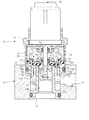
図1及び図2において10,12はそれぞれバルブボデーを構成する第1部材,第2部材で、第2部材12は更にそれぞれ円筒形状をなす上部14と、下部16と、中間部18とからなっており、それらが軸方向に組み付けられている。
ここで第2部材12、即ち上部14,下部16及び中間部18は何れも樹脂製とされている。
また下部16には円筒部22が、後述の整流部64とともに一体に構成されている。
Next, a pilot flow control valve according to an embodiment of the present invention will be described in detail with reference to the drawings.
1 and 2,
Here, the
A
20は主水路で、この主水路20上に後述のダイヤフラム弁からなる主弁26が設けられている。図中20aは主水路20における1次側の流入水路,20bは円筒部22の内側に形成された2次側の流出水路で、54はその末端の流出口を表している。
円筒部22の先端部(図中上端部)は、円環状をなす主弁座24として構成されており、また円筒部22の外周側には、1次側の流入水路20aの一部をなす流入室50が形成されている。
A front end portion (upper end portion in the figure) of the
上記ダイヤフラム弁からなる主弁26は、主水路20の開閉及び開度調節を行うもので(以下主水路20の開閉と開度調節とを含めて単に開度調節とする)、シール部材を兼ねたゴム等の弾性体からなるダイヤフラム膜28と、硬質の主弁本体30とからなっている。
この主弁26は、ダイヤフラム膜28の外周端部がバルブボデーにて固定状態に保持され、その中心部が軸心方向(図中上下方向)に進退移動(変位)して主弁座24との距離を変化させ、主水路20の開度を変化させる。
The
In the
詳しくは、主弁26は主弁座24への着座によって主水路20を遮断し、また主弁座24から図中上向きに離間することによって主水路20を開放する。
また主弁座24からの離間量に応じて開度を大小変化させ、主水路20を流れる水の流量、即ち給水流量を調節する。
Specifically, the
Further, the opening degree is changed in accordance with the distance from the
この主弁26の図中上側の背後には、背圧室32が形成されている。
背圧室32は、内部の圧力を主弁26に対して図中下向きの閉弁方向の押圧力として作用させる。
主弁26には、これを貫通して流入室50と背圧室32とを連通させる導入小孔33が設けられている。
この導入小孔33は、流入室50からの水を背圧室32に導いて背圧室32の圧力を増大させる。
A
The
The
The introduction
主弁26にはまた、これを貫通して背圧室32と流出水路20bとを連通させる水抜水路としてのパイロット水路34が設けられている。
このパイロット水路34は、背圧室32内の水を流出水路20bに抜いて背圧室32の圧力を減少させる。
The
The
図3に示しているように主弁26にはまた、その中心部においてこれを軸心方向に貫通する貫通穴36が設けられており、そこにパイロット弁35が挿通され、このパイロット弁35の外周面と貫通穴36の内周面との間に、通路幅が狭小な環状をなす上記パイロット水路34が形成されている。
この主弁26には、貫通穴36の内周面に沿って主弁26の軸心周りに環状をなすパイロット弁座37が一体に設けられている。
38はこのパイロット弁座37におけるシール部で、径方向内方が開放された形態の環状の嵌込溝72と、そこに嵌め込まれて保持された弾性を有するリング状のシール部材としてのOリング40が備えられている。
尚、嵌込溝72は主弁26、詳しくは主弁本体30の上面に起立状態に設けられた円筒形状の且つ上面が開放された堤部に対し、閉鎖部材74が下向きに嵌着されることによって形成されている。
As shown in FIG. 3, the
The
The
上記パイロット弁35は、このパイロット弁座37に対し主弁26の軸心に沿って図中上下方向に、即ち軸方向に進退移動可能に嵌合するようになっている。
詳しくはこのパイロット弁35は、断面円形をなし且つ図中上下方向即ち進退方向において外径が同径のシール部42と、その下側(図中下側)の環状の凹所44とを有している。
環状の凹所44の軸方向の各端部は、凹所44の最小径部に向かって漸次小径となるテーパ面46とされており、そのテーパ面46の大径側の各端に段付部48,49が形成されている。
The
Specifically, the
Each end portion in the axial direction of the
尚、図1はパイロット弁35の止水時の状態を表しており、このときパイロット弁35はシール部42をOリング40を介してパイロット弁座37に対し全周に亘って径方向に弾性的に接触嵌合させ、パイロット弁35とパイロット弁座37との間を水密にシールした状態にある。
またこのとき、主弁26は主弁座24に着座した状態にあって、主水路20は閉鎖された状態にある。
FIG. 1 shows the state of the
At this time, the
一方図2及び図3は最大吐水時の状態を表しており、このときパイロット弁35はシール部42がパイロット弁座37から離間した状態にあって、それらの間に微小な隙間を形成している。
またこのとき、主弁26は主弁座24から図中上向きに大きく離間した状態にあって、主水路20を大きく開いた状態にある。
On the other hand, FIG. 2 and FIG. 3 show a state at the time of maximum water discharge. At this time, the
Further, at this time, the
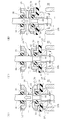
図4,図5はパイロット弁35の移動による流調(流量調節)時の作用を表している。
この実施形態では、パイロット弁35が図1の止水状態から図中上向きに後退移動すると、パイロット弁35とパイロット弁座37との間に隙間が生じ、背圧室32内の水がパイロット水路34を通じて流出水路20b側に抜け出して背圧室32の圧力が減少する。
そこで図4(I)に示しているように主弁26が流入室50との圧力差により図中上向きに後退移動し、流入室50の圧力と背圧室32の圧力とがバランスする位置で主弁26の後退移動が停止する。
この主弁26の後退移動によって、主弁26と主弁座24との間に隙間が生じ、流入室50から流出水路20bに向けて水が流出する。
4 and 5 show the action at the time of flow adjustment (flow rate adjustment) by the movement of the
In this embodiment, when the
Therefore, as shown in FIG. 4I, the
By the backward movement of the
この状態からパイロット弁35が更に図中上向きに後退移動させられると、背圧室32の圧力と流入室50との圧力をバランスさせるようにして、主弁26がパイロット弁35の後退移動に追従して後退移動し、主水路20の開度を更に広くして主水路20を流れる水の流量を増大させる(図4(II),(III)参照)。
From this state, when the
一方パイロット弁35が、図5(I)に示しているように図中下向きに前進移動すると、パイロット弁35とパイロット弁座37との間、詳しくはパイロット弁35におけるシール部42とパイロット弁座37に保持されたOリング40との間の隙間が小さくなって、即ちパイロット水路34の開度が小さくなって、背圧室32から流出水路20bに抜ける水の量が少なくなり、背圧室32の圧力が増大する。
On the other hand, when the
このため、その増大した圧力により主弁26が今度は図中下向きに前進移動して、背圧室32の圧力と流入室50との圧力をバランスさせる位置で停止する(図5(II)参照)。
このとき主弁26と主弁座24との間の隙間は小さくなって、即ち主水路20の開度が小さくなって、主水路20を流れる水の流量が減少する。
For this reason, the
At this time, the gap between the
そしてこの状態から更にパイロット弁35が図中下向きに前進移動すると主水路20の開度が更に小さくなり、流れる水の流量が更に減少する(図5(III)参照)。そして更なるパイロット弁35の前進移動によって、図1に示す止水状態となる。
When the
尚、パイロット弁35の後退移動及び前進移動によってパイロット弁35とパイロット弁座37即ちOリング40との間に生じる隙間が大きくなったり小さくなったりするのはほぼ瞬間的であり、全体としてみるとパイロット弁座37即ち主弁26は、パイロット弁35とパイロット弁座のOリング40との間の隙間を一定に保つようにして、パイロット弁35の前進及び後退移動に追従して同じ方向に進退移動する。
It is almost instantaneous that the clearance generated between the
図1において56は駆動軸で、この駆動軸56は一様な円形断面且つ一様な外径で軸方向に延びており、図中下部に上記のパイロット弁35が一体に構成されている。
この図において、58は回転式の操作部(ハンドル)で、この操作部58と駆動軸56との間に、操作部58の回転操作によりその操作量に応じて駆動軸60をねじ送りで進退させてパイロット弁35を図中上下方向に一体に進退移動させ、その位置を変化させる流調機構(図示省略)が組み込まれている。
In FIG. 1,
In this figure, 58 is a rotary operation unit (handle), and the drive shaft 60 is advanced and retracted by screw feed between the
即ちこの実施形態では、操作部58を回転操作すると回転量に応じてパイロット弁35が図中上下に進退移動して、主弁26をこれに追従して変位させる。
これによって主水路20を流れる水の流量調節が行われる。
That is, in this embodiment, when the
As a result, the flow rate of water flowing through the
尚この実施形態では、操作部58の回転操作による水量調節時に、詳しくは水量を減少させていくときに、パイロット弁35をその前進端まで前進させて止水も行うようになしている。
即ち操作部58の回転操作によって止水と吐水も行うようになしている。
In this embodiment, when adjusting the amount of water by rotating the
That is, the
但し操作部58と駆動軸56との間に、操作部58を押込むごとに一定のストロークで駆動軸56即ちその先端部のパイロット弁35を上昇位置である吐水位置から下降位置である止水位置まで若しくはその逆に移動させ、且つそれぞれの位置に位置保持する吐止水切替機構を組み込んでおいて、パイロット弁35を吐水位置と止水位置とに切り替え、且つそれぞれの位置に位置保持するようになしておくこともできる。
However, every time the
この場合には、操作部58の回転操作によってはパイロット弁35が止水位置まで前進しないようにストッパ機構を設けておくことが望ましい。但しこの場合においても操作部58の回転操作によってパイロット弁35を止水位置まで前進させるようになすこともできる。
尚、駆動軸56と背圧室32との間はOリング61にて水密にシールされている。
またバルブボデーにおける第2部材16と第1部材10との間が、Oリング62にて水密にシールされている。
In this case, it is desirable to provide a stopper mechanism so that the
The
Further, the
上記流入室50には、流入水路20aからの水の流れを主弁26の軸心方向に整えた上で主弁26に作用させる整流部64が設けられている。
この整流部64もまた樹脂製とされており、第2部材12における下部16に一体に構成されている。
The
The rectifying
この整流部64は、周方向に所定ピッチで設けられて径方向に放射状に延びる案内板66と、円筒部22と同心の環状をなす案内板68とを有しており、そしてそれらによって仕切られた内周側の多数の整流路70Aと、外周側の多数の整流路70Bとを有している。
The rectifying
上記ダイヤフラム弁から成る主弁26の主弁本体30には、円筒部22の内部に嵌入して主弁26の移動時の案内をなす主弁ガイド74が一体に構成されている。
The main valve
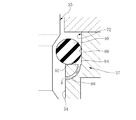
Oリング40は、図3及び図6に示しているように嵌込溝72の溝底面80に弾性接触して、嵌込溝72との間を水密にシールしている。
Oリング40はまた、嵌込溝72の溝側面82、詳しくは背圧室32にてOリング40が押圧される側の溝側面82にも弾性的に接触しており、これにより嵌込溝72の隅に角部空間、具体的には溝底面80と溝側面82及びOリング40にて囲まれた空間84が形成されている。
尚、図6において実線で示すOリング40の形状はOリング40が変形する前の形状を、また破線はOリング40が背圧室32の圧力で変形したときの形状を表している。
As shown in FIGS. 3 and 6, the O-
The O-
6, the shape of the O-
図10に示す本願の先願に係る流調弁にあっては、この角部空間が密閉の空間をなしているが、図3(B),(C)に示すようにこの実施形態では嵌込溝72の溝側面82に複数の連通溝(連通路)86が放射状に設けられており、この連通溝86によって空間84が、パイロット水路34を通じて2次側の流出水路20bに連通させられており、空間84が流出水路20bへの開放空間とされている。
In the flow control valve according to the prior application of the present application shown in FIG. 10, this corner space forms a sealed space, but in this embodiment, as shown in FIGS. A plurality of communication grooves (communication paths) 86 are provided radially on the
従ってこの実施形態では、空間84をグリスや水が充填していた場合であっても、背圧室32の圧力でOリング40が図中下向きに圧縮弾性変形したとき、その圧力によって空間84内部のグリスや水が連通溝86を通じて流出水路20b側へと抜け出、従って空間84内のグリスや水がOリング40に対して大きな抵抗力として働くことはなく、Oリング40は背圧室32の圧力によって空間84内のグリスや水を連通溝86に沿って抜け出させつつ容易に圧縮変形することができる。
Therefore, in this embodiment, even when the
従ってこの実施形態では、空間84にグリスや水が閉じ込められてしまうことによってOリング40の変形が抑制され、これにより流調特性が不安定化したり、或いは経時的に流調特性が変化してしまうといった問題を解決でき、安定した流調特性で水量調節を行うことができる。
また空間84にエアが閉じ込められるといったこともないので、空間84に閉じ込められたエアによる抵抗によってOリング40の変形が抑制され、そのことによって流調特性が不安定化してしまう問題も解決できる。
Therefore, in this embodiment, grease or water is confined in the
Further, since the air is not confined in the
また空間84にグリスや水或いはエアが閉じ込められてOリング40の変形抵抗が大きくなるということもないので、止水の際の操作抵抗が大きくなる問題も解消することができる。
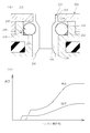
因みに図6(B)は、1次側の流入水路20aの圧力が高い高圧時と、圧力が低い低圧時とにおける流調特性を、横軸に操作部の操作量(ハンドル操作角)、縦軸に流量をとって表したもので、図に示しているようにこの実施形態によれば、操作部58を止水方向に操作したときに、高圧時において早い段階で止水が行われるといったことがなく、高圧時,低圧時何れもほぼ同じ操作位置で止水を行わせることができる。
Further, since grease, water, or air is not confined in the
6B shows the flow characteristics when the pressure of the primary
図7は本発明の他の実施形態を示している。
この実施形態は、空間84とパイロット水路34の嵌込溝72の下流部とにまたがって、パイロット弁座37の側に貫通穴88を連通路として形成した例を示している。
この図7に示す実施形態においても上記実施形態と同様の効果を奏することができる。
FIG. 7 shows another embodiment of the present invention.
This embodiment shows an example in which a through
In the embodiment shown in FIG. 7, the same effects as in the above embodiment can be obtained.
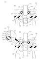
次に図8は本発明の更に他の実施形態を示している。
この実施形態は、主弁26の上面にパイロット弁座37を円環状に且つ突出状に構成する一方、パイロット弁35をパイロット弁座37に対して軸方向に移動可能に外嵌する筒状に構成して、そのパイロット弁35の側にOリング40と嵌込溝72とを備え(図8(A))、或いはパイロット弁座37の側に嵌込溝72とOリング40とを備え(図8(B))、それぞれのシール部42,38を形成した例である。
Next, FIG. 8 shows still another embodiment of the present invention.
In this embodiment, the
尚、図8(A)において38はパイロット弁座37のシール部を、また(B)において42はパイロット弁35のシール部をそれぞれ表している。
(B)の例ではパイロット弁座37のシール部38に備えられた嵌込溝72の溝側面82に連通溝86が放射状に設けられ、また(A)の例ではパイロット弁35のシール部42に備えられた嵌込溝72の溝側面82に連通溝86が放射状に設けられている。
In FIG. 8A,
In the example of (B), the
尚、図(B)の例ではOリング40に対する変形の抵抗が大きく、Oリング40の変形が小さいと、かかるOリング40とパイロット弁35との間の隙間は上記とは逆に大となり、またOリング40の変形が大きいと、Oリング40とパイロット弁35との間の隙間は小となる。
このような場合にも流調特性が不安定化するが、この実施形態においても連通溝86を設けることによって、嵌込溝72の隅の角部空間にグリースや水が閉じ込められることによってOリング40に対する変形抵抗が大きくなるといったことが防止されるため、上記実施形態及び図8(A)に示す場合と同様に安定した流調特性が得られる。
尚、図8の実施形態においても連通溝86に代えて上記の貫通孔88を設けることも可能である。
In the example of FIG. (B), when the deformation resistance of the O-
Even in such a case, the flow characteristics become unstable, but in this embodiment as well, by providing the
In the embodiment shown in FIG. 8, the above-described through
以上本発明の実施形態を詳述したがこれはあくまで一例示である。
例えば本発明においては、Oリング等のシール部材における溝側面82への接触面の側、即ち背圧室の圧力にて嵌込溝72の溝側面82に押圧される側の面に、上記の空間84と2次側の流出通路20bとを連通させるための溝その他の連通路を設けておくといったことも可能であるし、また本発明は上例以外の他の様々な径方向シール構造のパイロット式流調弁に対して適用可能である等、本発明はその趣旨を逸脱しない範囲において種々変更を加えた形態で構成可能である。
Although the embodiment of the present invention has been described in detail above, this is merely an example.
For example, in the present invention, the surface of the sealing member such as an O-ring that contacts the
20 主水路
20a 流入水路
20b 流出水路
24 主弁座
26 主弁
32 背圧室
33 導入小孔
34 パイロット水路
35 パイロット弁
37 パイロット弁座
38,42 シール部
40 Oリング
72 嵌込溝
80 溝底面
82 溝側面
84 空間
86 連通溝
88 貫通孔
20
Claims (4)
(ロ)該主弁の背後に形成され、内部の圧力を該主弁に対して閉弁方向の押圧力として作用させる背圧室と
(ハ)前記主水路における1次側の流入水路の水を該背圧室に導いて該背圧室の圧力を増大させる導入小孔と
(ニ)該背圧室と前記主水路における2次側の流出水路とを連通させる状態に前記主弁を貫通して設けられ、該背圧室の水を該流出水路に抜いて該背圧室の圧力を減少させるパイロット水路と
(ホ)前記主弁と同方向に進退移動して該主弁の側に設けられたパイロット弁座に対する相対位置を変化させ、該パイロット水路の開度を制御するパイロット弁と
を備え、該パイロット弁の進退移動に追従して前記主弁を進退移動させて前記主水路の流量調節を行うパイロット式流調弁において、
前記主弁及びパイロット弁の進退方向である軸方向に対して前記パイロット弁座を径方向の向きに環状に設けて、該パイロット弁座のシール部若しくは該パイロット弁のシール部にリング状の弾性を有するシール部材と該シール部材を嵌め込んで保持する環状の嵌込溝とを具備させ、該パイロット弁の前進端で該パイロット弁のシール部を前記シール部材を介して前記パイロット弁座に対し径方向に接触嵌合させて前記パイロット水路を閉鎖する閉弁状態とする一方、該パイロット弁の後退移動により該パイロット弁の前記シール部を前記パイロット弁座のシール部より軸方向に離間させて前記パイロット水路を開き且つ離間量に応じて該パイロット水路の開度を変化させるようになし、
前記シール部材は前記嵌込溝の溝底面に常時水密シール状態に接触させてあるとともに、
前記嵌込溝の溝底面、前記背圧室の圧力で該シール部材が押圧される側の溝側面及び該シール部材で囲まれた空間と前記2次側の流出水路とを連通状態とする連通路を設けて、該空間を該流出水路への開放空間となしたことを特徴とするパイロット式流調弁。 (A) a main valve that moves forward and backward in the direction of approaching and separating from the main valve seat to change the opening of the main waterway
(B) a back pressure chamber formed behind the main valve and acting on the main valve as a pressing force in the valve closing direction;
(C) an introduction small hole for guiding the water in the primary inflow water channel in the main water channel to the back pressure chamber to increase the pressure in the back pressure chamber;
(D) The back pressure chamber is provided through the main valve so as to communicate with the secondary outflow water channel in the main water channel, and water in the back pressure chamber is drawn into the outflow water channel to Pilot waterways to reduce chamber pressure and
(E) a pilot valve that moves forward and backward in the same direction as the main valve to change a relative position with respect to a pilot valve seat provided on the side of the main valve, and controls the opening of the pilot water channel; In a pilot-type flow control valve that adjusts the flow rate of the main water channel by moving the main valve forward and backward to follow the forward and backward movement of the valve,
The pilot valve seat is provided in an annular shape in the radial direction with respect to the axial direction which is the advancing / retreating direction of the main valve and the pilot valve, and a ring-shaped elasticity is provided on the seal portion of the pilot valve seat or the seal portion of the pilot valve A seal member having an annular fitting groove for fitting and holding the seal member, and the pilot valve seal portion at the forward end of the pilot valve with respect to the pilot valve seat via the seal member The valve is closed so that the pilot water channel is closed by contact fitting in the radial direction, while the pilot valve is moved backward to separate the seal portion of the pilot valve from the seal portion of the pilot valve seat in the axial direction. Opening the pilot water channel and changing the opening of the pilot water channel according to the separation amount,
The seal member is always in contact with the bottom surface of the fitting groove in a watertight seal state,
Groove bottom surface of the front Symbol Hamakomimizo, the seal member at a pressure of the back pressure chamber is communicated with each other and the outflow canal of the the space surrounded by the groove side surfaces and the sealing member on the side which is pressed secondary A pilot-type flow control valve, characterized in that a communication passage is provided to make the space an open space to the outflow water channel.
Priority Applications (1)
| Application Number | Priority Date | Filing Date | Title |
|---|---|---|---|
| JP2006244681A JP4850004B2 (en) | 2006-09-08 | 2006-09-08 | Pilot flow control valve |
Applications Claiming Priority (1)
| Application Number | Priority Date | Filing Date | Title |
|---|---|---|---|
| JP2006244681A JP4850004B2 (en) | 2006-09-08 | 2006-09-08 | Pilot flow control valve |
Publications (2)
| Publication Number | Publication Date |
|---|---|
| JP2008064255A JP2008064255A (en) | 2008-03-21 |
| JP4850004B2 true JP4850004B2 (en) | 2012-01-11 |
Family
ID=39287138
Family Applications (1)
| Application Number | Title | Priority Date | Filing Date |
|---|---|---|---|
| JP2006244681A Expired - Fee Related JP4850004B2 (en) | 2006-09-08 | 2006-09-08 | Pilot flow control valve |
Country Status (1)
| Country | Link |
|---|---|
| JP (1) | JP4850004B2 (en) |
Families Citing this family (3)
| Publication number | Priority date | Publication date | Assignee | Title |
|---|---|---|---|---|
| JP5648179B2 (en) * | 2011-03-30 | 2015-01-07 | 株式会社Lixil | Flow control valve device |
| JP5648180B2 (en) * | 2011-05-18 | 2015-01-07 | 株式会社Lixil | Pilot flow control valve device |
| CN107588205A (en) * | 2017-10-20 | 2018-01-16 | 广州海鸥卫浴用品股份有限公司 | Mechanical compression formula switch valve core |
Family Cites Families (7)
| Publication number | Priority date | Publication date | Assignee | Title |
|---|---|---|---|---|
| JPS5416534B2 (en) * | 1974-02-26 | 1979-06-22 | ||
| JPS62106079A (en) * | 1985-11-01 | 1987-05-16 | Suntory Ltd | Dithiocarbamoylmethylpyridine derivative and production thereof |
| JPH04302790A (en) * | 1991-03-29 | 1992-10-26 | Toto Ltd | Diaphragm type flow control valve |
| JPH10159737A (en) * | 1996-12-03 | 1998-06-16 | Marushin Kogyo Kk | Air pump |
| JP2003278939A (en) * | 2002-03-20 | 2003-10-02 | Toto Ltd | Pressure chamber type diaphragm valve |
| JP2004190625A (en) * | 2002-12-13 | 2004-07-08 | Bunsan Shu | Piston for air compressor |
| JP4818650B2 (en) * | 2005-07-12 | 2011-11-16 | 株式会社Lixil | Pilot flow control device |
-
2006
- 2006-09-08 JP JP2006244681A patent/JP4850004B2/en not_active Expired - Fee Related
Also Published As
| Publication number | Publication date |
|---|---|
| JP2008064255A (en) | 2008-03-21 |
Similar Documents
| Publication | Publication Date | Title |
|---|---|---|
| JP4915753B2 (en) | Pilot type valve device | |
| JP4787050B2 (en) | Pilot-type water stop / flow control device | |
| JP7369815B2 (en) | electronic expansion valve | |
| JP4850004B2 (en) | Pilot flow control valve | |
| JP4818650B2 (en) | Pilot flow control device | |
| KR101290283B1 (en) | Control valve | |
| JP2007024062A5 (en) | ||
| JP2009014020A (en) | Pilot flow control valve device | |
| JP4602857B2 (en) | Pilot type flow control device and main valve unit used therefor | |
| JP2009121589A (en) | Automatic temperature-adjustable hot and cold water mixing valve | |
| US11261990B2 (en) | Actuator and valve device | |
| JP5648180B2 (en) | Pilot flow control valve device | |
| JP4738078B2 (en) | Pilot flow control device | |
| JP4738077B2 (en) | Pilot flow control device | |
| JP2006258272A (en) | Faucet | |
| GB2594394A (en) | Equalizing device for safety valves | |
| US11835145B2 (en) | Electric valve | |
| US11047503B2 (en) | Actuator, valve device, and fluid supply system | |
| CN211039725U (en) | Switching valve device and faucet | |
| JP3869673B2 (en) | Liquid control valve | |
| JP4633489B2 (en) | Lightly operated faucet | |
| JP6120242B2 (en) | Channel opening / closing device | |
| CN112145715A (en) | Regulating valve | |
| JP2010007795A (en) | Water supply control valve | |
| JP4849990B2 (en) | Diaphragm flow control valve |
Legal Events
| Date | Code | Title | Description |
|---|---|---|---|
| A621 | Written request for application examination |
Free format text: JAPANESE INTERMEDIATE CODE: A621 Effective date: 20090318 |
|
| A977 | Report on retrieval |
Free format text: JAPANESE INTERMEDIATE CODE: A971007 Effective date: 20110427 |
|
| A131 | Notification of reasons for refusal |
Free format text: JAPANESE INTERMEDIATE CODE: A131 Effective date: 20110517 |
|
| A711 | Notification of change in applicant |
Free format text: JAPANESE INTERMEDIATE CODE: A712 Effective date: 20110523 |
|
| A521 | Request for written amendment filed |
Free format text: JAPANESE INTERMEDIATE CODE: A523 Effective date: 20110713 |
|
| TRDD | Decision of grant or rejection written | ||
| A01 | Written decision to grant a patent or to grant a registration (utility model) |
Free format text: JAPANESE INTERMEDIATE CODE: A01 Effective date: 20111018 |
|
| A01 | Written decision to grant a patent or to grant a registration (utility model) |
Free format text: JAPANESE INTERMEDIATE CODE: A01 |
|
| A61 | First payment of annual fees (during grant procedure) |
Free format text: JAPANESE INTERMEDIATE CODE: A61 Effective date: 20111018 |
|
| R150 | Certificate of patent or registration of utility model |
Ref document number: 4850004 Country of ref document: JP Free format text: JAPANESE INTERMEDIATE CODE: R150 Free format text: JAPANESE INTERMEDIATE CODE: R150 |
|
| FPAY | Renewal fee payment (event date is renewal date of database) |
Free format text: PAYMENT UNTIL: 20141028 Year of fee payment: 3 |
|
| S111 | Request for change of ownership or part of ownership |
Free format text: JAPANESE INTERMEDIATE CODE: R313111 |
|
| R350 | Written notification of registration of transfer |
Free format text: JAPANESE INTERMEDIATE CODE: R350 |
|
| LAPS | Cancellation because of no payment of annual fees |