JP4633489B2 - Lightly operated faucet - Google Patents
Lightly operated faucet Download PDFInfo
- Publication number
- JP4633489B2 JP4633489B2 JP2005026163A JP2005026163A JP4633489B2 JP 4633489 B2 JP4633489 B2 JP 4633489B2 JP 2005026163 A JP2005026163 A JP 2005026163A JP 2005026163 A JP2005026163 A JP 2005026163A JP 4633489 B2 JP4633489 B2 JP 4633489B2
- Authority
- JP
- Japan
- Prior art keywords
- valve
- pilot valve
- pilot
- main
- main valve
- Prior art date
- Legal status (The legal status is an assumption and is not a legal conclusion. Google has not performed a legal analysis and makes no representation as to the accuracy of the status listed.)
- Expired - Fee Related
Links
Images


Landscapes
- Domestic Plumbing Installations (AREA)
- Fluid-Driven Valves (AREA)
Description
この発明は水栓に関し、詳しくはパイロット式流調弁機構を内蔵し、小さな操作力で簡単に操作することのできる軽操作水栓に関する。 The present invention relates to a faucet, and more particularly to a light operation faucet that incorporates a pilot-type flow control valve mechanism and can be easily operated with a small operating force.
従来より水栓として各種のものが用いられているが、これら水栓は主水路の開度を変化させる主弁を弁座に対して接近離間方向に進退運動させる際に大きな力を要し、操作が重いといった問題があった。
そこで水栓における操作を軽くする手段として、かかる水栓をパイロット式流調弁機構、即ちパイロット弁を進退運動させることによって主弁をこれに追従して進退運動させ、主水路の開度を変化させる方式のパイロット式流調弁機構を内蔵した水栓とすることが考えられる。
Various types of faucets have been used in the past, but these faucets require a large force to move the main valve that changes the opening of the main waterway in the approaching and separating direction with respect to the valve seat, There was a problem that operation was heavy.
Therefore, as a means to lighten the operation of the faucet, the main valve is moved forward and backward by moving the faucet with a pilot-type flow control mechanism, i.e., moving the pilot valve back and forth, thereby changing the opening of the main water passage. It is conceivable to use a faucet with a built-in pilot flow control valve mechanism.
例えば下記特許文献1にこの種パイロット式流調弁機構の構成が開示されている。図9はその具体例を示している。
同図において200,202は主水路を形成する1次側の流入水路,2次側の流出水路で、204はその主水路上に設けられたダイヤフラム弁から成る主弁である。
この主弁204は、主弁座206に対し接近離間方向に進退運動して主水路の開度を変化させ、その開度に応じて主水路における流量を調節する。
For example, the following Patent Document 1 discloses the configuration of this kind of pilot type flow regulating mechanism. FIG. 9 shows a specific example.
In the figure,
The
208は主弁204の背後に形成された背圧室で、この背圧室208は、主弁204に対して内部の圧力を閉弁方向の押圧力として作用させる。
主弁204には、これを貫通して流入水路200と背圧室208とを連通させる、小孔から成る導水孔210が設けられている。
この導水孔210は、流入水路200からの水を背圧室208に導いて背圧室208の圧力を増大させる。
主弁204にはまた、これを貫通して背圧室208と流出水路202とを連通させる水抜水路としてのパイロット水路212が設けられている。
このパイロット水路212は、背圧室208内の水を流出水路202に抜いて背圧室208の圧力を減少させる。
The
The
The
The
214は駆動軸(駆動部材)216に一体運動状態に設けられたパイロット弁で、このパイロット弁214が主弁204に設けられたパイロット弁座218に対し図中上下方向、即ち主弁204の進退方向と同じ方向に進退運動することでパイロット水路212の開度(背圧室208に対する開度)が変化せしめられる。
図9において220はパイロット弁214を駆動軸216とともに進退駆動させる電気的駆動装置である。
A
In FIG. 9,
この図9に示すパイロット式流調弁機構にあっては、パイロット弁214がパイロット弁座218に向かって前進運動すると、パイロット弁214とパイロット弁座218との隙間が小さくなってパイロット水路212の開度が小となり、背圧室208からパイロット水路212を通じて流出水路202に抜ける水の量が少なくなって背圧室208の圧力は増大する。
また一方パイロット弁214が図中上向きに後退運動すると、パイロット弁214とパイロット弁座218との隙間が大きくなってパイロット水路212の開度が大となり、ここにおいて背圧室208からパイロット水路212を通じて流出水路202に抜ける水の量が多くなって背圧室208の圧力が減少する。
そして主弁204は、その背圧室208の圧力と流入水路200の圧力とをバランスさせるようにして、パイロット弁214の進退運動に追従して図中上下方向に進退運動し、主水路の開度を変化させる。
そしてその主水路の開度の変化に応じて、流入水路200から流出水路202への水の流量が調節される。
In the pilot type flow regulating mechanism shown in FIG. 9, when the
On the other hand, when the
Then, the
The flow rate of water from the
この図9に示すパイロット式流調弁機構にあっては、背圧室208の圧力の増減に基づいて主弁204を進退運動させ、そしてその背圧室208の圧力の増減をパイロット弁214の進退運動により制御するようになしていることから、小さい力で主弁204を開閉弁動作させることができ、軽い操作で流量調節を行うことができる特長を有する。
In the pilot type flow regulating mechanism shown in FIG. 9, the
しかしながらこのパイロット式流調弁機構の場合、導水孔210が主弁204の中心から偏って位置していることや、流入水路200を通じて流れて来た水の勢いが主弁204に対して必ずしも全面に亘り均等に働かないことなどの種々の理由によって、主弁204が主弁座206に対して必ずしも垂直姿勢を維持した状態で図中上下方向に進退運動せず、場合によって主弁204が傾いてしまうことがある。
However, in the case of this pilot-type flow control mechanism, the
このパイロット式流調弁機構においては、主弁204、詳しくはパイロット弁座218とパイロット弁214との間に所定の隙間を生ぜしめつつ、パイロット弁214の図中下降運動によって即ち前進方向の運動によって主弁204が追従して前進運動し、その際のパイロット弁214と主弁204との間の隙間は例えば0.02〜0.05mm程度の極めて微小な隙間であるため、主弁204が傾いてしまうとパイロット弁214が主弁204に片当りしてしまって、操作が重くなるといった問題が生ずる。
パイロット弁214が主弁204に対して、具体的にはパイロット弁座218に対して片当りしてしまうと、パイロット弁214が図中下向きに前進運動しても、パイロット弁214と主弁204との隙間がそれ以上に小さくならず、その結果として背圧室208の圧力がパイロット弁214の下降運動に伴って増大せず、そのためパイロット弁214、詳しくは駆動軸216が直接主弁204を下向きに押すこととなって操作荷重が大となり、操作が重くなってしまうのである。
In this pilot-type flow control mechanism, a predetermined clearance is created between the
If the
従って例えばステッピングモータ等小型のアクチュエータを用いて駆動軸216を駆動するようになした場合、駆動力不足によって閉弁動作の途中でパイロット弁214,主弁204が停止してしまうといった不具合が生じ得る。
この問題は主弁204がダイヤフラム弁から成っている場合に、かかるダイヤフラム弁が特に傾き易いことから上記の問題を生じ易いが、主弁がピストン弁から成るものである場合においても傾きを生じる場合があり、この場合には上記と同様な問題が生じる。
Therefore, for example, when the
This problem is likely to occur when the
本発明は以上のような事情を背景とし、パイロット式流調弁機構を内蔵した軽操作水栓において、主弁の傾きによって操作が重くなる問題を解決し、常に軽く操作を行うことのできる軽操作水栓を提供することを目的としてなされたものである。 In the light operation faucet incorporating the pilot type flow control mechanism, the present invention solves the problem that the operation becomes heavy due to the inclination of the main valve, and the light operation that can always be performed lightly. The purpose is to provide an operation faucet.
而して請求項1のものは、(イ)主弁座に対して接近離間方向に進退運動して主水路の開度を変化させる主弁と、(ロ)内部の圧力を該主弁に対して閉弁方向の押圧力として作用させる背圧室と、(ハ)前記主水路における1次側の流入水路の水を前記背圧室に導いて該背圧室の圧力を増大させる導水孔と、(ニ)該背圧室と前記主水路における2次側の流出水路とを連通させる状態に前記主弁を貫通して設けられ、該背圧室の水を該流出水路に抜いて該背圧室の圧力を減少させるパイロット水路と、(ホ)前記主弁に設けられたパイロット弁座に対して接近離間方向に進退運動して前記パイロット水路の開度を変化させるパイロット弁と、を備え、該パイロット弁の進退運動に追従して前記主弁を進退運動させて前記主水路における流量調節を行うパイロット式流調弁機構を内蔵した軽操作水栓において、前記パイロット弁を、該パイロット弁を駆動する駆動部材から切り離して前記主弁の側に設けるとともに、該主弁には該パイロット弁の前記進退運動を案内するパイロット弁ガイドを設け、該パイロット弁を該主弁に対し該パイロット弁ガイドによる案内の下に進退運動可能に該主弁により保持させ、且つ前記駆動部材と前記パイロット弁とは、該駆動部材を該パイロット弁に対して垂直に当接させた状態で、該駆動部材の該パイロット弁と対向する面の一部が該パイロット弁に対して部分的に当接し、当接部分の周りにおいて該対向する面と該パイロット弁との間に、該パイロット弁と駆動部材との相対的な傾きを許容する隙間を生じるものとなしたことを特徴とする。 Thus, according to the first aspect of the present invention, (a) a main valve that moves forward and backward in the approaching and separating direction with respect to the main valve seat to change the opening of the main water channel, and (b) internal pressure is applied to the main valve. A back pressure chamber that acts as a pressing force in the valve closing direction; and (c) a water introduction hole that guides water in the primary inflow water channel in the main water channel to the back pressure chamber and increases the pressure in the back pressure chamber. (D) provided through the main valve in a state where the back pressure chamber communicates with the secondary outflow water channel in the main water channel, and draws water from the back pressure chamber into the outflow water channel. A pilot water passage that reduces the pressure in the back pressure chamber, and (e) a pilot valve that moves back and forth in the approaching and separating direction with respect to the pilot valve seat provided in the main valve to change the opening of the pilot water passage. A pyrometer that adjusts the flow rate in the main channel by moving the main valve forward and backward following the forward and backward movement of the pilot valve. In a lightly operated water faucet with a built-in flow control valve mechanism, the pilot valve is separated from a drive member that drives the pilot valve and is provided on the main valve side. A pilot valve guide for guiding the advancing and retreating movement, the pilot valve being held by the main valve so as to be capable of advancing and retreating under the guidance of the pilot valve guide with respect to the main valve ; and the driving member, the pilot valve, In a state in which the drive member is vertically contacted with the pilot valve, a part of the surface of the drive member facing the pilot valve is partially contacted with the pilot valve. A gap that allows a relative inclination between the pilot valve and the drive member is formed between the opposing surface and the pilot valve around the portion .
請求項2のものは、請求項1において、前記パイロット弁を後退方向に付勢する付勢手段を設け、該パイロット弁を該付勢手段による後退方向の付勢と前記駆動部材による前進方向の駆動とによって進退運動させるようになしたことを特徴とする。 According to a second aspect of the present invention, the urging means for urging the pilot valve in the backward direction is provided in the first aspect, and the pilot valve is urged in the backward direction by the urging means and in the forward direction by the driving member. It is characterized in that it can be moved forward and backward by driving.
請求項3のものは、請求項1,2の何れかにおいて、前記主弁がダイヤフラム弁であることを特徴とする。 According to a third aspect of the present invention, in any one of the first and second aspects, the main valve is a diaphragm valve .
以上のように本発明は、パイロット弁を駆動する駆動部材からパイロット弁を切り離して主弁の側に設けるとともに、その主弁にはパイロット弁の進退運動を案内するパイロット弁ガイドを設け、その主弁によりパイロット弁を主弁に対し進退運動可能に保持させるようになしたものである。 As described above, according to the present invention, the pilot valve is separated from the driving member for driving the pilot valve and provided on the main valve side, and the main valve is provided with the pilot valve guide for guiding the forward / backward movement of the pilot valve. The pilot valve is held by the valve so as to be movable back and forth with respect to the main valve.
かかる本発明によれば、主弁が主弁座に対し正しく垂直姿勢に保たれないで傾くことがあっても、主弁に保持されているパイロット弁が主弁とともに傾いた状態となり、しかもこのパイロット弁は主弁に設けたパイロット弁ガイドによる案内の下に進退運動するため、主弁の傾きにも拘わらず駆動部材による駆動によってかかるパイロット弁がパイロット弁座に対し正しく垂直姿勢を維持しつつパイロット弁座に対し接近運動(前進運動)することができる。 According to the present invention, even if the main valve is tilted without being maintained in the correct vertical position with respect to the main valve seat, the pilot valve held by the main valve is tilted together with the main valve, and this Since the pilot valve moves forward and backward under the guidance of the pilot valve guide provided on the main valve, the pilot valve that is driven by the drive member maintains the correct vertical posture with respect to the pilot valve seat despite the inclination of the main valve. An approaching motion (forward motion) can be made with respect to the pilot valve seat.
即ち、パイロット弁が主弁に設けたパイロット弁座に対し片当りして、パイロット弁の更なる前進運動にも拘わらずパイロット弁座とパイロット弁との間の隙間が小さくならないといった問題を回避でき、パイロット弁とパイロット弁座との間の隙間を全周に亘り均等に保持しつつ、パイロット弁をパイロット弁座、即ち主弁に対して前進運動させることが可能となって、パイロット弁の主弁に対する片当りによって操作が重くなるといった問題を解決することができる。 In other words, it is possible to avoid the problem that the pilot valve hits one side against the pilot valve seat provided on the main valve and the clearance between the pilot valve seat and the pilot valve does not become small despite the further forward movement of the pilot valve. The pilot valve can be moved forward with respect to the pilot valve seat, i.e., the main valve, while the gap between the pilot valve and the pilot valve seat is uniformly maintained over the entire circumference. It is possible to solve the problem that the operation becomes heavier due to a single contact with the valve.
本発明においては、パイロット弁を後退方向に付勢する付勢手段を設け、その付勢手段による後退方向の付勢と、駆動部材による前進方向の駆動とによってパイロット弁を進退運動させるようになすことができる(請求項2)。
このようにすることで、パイロット弁を円滑に開閉動作即ちパイロット弁座に対し進退運動させることができる。
ここでその付勢手段は主弁に設けておくことができる。
また付勢手段による付勢力は、駆動部材にて直接主弁を押すときに要する力よりも弱い付勢力となしておくのが良い。
In the present invention, biasing means for biasing the pilot valve in the backward direction is provided, and the pilot valve is moved forward and backward by biasing in the backward direction by the biasing means and driving in the forward direction by the drive member. (Claim 2).
By doing so, the pilot valve can be smoothly opened and closed, that is, moved forward and backward with respect to the pilot valve seat.
Here, the biasing means can be provided in the main valve.
Further, it is preferable that the urging force by the urging means is a urging force that is weaker than the force required when the main valve is directly pressed by the drive member.
本発明においてはまた、上記主弁をダイヤフラム弁にて構成しておくことができる(請求項3)。 In the present invention, the main valve can be constituted by a diaphragm valve.
尚上記とは他の解決手段として、主弁及び駆動部材の一方に主弁の進退方向に延びるガイド孔を設けるとともに、他方にそのガイド孔内に挿入されるガイド突部を設けて、それらガイド孔とガイド突部とで主弁を進退方向に運動案内する主弁ガイドを構成しておくことができ、このようにすれば主弁自体の傾きを有効に防止することができ、従ってその主弁の傾きによる操作抵抗の増大を防止して、主弁に対する軽操作を常時確保することが可能となる。 As another solution to the above, a guide hole extending in the main valve's forward / backward direction is provided on one of the main valve and the drive member, and a guide protrusion inserted into the guide hole is provided on the other side. The main valve guide for moving the main valve in the forward / backward direction can be configured by the hole and the guide protrusion, and in this way, the inclination of the main valve itself can be effectively prevented, and therefore the main valve guide can be effectively prevented. It is possible to prevent an increase in operation resistance due to the inclination of the valve and always ensure a light operation on the main valve.
次に本発明の実施形態を図面に基づいて詳しく説明する。
図1において、10は本実施形態の軽操作水栓で、12,14は主水路を形成する1次側の流入水路,2次側の流出水路で、16はその主水路上に設けられたダイヤフラム弁から成る主弁である。
主弁16は主弁本体18と、これにより保持されたゴム製のダイヤフラム膜20とから成っている。
Next, embodiments of the present invention will be described in detail with reference to the drawings.
In FIG. 1, 10 is a lightly operated water faucet according to the present embodiment, 12 and 14 are a primary inflow water channel and a secondary outflow water channel forming a main water channel, and 16 is provided on the main water channel. The main valve consists of a diaphragm valve.
The
この主弁16は、主弁座22に対して接近離間方向に進退運動して主水路の開度を変化させる。
詳しくは、主弁座22への主弁16の着座によって主水路を遮断し、また主弁座22から図中上向きに離間することによって主水路を開放する。
また主弁座22からの離間量に応じて主水路の開度を大小変化させ、主水路を流れる水の流量を調節する。
The
Specifically, the main water passage is blocked by the
Further, the opening degree of the main water channel is changed in accordance with the distance from the
この主弁16の図中上側、即ち主弁16に対し流出水路14と反対側に背圧室24が形成されている。
背圧室24は、内部の圧力を主弁16に対し閉弁方向の押圧力として作用させる。
主弁16には、これを貫通して流入水路12と背圧室24とを連通させる、小孔から成る導水孔26が設けられている。
この導水孔26は、流入水路12からの水を背圧室24に導いて背圧室24の圧力を増大させる。
主弁16にはまた、これを貫通して背圧室24と流出水路14とを連通させる水抜水路としてのパイロット水路28が設けられている。
このパイロット水路28は、背圧室24内の水を流出水路14に抜いて背圧室24の圧力を減少させる。
A
The
The
The
The
The
32はパイロット式流調弁機構におけるパイロット弁で、この実施形態ではパイロット弁32は後述の駆動軸(スピンドル軸)(駆動部材)40と切り離されて主弁16の側に設けられ、かかる主弁16にて進退運動可能に保持されている。
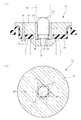
ここでパイロット弁32は略円柱状をなしていて(図3参照)図中上下方向、即ち主弁16に設けられたパイロット弁座42に対し図中上下方向(軸方向)に進退運動してパイロット水路28の開度を変化させる。
詳しくは、パイロット弁32がパイロット弁座42に着座(図2(A)参照)することでパイロット水路28が遮断され、またパイロット弁32がパイロット弁座42から図中上向きに軸方向に離間することでパイロット水路28が開放される。
更にパイロット弁32のパイロット弁座42からの離間量に応じてパイロット水路28の開度が変化せしめられる。
Here, the
Specifically, when the
Further, the opening degree of the
図2(A)に明らかに示しているように、主弁16にはガイド孔(パイロット弁ガイド)30が設けられており、そのガイド孔30内にパイロット弁32が進退運動可能に保持されている。
ここでガイド孔30は、パイロット弁32を保持する保持孔としての働きと、パイロット弁32を図中上下方向(軸方向)に進退運動案内するガイド孔としての働きを有している。
As clearly shown in FIG. 2A, the
Here, the
具体的には、このガイド孔30の内周面には図2(B),図3に示しているように周方向に沿って一定間隔で軸方向に延びるリブ34が内向きに突出形成されており、それらリブ34によってパイロット弁32が軸方向に摺動可能(進退運動可能)に保持されている。
これらリブ34と34との間には水路36が確保されており、この水路36を通じて背圧室24とパイロット水路28とが連通するようになっている。
尚このパイロット弁32の図2(A)中下面にはゴム等の弾性材から成るパッキン46が設けられており、具体的にはこのパッキン46がパイロット弁座42に対して着座する。
Specifically, as shown in FIGS. 2B and 3,
A
A packing 46 made of an elastic material such as rubber is provided on the lower surface of the
図2(A)に示しているように、このパイロット弁32と主弁16における主弁本体18との間にはコイルスプリングから成る復帰ばね(付勢手段)48(図3参照)が介装されており、パイロット弁32は、常時この復帰ばね48によって図中上向き即ち後退方向に付勢されている。
またパイロット弁32の上面は上向きの凸曲面38とされている。
尚この復帰ばね48の付勢力は弱いものとされている。詳しくは駆動軸40にて主弁16を直接押す際の力よりも復帰ばね48の付勢力が弱くされている。
As shown in FIG. 2A, a return spring (biasing means) 48 (see FIG. 3) made of a coil spring is interposed between the
The upper surface of the
The urging force of the
このパイロット式流調弁機構においては、図1に示す状態即ちパイロット弁32がパイロット弁座42に着座し、また主弁16が主弁座22に着座した状態で主水路が遮断され、水の流通が停止する。
In this pilot type flow regulating mechanism, the main water channel is shut off in the state shown in FIG. 1, that is, in a state where the
この状態から、図4(I)に示しているようにパイロット弁32がパイロット弁座42から図中上向きに離間してパイロット弁座42との間に隙間が生じると、その隙間を通じて背圧室24内の水がパイロット水路28を通じて流出水路14側に抜き出され、背圧室24の圧力が減少する。
すると流入水路12の圧力が背圧室24の圧力に打ち勝って、主弁16が図4(II)に示しているように図中上向きに上昇、即ち後退運動させられ、そして背圧室24の圧力と流入水路12の圧力とが丁度バランスした位置で主弁16が停止する。
このとき主弁16と主弁座22との間には隙間が生じて、その隙間を通じて流入水路12から流出水路14へと水が流れ込む。
In this state, when the
Then, the pressure of the
At this time, a gap is formed between the
この状態から更にパイロット弁32が図4(III)に示しているように図中上向きに後退運動すると、背圧室24の圧力と流入水路12との圧力をバランスさせるようにして主弁16がパイロット弁32の後退運動に追従して図中上向きに後退運動し、主水路における開度を更に大として水の流量を増大させる。
When the
一方上向きに後退運動したパイロット弁32が、図5(I)に示しているように図中下向きに前進運動し、パイロット弁32とパイロット弁座42との間の隙間が小さくなると、ここにおいて背圧室24の圧力が増大して流入水路12の圧力に打ち勝つに到り、これにより主弁16がそれらの圧力をバランスさせるように図5(II)に示しているように図中下向きに前進運動し、主弁座22との間の隙間を小さくする。即ち流入水路12から流出水路14への水の流量を減少させる。
On the other hand, as shown in FIG. 5I, the
この状態から更にパイロット弁32が図5(III)に示しているように図中下向きに前進運動すると、これに追従して主弁16が図中下向きに前進運動し、水の流量を更に減少させる。
そしてパイロット弁32が主弁16に形成されたパイロット弁座42に着座し、また主弁16が主弁座22に着座することで、流入水路12と流出水路14とが遮断された状態となって、ここに流入水路12から流出水路14への水の流れが停止する(図1に示す状態)。
When the
The
図4及び図5に示しているように、この実施形態においてはパイロット弁32と主弁16との間、詳しくはパイロット弁座42との間に完全閉弁状態(図1に示す状態)を除いて常時それらの間に隙間を生ぜしめる。そしてその隙間を大きく又は小さく変化させることで主弁16が進退運動し、主水路の水の流量を調節する。
As shown in FIGS. 4 and 5, in this embodiment, a completely closed state (the state shown in FIG. 1) is established between the
図1において、50はハンドルでこのハンドル50に対し、上記の駆動軸40がその上端部に形成された雄ねじ52と、ハンドル50に形成された雌ねじ54とによってねじ結合され、駆動軸40がハンドル50と一体に回転するようになっている。
ここで駆動軸40には外周面に環状溝が形成されていて、そこにシールリングとしての弾性を有するOリング56が装着されている。
In FIG. 1,
Here, an annular groove is formed on the outer peripheral surface of the
この駆動軸40は軸方向中間部に大径部58を有しており、その外周面に雄ねじ60が設けられている。
そしてこの雄ねじ60が、軽操作水栓10のボデー62の円筒部64の内周面に形成された雌ねじ66に螺合されている。
駆動軸40は、ハンドル50の回転により自身が一体に回転することで、雄ねじ60と雌ねじ66とによるねじ送りで図中上下の軸方向、即ち主弁16,パイロット弁32の進退方向に前進及び後退運動する。
尚この駆動軸40の下端面(パイロット弁32と対向する面)は軸直角方向の平坦面とされており、その平坦面において上記のパイロット弁32、即ちその上端面の凸曲面38に当接してパイロット弁32に対し図中下向きに駆動力を及ぼす。
The
The
The
The lower end surface of the drive shaft 40 (the surface facing the pilot valve 32) is a flat surface perpendicular to the axis, and the flat surface is in contact with the
図6は本実施形態の軽操作水栓10の作用を表している。
図1,図4に示しているようにこの実施形態ではハンドル50を正方向に回転操作すると、これと一体に駆動軸40が回転し、そしてその回転により駆動軸40が図中下向きに前進運動して、平坦な下端面でパイロット弁32を復帰ばね48の付勢力に抗して図中下向きに押し、パイロット弁32をパイロット弁座42に対して接近させる。
パイロット弁座42に接近したパイロット弁32は、パイロット弁座42との間の隙間を小さくしてパイロット水路28の開度を小さく変化させる。
そしてこれにより主弁16を追従して図中下向きに前進運動させ、主水路の開度を小さくして主水路の水の流量を少なくする。
FIG. 6 shows the operation of the
As shown in FIGS. 1 and 4, in this embodiment, when the
The
As a result, the
また一方図1,図5に示しているようにハンドル50を逆方向に回転させて駆動軸40を図中上向きに後退運動させると、パイロット弁32が復帰ばね48の付勢力にて図中上向きに後退運動し、パイロット弁座42との間の隙間を大きくしてパイロット水路28の開度を大きくする。
これに伴って主弁16がパイロット弁32の後退運動に追従して図中上向きに後退運動し、主水路の開度を大きくして主水路の水の流量を多くする。
On the other hand, as shown in FIGS. 1 and 5, when the
Along with this, the
図6に示しているようにこの実施形態では、パイロット弁32が駆動軸40から切り離されて主弁16により且つ主弁16のガイド孔30による案内の下に進退運動可能に保持されていることから、主弁16の傾きの如何に拘らずパイロット弁32が主弁16に対し、具体的にはパイロット弁座42に対し正しく垂直姿勢を維持しながらこれに接近離間運動する。即ち主弁16及びパイロット弁32の軸方向に進退運動する。
従ってこの実施形態では、主弁16が閉弁時に傾いていてもパイロット弁32が主弁16に対して、詳しくはパイロット弁座42に対して接触し片当りするといったことがなく、パイロット弁32とパイロット弁座42との間の隙間を全周に亘り均等に保持しながら、パイロット弁32が進退運動してパイロット弁座42との間の隙間を大きく又は小さく変化させる。
従ってパイロット弁32がパイロット弁座42に当ることによって、その時点から操作が重くなってしまうといった不都合を生じない。
In this embodiment, as shown in FIG. 6, the
Therefore, in this embodiment, even if the
Therefore, when the
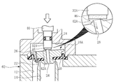
因みに図8はパイロット弁32Aを駆動軸40に固定状態に設けた場合を比較例として示したもので、この図8に示すものでは主弁16Aが傾いていると、パイロット弁32Aが図8の部分拡大図に示しているようにパイロット弁座42Aに対して片当り状態に直接接触してしまう。
従ってこの状態でパイロット弁32Aを図中下向きに前進運動させても、パイロット弁32Aとパイロット弁座42Aとの間の隙間は小さくならないで、そのままパイロット弁32Aの図中下向きの前進運動につれて主弁16Aが下向きに押されてしまう。その結果として操作荷重が大となって操作が重くなってしまう。
しかるに図6の作用図から明らかなように、本実施形態ではこうした不都合を生じない。
Incidentally, FIG. 8 shows a case where the
Accordingly, even if the
However, as apparent from the operation diagram of FIG. 6, this embodiment does not cause such inconvenience.
以上のような本実施形態の軽操作水栓10によれば、主弁16が主弁座22に対し正しく垂直姿勢に保たれないで傾くことがあっても、主弁16に保持されているパイロット弁32が主弁16とともに傾いた状態となり、しかもこのパイロット弁32は主弁16に設けたガイド孔30による案内の下に進退運動するため、主弁16の傾きにも拘わらず駆動軸40による駆動によってかかるパイロット弁32がパイロット弁座42に対し正しく垂直姿勢を維持しつつ、パイロット弁座42に対し接近運動(前進運動)することができる。
それ故パイロット弁32が主弁16に設けたパイロット弁座42に片当りし、パイロット弁32の更なる前進運動にも拘わらずパイロット弁座42とパイロット弁32との間の隙間が小さくならないといった問題を回避でき、パイロット弁32とパイロット弁座42との間の隙間を全周に亘り均等に保持しつつ、パイロット弁32がパイロット弁座42、即ち主弁16に対して前進運動することが可能となって、かかるパイロット弁32の主弁16に対する片当りによって操作が重くなるといった問題を解決することができる。
According to the
Therefore, the
本実施形態においては、パイロット弁32を後退方向に付勢する復帰ばね48を設け、その復帰ばね48による後退方向の付勢と、駆動軸40による前進方向の駆動とによってパイロット弁32を進退運動させているため、パイロット弁32を円滑に開閉動作、即ちパイロット弁座42に対して進退運動させることができる。
In the present embodiment, a
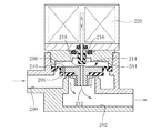
次に図7は参考例を示している。
この実施形態は、駆動軸40にパイロット弁32を一体運動状態に設けるとともに、駆動軸40に細径の下向きのピン状のガイド突部68を設け、これをパイロット水路28をガイド孔としてそこに軸方向に摺動可能、即ち主弁16の進退方向に摺動可能に挿入し、それらガイド突部68とパイロット水路28即ちガイド孔とによって、主弁16を進退方向に運動案内する主弁ガイドを構成した例である。
尚このパイロット水路28とは別にガイド孔を設けてそこにガイド突部を摺動可能に挿入し、それらによって主弁ガイドを構成するといったことも可能である。
Next, FIG. 7 shows a reference example .
In this embodiment, the
In addition, it is also possible to provide a guide hole separately from the
この図7に示す例の場合、ガイド突部68とパイロット水路28即ちガイド孔とで構成される主弁ガイドによって、主弁16の傾きを良好に防止することができる。
従って主弁16が傾くことによって、パイロット弁32が主弁16詳しくは主弁16に設けたパイロット弁座42に対し片当り状態となって操作荷重が大となり、操作が重くなるといった問題を解決することができ、主弁16に対する軽操作を常時確保することができる。
尚この実施形態において、パイロット水路28の内周面に図2(B)に示すものと同様に周方向に沿って複数のリブを設けておいて、そのリブによってガイド突部68の案内をなすようになし、そしてそのリブとリブとの間に水路を形成しておくようになすこともできる。
In the case of the example shown in FIG. 7, the main valve guide composed of the
Therefore, when the
In this embodiment, a plurality of ribs are provided along the circumferential direction on the inner peripheral surface of the
以上本発明の実施形態を詳述したがこれらはあくまで一例示であり、本発明はその趣旨を逸脱しない範囲において種々変更を加えた形態で構成可能である。 Although the embodiments of the present invention have been described in detail above, these are merely examples, and the present invention can be configured in various modifications without departing from the spirit of the present invention.
10 軽操作水栓
12 流入水路
14 流出水路
16 主弁
22 主弁座
24 背圧室
26 導水孔
28 パイロット水路
30 ガイド孔(パイロット弁ガイド)
32 パイロット弁
40 駆動軸(駆動部材)
42 パイロット弁座
48 復帰ばね
68 ガイド突部
DESCRIPTION OF
32
42
Claims (3)
(ロ)内部の圧力を該主弁に対して閉弁方向の押圧力として作用させる背圧室と
(ハ)前記主水路における1次側の流入水路の水を前記背圧室に導いて該背圧室の圧力を増大させる導水孔と
(ニ)該背圧室と前記主水路における2次側の流出水路とを連通させる状態に前記主弁を貫通して設けられ、該背圧室の水を該流出水路に抜いて該背圧室の圧力を減少させるパイロット水路と
(ホ)前記主弁に設けられたパイロット弁座に対して接近離間方向に進退運動して前記パイロット水路の開度を変化させるパイロット弁と
を備え、該パイロット弁の進退運動に追従して前記主弁を進退運動させて前記主水路における流量調節を行うパイロット式流調弁機構を内蔵した軽操作水栓において、
前記パイロット弁を、該パイロット弁を駆動する駆動部材から切り離して前記主弁の側に設けるとともに、該主弁には該パイロット弁の前記進退運動を案内するパイロット弁ガイドを設け、該パイロット弁を該主弁に対し該パイロット弁ガイドによる案内の下に進退運動可能に該主弁により保持させ、
且つ前記駆動部材と前記パイロット弁とは、該駆動部材を該パイロット弁に対して垂直に当接させた状態で、該駆動部材の該パイロット弁と対向する面の一部が該パイロット弁に対して部分的に当接し、当接部分の周りにおいて該対向する面と該パイロット弁との間に、該パイロット弁と駆動部材との相対的な傾きを許容する隙間を生じるものとなしたことを特徴とする軽操作水栓。 (A) a main valve that moves forward and backward in the approaching and separating direction with respect to the main valve seat to change the opening of the main water channel;
(B) a back pressure chamber that causes the internal pressure to act on the main valve as a pressing force in the valve closing direction;
(C) a water introduction hole for guiding the water in the primary inflow water channel in the main water channel to the back pressure chamber to increase the pressure in the back pressure chamber;
(D) The back pressure chamber is provided through the main valve so as to communicate with the secondary outflow water channel in the main water channel, and water in the back pressure chamber is drawn into the outflow water channel to Pilot waterways to reduce chamber pressure and
(E) a pilot valve that moves forward and backward in an approaching and separating direction with respect to a pilot valve seat provided on the main valve to change the opening of the pilot water channel, and follows the forward and backward movement of the pilot valve In a light operation faucet with a built-in pilot-type flow control mechanism that adjusts the flow rate in the main channel by moving the main valve forward and backward,
The pilot valve is separated from a drive member that drives the pilot valve and is provided on the main valve side. The main valve is provided with a pilot valve guide that guides the forward and backward movement of the pilot valve. The main valve is held by the main valve so as to be movable back and forth under the guidance of the pilot valve guide .
The drive member and the pilot valve are configured such that a part of a surface of the drive member facing the pilot valve is in contact with the pilot valve in a state where the drive member is brought into contact with the pilot valve vertically. A gap that allows a relative inclination between the pilot valve and the drive member between the opposing surface and the pilot valve around the contact portion. Light-operated faucet that features.
Priority Applications (1)
| Application Number | Priority Date | Filing Date | Title |
|---|---|---|---|
| JP2005026163A JP4633489B2 (en) | 2005-02-02 | 2005-02-02 | Lightly operated faucet |
Applications Claiming Priority (1)
| Application Number | Priority Date | Filing Date | Title |
|---|---|---|---|
| JP2005026163A JP4633489B2 (en) | 2005-02-02 | 2005-02-02 | Lightly operated faucet |
Publications (2)
| Publication Number | Publication Date |
|---|---|
| JP2006214480A JP2006214480A (en) | 2006-08-17 |
| JP4633489B2 true JP4633489B2 (en) | 2011-02-16 |
Family
ID=36977883
Family Applications (1)
| Application Number | Title | Priority Date | Filing Date |
|---|---|---|---|
| JP2005026163A Expired - Fee Related JP4633489B2 (en) | 2005-02-02 | 2005-02-02 | Lightly operated faucet |
Country Status (1)
| Country | Link |
|---|---|
| JP (1) | JP4633489B2 (en) |
Families Citing this family (2)
| Publication number | Priority date | Publication date | Assignee | Title |
|---|---|---|---|---|
| JP4738077B2 (en) * | 2005-07-12 | 2011-08-03 | 株式会社Inax | Pilot flow control device |
| JP5132589B2 (en) * | 2009-01-20 | 2013-01-30 | 株式会社Lixil | Pilot flow control valve |
Citations (2)
| Publication number | Priority date | Publication date | Assignee | Title |
|---|---|---|---|---|
| JPH0449280U (en) * | 1990-08-31 | 1992-04-27 | ||
| JP2001098596A (en) * | 1999-09-29 | 2001-04-10 | Inax Corp | Water discharge device |
Family Cites Families (4)
| Publication number | Priority date | Publication date | Assignee | Title |
|---|---|---|---|---|
| JPS55104175U (en) * | 1979-01-16 | 1980-07-21 | ||
| JPS61191576U (en) * | 1985-05-22 | 1986-11-28 | ||
| JPH04302790A (en) * | 1991-03-29 | 1992-10-26 | Toto Ltd | Diaphragm type flow control valve |
| JPH06346981A (en) * | 1993-06-04 | 1994-12-20 | Tgk Co Ltd | Pilot type solenoid valve |
-
2005
- 2005-02-02 JP JP2005026163A patent/JP4633489B2/en not_active Expired - Fee Related
Patent Citations (2)
| Publication number | Priority date | Publication date | Assignee | Title |
|---|---|---|---|---|
| JPH0449280U (en) * | 1990-08-31 | 1992-04-27 | ||
| JP2001098596A (en) * | 1999-09-29 | 2001-04-10 | Inax Corp | Water discharge device |
Also Published As
| Publication number | Publication date |
|---|---|
| JP2006214480A (en) | 2006-08-17 |
Similar Documents
| Publication | Publication Date | Title |
|---|---|---|
| JP4787050B2 (en) | Pilot-type water stop / flow control device | |
| JP4915753B2 (en) | Pilot type valve device | |
| JP6153684B1 (en) | Solenoid valve with durability against oxygen, hydrogen and water | |
| JP4818650B2 (en) | Pilot flow control device | |
| JP4695019B2 (en) | Water faucet | |
| JP2017201199A (en) | Flow regulating valve | |
| JP2007024062A5 (en) | ||
| JP4602857B2 (en) | Pilot type flow control device and main valve unit used therefor | |
| JP4633489B2 (en) | Lightly operated faucet | |
| WO2014171120A1 (en) | Lock device, and valve device | |
| JP4850003B2 (en) | Pilot flow control valve | |
| JP2007032271A (en) | Faucet | |
| JP4850004B2 (en) | Pilot flow control valve | |
| JP4738077B2 (en) | Pilot flow control device | |
| JP4738078B2 (en) | Pilot flow control device | |
| JP2006112611A (en) | Light operation faucet | |
| JP2007024060A (en) | Pilot flow control valve device | |
| JP6566510B2 (en) | Valve device | |
| JP2006258272A (en) | Faucet | |
| JP5764803B2 (en) | Water supply control valve | |
| JP2008267439A (en) | Flow regulating valve device | |
| CN211423417U (en) | Water path control valve | |
| JP4841300B2 (en) | Diaphragm valve | |
| JP4849990B2 (en) | Diaphragm flow control valve | |
| JP2009053962A (en) | Pressure reducing valve apparatus |
Legal Events
| Date | Code | Title | Description |
|---|---|---|---|
| A621 | Written request for application examination |
Free format text: JAPANESE INTERMEDIATE CODE: A621 Effective date: 20070919 |
|
| A977 | Report on retrieval |
Free format text: JAPANESE INTERMEDIATE CODE: A971007 Effective date: 20100414 |
|
| A131 | Notification of reasons for refusal |
Free format text: JAPANESE INTERMEDIATE CODE: A131 Effective date: 20100511 |
|
| A521 | Request for written amendment filed |
Free format text: JAPANESE INTERMEDIATE CODE: A523 Effective date: 20100709 |
|
| TRDD | Decision of grant or rejection written | ||
| A01 | Written decision to grant a patent or to grant a registration (utility model) |
Free format text: JAPANESE INTERMEDIATE CODE: A01 Effective date: 20101116 |
|
| A01 | Written decision to grant a patent or to grant a registration (utility model) |
Free format text: JAPANESE INTERMEDIATE CODE: A01 |
|
| A61 | First payment of annual fees (during grant procedure) |
Free format text: JAPANESE INTERMEDIATE CODE: A61 Effective date: 20101117 |
|
| R150 | Certificate of patent or registration of utility model |
Ref document number: 4633489 Country of ref document: JP Free format text: JAPANESE INTERMEDIATE CODE: R150 Free format text: JAPANESE INTERMEDIATE CODE: R150 |
|
| FPAY | Renewal fee payment (event date is renewal date of database) |
Free format text: PAYMENT UNTIL: 20131126 Year of fee payment: 3 |
|
| S111 | Request for change of ownership or part of ownership |
Free format text: JAPANESE INTERMEDIATE CODE: R313111 |
|
| FPAY | Renewal fee payment (event date is renewal date of database) |
Free format text: PAYMENT UNTIL: 20131126 Year of fee payment: 3 |
|
| R350 | Written notification of registration of transfer |
Free format text: JAPANESE INTERMEDIATE CODE: R350 |
|
| LAPS | Cancellation because of no payment of annual fees |