JP4842003B2 - Chair - Google Patents
Chair Download PDFInfo
- Publication number
- JP4842003B2 JP4842003B2 JP2006114456A JP2006114456A JP4842003B2 JP 4842003 B2 JP4842003 B2 JP 4842003B2 JP 2006114456 A JP2006114456 A JP 2006114456A JP 2006114456 A JP2006114456 A JP 2006114456A JP 4842003 B2 JP4842003 B2 JP 4842003B2
- Authority
- JP
- Japan
- Prior art keywords
- support base
- upper cover
- support
- backrest
- rod
- Prior art date
- Legal status (The legal status is an assumption and is not a legal conclusion. Google has not performed a legal analysis and makes no representation as to the accuracy of the status listed.)
- Expired - Fee Related
Links
Images


Landscapes
- Chairs Characterized By Structure (AREA)
- Chairs For Special Purposes, Such As Reclining Chairs (AREA)
Description
本発明は、脚柱の上端に設けた支基に、座体の高さ調節用のガススプリングを作動させる操作機構や、背凭れの傾動をロックしたり、ロックを解除したりする背凭れロック機構を設けてなる椅子に関する。 The present invention provides an operation mechanism for operating a gas spring for adjusting the height of a seat body on a support base provided at the upper end of a pedestal, and a backrest lock that locks the tilt of the backrest and releases the lock. The present invention relates to a chair provided with a mechanism.
座り心地を向上するために、座体の高さや背凭れの前後位置等を調節しうるようにした椅子は、例えば特許文献1及び2に記載されているものがある。
上記特許文献1及び2に記載されている椅子は、いずれも、座体の高さを調節したり、背凭れの前後位置及び傾動強さ等を調節したりする操作機構や調節機構を、脚柱の上端に固着した支基ベース(支持体)の上面に集約して組付け、それらを、支基ベースに取付けた上カバーにより覆っている。
Each of the chairs described in
そのため、支基ベースの形状が複雑となり、その製造コストが増大するとともに、支基ベース上の狭いスペースに、多数の部品を集約して組付けなければならないので、組付けが面倒となり、作業効率が悪くなる。 As a result, the shape of the support base becomes complicated, the manufacturing cost increases, and a large number of parts must be assembled and assembled in a narrow space on the support base, resulting in troublesome assembly and work efficiency. Becomes worse.
また、支基ベースの組付工程と、操作機構や調節機構の組付工程とを、1つの組立てライン上で同時に行う必要があるため、組立効率も悪い。
さらに、操作機構や調節機構が支基ベースに組付けられていると、部品の変換やメンテナンス等を行う際の作業性が悪くなる。
In addition, since the assembly process of the support base and the assembly process of the operation mechanism and the adjustment mechanism need to be performed simultaneously on one assembly line, the assembly efficiency is poor.
Furthermore, when the operation mechanism and the adjustment mechanism are assembled to the support base, workability when performing component conversion, maintenance, or the like is deteriorated.
本発明は、上記問題点に鑑みてなされたもので、座体の高さや背凭れの位置を調節する操作機構やロック機構を、支基における上カバーの下面に集約して組付可能とし、支基ベースの構造を簡素化してコスト低減を図るととともに、組付時の作業効率や組立効率を向上させうるようにし、かつ部品の交換やメンテナンス等も容易に行いうるようにした椅子を提供することを目的としている。 The present invention has been made in view of the above problems, and allows an operation mechanism and a lock mechanism for adjusting the height of the seat body and the position of the backrest to be assembled on the lower surface of the upper cover in the support base, Provide a chair that simplifies the structure of the support base, reduces costs, improves work efficiency and assembly efficiency during assembly, and facilitates parts replacement and maintenance. The purpose is to do.
本発明によると、上記課題は、次のようにして解決される。
(1)ロック付ガススプリングにより伸縮可能な脚柱の上端に、座体を支持する支基を設け、この支基に、前記ガススプリングのロックを解除させる操作機構を設けてなる座体の高さ調節可能な椅子において、前記支基を、支基ベースと、その上面に取付けられる上カバーとからなるものとし、この上カバーの下面に、前記操作機構を、支持部材をもって保持する。
According to the present invention, the above problem is solved as follows.
(1) A support base for supporting the seat body is provided at the upper end of a pedestal that can be extended and contracted by a gas spring with a lock, and an operating mechanism for releasing the lock of the gas spring is provided on the support base. In the adjustable chair, the support base includes a support base and an upper cover attached to the upper surface of the support base, and the operation mechanism is held by a support member on the lower surface of the upper cover.
(2)上記(1)項において、操作機構が、左右方向を向き、中間部が支持部材により上カバーの下面に回動可能に支持された操作杆と、この操作杆と平行をなして近接するように、上カバーの下面に左右方向の中間部が、支持板をもって受止され、一側端部を操作杆に設けた押動ロッドにより上向きに押動することにより、他端部が下向きに回動してガススプリングの上端に設けたロック解除杆を押動しうるようにした作動杆とを備える。 (2) In the above item (1), the operating mechanism is oriented in the left-right direction and the intermediate portion is pivotally supported on the lower surface of the upper cover by the support member, and is close to the operating rod in parallel. As shown in the figure, the middle part in the left-right direction is received by the lower surface of the upper cover with the support plate, and the other end is directed downward by pushing the one side end upward by the push rod provided on the operating rod. And an actuating rod adapted to be able to push the unlocking rod provided at the upper end of the gas spring.
(3)上記(1)項において、支基に、背凭れの傾動をロックしたり、ロックを解除したりする背凭れロック機構を設けてなるものにおいて、この背凭れロック機構も、上カバーの下面に、支持部材をもって保持する。 (3) In the above item (1), a backrest locking mechanism that locks the tilting of the backrest and releases the lock is provided on the support base. A lower surface is held with a support member.
(4)上記(3)項において、背凭れロック機構が、操作機構の操作杆の反対側において左右方向を向き、中間部が支持部材により上カバーの下面に回動可能に支持された操作杆と、この操作杆の後方において上カバーの下面に脱落不能かつ前後に移動可能に支持され、支基ベースに前後に回動可能に枢支された背凭れ支持杆と支基ベースとの間に設けた隙間に後方より係脱可能なロック部材と、このロック部材に後端が係止され、かつ前端を前記背凭れロック機構の操作杆に連係することにより、この操作杆の回動操作によりロック部材を前後方向に移動させうる側面視凸円弧状の作動ばねとを備えるものとする。 (4) In the above item (3), the backrest locking mechanism is directed in the left-right direction on the opposite side of the operation mechanism to the operation mechanism, and the intermediate portion is rotatably supported on the lower surface of the upper cover by the support member. And a back support rod supported on the lower surface of the upper cover so as not to fall off and move back and forth, and pivotally supported on the support base so as to be able to rotate back and forth. A locking member that can be engaged and disengaged from the rear in the gap provided, and the rear end is locked to the locking member, and the front end is linked to the operation lever of the backrest locking mechanism, so that the operation lever can be rotated. It is provided with an operation spring having a convex arc shape in side view that can move the lock member in the front-rear direction.
(5)上記(4)項において、背凭れロック機構の操作杆を、操作機構の操作杆と同軸をなすように支持する。 (5) In the above item (4), the operating rod of the backrest locking mechanism is supported so as to be coaxial with the operating rod of the operating mechanism.
請求項1記載の発明によれば、脚柱に設けたガススプリングのロックを解除させる操作機構を、支基における上カバーの下面に、支持部材により保持して組付けたことにより、支基ベースに操作機構を組付けた従来のものに比して、支基ベースの構造が簡素化し、製造コストを低減することができる。 According to the first aspect of the present invention, the operating mechanism for releasing the lock of the gas spring provided on the pedestal is attached to the lower surface of the upper cover of the supporting base while being held by the supporting member. Compared with the conventional one in which the operating mechanism is assembled, the structure of the support base is simplified, and the manufacturing cost can be reduced.
また、支基ベース上の狭いスペースに多くの部品を組付ける必要がなく、しかも、脚柱に支基ベースを組付けたり、支基ベースに背凭れ等を組付ける工程と、上カバーに操作機構を組付ける工程とを分離し、別工程で行いうるので、予め操作機構を組付けておいた上カバーを支基ベースの上面に固定するのみの簡単な作業で、操作機構の支基への組付けが完了し、組立効率が向上する。
さらに、上カバーを支基ベースより取外すだけで、操作機構の部品交換やメンテナンス等を容易に行うことができる。
In addition, it is not necessary to assemble many parts in a narrow space on the support base. In addition, the support base is attached to the pedestal, the backrest is attached to the support base, and the top cover is operated. Since the process of assembling the mechanism can be separated and performed in a separate process, it is possible to move to the support base of the operation mechanism by simply fixing the upper cover with the operation mechanism assembled in advance to the upper surface of the support base. Assembly is completed, and the assembly efficiency is improved.
Furthermore, the parts of the operation mechanism can be easily replaced and maintained by simply removing the upper cover from the support base.
請求項2記載の発明によれば、操作機構を構成する部材の部品点数が少ないので、上カバーへの操作機構の組付けが容易であり、かつ操作杆と作動杆とは、平行をなして近接しているので、上カバーの部材支持部の占有領域を最小限とすることができ、上カバーの前後寸法を小さくしうるとともに、構造も簡素化するので、製造コストが低減される。 According to the second aspect of the invention, since the number of parts of the members constituting the operation mechanism is small, the operation mechanism can be easily assembled to the upper cover, and the operation rod and the operation rod are parallel to each other. Since they are close to each other, the area occupied by the member support portion of the upper cover can be minimized, the front and rear dimensions of the upper cover can be reduced, and the structure is simplified, so that the manufacturing cost is reduced.
請求項3記載の発明によれば、背凭れロック機構も、上カバーの下面に組付けることにより、2つの機構が上カバーに集約され、支基ベースの構造をより簡素化しうるとともに、両機構の支基への組立効率やメンテナンス性も良好となる。 According to the third aspect of the present invention, the backrest locking mechanism is also assembled to the lower surface of the upper cover, so that the two mechanisms can be integrated into the upper cover, and the structure of the support base can be simplified. Assembling efficiency and maintainability to the support base are also improved.
請求項4記載の発明によれば、背凭れロック機構を構成する各部材を、操作機構と干渉しないようにして、上カバーの下面に組付けることができる。
According to invention of
請求項5記載の発明によれば、ガススプリングの操作機構と背凭れロック機構の操作杆同士が同軸をなすように支持されているので、上カバーの両操作杆の支持部を左右対称で同形状とすることができ、上カバーの製造が容易となる。
また、両操作杆を、同一形状の支持部材により支持しうるので、コスト低減が図れる。
According to the fifth aspect of the present invention, the operation mechanism of the gas spring and the operation lever of the backrest lock mechanism are supported so as to be coaxial with each other. The shape of the upper cover can be facilitated.
In addition, both operating rods can be supported by the support member having the same shape, so that the cost can be reduced.
以下、本発明の実施形態を、図面に基づいて説明する。
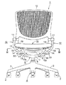
図1は、本発明を適用したリクライニング椅子の一実施形態を示す正面図、図2は、同じく側面図で、椅子(1)は、先端にキャスタ(2)が取付けられた放射方向を向く5本の脚杆(3)を有する脚体(4)と、その中心に立設された脚柱(5)と、この脚柱(5)の上端に前端部中央が取付けられた支基(6)とを備えている。
Hereinafter, embodiments of the present invention will be described with reference to the drawings.
FIG. 1 is a front view showing an embodiment of a reclining chair to which the present invention is applied, FIG. 2 is a side view of the same, and the chair (1) faces a radial direction in which a caster (2) is attached to the tip. A leg (4) having a leg rod (3), a pedestal (5) erected at the center thereof, and a support base (6) with the center of the front end attached to the upper end of the pedestal (5) ).
支基(6)は、脚柱(5)の上端に固着された、上面が開口する箱状の支基ベース(7)と、その上面を覆う、下面が開口された箱状の上カバー(8)とからなっている。 The support base (6) is fixed to the upper end of the pedestal (5) and has a box-like support base (7) with an open top surface, and a box-shaped upper cover with an open bottom surface covering the top surface ( 8).
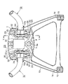
図3に示すように、脚柱(5)及びそれに固着された支基ベース(7)は、脚柱(5)内に収容されたロック付きガススプリング(9)のロック解除杆(9a)を、後記する操作機構(33)により押動させることにより、上下位置調節可能となっている。 As shown in FIG. 3, the pedestal (5) and the support base (7) fixed to the pedestal (5) are provided with a lock release rod (9a) of the gas spring with lock (9) housed in the pedestal (5). The vertical position can be adjusted by being pushed by an operation mechanism (33) described later.
(10)(10)は、左右1対の背凭れ支持杆で、側面視概ねくの字形をなすとともに、下端には、内向き水平の枢軸部(10a)が連設されている。 (10) and (10) are a pair of left and right back support rods, each having a generally U-shape when viewed from the side, and an inward horizontal pivot portion (10a) connected to the lower end.
左右の背凭れ支持杆(10)の上端に固着された左右方向を向く背凭れ支持部材(11)(11)の上端の上向突出片(図示略)には、背凭れ(12)における左右両側の下端部が嵌合され、図示しないねじにより固着されている。 The upper projecting pieces (not shown) of the upper ends of the back support members (11) and (11) facing the left and right directions fixed to the upper ends of the left and right back support rods (10) The lower ends on both sides are fitted and fixed by screws (not shown).
支基ベース(7)の前端には、斜め前上方を向くとともに、前方に向かうにしたがって外側方に拡開する平面視枠状の座支持フレーム(13)が一体的に連設され、この座支持フレーム(13)における左右の前端部上面には、図3及び図4に示すように、左右両側面に前後方向を向く1対の外向コ字状のガイド溝(14a)(14a)を有するガイド部材(14)が、ボルト(15)により固着されている。 At the front end of the support base (7), a seat support frame (13) in the form of a frame in plan view that extends obliquely forward and expands outward as it goes forward is integrally connected to this seat. As shown in FIGS. 3 and 4, a pair of outward U-shaped guide grooves (14a) (14a) facing the front-rear direction are formed on the upper surfaces of the left and right front end portions of the support frame (13). The guide member (14) is fixed by a bolt (15).
左右のガイド部材(14)には、座体(16)における合成樹脂よりなる座板(17)の前端部の両側部下面が、それに一体形成された前後方向を向くスライド部材(18)(18)における下面のあり溝状のスライド溝(18a)を、上記両ガイド溝(14a)に摺動可能に嵌合することにより、前後方向に移動可能に支持されている。 The left and right guide members (14) include slide members (18), (18) (18) (18) in which the lower surfaces of both sides of the front end portion of the seat plate (17) made of synthetic resin in the seat body (16) are integrally formed. ) Is supported so as to be movable in the front-rear direction by slidably fitting the groove-shaped slide groove (18a) on the lower surface in both guide grooves (14a).
座板(17)の左右両側の後端部に一体的に上向突設された左右1対の座支持片(19)(19)の上端は、左右の背凭れ支持部材(11)に枢着され、これにより、座体(16)の後端は、左右の背凭れ支持杆(10)により回動可能に吊支されている。 The upper ends of a pair of left and right seat support pieces (19) and (19), which are integrally projected upward at the rear end portions of the left and right sides of the seat plate (17), are pivoted to the left and right back support members (11). As a result, the rear end of the seat body (16) is pivotably supported by the left and right backrest support rods (10).
図3に示すように、支基ベース(7)の上面の凹部内の中央には、左右方向を向く内筒(20)と、それよりも大径かつ短寸の外筒(21)と、それらの間に固着されたトーションゴム(22)とからなる公知のゴムトーションユニット(23)が、外筒(21)が回り止めされて収容されている。 As shown in FIG. 3, in the center of the recess on the upper surface of the support base (7), an inner cylinder (20) facing in the left-right direction, an outer cylinder (21) having a larger diameter and shorter than that, A known rubber torsion unit (23) comprising a torsion rubber (22) fixed between them is accommodated with the outer cylinder (21) being prevented from rotating.
図5に示すように、ゴムトーションユニット(23)における内筒(20)の両側端部には、左右の背凭れ支持杆(10)の枢軸部(10a)の内端部が外嵌され、それらにピン(24)を圧入することにより、互いに相対回転不能に連結されている。 As shown in FIG. 5, the inner ends of the pivot portions (10a) of the left and right back support rods (10) are externally fitted to both ends of the inner cylinder (20) in the rubber torsion unit (23). By inserting a pin (24) into them, they are connected so as not to rotate relative to each other.
これにより、左右の背凭れ支持杆(10)及びそれに取付けられた背凭れ(12)には、内筒(20)がトーションゴム(22)を円周方向に弾性変形させる際に生じるねじり抵抗により、付勢力が付与される。
なお、ゴムトーションユニット(23)は、背凭れ支持杆(10)が常時前向きに付勢されるように、内筒(20)に初期付勢力を付与した状態で組付けられている。
As a result, the left and right backrest support ridges (10) and the backrest (12) attached thereto have a torsional resistance generated when the inner cylinder (20) elastically deforms the torsion rubber (22) in the circumferential direction. A biasing force is applied.
The rubber torsion unit (23) is assembled in a state where an initial urging force is applied to the inner cylinder (20) so that the backrest support ridge (10) is always urged forward.
左右の背凭れ支持杆(10)における枢軸部(10a)の内端部外周面の上半部には、枢軸部(10a)の軸線と直交する方向を向くフランジ状の突部(25)が一体的に形成され、その前方への突出部の下面と後方への突出部の下面には、前限用被ストッパ段部(25a)と、それよりも若干上方に位置する後限用被ストッパ段部(25b)とが形成されている。 In the upper half of the outer peripheral surface of the inner end portion of the pivot portion (10a) of the left and right back support rods (10), there are flange-like protrusions (25) facing in the direction perpendicular to the axis of the pivot portion (10a). The front limit stopper step (25a) is formed on the lower surface of the forward projecting portion and the lower surface of the rear projecting portion, and the rear limit stopper to be positioned slightly above it. A step portion (25b) is formed.
前限用被ストッパ段部(25a)は、支基ベース(7)の左右両側部上面の凹部(26)内に前後方向に移動可能に遊嵌され、支基ベース(7)の下面より挿入したボルト(27)により固定された前限用ストッパ部材(28)の上面に、常時当接するとともに、後限用被ストッパ段部(25b)は、支基ベース(7)の後部上面の後限用ストッパ面(29)に当接しうるようになっている。これにより、背凭れ支持杆(10)と背凭れ(12)の前後方向への最大傾動量が規制される。 The front limit stopper step (25a) is loosely fitted in the recesses (26) on the upper surfaces of the left and right sides of the support base (7) so as to be movable in the front-rear direction, and is inserted from the lower surface of the support base (7). The front limit stopper member (28) fixed by the bolt (27) is always in contact with the upper limit stopper member (28), and the rear limit stopper step (25b) is the rear limit of the rear upper surface of the support base (7). It can come into contact with the stopper surface (29). Thereby, the maximum tilting amount in the front-rear direction of the backrest support heel (10) and the backrest (12) is regulated.
前限用被ストッパ段部(25a)が前限用ストッパ部材(28)の上面に当接したとき、後限用被ストッパ段部(25b)と後限用ストッパ面(29)との間には、後方に開口する隙間(S)が形成されるようになっている。 When the front-stage stopper stepped portion (25a) abuts the upper surface of the front-end stopper member (28), the rear-limit stoppered step portion (25b) and the rear-end stopper surface (29) Is formed with a gap (S) that opens rearward.
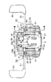
図6及び図7は、上記上カバー(8)を下方より見た分解斜視図と底面図を示す。 6 and 7 show an exploded perspective view and a bottom view of the upper cover (8) as viewed from below.
上カバー(8)の下面は、皿状に上方に凹ませてあり、その左右両側部の中央に形成された半円状の凹溝(30)を、上記左右の背凭れ支持杆(10)の枢軸部(10a)に上方から回動可能に嵌合し、かつ四隅部に設けた挿通孔(31)より挿入したボルト(図示略)を、支基ベース(7)の上面のめねじ孔(32)に螺合することにより、上カバー(8)は支基ベース(7)の上面に着脱可能に取付けられる。 The lower surface of the upper cover (8) is recessed upward in a dish shape, and the semicircular concave grooves (30) formed in the center of the left and right sides are provided with the left and right backrest support rods (10). A bolt (not shown) that is pivotally fitted to the pivot portion (10a) of the shaft and inserted from the insertion holes (31) provided at the four corners is a female screw hole on the upper surface of the support base (7). By screwing into (32), the upper cover (8) is detachably attached to the upper surface of the support base (7).
上カバー(8)の下面には、上記ガススプリング(9)のロック解除杆(9a)を押動させて脚柱(5)を伸縮させ、座体(16)の高さを調節するためのガススプリング操作機構(33)と、背凭れ支持杆(10)の傾動をロックしたり、ロックを解除したりして、背凭れ(12)の前後位置を調節する背凭れロック機構(34)とが、次のようにして組付けられている。 On the lower surface of the upper cover (8), the lock release rod (9a) of the gas spring (9) is pushed to extend and retract the pedestal (5) to adjust the height of the seat (16). A gas spring operating mechanism (33) and a backrest locking mechanism (34) that adjusts the back and forth position of the backrest (12) by locking and unlocking the tilt of the backrest support heel (10) However, it is assembled as follows.
ガススプリング操作機構(33)は、外側端に操作ハンドル(35)を有する左右方向を向く操作杆(36)と、この操作杆(36)の内端に前向きに突設された押動ロッド(37)と、この押動ロッド(37)と直交する左右方向を向き、外側端部が押動ロッド(37)により上向きに押動可能な、中間部に前後方向を向く回動軸(38)を有する作動杆(39)と、作動杆(39)の内側端に圧嵌された、上記ガススプリング(9)のロック解除杆(9a)を押動可能な上下方向を向くプッシュロッド(40)とを備えている。 The gas spring operating mechanism (33) includes an operating rod (36) having an operating handle (35) on the outer end and facing in the left-right direction, and a push rod (projecting forward) on the inner end of the operating rod (36). 37) and a rotating shaft (38) that faces in the left-right direction perpendicular to the push rod (37) and whose outer end can be pushed upward by the push rod (37), and that faces the middle portion in the front-rear direction. And a push rod (40) facing the up-and-down direction that can press the unlocking rod (9a) of the gas spring (9) press-fitted to the inner end of the operating rod (39) And.
操作杆(36)は、図8にも示すように、操作杆(36)の内端部に挿入された、外周の一部にスリット状の割り溝を有する支持部材(41)を、上カバー(8)における右方の前端寄りの側端部下面の凹部(42)に嵌挿したのち、支持部材(41)に連設された後方を向く取付片(41a)を、ボルト(43)をもって上カバー(8)の下面にねじ止めすることにより、上カバー(8)の下面に、支持部材(41)をもって回動可能に保持された状態で組付けられている。 As shown in FIG. 8, the operating rod (36) includes a support member (41) inserted into the inner end of the operating rod (36) and having a slit-shaped split groove on a part of the outer periphery. After inserting into the recess (42) on the lower surface of the side end near the front end on the right side in (8), the mounting piece (41a) connected to the support member (41) and facing backward is attached with the bolt (43). By being screwed to the lower surface of the upper cover (8), it is assembled to the lower surface of the upper cover (8) in a state of being rotatably supported by a support member (41).
上カバー(8)のやや中央寄りの前端部下面には、上記作動杆(39)を取付けるための支持片(44)(45)が、前後に若干離間して突設され、後部の支持片(45)には、後面が閉塞された正面視下向U字状の支持溝(46)が形成されている。 Support pieces (44) and (45) for mounting the operating rod (39) are provided on the lower surface of the front end of the upper cover (8) slightly closer to the center and project slightly apart from the front and rear. (45) is formed with a U-shaped support groove (46) facing downward in the front view with the rear surface closed.
作動杆(39)は、その回動軸(38)を、上記支持片(45)の支持溝(46)に、作動杆(39)の外側端部が押動ロッド(37)の上方に位置するように回動可能に嵌合したのち、両支持片(44)(45)の下端に当接させた支持板(47)の前端部を、前部の支持片(44)にボルト(48)をもって固定することにより、回動軸(38)を中心として上下に揺動しうるように、上カバー(8)の下面に組付けられている。 The operating rod (39) has its rotation shaft (38) positioned in the support groove (46) of the support piece (45) and the outer end of the operating rod (39) positioned above the push rod (37). The front end of the support plate (47) brought into contact with the lower ends of both support pieces (44) (45) is connected to the front support piece (44) with bolts (48 ) Is fixed to the lower surface of the upper cover (8) so that it can swing up and down about the rotation shaft (38).
なお、この組付後において、上カバー(8)を支基ベース(7)の上面に取付けた際、プッシュロッド(40)の下端が、ガススプリング(9)のロック解除杆(9a)の上端と近接して対向するようになっている。従って、操作ハンドル(35)を図6において上向きに回動させると、押動ロッド(37)により作動杆(39)が揺動させられて、プッシュロッド(40)が図6において下方に移動することにより、ロック解除杆(9a)の上端が押動され、ガススプリング(9)のロックが解除させられる。 After the assembly, when the upper cover (8) is attached to the upper surface of the support base (7), the lower end of the push rod (40) is the upper end of the lock release rod (9a) of the gas spring (9). It is designed to face each other in close proximity. Accordingly, when the operating handle (35) is rotated upward in FIG. 6, the operating rod (39) is swung by the push rod (37), and the push rod (40) is moved downward in FIG. As a result, the upper end of the lock release rod (9a) is pushed and the lock of the gas spring (9) is released.
上記背凭れロック機構(34)は、外側端に操作ハンドル(50)を有する長寸の操作杆(51)と、この操作杆(51)の内端部に固着された前方に長い左右1対の回動片(52)(52)と、上向きに凸円弧状に湾曲するワイヤ状の左右1対の作動ばね(53)(53)と、左右1対のロック部材(54)(54)とを備えている。 The backrest locking mechanism (34) includes a long operating rod (51) having an operating handle (50) on the outer end, and a pair of long left and right fronts fixed to the inner end of the operating rod (51). Rotating pieces (52), (52), a pair of left and right actuating springs (53), (53) curved in a convex arc shape upward, a pair of left and right locking members (54), (54), It has.
操作杆(51)は、上記ガススプリング操作機構(33)側の操作杆(36)と同様、中間部に挿入された支持部材(41)を、上カバー(8)の左方の側端部下面の凹部(42)に嵌挿し、取付片(41a)(図8参照)をボルト(43)により固定することにより、上カバー(8)の下面に、右方の操作杆(36)と同軸をなすように回動可能に組付けられている。 As with the operation rod (36) on the side of the gas spring operation mechanism (33), the operation rod (51) is configured so that the support member (41) inserted in the intermediate portion is connected to the left side end portion of the upper cover (8). Fit into the recess (42) on the lower surface and fix the mounting piece (41a) (see FIG. 8) with the bolt (43), so that it is coaxial with the right operation rod (36) on the lower surface of the upper cover (8). It is assembled so that it can rotate.
左右の作動ばね(53)の後端の外向折曲片(53a)は、それぞれ左右のロック部材(54)の中間部の左右方向を向く嵌合孔(図示略)に嵌合され、また同じく前端の内向折曲片(53b)は、左右の回動片(52)の前端部の嵌合孔(図示略)に嵌合されている。これにより、左右の回動片(52)と左右のロック部材(54)とは、作動ばね(53)を介して連係され、操作ハンドル(50)を図6において下方に回動操作したとき、ロック部材(54)は、作動ばね(53)により前方に移動させられるようになっている。 The outward bent pieces (53a) at the rear ends of the left and right actuating springs (53) are respectively fitted in fitting holes (not shown) facing the left and right in the middle part of the left and right lock members (54). The inwardly bent piece (53b) at the front end is fitted in a fitting hole (not shown) at the front end of the left and right rotating pieces (52). Thus, the left and right rotating pieces (52) and the left and right lock members (54) are linked via the operating spring (53), and when the operation handle (50) is rotated downward in FIG. The lock member (54) can be moved forward by the operating spring (53).
左右のロック部材(54)は、上カバー(8)の後端部の左右両側部下面に突設した支持片(55)(55)の下面に当接され、正面視倒立L字状をなす保持板(56)(56)の後端部を、ボルト(57)をもって上カバー(8)の下面に固定することにより、上カバー(8)の下面に前後方向に移動可能に組付けられている。 The left and right lock members (54) are in contact with the lower surfaces of the support pieces (55) and (55) projecting from the lower surfaces of the left and right sides of the rear end of the upper cover (8), and form an inverted L shape when viewed from the front. By fixing the rear end of the holding plate (56) (56) to the lower surface of the upper cover (8) with a bolt (57), it is assembled to the lower surface of the upper cover (8) so as to be movable in the front-rear direction. Yes.
この組付時において、作動ばね(53)は、上カバー(8)の下面に設けた前後方向を向くガイド溝(58)に遊嵌されるようになっている。 At the time of this assembly, the operating spring (53) is loosely fitted into a guide groove (58) facing the front-rear direction provided on the lower surface of the upper cover (8).
(59)は、クリックばね(ねじりコイルばね)で、左右方向の一方の足片(59a)を、上カバー(8)の前端部下面にボルト(60)により固定した係止片(61)の裏面に係止するとともに、他方の足片(59b)を、左方の回動片(52)の前端下部に嵌合して係止することにより、操作ハンドル(50)を、ほぼ水平をなす非操作位置と、下向きの操作位置とに節度感をもって回動させることができる。 Reference numeral (59) is a click spring (torsion coil spring). One of the left and right foot pieces (59a) is fixed to the lower surface of the front end of the upper cover (8) with a bolt (60). The operating handle (50) is made substantially horizontal by engaging the other foot piece (59b) with the lower part of the front end of the left rotating piece (52) and engaging it with the back surface. It can be rotated with a sense of moderation between the non-operation position and the downward operation position.
図9は、ガススプリング操作機構(33)及び背凭れロック機構(34)の各構成部材を組付けた後の上カバー(8)を、支基ベース(7)の上面に固定した際における図5と同じ部位の縦断側面図で、操作ハンドル(50)の非操作時を示している。 FIG. 9 is a view when the upper cover (8) after assembling the constituent members of the gas spring operating mechanism (33) and the backrest locking mechanism (34) is fixed to the upper surface of the support base (7). 5 is a vertical side view of the same part as FIG. 5 and shows the non-operating state of the operation handle (50).
この際には、上カバー(8)の後端部下面に組付けられたロック部材(54)は、操作杆(51)及び回動片(52)が回動しないため、作動ばね(53)の付勢力により、後限に位置し、後限用被ストッパ段部(25b)と後限用ストッパ面(29)との間の隙間(S)より後方に退避している。 At this time, the lock member (54) assembled to the lower surface of the rear end portion of the upper cover (8) does not rotate the operating rod (51) and the rotating piece (52). Due to the urging force, it is located at the rear limit and retracts backward from the gap (S) between the rear limit stopper stepped portion (25b) and the rear limit stopper surface (29).
従って、背凭れ支持杆(10)及び背凭れ(12)は、前限用被ストッパ段部(25a)と後限用被ストッパ段部(25b)とが、それぞれ前限用ストッパ部材(28)と後限用ストッパ面(29)の上面と当接する範囲内で、前後方向にリクライニングすることができる。 Accordingly, the backrest supporting heel (10) and backrest (12) have a front limit stopper stepped portion (25a) and a rear limit stopper stepped portion (25b), respectively. And reclining in the front-rear direction within a range in contact with the upper surface of the rear limit stopper surface (29).
操作ハンドル(50)を下向きに回動すると、図10に示すように、操作杆(51)及び回動片(52)が側面視反時計方向に回動することにより、作動ばね(53)が前方に引っ張られ、ロック部材(54)は前方に移動する。これにより、背凭れ(12)が前限まで移動しているときに、ロック部材(54)の前端部が隙間(S)内に進入し、背凭れ支持杆(10)の前後方向の回動がロックされるため、背凭れ(12)のリクライニングも不能となる。 When the operating handle (50) is rotated downward, as shown in FIG. 10, the operating rod (51) and the rotating piece (52) are rotated counterclockwise as viewed from the side, whereby the operating spring (53) is moved. Pulled forward, the lock member (54) moves forward. Thereby, when the backrest (12) is moved to the front limit, the front end portion of the lock member (54) enters the gap (S), and the backrest support rod (10) rotates in the front-rear direction. Is locked, so reclining of the backrest (12) becomes impossible.
なお、図示は省略するが、上カバー(8)を支基ベース(7)に取付けた状態で、ガススプリング操作機構(33)側の操作ハンドル(35)を上向きに回動すると、上述したように、操作杆(36)の押動ロッド(37)が上向きに回動し、作動杆(39)におけるプッシュロッド(40)が下向きに移動して、ガススプリング(9)のロック解除杆(9a)を押動することにより、座体(10)の高さを調節することができる。 Although not shown, when the operation handle (35) on the gas spring operation mechanism (33) side is turned upward with the upper cover (8) attached to the support base (7), as described above. In addition, the push rod (37) of the operating rod (36) rotates upward, the push rod (40) of the operating rod (39) moves downward, and the unlocking rod (9a) of the gas spring (9) is moved. ) Can be adjusted to adjust the height of the seat (10).
以上説明したように、上記実施形態の椅子(1)においては、座体(16)の高さを調節するためのガススプリング操作機構(33)を構成している操作杆(36)や作動杆(39)は、上カバー(8)の下面にボルト(43)(48)により固定された支持部材(41)と支持板(47)に保持されて落下が防止され、また背凭れ(12)の傾動をロックまたはロック解除して、その前後位置を調節する背凭れロック機構(34)を構成している操作杆(51)やロック部材(54)等も、上カバー(8)の下面にボルト(43)(57)により固定された支持部材(41)と保持板(56)により落下が防止されているので、ガススプリング操作機構(33)及び背凭れロック機構(34)を構成する全ての部材を、上カバー(8)の下面に集約して組付けることが可能となる。 As described above, in the chair (1) of the above-described embodiment, the operating rod (36) and the operating rod constituting the gas spring operating mechanism (33) for adjusting the height of the seat (16). (39) is held by a support member (41) and a support plate (47) fixed to the lower surface of the upper cover (8) by bolts (43) and (48) to prevent falling, and the backrest (12) An operation rod (51), a lock member (54), etc. that constitute a backrest lock mechanism (34) that locks or unlocks the tilting and adjusts the front-rear position thereof are also provided on the lower surface of the upper cover (8). Since the fall is prevented by the support member (41) and the holding plate (56) fixed by the bolts (43) and (57), all of which constitutes the gas spring operation mechanism (33) and the backrest lock mechanism (34) These members can be assembled and assembled on the lower surface of the upper cover (8).
その結果、支基ベース(7)に各部材を集約して組付けた従来のものに比して、その構造が簡素化し、製造コストを低減することができる。
また、支基ベース(7)上の狭いスペースに多くの部品を組付ける必要がないので、組付けが容易となり、作業効率が向上する
As a result, the structure can be simplified and the manufacturing cost can be reduced as compared with the conventional structure in which the members are assembled and assembled on the support base (7).
Moreover, since it is not necessary to assemble many parts in a narrow space on the support base (7), the assemble becomes easy and the work efficiency is improved.
さらに、脚体(3)に支基ベース(7)を組付けたり、支基ベース(7)上にゴムトーションユニット(23)や背凭れ支持杆(10)を組付ける工程と、上カバー(8)にガススプリング操作機構(33)及び背凭れロック機構(34)を組付ける工程とを別々に行うことが可能となるので、全ての部材を予め別工程で組付けておいた上カバー(8)を、単に支基ベース(7)の上面に固定するだけで、ガススプリング操作機構(33)や背凭れロック機構(34)の支基(6)への組付けが完了し、組立効率が向上する。 In addition, the support base (7) is assembled to the leg (3), the rubber torsion unit (23) and the backrest support rod (10) are assembled on the support base (7), and the upper cover ( 8) Since the process of assembling the gas spring operating mechanism (33) and the backrest locking mechanism (34) can be performed separately, the upper cover (all members previously assembled in separate processes) 8) is simply fixed to the upper surface of the support base (7), and the assembly of the gas spring operating mechanism (33) and the backrest lock mechanism (34) to the support base (6) is completed. Will improve.
上カバー(8)を支基ベース(7)より取外すだけで、ガススプリング操作機構(33)や背凭れロック機構(34)の部品交換やメンテナンスを行いうるので、それらの作業性が良好となる。 By simply removing the upper cover (8) from the support base (7), parts replacement and maintenance of the gas spring operating mechanism (33) and backrest locking mechanism (34) can be performed, so their workability is improved. .
(1)リクライニング椅子
(2)キャスタ
(3)脚杆
(4)脚体
(5)脚柱
(6)支基
(7)支基ベース
(8)上カバー
(9)ガススプリング
(9a)ロック解除杆
(10)背凭れ支持杆
(10a)枢軸部
(11)背凭れ支持部材
(12)背凭れ
(13)座支持フレーム
(14)ガイド部材
(14a)ガイド溝
(15)ボルト
(16)座体
(17)座板
(18)スライド部材
(18a)スライド溝
(19)座支持片
(20)内筒
(21)外筒
(22)トーションゴム
(23)ゴムトーションユニット
(24)ピン
(25)突部
(25a)前限用被ストッパ段部
(25b)後限用被ストッパ段部
(26)凹部
(27)ボルト
(28)前限用ストッパ部材
(29)後限用ストッパ面
(30)凹溝
(31)挿通孔
(32)めねじ孔
(33)ガススプリング操作機構
(34)背凭れロック機構
(35)操作ハンドル
(36)操作杆
(37)押動ロッド
(38)回動軸
(39)作動杆
(40)プッシュロッド
(41)支持部材
(41a)取付片
(42)凹部
(43)ボルト
(44)(45)支持片
(46)支持溝
(47)支持板
(48)ボルト
(50)操作ハンドル
(51)操作杆
(52)回動片
(53)作動ばね
(53a)外向折曲片
(53b)内向折曲片
(54)ロック部材
(55)支持片
(56)保持板
(57)ボルト
(58)ガイド溝
(59)クリックばね
(59a)(59b)足片
(60)ボルト
(61)係止片
(S)隙間
(1) Reclining chair
(2) Casters
(3) Footpad
(4) Leg
(5) pedestal
(6) Support base
(7) Support base
(8) Upper cover
(9) Gas spring
(9a) Unlock 杆
(10) Back support
(10a) Axis
(11) Back support member
(12) Backrest
(13) Seat support frame
(14) Guide member
(14a) Guide groove
(15) Bolt
(16) Seat
(17) Seat plate
(18) Slide member
(18a) Slide groove
(19) Seat support piece
(20) Inner cylinder
(21) Outer cylinder
(22) Torsion rubber
(23) Rubber torsion unit
(24) Pin
(25) Projection
(25a) Stopped stepped part for front limit
(25b) Stopped stepped part for rear limit
(26) Recess
(27) Bolt
(28) Front limit stopper member
(29) Rear limit stopper surface
(30) Concave groove
(31) Insertion hole
(32) Female thread hole
(33) Gas spring operation mechanism
(34) Backrest lock mechanism
(35) Operation handle
(36) Operation 杆
(37) Push rod
(38) Rotating shaft
(39) Working rod
(40) Push rod
(41) Support member
(41a) Mounting piece
(42) Recess
(43) Bolt
(44) (45) Support piece
(46) Support groove
(47) Support plate
(48) Bolt
(50) Operation handle
(51) Operation 杆
(52) Rotating piece
(53) Actuating spring
(53a) Outward bending piece
(53b) Inward bending piece
(54) Lock member
(55) Support piece
(56) Retaining plate
(57) Bolt
(58) Guide groove
(59) Click spring
(59a) (59b) Foot piece
(60) Bolt
(61) Locking piece
(S) Gap
Claims (5)
The chair according to claim 4, wherein an operation rod of the backrest lock mechanism is supported so as to be coaxial with the operation rod of the operation mechanism.
Priority Applications (1)
| Application Number | Priority Date | Filing Date | Title |
|---|---|---|---|
| JP2006114456A JP4842003B2 (en) | 2006-04-18 | 2006-04-18 | Chair |
Applications Claiming Priority (1)
| Application Number | Priority Date | Filing Date | Title |
|---|---|---|---|
| JP2006114456A JP4842003B2 (en) | 2006-04-18 | 2006-04-18 | Chair |
Publications (2)
| Publication Number | Publication Date |
|---|---|
| JP2007282892A JP2007282892A (en) | 2007-11-01 |
| JP4842003B2 true JP4842003B2 (en) | 2011-12-21 |
Family
ID=38755192
Family Applications (1)
| Application Number | Title | Priority Date | Filing Date |
|---|---|---|---|
| JP2006114456A Expired - Fee Related JP4842003B2 (en) | 2006-04-18 | 2006-04-18 | Chair |
Country Status (1)
| Country | Link |
|---|---|
| JP (1) | JP4842003B2 (en) |
Families Citing this family (3)
| Publication number | Priority date | Publication date | Assignee | Title |
|---|---|---|---|---|
| JP5187738B2 (en) * | 2008-03-05 | 2013-04-24 | タカノ株式会社 | Cover mounting structure |
| JP5571354B2 (en) * | 2009-10-30 | 2014-08-13 | 株式会社イトーキ | Rocking chair |
| CN114027658B (en) * | 2021-12-03 | 2024-06-07 | 鹤山市四方家具有限公司 | Engineering chair |
Family Cites Families (7)
| Publication number | Priority date | Publication date | Assignee | Title |
|---|---|---|---|---|
| JPS6072644A (en) * | 1983-09-30 | 1985-04-24 | Toshiba Corp | Production of low melting alloy wire for sealing fluorescent lamp |
| JP2603980B2 (en) * | 1988-01-13 | 1997-04-23 | 株式会社東芝 | High heat-insulating cast iron |
| JPH0717767B2 (en) * | 1988-11-24 | 1995-03-01 | 新神戸電機株式会社 | Method for manufacturing epoxy resin laminate |
| JP2001057917A (en) * | 1999-08-20 | 2001-03-06 | Uchida Yoko Co Ltd | Seal sliding structure for office chairs |
| JP4727805B2 (en) * | 2000-11-06 | 2011-07-20 | 株式会社岡村製作所 | Control lever structure in a chair |
| JP2004033449A (en) * | 2002-07-03 | 2004-02-05 | Kokuyo Co Ltd | Lever attaching structure for chair |
| JP4473590B2 (en) * | 2004-01-28 | 2010-06-02 | 株式会社岡村製作所 | Reclining chair |
-
2006
- 2006-04-18 JP JP2006114456A patent/JP4842003B2/en not_active Expired - Fee Related
Also Published As
| Publication number | Publication date |
|---|---|
| JP2007282892A (en) | 2007-11-01 |
Similar Documents
| Publication | Publication Date | Title |
|---|---|---|
| US6213552B1 (en) | Multi-position chair control mechanism for synchronously adjusting the seat and backrest of a chair | |
| JP4842003B2 (en) | Chair | |
| JP2008194229A (en) | Height adjuster of armrest in chair | |
| JP5917926B2 (en) | Operation lever device and chair provided with the same | |
| JP4908826B2 (en) | Reclining chair | |
| JP4908954B2 (en) | Front / rear position adjustment device for seat body in chair | |
| JP5616406B2 (en) | Chair | |
| JP2004049717A (en) | Device for inclining backrest or the like for chair | |
| JP4695165B2 (en) | Seat front / rear sliding device in a chair | |
| JP4750535B2 (en) | Backrest locking device in reclining chair | |
| JP4896611B2 (en) | Operation lever device in a chair | |
| JP4636843B2 (en) | Seat front / rear sliding device in a chair | |
| JP5989999B2 (en) | Chair | |
| JP5563631B2 (en) | Chair | |
| JP5881239B2 (en) | Chair and gas cylinder device thereof | |
| JP2011092475A (en) | Rocking chair | |
| JP5026782B2 (en) | Chair | |
| JP3757332B2 (en) | Chair gas spring operating device | |
| JP4384003B2 (en) | Gas spring operating device for chair | |
| JP2006102148A5 (en) | ||
| JP5008993B2 (en) | Chair | |
| JP2019103676A (en) | Chair | |
| JP5154091B2 (en) | Chair armrest equipment | |
| JP5106871B2 (en) | Chair | |
| JP2006102147A (en) | Seat forward/backward sliding device for chair |
Legal Events
| Date | Code | Title | Description |
|---|---|---|---|
| A621 | Written request for application examination |
Free format text: JAPANESE INTERMEDIATE CODE: A621 Effective date: 20090406 |
|
| A977 | Report on retrieval |
Free format text: JAPANESE INTERMEDIATE CODE: A971007 Effective date: 20110926 |
|
| TRDD | Decision of grant or rejection written | ||
| A01 | Written decision to grant a patent or to grant a registration (utility model) |
Free format text: JAPANESE INTERMEDIATE CODE: A01 Effective date: 20111004 |
|
| A01 | Written decision to grant a patent or to grant a registration (utility model) |
Free format text: JAPANESE INTERMEDIATE CODE: A01 |
|
| A61 | First payment of annual fees (during grant procedure) |
Free format text: JAPANESE INTERMEDIATE CODE: A61 Effective date: 20111005 |
|
| R150 | Certificate of patent or registration of utility model |
Ref document number: 4842003 Country of ref document: JP Free format text: JAPANESE INTERMEDIATE CODE: R150 |
|
| FPAY | Renewal fee payment (event date is renewal date of database) |
Free format text: PAYMENT UNTIL: 20141014 Year of fee payment: 3 |
|
| R250 | Receipt of annual fees |
Free format text: JAPANESE INTERMEDIATE CODE: R250 |
|
| R250 | Receipt of annual fees |
Free format text: JAPANESE INTERMEDIATE CODE: R250 |
|
| R250 | Receipt of annual fees |
Free format text: JAPANESE INTERMEDIATE CODE: R250 |
|
| R250 | Receipt of annual fees |
Free format text: JAPANESE INTERMEDIATE CODE: R250 |
|
| R250 | Receipt of annual fees |
Free format text: JAPANESE INTERMEDIATE CODE: R250 |
|
| S533 | Written request for registration of change of name |
Free format text: JAPANESE INTERMEDIATE CODE: R313533 |
|
| R350 | Written notification of registration of transfer |
Free format text: JAPANESE INTERMEDIATE CODE: R350 |
|
| R250 | Receipt of annual fees |
Free format text: JAPANESE INTERMEDIATE CODE: R250 |
|
| R250 | Receipt of annual fees |
Free format text: JAPANESE INTERMEDIATE CODE: R250 |
|
| R250 | Receipt of annual fees |
Free format text: JAPANESE INTERMEDIATE CODE: R250 |
|
| LAPS | Cancellation because of no payment of annual fees |