JP4833143B2 - Substrate processing equipment - Google Patents
Substrate processing equipment Download PDFInfo
- Publication number
- JP4833143B2 JP4833143B2 JP2007110513A JP2007110513A JP4833143B2 JP 4833143 B2 JP4833143 B2 JP 4833143B2 JP 2007110513 A JP2007110513 A JP 2007110513A JP 2007110513 A JP2007110513 A JP 2007110513A JP 4833143 B2 JP4833143 B2 JP 4833143B2
- Authority
- JP
- Japan
- Prior art keywords
- rotating shaft
- processing chamber
- electrode
- substrate
- processing
- Prior art date
- Legal status (The legal status is an assumption and is not a legal conclusion. Google has not performed a legal analysis and makes no representation as to the accuracy of the status listed.)
- Active
Links
Images


Description
本発明は基板処理装置に係り、特にプラズマを利用してシリコンウエハ等の被処理基板に所定の処理を行う基板処理装置に関する。 The present invention relates to a substrate processing apparatus, and more particularly to a substrate processing apparatus that performs predetermined processing on a substrate to be processed such as a silicon wafer using plasma.
図5を用いて従来の基板処理装置を説明する。ここでは、バッチ式のプラズマプロセスを用いて複数の被処理基板を一括してプラズマ処理する縦型処理炉を一例として説明する。 A conventional substrate processing apparatus will be described with reference to FIG. Here, a vertical processing furnace that performs plasma processing of a plurality of substrates to be processed using a batch type plasma process will be described as an example.
縦型処理炉には、開口部220を有する処理室201と、処理室201内にガスを供給するガス導入ポート320と、処理室201内を排気する排気管317及び真空ポンプ319とが設けられており、処理室201はガスを供給しつつ排気するように構成されている。
The vertical processing furnace is provided with a
処理室201の開口部220から基板保持具としてのボート217が処理室201内に挿入されるようになっており、ボート217は処理室201内で複数のウエハ200を保持するように構成されている。
A
ボート217にはウエハ200を載置する板状の第1サセプタ電極305及び第2サセプタ電極306が交互に積層されており、第1、第2サセプタ電極305、306はその電極間でプラズマを発生できるように構成されている。ボート217は回転板としてのキャップ受309上に載置されている。キャップ受309にはモータ367により回転駆動される回転軸366が連結されており、回転軸366はボート217を処理室201内で回転自在に支持できるように構成されている。
In the
また、回転軸366は、処理室201の開口部220を塞ぐ蓋体としてのシールキャップ219に磁気シール369を介して軸支されている。シールキャップ219はボート217を処理室201内に挿入したとき処理室201を気密に閉塞するとともに、回転軸366を回転自在に軸支するように構成されている。
The rotating
前述したキャップ受309の下側に、キャップ受309と電気的に絶縁された端子受351、352が設けられており、端子受351、352は高周波(RF)フィーダ353、354を介して第1サセプタ電極305及び第2サセプタ電極306に電気的に接続されるように構成されている。
シールキャップ219の下方には、ガイド軸365、365に嵌合された可動板364が配設されており、可動板364はガイド軸365、365によりシールキャップ219に対して上下移動自在に支持されるように構成されている。シールキャップ219と可動板364との間にはシリンダ363が設けられており、シリンダ363は可動板364を上下移動させるように構成されている。
A
可動板364にはシールキャップ219を貫通する第1、第2RF導入端子361、362が設けられており、処理室201の内部側の第1、第2RF導入端子361、362は、シリンダ363による可動板364の上下移動に伴ってシールキャップ219から出没して端子受351、352に接触、非接触するように構成されている。
The
シールキャップ219及び可動板364との間には、第1、第2RF導入端子361、
362を囲むようにフランジ付きのベローズ355、355及び絶縁シール368、368が設けられており、フランジ付きのベローズ355、355及び絶縁シール368、368は、第1、第2RF導入端子361、362の上下移動を、シールキャップ219及び可動板364との電気的絶縁を保持しつつ気密に行えるように構成されている。
Between the
Flanged
処理室201の外部側の第1、第2RF導入端子361、362には整合器316を介して発振器315が接続されており、発振器315は、第1、第2RF導入端子361、362、端子受351、352、RFフィーダ353、354を介して、処理室201内の第1、第2サセプタ電極305、306にRF電力をそれぞれ印加できるよう構成されている。
An
このような構成において、RF電力を第1、第2サセプタ電極305、306に印加してプラズマを生成するときは、ボート217の回転を停止した状態で、シリンダ363の動作により第1、第2RF導入端子361、362をボート217のキャップ受309の下面に設けられた端子受351、352に接触させて、RF電力をサセプタ電極305、306に通電可能な状態とする。RF電力をサセプタ電極305、306に通電可能な状態とした後、発振器315の出力する交流電力を整合器316を介してサセプタ電極305、306間に供給する。RF電力は端子受351、352を介して各サセプタ電極305、306に印加され、サセプタ電極305、306間にプラズマが生成される。サセプタ電極305、306間に生成されたこのプラズマによりウエハ200が処理される。
In such a configuration, when RF power is applied to the first and
また、プラズマを生成しないときは、ボート217全体を回転させた状態でウエハ200が処理される。ボート217を回転させることで、処理室201内のガス流れが均一になりウエハ200の処理の均一性が改善される。
When plasma is not generated, the
しかしながら、上述した従来技術では、プラズマ生成時に基板保持具の回転を停止するため、被処理基板のプラズマ処理の均一性が悪化し、面内均一性が低下するという問題があった。 However, in the above-described prior art, since the rotation of the substrate holder is stopped when plasma is generated, there is a problem that uniformity of plasma processing of the substrate to be processed is deteriorated and in-plane uniformity is lowered.
本発明の課題は、上述した従来技術の問題点を解消して、被処理基板のプラズマ処理の面内均一性を向上することが可能な基板処理装置を提供することにある。 An object of the present invention is to provide a substrate processing apparatus capable of solving the above-described problems of the prior art and improving the in-plane uniformity of plasma processing of a substrate to be processed.
本発明の第1の態様によれば、開口部を有し内部に処理室を形成する処理室と、前記開口部から前記処理室内に挿入され、被処理基板を保持する基板保持具と、前記基板保持具を支持するとともに前記開口部を気密に閉塞する蓋体と、前記処理室内にガスを供給するガス供給手段と、前記処理室内を排気する排気手段と、前記基板保持具に積層されるプラズマ生成用の少なくとも1対の電極であって、該電極間に前記被処理基板が配置される第1電極及び第2電極と、前記蓋体を貫通して前記処理室内で前記基板保持具を回転自在に支持するための回転軸と、前記回転軸の中を通って前記処理室の内部に導入され前記第1電極と前記第2電極とにそれぞれ電気的に接続される第1電力供給ライン及び第2電力供給ラインと、前記回転軸の中を通って前記処理室の外部に導出される前記第1電力供給ライン及び第2電力供給ラインにそれぞれ接続される第1回転コンデンサ及び第2回転コンデンサと、前記第1回転コンデンサ及び第2回転コンデンサを介して、前記第1電極及び第2電極に異なる位相の高周波電力を別々に供給する高周波電力供給手段と、を備えた基板処理装置が提供される。 According to the first aspect of the present invention, a processing chamber having an opening and forming a processing chamber therein, a substrate holder inserted into the processing chamber from the opening and holding the substrate to be processed, A lid that supports the substrate holder and hermetically closes the opening, a gas supply unit that supplies gas into the process chamber, an exhaust unit that exhausts the process chamber, and a substrate holder are stacked. At least one pair of electrodes for generating plasma, the first electrode and the second electrode on which the substrate to be processed is disposed between the electrodes, and the substrate holder in the processing chamber through the lid A rotating shaft for rotatably supporting, and a first power supply line that is introduced into the processing chamber through the rotating shaft and electrically connected to the first electrode and the second electrode, respectively. And the second power supply line and the rotating shaft A first rotating capacitor and a second rotating capacitor connected to the first power supply line and the second power supply line led out of the processing chamber, respectively, and the first rotating capacitor and the second rotating capacitor. And a high-frequency power supply means for separately supplying high-frequency power having different phases to the first electrode and the second electrode.
本発明の第2の態様によれば、開口部を有し内部に処理室を形成する処理容器と、前記
処理室内にガスを供給するガス供給手段と、前記処理室内を排気する排気手段と、前記開口部から前記処理室内に挿入され被処理基板を保持する基板保持具と、前記基板保持具に積層されるプラズマ生成用の少なくとも1対の電極であって、該電極間に前記被処理基板が配置される第1電極及び第2電極と、前記基板保持具を前記処理室内で回転自在に支持するための筒状の回転軸と、前記筒状の回転軸を回転自在に軸支し前記開口部を閉塞する蓋体と、前記筒状の回転軸内の中心に挿通されて前記処理室の内部で前記第1電極に電気的に接続される導電性の第1回転軸と、前記第1回転軸を同心状に囲むように前記筒状の回転軸内に挿通されて前記第2電極に電気的に接続される導電性で中空の第2回転軸と、前記第1回転軸と第2回転軸との間、及び第2回転軸と前記筒状の回転軸との間を絶縁する絶縁体と、前記第1回転軸及び前記第2回転軸を介して第1電極及び前記第2電極間に異なる位相の高周波電力を別々に供給する高周波電力供給手段と、を備えた基板処理装置が提供される。
According to the second aspect of the present invention, a processing container having an opening and forming a processing chamber therein, a gas supply means for supplying a gas into the processing chamber, an exhaust means for exhausting the processing chamber, A substrate holder inserted into the processing chamber from the opening to hold the substrate to be processed, and at least one pair of plasma generating electrodes stacked on the substrate holder, the substrate to be processed being interposed between the electrodes The first and second electrodes are arranged, a cylindrical rotating shaft for rotatably supporting the substrate holder in the processing chamber, and the cylindrical rotating shaft is rotatably supported by the shaft. A lid that closes the opening; a conductive first rotating shaft that is inserted through the center of the cylindrical rotating shaft and is electrically connected to the first electrode inside the processing chamber; The second rotating shaft is inserted into the cylindrical rotating shaft so as to concentrically surround the rotating shaft. Conductive and hollow second rotating shaft electrically connected to the pole, insulating between the first rotating shaft and the second rotating shaft, and between the second rotating shaft and the cylindrical rotating shaft And a high-frequency power supply means for separately supplying high-frequency power having different phases between the first electrode and the second electrode via the first rotating shaft and the second rotating shaft. An apparatus is provided.
本発明によれば被処理基板のプラズマ処理の面内均一性を向上することができる。 According to the present invention, the in-plane uniformity of the plasma processing of the substrate to be processed can be improved.
次に、本発明の好ましい実施の形態を説明する。
本発明の好ましい実施の形態では、ウエハが載置される第1、第2サセプタ電極をボートに積載し、ボートに連結される回転軸を回転させ、処理ガスがウエハに対して均一に流れるようにした。
第1、第2サセプタ電極へ電力供給を行うにあたり、第1、第2サセプタ電極に第1、第2回転コンデンサを介して、異なる位相の高周波電力を別々に供給することにより、ウエハを回転しながら高密度プラズマで処理できるようにした。
また、ボートに連結される回転軸を筒状の回転軸として、この筒状の回転軸内に相互に絶縁された導電性の第1、第2回転軸を通し、これら第1、第2回転軸を介して第1、第2サセプタ電極間に異なる位相の高周波電力を別々に供給することにより、ウエハを回転しながら高密度プラズマで処理できるようにした。
Next, a preferred embodiment of the present invention will be described.
In a preferred embodiment of the present invention, the first and second susceptor electrodes on which a wafer is placed are loaded on a boat, and a rotating shaft connected to the boat is rotated so that the processing gas flows uniformly with respect to the wafer. I made it.
In supplying power to the first and second susceptor electrodes, the wafer is rotated by separately supplying high-frequency power of different phases to the first and second susceptor electrodes via the first and second rotating capacitors. While being able to process with high density plasma.
Further, the rotating shaft connected to the boat is a cylindrical rotating shaft, and the first and second rotating shafts that are electrically insulated from each other are passed through the cylindrical rotating shaft. By separately supplying high-frequency power having different phases between the first and second susceptor electrodes via the shaft, the wafer can be processed with high-density plasma while rotating.
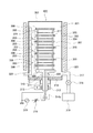
本発明を実施するための最良の形態において、基板処理装置は、一例として、半導体装置(IC)の製造方法における処理工程を実施する半導体製造装置として構成されている。尚、以下の説明では、基板処理装置として基板に酸化、エッチング、拡散処理やCVD処理などを行なう縦型の装置(以下、単に処理装置という)を適用した場合について述べる。図2は、本発明に適用される処理装置の斜透視図として示されている。また、図3は図2に示す処理装置の側面透視図である。 In the best mode for carrying out the present invention, as an example, the substrate processing apparatus is configured as a semiconductor manufacturing apparatus that performs processing steps in a method of manufacturing a semiconductor device (IC). In the following description, a case where a vertical apparatus (hereinafter simply referred to as a processing apparatus) that performs oxidation, etching, diffusion processing, CVD processing, or the like is applied to the substrate as the substrate processing apparatus will be described. FIG. 2 is shown as a perspective view of a processing apparatus applied to the present invention. FIG. 3 is a side perspective view of the processing apparatus shown in FIG.
図2および図3に示されているように、シリコン等からなるウエハ(被処理基板)200を収納したウエハキャリアとしてフープ(基板収容器。以下ポッドという。)110が使用されている本発明の処理装置100は、筐体111を備えている。筐体111の正面壁111aの正面前方部にはメンテナンス可能なように設けられた開口部としての正面メンテナンス口103が開設され、この正面メンテナンス口103を開閉する正面メンテナンス扉104、104がそれぞれ建て付けられている。
As shown in FIGS. 2 and 3, a hoop (substrate container; hereinafter referred to as a pod) 110 is used as a wafer carrier containing a wafer (substrate to be processed) 200 made of silicon or the like. The
筐体111の正面壁111aにはポッド搬入搬出口(基板収容器搬入搬出口)112が筐体111の内外を連通するように開設されており、ポッド搬入搬出口112はフロントシャッタ(基板収容器搬入搬出口開閉機構)113によって開閉されるようになっている。
A pod loading / unloading port (substrate container loading / unloading port) 112 is opened on the
ポッド搬入搬出口112の正面前方側にはロードポート(基板収容器受渡し台)114が設置されており、ロードポート114はポッド110を載置されて位置合わせするよう
に構成されている。ポッド110はロードポート114上に工程内搬送装置(図示せず)によって搬入され、かつまた、ロードポート114上から搬出されるようになっている。
A load port (substrate container delivery table) 114 is installed in front of the front side of the pod loading / unloading
筐体111内の前後方向の略中央部における上部には、回転式ポッド棚(基板収容器載置棚)105が設置されており、回転式ポッド棚105は複数個のポッド110を保管するように構成されている。すなわち、回転式ポッド棚105は垂直に立設されて水平面内で間欠回転される支柱116と、支柱116に上中下段の各位置において放射状に支持された複数枚の棚板(基板収容器載置台)117とを備えており、複数枚の棚板117はポッド110を複数個宛それぞれ載置した状態で保持するように構成されている。
A rotary pod shelf (substrate container mounting shelf) 105 is installed at an upper portion of the
筐体111内におけるロードポート114と回転式ポッド棚105との間には、ポッド搬送装置(基板収容器搬送装置)118が設置されており、ポッド搬送装置118は、ポッド110を保持したまま昇降可能なポッドエレベータ(基板収容器昇降機構)118aと搬送機構としてのポッド搬送機構(基板収容器搬送機構)118bとで構成されており、ポッド搬送装置118はポッドエレベータ118aとポッド搬送機構118bとの連続動作により、ロードポート114、回転式ポッド棚105、ポッドオープナ(基板収容器蓋体開閉機構)121との間で、ポッド110を搬送するように構成されている。
A pod transfer device (substrate container transfer device) 118 is installed between the
筐体111内の前後方向の略中央部における下部には、サブ筐体119が後端にわたって構築されている。サブ筐体119の正面壁119aにはウエハ200をサブ筐体119内に対して搬入搬出するためのウエハ搬入搬出口(基板搬入搬出口)120が一対、垂直方向に上下二段に並べられて開設されており、上下段のウエハ搬入搬出口120、120には一対のポッドオープナ121、121がそれぞれ設置されている。
A sub-housing 119 is constructed across the rear end of the lower portion of the
ポッドオープナ121はポッド110を載置する載置台122、122と、ポッド110のキャップ(蓋体)を着脱するキャップ着脱機構(蓋体着脱機構)123、123とを備えている。ポッドオープナ121は載置台122に載置されたポッド110のキャップをキャップ着脱機構123によって着脱することにより、ポッド110のウエハ出し入れ口を開閉するように構成されている。
The
サブ筐体119はポッド搬送装置118や回転式ポッド棚105の設置空間から流体的に隔絶された移載室124を構成している。移載室124の前側領域にはウエハ移載機構(基板移載機構)125が設置されており、ウエハ移載機構125は、ウエハ200を水平方向に回転ないし直動可能なウエハ移載装置(基板移載装置)125aおよびウエハ移載装置125aを昇降させるためのウエハ移載装置エレベータ(基板移載装置昇降機構)125bとで構成されている。図2に模式的に示されているようにウエハ移載装置エレベータ125bは、耐圧の筐体111右側端部とサブ筐体119の移載室124前方領域右端部との間に設置されている。これら、ウエハ移載装置エレベータ125bおよびウエハ移載装置125aの連続動作により、ウエハ移載装置125aのツイーザ(基板保持体)125cをウエハ200の載置部として、ボート(基板保持具)217に対してウエハ200を装填(チャージング)および脱装(ディスチャージング)するように構成されている。
The sub-housing 119 constitutes a
移載室124の後側領域には、ボート217を収容して待機させる待機部126が構成されている。待機部126の上方には、処理炉202が設けられている。処理炉202の下端部は、炉口シャッタ(炉口開閉機構)147により開閉されるように構成されている。
In the rear region of the
図2に模式的に示されているように、耐圧の筐体111右側端部とサブ筐体119の待機部126右端部との間にはボート217を昇降させるためのボートエレベータ(基板保
持具昇降機構)115が設置されている。ボートエレベータ115の昇降台に連結された連結具としてのアーム128には蓋体としてのシールキャップ219が水平に据え付けられており、シールキャップ219はボート217を垂直に支持し、処理炉202の下端部を閉塞可能なように構成されている。
As schematically shown in FIG. 2, a boat elevator (substrate holder) for raising and lowering the
ボート217は複数本の保持部材を備えており、複数枚(例えば、50枚〜125枚程度)のウエハ200をその中心を揃えて垂直方向に整列させた状態で、それぞれ水平に保持するように構成されている。
The
図2に模式的に示されているように移載室124のウエハ移載装置エレベータ125b側およびボートエレベータ115側と反対側である左側端部には、清浄化した雰囲気もしくは不活性ガスであるクリーンエア133を供給するよう供給フアンおよび防塵フィルタで構成されたクリーンユニット134が設置されており、ウエハ移載装置125aとクリーンユニット134との間には、図示はしないが、ウエハの円周方向の位置を整合させる基板整合装置としてのノッチ合わせ装置135が設置されている。
As schematically shown in FIG. 2, the left end of the
クリーンユニット134から吹き出されたクリーンエア133は、ノッチ合わせ装置135およびウエハ移載装置125a、待機部126にあるボート217に流通された後に、図示しないダクトにより吸い込まれて、筐体111の外部に排気がなされるか、もしくはクリーンユニット134の吸い込み側である一次側(供給側)にまで循環され、再びクリーンユニット134によって、移載室124内に吹き出されるように構成されている。
The
次に、本発明の処理装置の動作について説明する。
図2および図3に示されているように、ポッド110がロードポート114に供給されると、ポッド搬入搬出口112がフロントシャッタ113によって開放され、ロードポート114の上のポッド110はポッド搬送装置118によって筐体111の内部へポッド搬入搬出口112から搬入される。
Next, the operation of the processing apparatus of the present invention will be described.
As shown in FIGS. 2 and 3, when the
搬入されたポッド110は回転式ポッド棚105の指定された棚板117へポッド搬送装置118によって自動的に搬送されて受け渡され、一時的に保管された後、棚板117から一方のポッドオープナ121に搬送されて載置台122に移載されるか、もしくは直接ポッドオープナ121に搬送されて載置台122に移載される。この際、ポッドオープナ121のウエハ搬入搬出口120はキャップ着脱機構123によって閉じられており、移載室124にはクリーンエア133が流通され、充満されている。例えば、移載室124にはクリーンエア133として窒素ガスが充満することにより、酸素濃度が20ppm以下と、筐体111の内部(大気雰囲気)の酸素濃度よりも遥かに低く設定されている。
The loaded
載置台122に載置されたポッド110はその開口側端面がサブ筐体119の正面壁119aにおけるウエハ搬入搬出口120の開口縁辺部に押し付けられるとともに、そのキャップがキャップ着脱機構123によって取り外され、ウエハ出し入れ口が開放される。
The
ポッド110がポッドオープナ121によって開放されると、ウエハ200はポッド110からウエハ移載装置125aのツイーザ125cによってウエハ出し入れ口を通じてピックアップされ、ノッチ合わせ装置135にてウエハを整合した後、移載室124の後方にある待機部126へ搬入され、ボート217に装填(チャージング)される。ボート217にウエハ200を受け渡したウエハ移載装置125aはポッド110に戻り、次のウエハ200をボート217に装填する。
When the
この一方(上段または下段)のポッドオープナ121におけるウエハ移載機構125によるウエハのボート217への装填作業中に、他方(下段または上段)のポッドオープナ
121には回転式ポッド棚105から別のポッド110がポッド搬送装置118によって搬送されて移載され、ポッドオープナ121によるポッド110の開放作業が同時進行される。
During the loading operation of the wafer into the
予め指定された枚数のウエハ200がボート217に装填されると、炉口シャッタ147によって閉じられていた処理炉202の下端部が、炉口シャッタ147によって、開放される。続いて、ウエハ200群を保持したボート217はシールキャップ219がボートエレベータ115によって上昇されることにより、処理炉202内へ搬入(ローディング)されていく。
When a predetermined number of
ローディング後は、処理炉202にてウエハ200に任意の処理が実施される。
処理後は、ノッチ合わせ装置135でのウエハの整合工程を除き、概上述の逆の手順で、ウエハ200およびポッド110は筐体111の外部へ払出される。
After loading, arbitrary processing is performed on the
After the processing, the
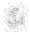
次に上述した処理炉202を図1を用いて具体的に説明する。なお、以下の説明では、処理炉202を、バッチ式のプラズマプロセスを用いて複数のウエハを一括してプラズマで処理する縦型処理炉に適用した場合を代表として説明する。
Next, the
処理炉202は、加熱手段としてのヒータ304と、処理容器としての反応管203とを備える。
The
反応管203の外周に上記したヒータ304が設けられており、ウエハ200を加熱するように構成されている。
The above-described
《処理容器》
ヒータ304の内部に上記した反応管203が設けられており、反応管203はウエハ200をプラズマ処理するように構成されている。反応管203は略円筒形をしており、内部に複数のウエハ200を一括処理する処理室201が形成されている。反応管203の上部は閉じ下部には開口部220が設けられており、開口部220はウエハ200を保持する基板保持具としてのボート217を処理室201内に挿入したり、処理室201内から抜き出したりするように構成されている。反応管203及びボート217は例えば石英などの誘電体で成形されている。
<Processing container>
The above-described
反応管203にはガス供給手段としてのガス導入ポート320が設けられ、ガス導入ポート320は処理室201内に処理ガスを供給するように構成されている。このガス導入ポート320には、処理室201内に処理ガスを均等に導入できるように、さらにその下流にノズルを立ち上げるようにしてもよい。
The
また、反応管203には排気手段が設けられ、排気手段は処理室201を排気するように構成されている。すなわち、排気手段は反応管203に接続された排気管317と、排気管317に設けられた圧力調整バルブ318と、圧力調整バルブ318の下流側の排気管317に設けられた真空ポンプ319とを備えており、真空ポンプ319は排気管317を介して処理室201内の雰囲気を排気するように構成されている。
Further, the
図示例では処理室201内にボート217が挿入されており、ボート217は複数のウエハ200を積層保持するように多段に構成されている。すなわち、上記したボート217には一対となる第1電極及び第2電極としての第1サセプタ電極305及び第2サセプタ電極306が交互に多段に重なるように積層されており、第1、第2サセプタ電極305、306間にプラズマを生成するように構成されている。図示例では、第1サセプタ電極305が4枚、第2サセプタ電極306が3枚で、合計7枚の電極が積層されている。
ウエハ200は、対向する第1、第2サセプタ電極305、306間に保持される。図示例では、第1、第2サセプタ電極305、306上にウエハ200を直接保持している。しかし、第1、第2サセプタ電極305、306の間にウエハ200を浮かして保持するようにしてもよい。
第1、第2サセプタ電極305、306は導電性材料を含む部材で形成されている。
In the illustrated example,
The
The first and second
ボート217の下部には回転板としてのキャップ受309が設けられており、キャップ受309はボート217を支持するように構成されている。このキャップ受309には後述する回転軸310を介して、開口部220を塞ぐ蓋体としてのシールキャップ219が設けられており、ボート217が処理室201内に挿入されたときに、シールキャップ219は処理室201を気密に閉塞するように構成されている。
なお、シールキャップ219やキャップ受309、回転軸366はステンレスやハステロイなどの金属製部材で形成され、一般的には接地される。
A
The
ボート217には回転機構はボート217を回転させる回転機構が設けられている。回転機構は、回転軸310、シール手段311、動力伝達手段312、回転駆動手段313とを備えており、回転駆動手段313の回転力を動力伝達手段312により回転軸310に与え、シール手段311で気密を保持しつつ回転軸310を回転させてボート217を回転するように構成されている。
The
すなわち、回転軸310は、ボート217を支持するキャップ受309の下面に鉛直方向に連結されている。回転軸310は内部が中空の円筒形をしており、キャップ受309と連結された回転軸310の上部はキャップ受309に設けた開口と連通してキャップ上部に開放されている。回転軸310の下部はシールキャップ219を貫通して大気に開放されている。
回転軸310はシールキャップ219の貫通部で軸支されている。軸支部にはシール手段311、例えば磁気シールが設けられており、回転軸310の貫通部を真空シールして、シールキャップ219により閉塞されている処理室201内の気密を保持するように構成されている。
動力伝達手段312は回転軸310の下部に取り付けられ、回転駆動手段313から回転軸310に与えられる回転力を制御して、ボート217の回転を制御するように構成されている。動力伝達手段312は、例えばギアまたはプーリ/ベルトから構成され、回転駆動手段313は例えばモータから構成される。
このようにして回転機構は、処理室201内の気密を保持しつつボート217を処理室内で回転自在に支持するように構成されている。
That is, the
The
The power transmission means 312 is attached to the lower part of the
In this way, the rotation mechanism is configured to rotatably support the
前記回転軸310の内部には第1及び第2電力供給ライン371、372が通り、回転軸310の上部から導出された第1及び第2電力供給ライン371、372は、ボート217上の第1、第2サセプタ電極305、306に電気的に接続されている。また、回転軸310の下部から導出された前記第1及び第2電力供給ライン371、372にそれぞれ第1回転コンデンサ314a及び第2回転コンデンサ314bが連結されており、第1回転コンデンサ314a及び第2回転コンデンサ314bは、ボート217が回転しても容量結合によって第1、第2サセプタ電極305、306に高周波電力をそれぞれ供給できるように構成されている。
The first and second
上記第1及び第2電力供給ライン371、372は、実施の形態によっては、円筒形の回転軸310内に挿通された回転軸331、332であることもある。図1に示す実施の形態では、回転軸310の内部に第1及び第2電力供給ライン371、372としての第1、第2回転軸331、332が挿通されており、第1、第2回転軸331、332は回転軸310内に同軸的に、かつ回転軸310及び第1、第2回転軸331、332が相互
に電気的な絶縁を保持されて、中空回転軸310と一体に回転するように構成されている。
The first and second
すなわち、第1回転軸331は導電性材料で形成され、回転軸310内の中心に挿通されて、第1回転軸上部が第1RFフィーダ307を介して第1サセプタ電極305に接続され、第1回転軸下部が第1回転コンデンサ314aに接続されて、ボート217を回転させた状態でも、容量結合によってRF電力を第1回転コンデンサ314aを介して第1回転軸331から第1サセプタ電極305に供給することができるように構成されている。
That is, the first
また、第2回転軸332は中空で導電性材料で形成され、第1回転軸331を同心状に囲むように筒状の回転軸310内に挿通されて、第2回転軸上部が第2RFフィーダ308を介して第2サセプタ電極306に接続され、第2回転軸下部が第2回転コンデンサ314bに接続されて、ボート217を回転させた状態でも、容量結合によって、第1サセプタ電極305とは位相の異なるRF電力を第2回転コンデンサ314bを介して第2回転軸332から第2サセプタ電極306に供給することができるように構成されている。
The second
さらに、第1回転軸331と第2回転軸332との間、及び第2回転軸332と中空回転軸310との間には絶縁体が設けられ、これらの絶縁体は、第1、第2回転軸331、332、及び中空回転軸310を相互に絶縁するように構成されている。これらの絶縁体は、中空回転軸310と同軸的に配設された筒状の絶縁スリーブ333、334を構成している。したがって、中空回転軸310の内側に中心側から第1回転軸331、絶縁スリーブ333、第2回転軸332、絶縁スリーブ334が同軸的に配設されることになる。
Furthermore, an insulator is provided between the first
前記第1回転コンデンサ314a及び第2回転コンデンサ314bに高周波電力供給手段が接続されており、高周波電力供給手段は第1及び第2サセプタ電極305、306に異なる位相の高周波電力を別々に供給するように構成されている。すなわち、高周波電力供給手段は、発振器315と、発振器315の非接地側に接続された整合器316と、整合器316と発振器315の接地側との間に一次側が接続され二次側がともに非接地の絶縁トランス330とを備えており、絶縁トランス330は二次側出力をともに接地から浮かすことにより、発振器315の出力する高周波電力を、例えば交互に180度位相が異なるように、第1、第2回転コンデンサ314a、314bを経由して第1、第2サセプタ電極305、306に印加できるように構成されている。
A high frequency power supply means is connected to the first
これにより、ボート217が回転した状態でも第1、第2回転コンデンサ314a、314bを経由して第1、第2サセプタ電極305、306にRF電力を供給することができるようになっている。
As a result, even when the
なお、第1、第2回転コンデンサ314a、314bの本体は固定する必要があるが、好ましくはシールキャップ219に取り付けて固定するようにするとよい。
The main bodies of the first and second
また、回転コンデンサは、できるだけ大きな静電容量を確保するため、その対向電極の比誘電率及び面積がともに大きく、対向電極間のギャップが小さくなるように、その形状を工夫して設計することが好ましい。例えば、図示例のように、シールキャップ219に取り付ける一方の電極と、これと対向するよう回転軸に取り付ける他方の電極とをかみ合わせて配置するようにした櫛形電極としたり、あるいは図示しないが対向する2つの電極のうちのシールキャップ219側に取り付ける一方の電極の面積を、回転軸側に取り付ける他方の電極よりも大きくし、その一方の電極の端部を折り曲げて、他方の電極をすっぽり覆うようにした袋状電極としたりするとよい。
In addition, in order to secure the largest possible capacitance, the rotating capacitor can be designed with a particular shape so that the relative permittivity and area of the counter electrode are both large and the gap between the counter electrodes is small. preferable. For example, as in the illustrated example, one electrode attached to the
このように図示例の実施の形態では、第1回転軸331及び第2回転軸332を介して第1サセプタ電極305及び第2サセプタ電極306間に位相の異なる高周波電力を供給するように構成されている。
As described above, the illustrated embodiment is configured to supply high-frequency power having different phases between the
なお、後述する各工程におけるヒータ304、圧力調整バルブ318、回転手段313、発振器315、ガス導入ポート320に設けたバルブ(図示せず)等の各部の制御は制御手段としのコントローラ300により行う。
It should be noted that control of each part such as a
次に、上述の縦型処理炉を使用して、半導体装置の製造工程の一工程として、ウエハ200にプラズマ処理を施す方法について説明する。
Next, a method of performing plasma processing on the
処理室201が大気圧の状態で、ボートエレベータ115(図2参照)によりシールキャップ219を下降してボート217を処理室201からアンロードする。このとき、ヒータ304の温度を下げて行うが、下げ過ぎてしまうと、ウエハ200のロード終了後、処理室201内部で温度を所定の値まで上昇させて安定させるのに相当の時間がかかってしまうため、通常はウエハ200の移送に支障が無い温度まで下げて、その温度に保持した状態で移送を行う。
With the
ボート217とウエハ移載機構125(図2、図3参照)との相互動作により複数枚(1バッチ分)のウエハ200を第1サセプタ電極305及び第2サセプタ電極306上に移載する。ウエハ移載後、シールキャップ219を上昇させて処理室201内部にボート217をロードし、シールキャップ219により処理室201内を密閉する。
A plurality (one batch) of
次に、真空ポンプ319により処理室201内を真空引きし、コントローラ300により処理室201の圧力が大気圧よりも低い所定の処理圧力となるよう制御する。また、回転機構によりボート217が所定の回転速度で回転するようにする。
Next, the inside of the
また、ヒータ304に電力を投入して反応管203内のボート217、第1、第2サセプタ電極305、306等、処理室201内部の部材を加熱して、ウエハ200を所定の処理温度となるよう制御する。
Further, power is supplied to the
同時に処理室201内部のガスを排気管317を通して真空ポンプ319により排気する。ウエハ200が所定の温度になった時点で減圧下の処理室201にガス導入ポート320から処理ガスを導入しつつ排気する。このとき圧力調整バルブ318によって処理室201内の圧力を一定の値に保持する。
At the same time, the gas inside the
処理室201内部が所定の圧力になったら、回転手段313をコントローラ300により回転制御してボート217を回転させる。そして、ボート217を回転しつつ、発振器315の出力する高周波電力を絶縁トランス330から、第1、第2回転コンデンサ314a、314b、及び第1、第2RFフィーダ307、308を介してサセプタ電極305、306に供給して、サセプタ電極305、306間にプラズマを生成する。第1、第2RFフィーダ307、308に供給する高周波電力の周波数は13.56MHzや400KHz程度のものが利用される。
When the inside of the
なお、サセプタ電極305、306の数は、プラズマ生成の条件等で決まるサセプタ電極305、306間の間隔と、処理室201の高さ方向の大きさの制約で決定される。
Note that the number of the
第1、第2サセプタ電極305、306間に生成されたプラズマにより処理ガスから反応種が生成され、この反応種によりウエハ200に成膜処理が施される。
処理温度としては、例えば、プラズマ処理が成膜処理である場合、クリーンルームの室
温(例えば20℃)〜850℃、処理圧力としては1〜1000Paが例示される。
Reactive species are generated from the processing gas by the plasma generated between the first and second
As the processing temperature, for example, when the plasma processing is a film forming process, the room temperature (for example, 20 ° C.) to 850 ° C. of the clean room is exemplified, and the processing pressure is 1-1000 Pa.
ウエハ200のプラズマ処理が終了すると、真空引き、不活性ガスによるパージ等により処理室201内の残留ガスを除去し、処理室201内温度を所定の温度まで降温した後、ボート217を処理室201からアンロードし、ボート217に保持された全てのウエハ200が冷えるまで、ボート217を所定位置で待機させる。待機させたボート217に保持されたウエハ200が所定温度まで冷却されると、ウエハ移載機構125等によりウエハを回収する。
When the plasma processing of the
本実施の形態によれば、ボート217を回転手段313によって回転させながらプラズマ処理する場合でも、発振器315の出力する交流電力を整合器316及び絶縁トランス330を介し、さらに第1、第2回転コンデンサ314a、314b経由して回転中のボート217に設置した複数のサセプタ電極に供給することができる。したがって、ウエハ200のプラズマ処理の面内均一性、さらには面間均一を一層向上することができる。
According to the present embodiment, even when plasma processing is performed while the
また、第1及び第2回転コンデンサ314a、314bを経由して異なる位相の高周波電力を別々に第1及び第2サセプタ電極305、306に供給するようにしたので、第1及び第2サセプタ電極305、306間に大きな電圧を加えることが可能となり、第1及び第2サセプタ電極305、306間で容易にプラズマ放電させることができる。したがって、ウエハ200のプラズマ処理の面内均一性を向上することができ、さらに面間均一性も向上することができる。特に、180度位相が異なるように第1、第2サセプタ電極305、306に高周波電力を印加すると、より容易にプラズマ放電させることができ、ウエハ200のプラズマ処理の面内均一性、さらには面間均一を一層向上することができる。
In addition, since high-frequency power having different phases is separately supplied to the first and second
また、本実施の形態によれば、第1、第2回転軸331、332は中空回転軸310と絶縁されているので、第1、第2サセプタ電極305、306に加えられるべき電界の一部が、中空回転軸310からシールキャップ219を介して筐体111(図2、図3参照)に向かって第1、第2サセプタ電極305、306間以外にプラズマが広がることがなくなるので、第1、第2サセプタ電極305、306間のプラズマ密度の低下を抑えることができる。したがって、ウエハ200のプラズマ処理の面内均一性、さらには面間均一性を向上することができる。
Further, according to the present embodiment, since the first and second
また、第1、第2回転軸331、332は中空回転軸310と同軸的に設けるのが好ましい。第1、第2回転軸331、332を中空回転軸310と同軸的に設けることで、第1、第2回転コンデンサ314a、314bの回転軸の軸心を第1、第2回転軸331、332と一致させることができるようになり、第1、第2回転コンデンサ314a、314bの取り付けが容易になる。
The first and second
なお、上記実施の形態は、バッチ式の装置についてであったが、本発明は枚葉式の装置にも適用可能である。
また、本発明は、シリコンウエハなどの基板の表面をプラズマを用いてエッチンクしたり、薄膜を形成したり、表面を改質したりする処理装置に適用可能である。
Although the above embodiment is for a batch type apparatus, the present invention is also applicable to a single wafer type apparatus.
The present invention can also be applied to a processing apparatus that etches the surface of a substrate such as a silicon wafer using plasma, forms a thin film, or modifies the surface.
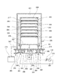
(比較例)
次に比較例を説明する。
(Comparative example)
Next, a comparative example will be described.
比較例では、回転軸の内部に2本の供給ラインを通し、一方の供給ラインを接地して第1電極に接続し、非接地の他方の供給ラインを回転可能な回転コンデンサを介して第2電極に接続した。2つの電極間に1つの回転コンデンサを介して高周波電力を供給すること
により被処理基板を回転しながらプラズマ処理できるようにした。
In the comparative example, two supply lines are passed through the rotary shaft, one supply line is grounded and connected to the first electrode, and the other non-grounded supply line is connected to the second via a rotatable capacitor. Connected to the electrode. By supplying high-frequency power between the two electrodes via a single rotating capacitor, plasma processing can be performed while rotating the substrate to be processed.
次に、比較例について図面を参照してより詳細に説明する。
図4は、比較例の縦型処理炉を示す構成図である。縦型処理炉の基本的構成要素は図1に関連して記述した実施例の縦型処理炉の対応する構成要素と同じであり、従ってここでは同一符号を付して説明を省略する。
Next, a comparative example will be described in more detail with reference to the drawings.
FIG. 4 is a configuration diagram showing a vertical processing furnace of a comparative example. The basic components of the vertical processing furnace are the same as the corresponding components of the vertical processing furnace of the embodiment described with reference to FIG.
比較例では、ガス導入ポート320の下流にノズル322を設け、このノズル322は処理室201内部に反応管203の側面に沿って垂直方向に設けるようにする。ノズル322には複数のガス供給用細孔321が設けられ、複数のガス供給用細孔321は、処理ガスを高さ方向に均等に供給するように大きさが調整されて、処理室201内に均等に処理ガスを導入できるように構成されている。
In the comparative example, a
また、比較例では、ウエハ200は電極305、306間の中間に配置されるように構成されている。すなわち、電極上にではなくボート217に多段に設けた係止溝にウエハ200を係止するようになっている。
In the comparative example, the
さらに、比較例では、シールキャップ219にシール手段311を介して貫通させた回転軸310の内部に第1、第2供給ライン307、308を通している。
Further, in the comparative example, the first and
第1供給ライン307により、第1電極305は、回転コンデンサ314を経由し、整合器316を介して発振器315に接続されており、第2電極306は発振器315の接地側である第2供給ライン(接地ライン)308に接続されており、発振器315の出力する高周波電力を整合器316を介して第1、第2電極305、306間に印加できるようになっている。
By the
このような構成においては、回転コンデンサ314aが設けられていない側の発振器315の接地側が、回転軸310から接地(アース)の経路で電気的に接続されることになるので、発振器315の非接地側の第1電極305からの電界が接地(アース)に向かい、プラズマが第1、第2電極305、306間以外に広がって、プラズマ密度が低下することが避けられない。したがって、この状態でプラズマを生成して処理すると、処理状態が不均一となる。
In such a configuration, the ground side of the
また、第2電極306が接地された第2供給ライン308に接続されているので、第1電極305に加えられている高周波電力が、同じく接地されている回転軸310の周囲のシールキャップ等へ逃げてしまうのが避けられず、プラズマ密度が低下してしまう。この状態でプラズマを生成して処理すると、処理状態が不均一となる。したがって、ウエハ200のプラズマ処理の面内均一性が実施例よりも劣る。
Further, since the
以下に本発明の好ましい形態を付記する。
減圧下の処理室の中に多段に被処理基板を重ねて載置しプラズマを用いて一括処理する装置において、ボートを回転させるためにシールキャップに設けた中空の回転軸の内側に2系統のRF導入ポートを同軸に設け、それぞれのRF導入ポートに回転可能に設けた回転コンデンサを介してRF電力を導入可能とすることで、被処理基板の均一性を確保できるために、プラズマ生成時もボートを回転できる。
The preferred embodiments of the present invention will be described below.
In an apparatus for stacking substrates to be processed in multiple stages in a processing chamber under reduced pressure and performing batch processing using plasma, two systems are provided inside a hollow rotating shaft provided in a seal cap for rotating a boat. The RF introduction port is provided coaxially, and RF power can be introduced via a rotating capacitor rotatably provided at each RF introduction port, so that the uniformity of the substrate to be processed can be secured. You can rotate the boat.
さらに第1電極と第2電極とが板状のサセプタ電極であり、サセプタ電極の上に被処理基板を保持するようにすると、基板を保持する基板保持体を電極とは別個に設ける場合に比べて構造を簡易化できる。 Furthermore, when the first electrode and the second electrode are plate-shaped susceptor electrodes and the substrate to be processed is held on the susceptor electrode, a substrate holding body for holding the substrate is provided separately from the electrodes. To simplify the structure.
好ましくは、第1系統のRF導入ポートは中空回転軸内の中心を通り、第2系統の導入ポートは第1系統RF導入ポートを同心状に囲むように中空回転軸内を通り、第1、第2RF導入ポートとの間、及び第2RF導入ポートと中空回転軸との間が絶縁体で絶縁されるようにする。異なる位相の高周波電力を第1電極、第2電極に別々に導入することができるので、位相に応じた高い印加電圧を加えることが可能になり、プラズマ放電を容易に起こすことができる。 Preferably, the first system RF introduction port passes through the center of the hollow rotation shaft, the second system introduction port passes through the hollow rotation shaft so as to concentrically surround the first system RF introduction port, and the first, Insulation is performed between the second RF introduction port and between the second RF introduction port and the hollow rotary shaft. Since high-frequency power having different phases can be separately introduced into the first electrode and the second electrode, a high applied voltage corresponding to the phase can be applied, and plasma discharge can be easily caused.
また好ましくは、前記第1回転コンデンサが、前記高周波電力供給手段の高周波電力を供給する一端と前記第1RF導入ポートとの間に回転可能に設けられ、前記第2回転コンデンサが、前記高周波電力供給手段の高周波電力を供給する他端と前記第2回高周波電力導入ポートとの間に回転可能に設けられ、前記高周波電力供給手段の一端と他端とから異なる位相の高周波電力を前記第1電極及び第2電極に別々に導入するようにする。異なる位相の高周波電力を第1電極、第2電極に別々に導入するので、位相に応じた高い印加電圧を加えることが可能になり、プラズマ放電を容易に起こすことができる。 Preferably, the first rotating capacitor is rotatably provided between one end of the high frequency power supply means for supplying high frequency power and the first RF introduction port, and the second rotating capacitor is provided with the high frequency power supply. A high-frequency power having a phase different from that of the one end and the other end of the high-frequency power supply means is provided between the other end of the high-frequency power supply means and the second high-frequency power introduction port. And separately introduced into the second electrode. Since high-frequency powers having different phases are separately introduced into the first electrode and the second electrode, a high applied voltage corresponding to the phase can be applied, and plasma discharge can be easily caused.
また好ましくは、前記高周波電力供給手段の高周波電力(を供給する端子)が絶縁トランスを介して第1回転コンデンサ、第2回転コンデンサに接続されるようにする。絶縁トランスを介して第1回転コンデンサ、第2回転コンデンサ高周波電力を導入するので、第1電極、第2電極を接地から浮かして、位相をずらすことによって、より高い印加電圧を第1電極、第2電極間に加えることが可能になり、プラズマ放電を一層容易に起こすことができる。 Preferably, the high-frequency power of the high-frequency power supply means is connected to the first rotating capacitor and the second rotating capacitor via an insulating transformer. Since the first rotating capacitor and the second rotating capacitor high-frequency power are introduced through the insulating transformer, the first electrode and the second electrode are floated from the ground, and the phase is shifted, so that a higher applied voltage can be applied to the first electrode and the second electrode. It becomes possible to apply between two electrodes, and plasma discharge can be caused more easily.
200 ウエハ(被処理基板)
201 処理室
203 反応管(処理容器)
217 ボート(基板保持具)
219 シールキャップ(蓋体)
220 開口部
305 第1サセプタ電極
306 第2サセプタ電極
310 回転軸
314a 第1回転コンデンサ
314b 第2回転コンデンサ
315 高周波発振器(電力供給手段)
317 排気管
320 ガス導入ポート(ガス供給手段)
329 真空ポンプ
331 第1回転軸
332 第2回転軸
333、334 絶縁スリーブ(絶縁体)
371 第1電力供給ライン
372 第2電力供給ライン
200 wafer (substrate to be processed)
201
217 boat (substrate holder)
219 Seal cap (lid)
220
317
329
371 First
Claims (2)
前記処理室内にガスを供給するガス供給手段と、
前記処理室内を排気する排気手段と、
前記開口部から前記処理室内に挿入され被処理基板を保持する基板保持具と、
前記基板保持具に積層されるプラズマ生成用の少なくとも1対の電極であって、該電極間に前記被処理基板が配置される第1電極及び第2電極と、
前記基板保持具を前記処理室内で回転自在に支持するための回転軸と、
前記回転軸を回転自在に軸支し前記開口部を閉塞する蓋体と、
前記回転軸の中を通って前記処理室の内部に導入され前記第1電極と前記第2電極とにそれぞれ電気的に接続される第1電力供給ライン及び第2電力供給ラインと、
前記回転軸の中を通って前記処理室の外部に導出される前記第1電力供給ライン及び第2電力供給ラインにそれぞれ接続される第1回転コンデンサ及び第2回転コンデンサと、
前記第1回転コンデンサ及び第2回転コンデンサを介して、前記第1電極及び第2電極に異なる位相の高周波電力を別々に供給する高周波電力供給手段と、
を備えた基板処理装置。 A processing container having an opening and forming a processing chamber therein;
Gas supply means for supplying gas into the processing chamber;
Exhaust means for exhausting the processing chamber;
A substrate holder that is inserted into the processing chamber from the opening and holds a substrate to be processed;
At least one pair of electrodes for plasma generation laminated on the substrate holder, the first electrode and the second electrode on which the substrate to be processed is disposed between the electrodes;
A rotating shaft for rotatably supporting the substrate holder in the processing chamber;
A lid that pivotally supports the rotating shaft and closes the opening;
A first power supply line and a second power supply line that are introduced into the processing chamber through the rotating shaft and electrically connected to the first electrode and the second electrode, respectively.
A first rotating capacitor and a second rotating capacitor respectively connected to the first power supply line and the second power supply line led out of the processing chamber through the rotating shaft;
High-frequency power supply means for separately supplying high-frequency power of different phases to the first electrode and the second electrode via the first rotating capacitor and the second rotating capacitor;
A substrate processing apparatus comprising:
前記処理室内にガスを供給するガス供給手段と、
前記処理室内を排気する排気手段と、
前記開口部から前記処理室内に挿入され被処理基板を保持する基板保持具と、
前記基板保持具に積層されるプラズマ生成用の少なくとも1対の電極であって、該電極間に前記被処理基板が配置される第1電極及び第2電極と、
前記基板保持具を前記処理室内で回転自在に支持するための筒状の回転軸と、
前記筒状の回転軸を回転自在に軸支し前記開口部を閉塞する蓋体と、
前記筒状の回転軸内の中心に挿通されて前記処理室の内部で前記第1電極に電気的に接続される導電性の第1回転軸と、
前記第1回転軸を同心状に囲むように前記筒状の回転軸内に挿通されて前記第2電極に電気的に接続される導電性で中空の第2回転軸と、
前記第1回転軸と第2回転軸との間、及び第2回転軸と前記筒状の回転軸との間を絶縁する絶縁体と、
前記第1回転軸及び前記第2回転軸を介して第1電極及び前記第2電極間に異なる位相の高周波電力を別々に供給する高周波電力供給手段と、
を備えた基板処理装置。
A processing container having an opening and forming a processing chamber therein;
Gas supply means for supplying gas into the processing chamber;
Exhaust means for exhausting the processing chamber;
A substrate holder that is inserted into the processing chamber from the opening and holds a substrate to be processed;
At least one pair of electrodes for plasma generation laminated on the substrate holder, the first electrode and the second electrode on which the substrate to be processed is disposed between the electrodes;
A cylindrical rotating shaft for rotatably supporting the substrate holder in the processing chamber;
A lid that rotatably supports the cylindrical rotation shaft and closes the opening;
A conductive first rotating shaft that is inserted into the center of the cylindrical rotating shaft and is electrically connected to the first electrode inside the processing chamber;
A conductive and hollow second rotating shaft that is inserted into the cylindrical rotating shaft so as to concentrically surround the first rotating shaft and is electrically connected to the second electrode;
An insulator for insulating between the first rotating shaft and the second rotating shaft and between the second rotating shaft and the cylindrical rotating shaft;
High-frequency power supply means for separately supplying high-frequency power of different phases between the first electrode and the second electrode via the first rotating shaft and the second rotating shaft;
A substrate processing apparatus comprising:
Priority Applications (1)
| Application Number | Priority Date | Filing Date | Title |
|---|---|---|---|
| JP2007110513A JP4833143B2 (en) | 2007-04-19 | 2007-04-19 | Substrate processing equipment |
Applications Claiming Priority (1)
| Application Number | Priority Date | Filing Date | Title |
|---|---|---|---|
| JP2007110513A JP4833143B2 (en) | 2007-04-19 | 2007-04-19 | Substrate processing equipment |
Publications (2)
| Publication Number | Publication Date |
|---|---|
| JP2008270477A JP2008270477A (en) | 2008-11-06 |
| JP4833143B2 true JP4833143B2 (en) | 2011-12-07 |
Family
ID=40049600
Family Applications (1)
| Application Number | Title | Priority Date | Filing Date |
|---|---|---|---|
| JP2007110513A Active JP4833143B2 (en) | 2007-04-19 | 2007-04-19 | Substrate processing equipment |
Country Status (1)
| Country | Link |
|---|---|
| JP (1) | JP4833143B2 (en) |
Families Citing this family (4)
| Publication number | Priority date | Publication date | Assignee | Title |
|---|---|---|---|---|
| US9853579B2 (en) * | 2013-12-18 | 2017-12-26 | Applied Materials, Inc. | Rotatable heated electrostatic chuck |
| CN105990082A (en) * | 2015-02-15 | 2016-10-05 | 盛美半导体设备(上海)有限公司 | Semiconductor etching device |
| TWI798760B (en) | 2020-08-26 | 2023-04-11 | 日商國際電氣股份有限公司 | Substrate processing apparatus, manufacturing method of semiconductor device, substrate holder and program |
| CN215925072U (en) * | 2020-09-24 | 2022-03-01 | 株式会社国际电气 | Substrate processing apparatus |
Family Cites Families (4)
| Publication number | Priority date | Publication date | Assignee | Title |
|---|---|---|---|---|
| JPS61136221A (en) * | 1984-12-07 | 1986-06-24 | Asaka Giken :Kk | Apparatus for forming gaseous phase plasma chemical reaction |
| ATE75346T1 (en) * | 1988-11-07 | 1992-05-15 | Balzers Hochvakuum | PERFORMANCE FOR APPLYING RF ENERGY AND THEIR USE. |
| JP2001181831A (en) * | 1999-12-27 | 2001-07-03 | Shin Meiwa Ind Co Ltd | Ion machining apparatus, and electricity supply structure for ion machining |
| JP2006278652A (en) * | 2005-03-29 | 2006-10-12 | Hitachi Kokusai Electric Inc | Board processor |
-
2007
- 2007-04-19 JP JP2007110513A patent/JP4833143B2/en active Active
Also Published As
| Publication number | Publication date |
|---|---|
| JP2008270477A (en) | 2008-11-06 |
Similar Documents
| Publication | Publication Date | Title |
|---|---|---|
| KR101334758B1 (en) | Substrate processing apparatus and method of manufacturing semiconductor device | |
| KR100662959B1 (en) | Plasma processing machine and method thereof | |
| KR101040992B1 (en) | Substrate processing apparatus | |
| US11101111B2 (en) | Substrate processing apparatus, method of manufacturing semiconductor device, and baffle structure of the substrate processing apparatus | |
| TW202111851A (en) | Transfer method and transfer apparatus for substrate processing system | |
| WO2006118161A1 (en) | Substrate treating apparatus and electrode | |
| US20090093124A1 (en) | Method of manufacturing semiconductor device | |
| KR20140016421A (en) | Apparatus, system and method for treating substrate | |
| JP4833143B2 (en) | Substrate processing equipment | |
| JP2008300444A (en) | Semiconductor manufacturing apparatus | |
| KR20200022681A (en) | Buffer unit, Apparatus and Method for treating substrate with the unit | |
| JP2009059900A (en) | Substrate treating device | |
| TW200929416A (en) | Substrate-receiving device and substrate-receiving method | |
| TWI808675B (en) | Plasma treatment device and plasma treatment method | |
| JP2008311555A (en) | Substrate treatment device | |
| KR101372333B1 (en) | Substrate processing module and substrate processing apparatus including the same | |
| JP2006278652A (en) | Board processor | |
| CN113725125A (en) | Single-chip radio frequency plasma glue sweeping equipment | |
| JP5825948B2 (en) | Substrate processing apparatus and semiconductor device manufacturing method | |
| JPH06349931A (en) | Processing system | |
| JP7121786B2 (en) | Substrate processing apparatus, semiconductor device manufacturing method, and substrate processing method | |
| JP2009130225A (en) | Substrate processing apparatus | |
| JP4895685B2 (en) | Substrate processing apparatus and semiconductor device manufacturing method | |
| JP2009212322A (en) | Substrate processing apparatus | |
| JP2007059527A (en) | Substrate treatment device |
Legal Events
| Date | Code | Title | Description |
|---|---|---|---|
| A621 | Written request for application examination |
Free format text: JAPANESE INTERMEDIATE CODE: A621 Effective date: 20100330 |
|
| TRDD | Decision of grant or rejection written | ||
| A01 | Written decision to grant a patent or to grant a registration (utility model) |
Free format text: JAPANESE INTERMEDIATE CODE: A01 Effective date: 20110907 |
|
| A977 | Report on retrieval |
Free format text: JAPANESE INTERMEDIATE CODE: A971007 Effective date: 20110908 |
|
| A01 | Written decision to grant a patent or to grant a registration (utility model) |
Free format text: JAPANESE INTERMEDIATE CODE: A01 |
|
| A61 | First payment of annual fees (during grant procedure) |
Free format text: JAPANESE INTERMEDIATE CODE: A61 Effective date: 20110921 |
|
| R150 | Certificate of patent or registration of utility model |
Ref document number: 4833143 Country of ref document: JP Free format text: JAPANESE INTERMEDIATE CODE: R150 Free format text: JAPANESE INTERMEDIATE CODE: R150 |
|
| FPAY | Renewal fee payment (event date is renewal date of database) |
Free format text: PAYMENT UNTIL: 20140930 Year of fee payment: 3 |
|
| R250 | Receipt of annual fees |
Free format text: JAPANESE INTERMEDIATE CODE: R250 |
|
| S111 | Request for change of ownership or part of ownership |
Free format text: JAPANESE INTERMEDIATE CODE: R313111 |
|
| S531 | Written request for registration of change of domicile |
Free format text: JAPANESE INTERMEDIATE CODE: R313531 |
|
| R350 | Written notification of registration of transfer |
Free format text: JAPANESE INTERMEDIATE CODE: R350 |