JP4828689B2 - Illumination optics - Google Patents
Illumination optics Download PDFInfo
- Publication number
- JP4828689B2 JP4828689B2 JP2000278026A JP2000278026A JP4828689B2 JP 4828689 B2 JP4828689 B2 JP 4828689B2 JP 2000278026 A JP2000278026 A JP 2000278026A JP 2000278026 A JP2000278026 A JP 2000278026A JP 4828689 B2 JP4828689 B2 JP 4828689B2
- Authority
- JP
- Japan
- Prior art keywords
- light
- illumination
- lens
- lens system
- optical system
- Prior art date
- Legal status (The legal status is an assumption and is not a legal conclusion. Google has not performed a legal analysis and makes no representation as to the accuracy of the status listed.)
- Expired - Fee Related
Links
Images


Description
【0001】
【発明の属する技術分野】
本発明は、光源よりの光を輪帯状に反射する部材を有する照明光学系で、輪帯状光束を使用する場合と均一照明として使用する場合に対応でき、両者を切り換え可能にした照明光学系に関するものである。
【0002】
【従来の技術】
光源からの照明光を効率よく利用するためランプと反射部材とを組み合わせた照明光学系は、従来より数多く知られている。このような照明光学系のように、ランプと反射部材とを組み合わせた光学系は、ランプ自体が影になるために中心部分が中抜けになり、均一な照明ができない。
【0003】
特開平9−152553号公報に記載されている光学系は、ランプよりの光を反射部材により集光させた光を錐体状光屈折素子にて光の方位角を変えその後ホログラム拡散素子により拡散させ、最終的に均一化を図ろうとした光学系である。
【0004】
また、特開平6−216008号公報に記載された光学系は、フライアイレンズにより光源の像を多数形成することにより、見掛け上大きな2次光源とし、これをステッパー用投影レンズの瞳位置に投影することによって、ケーラー照明を行ない、均一な照明を行なうようにしたものである。
【0005】
【発明が解決しようとする課題】
顕微鏡照明等においては、複数の検鏡を切り換え行なうことがある。例えば均一な照明が求められる明視野観察と、輪帯状光束により観察光学系の開口数より大きな角度により照明して観察を行なう暗視野観察とを切り換え行なわれる。
【0006】
即ち、明視野観察の場合、光源よりの光をコンデンサーレンズ等の前側焦点位置(瞳位置)に投影してケーラー照明を行なう。また、一層均一な照明を行なうために、光路中に光拡散手段やフライアイレンズ等を配置することが多い。一方暗視野観察の場合、例えば図10に示すような暗視野対物レンズを用いて光源からの光を輪帯状の平行光とし、これを対物レンズのレンズと外枠との間から導入して対物レンズの先端付近で、ミラー等によって物体面に集光するクリティカル照明が行なわれる。
【0007】
前記従来例の特開平9−152553号公報に記載されている照明光学系を顕微鏡照明に適用する場合、ターゲット位置と顕微鏡コンデンサーレンズの瞳位置とを合わせれば、明視野のケーラー照明を実現することができる。しかし、この従来例は、輪帯照明を行ない得るものではなく、またクリティカル照明を行なえるものではなく、そのため複数の検鏡に対応し得る照明光学系を構成できない。
【0008】
また、前記従来例のうち、特開平6−216008号公報に開示されている照明光学系を顕微鏡照明に適用する場合、そのままで明視野のケーラー照明を実現できる。しかし、輪帯状照明として使用し得る手段を有しておらず、またクリティカル照明にするための手段も示されておらず、したがって複数の検鏡に対応する照明光学系になし得ない。
【0009】
本発明は、ケーラー照明やクリティカル照明等の様々な観察法においても最適な状態にて照明し得るように容易に切り換え得る照明光学系を提供するものである。
【0010】
【課題を解決するための手段】
本発明の照明光学系は、光源と物体面との間に配置されていて、光源側より、コレクター光学系と、光路に対し挿脱可能なレンズ系と、正の焦点距離を有するレンズ系とを少なくとも含んでおり、前記コレクター光学系が、前記光源からの光を輪帯状に反射する反射手段を少なくとも含んでいて前記光源からの光を第1の集光位置に集光するものであり、前記正の焦点距離を有するレンズ系と前記光路に対し挿脱可能に配置されたレンズ系の各々の前側焦点位置が前記コレクター光学系による集光位置に略一致するように配置され、前記光路に挿脱可能なレンズ系を光路に挿入した時、光源よりの光が集光する第2の集光位置近傍に光拡散手段が配置され、前記光路に対し挿脱可能なレンズ系を光路から外した時には前記光拡散手段も光路から外されるように構成したことを特徴とする。
【0011】
即ち、本発明の照明光学系は、例えば図1に示し後に詳細に説明する第1の実施の形態の照明光学系のような構成のもので、光源1とコレクター光学系2と光路に対し挿脱可能なレンズ系(凹レンズ3)と、正の焦点距離のレンズ系(凸レンズ4)とよりなり、第2の集光位置6に光拡散手段5が配置されていて、図1(A)のように光路に対して挿脱可能なレンズ系(凹レンズ3)が光路中に挿入されている時は光拡散手段5も光路中に配置され、また図1(B)のように、光路に対して挿脱可能なレンズ系(凹レンズ3)が光路から外される時は光拡散手段5も光路から外される。
【0012】
このような照明光学系において、(B)に示すようにレンズ系3が光路から外されている場合、図示するようにコレクター光学系2によって第1の集光位置6に集光した光は、正の焦点距離を有するレンズ系4の前側焦点位置が前記の第1の集光位置に略一致しているので、略平行光束で射出する。光源からの光は、コレクター光学系の反射手段にて輪帯状に反射されるので、この略平行な光束も輪帯光束になる。そのため例えば図10に示すように暗視野対物に導くことにより暗視野照明にすることができる。
【0013】
また、図1(A)のようにコレクター光学系2と正の焦点距離を有するレンズ系4との間の光路中に光路に対し挿脱可能なレンズ系3を挿入した時は、この挿脱可能なレンズ系の前側焦点位置と第1の集光位置とが略等しいため、光路から挿脱可能なレンズ系を射出する光束が略平行な光束になり、その後この光束は正の焦点距離を有するレンズ系4により第2の集光位置に集光される。
【0014】
この第2の集光位置近傍には光拡散手段5が配置されているため、この光拡散手段5の拡散作用によりある角度範囲内に拡がる比較的均一な光束になる。
【0015】
この拡散手段より発する拡散光を2次光源とした照明系を構成することにより明視野照明を行なうことができる。
【0016】
以上のように、本発明の照明光学系は、光路に対し挿脱可能なレンズ系と光拡散手段とを光路に挿入することにより明視野照明となり、また光路より外すことにより暗視野照明となり、上記レンズ系と光拡散手段の挿脱によって明視野と暗視野の切り換えが可能である。
【0017】
また、本発明の照明光学系において、正の焦点距離を有するレンズ系を切り換え可能かまたは焦点距離可変な構成にしてもよい。
【0018】
暗視野観察においては、観察対物レンズが変わると観察に必要な開口数が変化し、これに応じて照明側の開口数を変化させる必要がある。また、顕微鏡位相差観察を行なう場合も輪帯照明が用いられる。この場合も観察対物が変わると照明系の開口数が変化するので、照明系の開口数を可変にする必要がある。そして照明系の開口数は、輪帯状光束の径を変化させることにより変化させ得る。また輪帯の径は、光束を略平行にするレンズの焦点距離が長くなると径は大きくなり、焦点距離が短くなると径は小さくなる。したがって、正の焦点距離を有するレンズ系が焦点距離の異なるものに切り換え可能であるかあるいは焦点距離が可変であるようにすることにより、輪帯の径を変化させえることができ、その結果、照明の開口数を変化させることができる。ここで、レンズ系の切り換えにより焦点距離を切り換える場合、レンズ系全体を切り換えてもまたレンズ系中の一部のレンズを切り換えてもよい。
【0019】
更に、本発明は、同一光路上で第1の照明形態と第2の照明形態のいずれか一方を形成する照明光学系であって、前記第1の照明形態と前記第2の照明形態は光路上に、光源と、前記光源からの光を輪帯状に反射する反射部材を少なくとも含み前記光源からの光を第1の集光位置に集光させるコレクタ−光学系と、正の焦点距離を有するレンズ系を備え、前記第1の照明形態は、前記正の焦点距離を有するレンズ系が前記第1の焦光位置に前側焦点位置が略一致するように配置され、前記第2の照明形態は、光拡散部材と、前記光源と前記正の焦点距離を有するレンズ系との間に配置される変換レンズ系とを備え、前記変換レンズ系は前記第1の集光位置に前側焦点位置が略一致するように配置され、前記光拡散部材が前記正の焦点位置を有するレンズ系と前記変換レンズ系によって光が集光する第2の集光位置に配置されている照明光学系である。
【0020】
【発明の実施の形態】
次に本発明の照明光学系の実施の形態について述べる。
【0021】
図1は、本発明の第1の実施の形態の照明光学系の構成を示すもので、この第1の実施の形態は、本発明の照明光学系の一例である。つまり図1に示すように、光源1と、コレクター光学系2と、光路に対し挿脱可能に構成されたレンズ系3と、正の焦点距離を有するレンズ系4とにて構成されている。また、コレクター光学系2は光源1からの光を輪帯状に反射する反射手段である楕円反射鏡2aを有し、このコレクター光学系2により光源1よりの光を第1の集光位置6に集光する。また正の焦点距離を有するレンズ系4と光路に対し挿脱可能なレンズ系3の前側焦点位置がコレクター光学系2による第1の集光位置に一致するように配置され、図1(A)に示すようにレンズ系4を光路中に挿入した時には、光源からの光を集光する第2の集光位置7に光拡散手段5が配置され、また図1(B)のようにレンズ系3が光路より外された時には光拡散手段5も光路から外されるように構成されている。
【0022】
このように、図1(A)においては光拡散手段5が配置されることにより、これより発する拡散光が2次光源となり通常の照明系を構成し、また図1(B)においては、レンズ系4を射出する光束が輪帯状の平行光束となり、輪帯状の照明が可能になる。
【0023】
このように第1の実施の形態によれば、凹レンズよりなるレンズ系3と光拡散手段5とを光路に対して挿脱することにより図1において(A)と(B)に示す照明を切り換え行なうことが可能である。つまり、例えば明視野照明と暗視野照明の両方を切り換えて行なうことが可能である。
【0024】
図2は本発明の照明光学系の第2の実施の形態を示すものである。
【0025】
この第2の実施の形態は、図2に示すように光路に対し挿脱可能であるレンズ系8として1枚の凸レンズを用いたもので、この1枚の凸レンズよりなるレンズ系8をその前側焦点位置がコレクター光学系2による第1の集光位置と略一致するように配置したもので、その他の点は第1の実施の形態と実質上同じである。
【0026】
この第2の実施の形態において、凸レンズよりなるレンズ系8と光拡散手段5とを光路より外すことによって、図1(B)に示す構成と同じになる。したがって、この第2の実施の形態の照明光学系において、レンズ系8と光拡散手段5とを光路に対して挿脱することにより図1の(A)、(B)と同様な切り換えが可能である。
【0027】
本発明の第3の実施の形態は、コレクター光学系として、放物面ミラーと凸レンズにて構成したもので、その他の構成は第1、第2の実施の形態の照明光学系と基本的に同じである。
【0028】
図3は前記の放物面鏡と凸レンズよりなるコレクター光学系のみを示す。図において、2bは放物ミラー、2cは凸レンズで、これらによりコレクター光学系2を構成し、このコレクター光学系2により光源1よりの光は第1の集光位置に集光される。そしてこの第1の集光位置に前側焦点位置が一致するように凸レンズよりなるレンズ系4が配置されており、第1の実施の形態における図1(B)と実質上同様の構成になる。これに図1(A)に示すレンズ系3と光拡散手段5あるいは図2に示すレンズ系8と光拡散手段5とが光路中に挿入されることにより図1(A)あるいは図2に示すものと実質上同じ構成になる。
【0029】
本発明の第4の実施の形態は、第1〜第3の実施の形態の照明光学系において、正の焦点距離を有するレンズ系を図4に示すようなズームレンズにしたものである。
【0030】
このズームレンズは、正レンズの第1群4aと負レンズの第2群4bと正レンズの第3群4cとよりなり、これらレンズ群4a、4b、4cを図示するように移動させてレンズ系4の焦点距離を変化させ得るようにした。このようにレンズ系の焦点距離を変化させて、レンズ系を射出する輪帯状光束の径を変化させることを可能にし、これにより観察光学系等に合わせて輪帯状光束の径を変え得るようにした。
【0031】
第5の実施の形態は、第1〜第3の実施の形態の照明光学系の正の焦点距離のレンズ系4を複数のレンズにて構成し、その一部のレンズを光路に対して挿脱可能にしたものである。つまりこの実施の形態の照明光学系の正の焦点距離のレンズ系は例えば図5に示すように正レンズ4dと正レンズ4eと負レンズ4fの3枚のレンズにて構成し、そのうちの正レンズ4eと負レンズ4fとを挿脱可能にしたものである。これによって、図5(A)に示すように正レンズ4eと負レンズ4fが光路外に外された時と、(B)に示すようにこれら正レンズ4e、負レンズ4fを光路中に挿入した時とでこのレンズ系を射出する光束の径が変化する。つまり正の焦点距離のレンズ系の一部のレンズである正レンズと負レンズを挿脱することにより、このレンズ系を射出する光束の径を切り換えることができる。
【0032】
次の本発明の照明光学系の参考例1は、図6に示すような構成の光学系で、光源1とコレクター光学系2と中間光学系10とコンデンサー光学系11より構成されている。ここでコレクター光学系2は第1の実施の形態等と同様の構成であり、このコレクター光学系2による第1の集光位置に前側焦点位置が略一致するように中間光学系が配置され第1の集光位置と物体面が共役になるように中間光学系10とコンデンサー光学系11とが配置され、これら中間光学系10、コンデンサー光学系11を通して物体面12を照明するように構成されている。これにより、輪帯状光束で、クリティカル照明を可能にしている。
【0033】
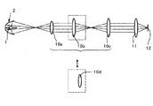
図7は本発明の参考例2を示すものである。この参考例2の照明光学系は、参考例1と実質上同じ構成の照明光学系で、中間光学系10を構成する三つの正のレンズ群10a、10b、10cのうちの2番目の正レンズ群10bを他の正レンズ群10dと交換し得る構成にした。これにより交換前の図6に示す時と交換後の図7に示す時とで中間光学系を射出する輪帯状の光束の径を切り換え得るようにしたのが参考例2である。
【0034】
この参考例2のように中間光学系10の第2のレンズ群10bの交換の代わりに中間光学系の第1のレンズ群10aをズームレンズにすることによっても中間光学系を射出する輪帯状の光束の径を変化させることが可能である。また上記の手段を組み合わせたものでもよい。同様に第3のレンズ群10cの交換によって輪帯光束の径を切り換えてもよい。
【0035】
本発明の参考例3は、光源と、コレクター光学系と、中間光学系と、コンデンサー光学系よりなる照明光学系で、図8に示すようにコレクター光学系2と中間光学系10の間にその前側焦点位置が第1の集光位置に一致するように凹レンズからなるレンズ系3を配置し、これにより光源1よりの光が第2の集光位置に集光するようにしたもので、この第2の集光位置に光拡散手段5を配置するようにしたものである。また、前記第2の集光位置は、コンデンサー光学系11の前側焦点位置と共役になり、それによってケーラー照明が行なえるようにしたものである。この第2の集光位置に配置された光拡散手段により拡散される光の拡散角度が前述の条件つまり下記条件を満足するようにして、中抜けが解消され、必要な照明範囲を均一な光にて照明し得るようにしたものである。
φ≧θ
【0036】
次に第6の実施形態は、前記の参考例3の照明光学系において、凹レンズよりなるレンズ系3と光拡散手段5とを光路に対して挿脱可能な構成にしたものである。つまり図9(A)に示すように凹レンズよりなるレンズ系3と光拡散手段5とを光路から外した状態と図9(B)に示すように前記レンズ系3と光拡散手段5とを光路中に挿入した状態とに切り換え可能にした。これにより(A)の均一なケーラー照明と(B)の輪帯状のクリティカル照明との切り換えが可能になる。
【0037】
本発明の照明光学系は以上述べたような構成のもので、特許請求の範囲に記載するもののほか下記の各項に記載する照明光学系も本発明の目的を達成し得る。
【0038】
(1) 特許請求の範囲の請求項1に記載されている照明光学系で、正の焦点距離を有するレンズ系が他のレンズ系と切り換え可能であるかあるいは焦点距離可変のレンズ系であることを特徴とする照明光学系。
【0039】
(2) 同一光路上で第1の照明形態と第2の照明形態のいずれか一方を形成する照明光学系であって、前記第1の照明形態と前記第2の照明形態は光路上に、光源と、前記光源からの光を輪帯状に反射する反射部材を少なくとも含み前記光源からの光を第1の集光位置に集光させるコレクター光学系と、正の焦点距離を有するレンズ系を備え、前記第1の照明形態は、前記正の焦点距離を有するレンズ系が前記第1の集光位置に前側焦点位置が略一致するように配置され、前記第2の照明形態は、光拡散部材と、前記光源と前記正の焦点距離を有するレンズ系との間に配置される変換レンズ系とを備え、前記変換レンズ系は前記第1の集光位置に前側焦点位置が略一致するように配置され、前記光拡散部材が前記正の焦点距離を有するレンズ系と前記変換レンズ系によって光が集光する第2の集光位置に配置されている照明光学系。
【0040】
【発明の効果】
本発明の照明光学系によれば、ケーラー照明やクリティカル照明等の様々な観察法において用いられる照明が切り換え行ない得、しかも最適な状態にて行ない得るもので、また切り換えが極めて容易である等の効果を有する。
【図面の簡単な説明】
【図1】 本発明の第1の実施の形態を示す図
【図2】 本発明の第2の実施の形態を示す図
【図3】 本発明の第3の実施の形態を示す図
【図4】 本発明の第4の実施の形態を示す図
【図5】 本発明の第5の実施の形態を示す図
【図6】 本発明の参考例1を示す図
【図7】 本発明の参考例2を示す図
【図8】 本発明の参考例3を示す図
【図9】 本発明の第6の実施の形態を示す図
【図10】 暗視野対物レンズの構成を示す図
【図11】 光拡散手段における拡散角度の説明図
【符号の説明】
1 光源
2 コレクター光学系
3 挿脱可能なレンズ系
4 正の焦点距離のレンズ系
5 光拡散手段
8 挿脱可能なレンズ系
10 中間光学系
11 コンデンサー光学系[0001]
BACKGROUND OF THE INVENTION
The present invention relates to an illumination optical system having a member that reflects light from a light source in a ring shape, and can be used for a case where a ring-shaped light beam is used and a case where it is used as uniform illumination. Is.
[0002]
[Prior art]
Many illumination optical systems that combine a lamp and a reflecting member in order to efficiently use illumination light from a light source have been known. Like such an illumination optical system, an optical system in which a lamp and a reflecting member are combined has a shadow at the center of the lamp itself, so that the central portion becomes hollow and uniform illumination cannot be performed.
[0003]
In the optical system described in Japanese Patent Laid-Open No. 9-152553, light obtained by condensing light from a lamp by a reflecting member is changed by a cone-shaped photorefractive element and then diffused by a hologram diffusing element. This is an optical system that finally attempts to make uniform.
[0004]
Further, the optical system described in Japanese Patent Laid-Open No. 6-216008 forms an apparently large secondary light source by forming a large number of light source images with a fly-eye lens, and projects this onto the pupil position of a stepper projection lens. By doing so, Koehler illumination is performed and uniform illumination is performed.
[0005]
[Problems to be solved by the invention]
In microscope illumination or the like, a plurality of speculums may be switched. For example, switching between bright field observation in which uniform illumination is required and dark field observation in which observation is performed by illuminating with an annular light beam at an angle larger than the numerical aperture of the observation optical system is performed.
[0006]
That is, in the case of bright field observation, Koehler illumination is performed by projecting light from a light source onto the front focal position (pupil position) of a condenser lens or the like. In order to perform more uniform illumination, a light diffusing means, a fly-eye lens, etc. are often arranged in the optical path. On the other hand, in the case of dark field observation, for example, using a dark field objective lens as shown in FIG. 10, the light from the light source is converted into a ring-shaped parallel light and introduced from between the lens of the objective lens and the outer frame. In the vicinity of the tip of the lens, critical illumination is performed by focusing on the object surface by a mirror or the like.
[0007]
When applying the illumination optical system described in Japanese Patent Laid-Open No. 9-152553 in the above-mentioned conventional example to microscope illumination, bright field Koehler illumination is realized by combining the target position and the pupil position of the microscope condenser lens. Can do. However, this conventional example is not capable of performing annular illumination, and is not capable of performing critical illumination. Therefore, an illumination optical system capable of supporting a plurality of speculums cannot be configured.
[0008]
In addition, among the conventional examples, when the illumination optical system disclosed in JP-A-6-216008 is applied to microscope illumination, bright field Koehler illumination can be realized as it is. However, there is no means that can be used as an annular illumination, and no means for making critical illumination is shown, and therefore an illumination optical system corresponding to a plurality of speculums cannot be realized.
[0009]
The present invention provides an illumination optical system that can be easily switched so that illumination can be performed in an optimum state even in various observation methods such as Kohler illumination and critical illumination.
[0010]
[Means for Solving the Problems]
The illumination optical system of the present invention is disposed between the light source and the object surface, and from the light source side, the collector optical system, a lens system that can be inserted into and removed from the optical path, and a lens system having a positive focal length And the collector optical system includes at least a reflecting means for reflecting light from the light source in a ring shape, and condenses the light from the light source at a first light collecting position, The front focal position of each of the lens system having the positive focal length and the lens system arranged to be detachable with respect to the optical path is arranged so as to substantially coincide with the condensing position by the collector optical system. When a detachable lens system is inserted into the optical path, a light diffusing means is disposed in the vicinity of the second condensing position where the light from the light source is collected, and the detachable lens system is removed from the optical path. The light diffusing means is also an optical path Characterized by being configured to be removed.
[0011]
That is, irradiation Meiko science system of the present invention, for example, constituted as the first embodiment the illumination optical system to be described later in detail shown in FIG. 1, the
[0012]
In such an illumination optical system, when the
[0013]
When the
[0014]
Since the light diffusing
[0015]
Bright field illumination can be performed by configuring an illumination system using the diffused light emitted from the diffusing means as a secondary light source.
[0016]
As described above, irradiation Meiko science system of the present invention will become bright field illumination by inserting a removably lens system and a light diffusing means in the optical path to the optical path, also becomes dark-field illumination by removing from the optical path The bright field and dark field can be switched by inserting and removing the lens system and the light diffusing means.
[0017]
In the illumination optical system of the present invention, a lens system having a positive focal length may be switched or the focal length may be variable.
[0018]
In dark field observation, when the observation objective lens changes, the numerical aperture necessary for observation changes, and it is necessary to change the numerical aperture on the illumination side accordingly. In addition, annular illumination is also used when performing microscope phase difference observation. Also in this case, since the numerical aperture of the illumination system changes when the observation objective changes, it is necessary to make the numerical aperture of the illumination system variable. The numerical aperture of the illumination system can be changed by changing the diameter of the annular light beam. In addition, the diameter of the ring zone increases as the focal length of the lens that makes the light beams substantially parallel increases, and decreases as the focal length decreases. Therefore, the diameter of the annular zone can be changed by switching the lens system having a positive focal length to one having a different focal length or by making the focal length variable. The numerical aperture of illumination can be changed. Here, when the focal length is switched by switching the lens system, the entire lens system may be switched or a part of the lenses in the lens system may be switched.
[0019]
Furthermore, the present invention provides an illumination optical system that forms one of a first illumination form and a second illumination form on the same optical path, wherein the first illumination form and the second illumination form are light. On the road, there is a light source, a collector-optical system that includes at least a reflecting member that reflects light from the light source in a ring shape, and condenses the light from the light source at a first condensing position, and has a positive focal length The first illumination form includes a lens system having the positive focal length and is arranged so that a front focal position substantially coincides with the first focal position, and the second illumination form includes: , A light diffusing member, and a conversion lens system disposed between the light source and the lens system having the positive focal length, and the conversion lens system has a front focal position substantially at the first condensing position. And the light diffusing member has the positive focus position. That the lens system and the light by the conversion lens system is an illumination optical system disposed in the second collection point for focusing.
[0020]
DETAILED DESCRIPTION OF THE INVENTION
Next, embodiments of the illumination optical system of the present invention will be described.
[0021]
FIG. 1 shows a configuration of an illumination optical system according to a first embodiment of the present invention, and this first embodiment is an example of the illumination optical system according to the present invention. That is, as shown in FIG. 1, the
[0022]
In this way, in FIG. 1A, the light diffusing means 5 is arranged, so that the diffused light emitted therefrom becomes a secondary light source to constitute a normal illumination system. In FIG. The light beam emitted from the
[0023]
As described above, according to the first embodiment, the illumination shown in (A) and (B) in FIG. 1 is switched by inserting and removing the
[0024]
FIG. 2 shows a second embodiment of the illumination optical system of the present invention.
[0025]
In the second embodiment, as shown in FIG. 2, a single convex lens is used as the
[0026]
In the second embodiment, by removing the
[0027]
The third embodiment of the present invention is configured by a parabolic mirror and a convex lens as a collector optical system, and other configurations are basically the same as those of the illumination optical system of the first and second embodiments. The same.
[0028]
FIG. 3 shows only the collector optical system composed of the parabolic mirror and the convex lens. In the figure,
[0029]
In the fourth embodiment of the present invention, in the illumination optical systems of the first to third embodiments, a lens system having a positive focal length is changed to a zoom lens as shown in FIG.
[0030]
This zoom lens includes a
[0031]
In the fifth embodiment, the positive focal
[0032]
The following reference example 1 of the illumination optical system of the present invention is an optical system configured as shown in FIG. 6, and includes a
[0033]
FIG. 7 shows Reference Example 2 of the present invention. The illumination optical system of the reference example 2 is an illumination optical system having substantially the same configuration as that of the reference example 1, and is the second positive lens among the three
[0034]
As in Reference Example 2 , instead of exchanging the
[0035]
Reference Example 3 of the present invention is an illumination optical system composed of a light source, a collector optical system, an intermediate optical system, and a condenser optical system, and is arranged between the collector
φ ≧ θ
[0036]
Next, the sixth embodiment is configured such that in the illumination optical system of Reference Example 3 , the
[0037]
The illumination optical system of the present invention is configured as described above, and the illumination optical systems described in the following items in addition to those described in the claims can also achieve the object of the present invention.
[0038]
(1) In the illumination optical system according to
[0039]
(2) An illumination optical system that forms one of the first illumination form and the second illumination form on the same optical path, wherein the first illumination form and the second illumination form are on the optical path, A light source, a collector optical system that includes at least a reflection member that reflects the light from the light source in a ring shape, and condenses the light from the light source at a first condensing position; and a lens system having a positive focal length In the first illumination mode, the lens system having the positive focal length is arranged so that the front focal position substantially coincides with the first light collection position, and the second illumination mode is a light diffusing member. And a conversion lens system disposed between the light source and the lens system having the positive focal length, and the conversion lens system has a front focal position substantially coincident with the first condensing position. A lens disposed and the light diffusing member having the positive focal length An illumination optical system disposed at a second light collecting position where light is collected by the system and the conversion lens system.
[0040]
【The invention's effect】
According to the illumination optical system of the present invention, illumination used in various observation methods such as Kohler illumination and critical illumination can be switched, and can be performed in an optimum state, and switching is extremely easy. Has an effect.
[Brief description of the drawings]
FIG. 1 is a diagram showing a first embodiment of the present invention. FIG. 2 is a diagram showing a second embodiment of the present invention. FIG. 3 is a diagram showing a third embodiment of the present invention. 4 is a diagram showing a fourth embodiment of the present invention. FIG. 5 is a diagram showing a fifth embodiment of the present invention. FIG. 6 is a diagram showing Reference Example 1 of the present invention. Figure Figure showing a configuration of FIG. 6 [10] darkfield objective showing an embodiment of FIG. 9 the invention showing a reference example 3 of FIG. 8 the invention showing a reference example 2 [11] Explanatory diagram of diffusion angle in light diffusing means
DESCRIPTION OF
Claims (2)
Priority Applications (1)
| Application Number | Priority Date | Filing Date | Title |
|---|---|---|---|
| JP2000278026A JP4828689B2 (en) | 2000-09-13 | 2000-09-13 | Illumination optics |
Applications Claiming Priority (1)
| Application Number | Priority Date | Filing Date | Title |
|---|---|---|---|
| JP2000278026A JP4828689B2 (en) | 2000-09-13 | 2000-09-13 | Illumination optics |
Publications (3)
| Publication Number | Publication Date |
|---|---|
| JP2002090635A JP2002090635A (en) | 2002-03-27 |
| JP2002090635A5 JP2002090635A5 (en) | 2007-11-08 |
| JP4828689B2 true JP4828689B2 (en) | 2011-11-30 |
Family
ID=18763253
Family Applications (1)
| Application Number | Title | Priority Date | Filing Date |
|---|---|---|---|
| JP2000278026A Expired - Fee Related JP4828689B2 (en) | 2000-09-13 | 2000-09-13 | Illumination optics |
Country Status (1)
| Country | Link |
|---|---|
| JP (1) | JP4828689B2 (en) |
Families Citing this family (10)
| Publication number | Priority date | Publication date | Assignee | Title |
|---|---|---|---|---|
| JP4683853B2 (en) * | 2003-04-04 | 2011-05-18 | オリンパス株式会社 | Total reflection fluorescence microscope |
| JP4869606B2 (en) * | 2005-02-10 | 2012-02-08 | オリンパス株式会社 | Laser light irradiation device and microscope device with laser light irradiation device |
| JP4821204B2 (en) * | 2005-07-22 | 2011-11-24 | セイコーエプソン株式会社 | LIGHTING DEVICE, IMAGE DISPLAY DEVICE, AND PROJECTOR |
| JP2009109787A (en) * | 2007-10-31 | 2009-05-21 | Olympus Corp | Laser scanning type microscope |
| US8284485B2 (en) * | 2009-06-25 | 2012-10-09 | Olympus Corporation | Illumination optical system and fluorescent microscope |
| JP2011226799A (en) * | 2010-04-15 | 2011-11-10 | Olympus Corp | Spectral reflectance measuring instrument |
| JP5603761B2 (en) * | 2010-11-29 | 2014-10-08 | オリンパス株式会社 | Illumination optics for fluorescent microscopes |
| JP4788839B2 (en) * | 2010-12-01 | 2011-10-05 | セイコーエプソン株式会社 | LIGHTING DEVICE, IMAGE DISPLAY DEVICE, AND PROJECTOR |
| CN103115923A (en) * | 2013-01-28 | 2013-05-22 | 上海新纤仪器有限公司 | High-luminous-intensity light source microscope as well as image identification and analysis device and application |
| KR20240036909A (en) * | 2022-09-14 | 2024-03-21 | 한국표준과학연구원 | Bright and dark-field microscope for biological tissue analysis |
-
2000
- 2000-09-13 JP JP2000278026A patent/JP4828689B2/en not_active Expired - Fee Related
Also Published As
| Publication number | Publication date |
|---|---|
| JP2002090635A (en) | 2002-03-27 |
Similar Documents
| Publication | Publication Date | Title |
|---|---|---|
| JP4538633B2 (en) | DLP slit optical scanning microscope | |
| JP4348574B2 (en) | Dark field illumination device and dark field illumination method | |
| JP3317457B2 (en) | Epi-illumination optical system for microscope | |
| JP4828689B2 (en) | Illumination optics | |
| JPH09152555A (en) | Microscope optical system | |
| KR950024024A (en) | Projection exposure apparatus and device manufacturing method using the same | |
| JPS59211014A (en) | Variable power observing device | |
| JP5209186B2 (en) | Epi-illumination optical system for microscope | |
| JP4370404B2 (en) | DLP type evanescence microscope | |
| JPH09203864A (en) | Nfm integrated type microscope | |
| JPS5949514A (en) | Annular illumination device | |
| JP3544588B2 (en) | Lighting equipment for microscope | |
| JP2003307682A5 (en) | ||
| JPH0629189A (en) | Projection type aligner, method therefor and illumination optical device | |
| JP2004302421A (en) | Total reflection microscope | |
| JP2001208977A (en) | Optical microscope | |
| JP3783888B2 (en) | Condenser lens and microscope illumination optical system using the same | |
| JP2001228402A (en) | Confocal optical scanner and confocal microscope | |
| JP3757529B2 (en) | Microscope illumination optics | |
| JP2002023061A (en) | Device and method for illuminating dark field of microscope | |
| JP4792163B2 (en) | Microscope equipment | |
| JP3841484B2 (en) | Microscope epi-illumination system | |
| JPH1080400A (en) | Illuminating apparatus for retinal camera | |
| JPS60225817A (en) | Large aperture epidark objective lens | |
| JP2003241103A (en) | Epi-illumination apparatus |
Legal Events
| Date | Code | Title | Description |
|---|---|---|---|
| A521 | Written amendment |
Free format text: JAPANESE INTERMEDIATE CODE: A523 Effective date: 20070912 |
|
| A621 | Written request for application examination |
Free format text: JAPANESE INTERMEDIATE CODE: A621 Effective date: 20070912 |
|
| A977 | Report on retrieval |
Free format text: JAPANESE INTERMEDIATE CODE: A971007 Effective date: 20100916 |
|
| A131 | Notification of reasons for refusal |
Free format text: JAPANESE INTERMEDIATE CODE: A131 Effective date: 20110215 |
|
| A521 | Written amendment |
Free format text: JAPANESE INTERMEDIATE CODE: A523 Effective date: 20110414 |
|
| A131 | Notification of reasons for refusal |
Free format text: JAPANESE INTERMEDIATE CODE: A131 Effective date: 20110531 |
|
| A521 | Written amendment |
Free format text: JAPANESE INTERMEDIATE CODE: A523 Effective date: 20110729 |
|
| TRDD | Decision of grant or rejection written | ||
| A01 | Written decision to grant a patent or to grant a registration (utility model) |
Free format text: JAPANESE INTERMEDIATE CODE: A01 Effective date: 20110823 |
|
| A01 | Written decision to grant a patent or to grant a registration (utility model) |
Free format text: JAPANESE INTERMEDIATE CODE: A01 |
|
| A61 | First payment of annual fees (during grant procedure) |
Free format text: JAPANESE INTERMEDIATE CODE: A61 Effective date: 20110915 |
|
| FPAY | Renewal fee payment (event date is renewal date of database) |
Free format text: PAYMENT UNTIL: 20140922 Year of fee payment: 3 |
|
| FPAY | Renewal fee payment (event date is renewal date of database) |
Free format text: PAYMENT UNTIL: 20140922 Year of fee payment: 3 |
|
| A521 | Written amendment |
Free format text: JAPANESE INTERMEDIATE CODE: A523 Effective date: 20110729 |
|
| LAPS | Cancellation because of no payment of annual fees |