JP4792163B2 - Microscope equipment - Google Patents
Microscope equipment Download PDFInfo
- Publication number
- JP4792163B2 JP4792163B2 JP2001081120A JP2001081120A JP4792163B2 JP 4792163 B2 JP4792163 B2 JP 4792163B2 JP 2001081120 A JP2001081120 A JP 2001081120A JP 2001081120 A JP2001081120 A JP 2001081120A JP 4792163 B2 JP4792163 B2 JP 4792163B2
- Authority
- JP
- Japan
- Prior art keywords
- illumination
- lens
- aperture stop
- reflecting member
- objective lens
- Prior art date
- Legal status (The legal status is an assumption and is not a legal conclusion. Google has not performed a legal analysis and makes no representation as to the accuracy of the status listed.)
- Expired - Fee Related
Links
- 238000005286 illumination Methods 0.000 claims description 77
- 230000003287 optical effect Effects 0.000 claims description 52
- 210000001747 pupil Anatomy 0.000 claims description 22
- 241000276498 Pollachius virens Species 0.000 claims description 14
- 238000003384 imaging method Methods 0.000 claims description 6
- 238000000034 method Methods 0.000 description 10
- 238000010586 diagram Methods 0.000 description 7
- 230000000694 effects Effects 0.000 description 6
- 230000004075 alteration Effects 0.000 description 2
- 238000009792 diffusion process Methods 0.000 description 2
- 238000000605 extraction Methods 0.000 description 2
- 125000006850 spacer group Chemical group 0.000 description 2
- 230000003466 anti-cipated effect Effects 0.000 description 1
- 238000003780 insertion Methods 0.000 description 1
- 230000037431 insertion Effects 0.000 description 1
Images
Landscapes
- Microscoopes, Condenser (AREA)
Description
【0001】
【発明の属する技術分野】
本発明は、落射照明を用いた顕微鏡装置に関するものである。
【0002】
【従来の技術】
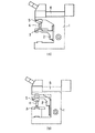
従来、顕微鏡として、図5(a)に示すように、顕微鏡本体1に上下方向に移動可能に設けられた移動台2に、サンプルを載置するステージ3を設け、このようなステージ3を顕微鏡本体1側に固定された対物レンズ4を有するレボルバ5に対して上下動させて焦準を行う方式のものが多く用いられているが、サンプルが重い場合や、サンプルを固定しなければならない場合(例えばマニュピレータとの間系でサンプルの高さ方向の位置を変えられない場合、サンプルを観察しながら組立作業を行うような場合)には、組み立て内容を一部変更することで、同図(b)に示すように、顕微鏡本体1に上下方向に移動可能に設けられた移動台2に対物レンズ4を有するレボルバ5を設け、このレボルバ5を顕微鏡本体1側に固定されたステージ3に対して上下動させて焦準を行う方式を選択できるようにしたものがある。
【0003】
ところで、このような顕微鏡には、落射照明としてケーラー照明が多く用いられている。図6は、このようなケーラー照明を説明する落射照明光学系を示すもので、図面では、照明光学系の主光線を示している。
【0004】
この場合、光源11から出射された照明光は、コレクタレンズ12でほぼ平行光束となり、リレーレンズ13により集光され、開口絞り14で焦点を結ぶ。また、開口絞り14を通った光束は、リレーレンズ15を介してハーフミラー16に入射され、ここで、反射された光束は、対物レンズ4の瞳位置(対物レンズの後側焦点位置)18で再度焦点を結び、対物レンズ4を構成するレンズ群4aを通ってサンプル19に照射される。一方、照明光が照射されたサンプル19の反射光は、対物レンズ4を通り、ハーフミラー16を透過して平行光束として結像レンズ20に入射、結像され、プリズム21を介して接眼レンズ22により観察される。
【0005】
このようなケーラー照明によれば、対物レンズ4の瞳位置と開口絞り14の光学的共役関係により、倍率の異なる対物レンズ4を使用しても、サンプル19にむらのない照明を行うことができる。また、開口絞り14には、絞り羽根などにより径を可変可能なものが用いられるが、この開口絞り14は、光源11と共役の位置にあるので、開口絞り14の径を小さくしても、照明光を視野全体に均一に減少させることができる。また、対物レンズ4の開口数に合わせて開口絞り14の径を変更することにより、照明の適正化を図ることができ、さらに、対物レンズ4の開口数に対して絞り径をを変えることで、照明のコントラスト、焦点深度を変化させることもできる。また、光軸上の光線23をサンプル19と共役の位置に配置される視野絞り24で焦点を結ばせることで、視野絞り24の径により視野の可変を行うこともできる。
【0006】
【発明が解決しようとする課題】
この場合、図5(a)に示すステージ3側を移動させる方式のものは、図6で述べたケーラー照明を採用する場合、顕微鏡本体1の上部に光源11からの照明光の光軸上にコレクタレンズ12、リレーレンズ13、開口絞り14、視野絞り24、リレーレンズ15およびハーフミラー16を有する落射投光管6が配置されるが、このような落射投光管6に対して対物レンズ4の位置が固定で、これら間の距離を常に一定にできるので、この距離を小さくできる光学的な有利さもあって何ら問題ない。
【0007】
ところが、図5(b)に示すレボルバ5側を移動させる方式のものは、レボルバ5の上下動により、対物レンズ4の瞳位置と落射投光管6との距離が変化するため、上述したケーラー照明の効果を期待することができない。
【0008】
そこで、従来、実開平3−55931号公報に開示されるように、開口絞りをリレーレンズとともに移動可能にする移動機構を設け、このような移動機構により開口絞りとリレーレンズを所定距離移動させて平行光束を伸縮させることで、対物レンズの瞳位置と開口絞りを光学的共役関係に保つ方法が知られている。
【0009】
ところが、このように特殊な移動機構を落射投光管内部に設けることは、開口絞りの操作部まで含めると光学的筒形状などを大幅に変更しなければならず、極力シンプルに抑えるべき汎用の落射投光管が大型で、コスト的に高価になってしまう。
【0010】
また、特開平10−73768号公報には、対物レンズの瞳位置の変化を補正するため、開口絞りの位置を切換えたり、別途設けるようにものが開示されているが、このようにしても開口絞りを別体にして移動させるのに変わりなく、上述したような特殊な移動機構を必要とする。
【0011】
本発明は上記事情に鑑みてなされたもので、対物レンズの瞳位置と開口絞りの関係を常に光学的共役位置に保つことができ、最適な照明効果を期待できるとともに、コスト的にも安価にできる顕微鏡装置を提供することを目的とする。
【0012】
【課題を解決するための手段】
請求項1記載の発明は、光源からの照明光を少なくとも開口絞りを有する光路を介して反射部材に入射させ、この反射部材で反射した光束を対物レンズに入射させるケーラー照明の落射照明光学系を構成する落射投光管を有する顕微鏡装置であって、前記反射部材を収容する第1反射部材ブロックと、前記反射部材を収容するととともに前記反射部材と前記開口絞りとの間に補助光学素子が配置されている第2反射部材ブロックと、を備えていて、前記第1反射部材ブロックと前記第2反射部材ブロックは、前記反射部材に対する前記対物レンズの瞳位置の移動に対応して選択的に前記落射投光管に配置され、前記開口絞りと前記対物レンズの瞳位置との光学的共役関係を保つ、ことを特徴としている。
【0013】
請求項2記載の発明は、請求項1記載の発明において、前記落射投光管には前記開口絞りと前記反射部材との間に配置され前記開口絞りからの光束を結像させるレンズが配置されていて、前記補助光学素子は前記レンズからの前記光束の結像位置を延ばす凹レンズである、ことを特徴としている。
【0014】
請求項3記載の発明は、請求項1または2記載の発明において、前記落射投光管には、前記光源と前記開口絞りとの間の光路で、前記開口絞りに近接して拡散板が配置されている、ことを特徴としている。
【0016】
この結果、本発明によれば、ケーラー照明の落射照明光学系の対物レンズの瞳位置と開口絞りの光学的共役関係を保つことができるので、ムラのない照明と開口絞りを機能させることができる。
【0017】
また、本発明によれば、顕微鏡の基幹ユニットを共通に利用できるので、各ユニットを最小限のコストで提供でき、これら各ユニットとともに複数の反射部材ブロックを用意するだけで、異なる方式の顕微鏡を構築できるので、経済的に有利にできる。
【0018】
さらに、本発明によれば、開口絞りの近傍に拡散板を配置したことで、照明光学系の変更による軸外光の収差による照明ムラや光源の投影倍率の僅かな差を補正し、通常使用時との差を極力目立たなくできる。
【0019】
さらにまた、本発明によれば、落射照明光学系と対物レンズの間の光路に中間部材として、中間ユニットや中間鏡筒を設けることができるので、つまり、対物レンズからの観察系平行光束部に中間部材を挿入できるので、光線の取り出し、別な光学系の付加などのシステム化に適した構成を得られる。
【0020】
【発明の実施の形態】
以下、本発明の実施の形態を図面に従い説明する。
【0021】
(第1の実施の形態)
図1および図2は、本発明が適用される顕微鏡装置の概略構成図で、図1は、ステージ側を焦準移動させる方式、図2は、対物レンズ側を焦準移動させる方式を示している。
【0022】
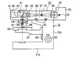
まず、図1は、ステージ側を焦準移動させる方式を適用したもので、図において、31は顕微鏡本体で、この顕微鏡本体31は、水平方向のベース31aに直立して胴部31bが設けられ、この胴部31bの上部には、ベース31aに対して平行な方向に落射投光管32がボルト30により直接取り付けられている。
【0023】
この落射投光管32は、ケーラー照明の落射照明光学系を構成するもので、点光源からなる光源33およびコレクタレンズ34を有するランプハウス35が設けられ、光源33から出射された照明光の光軸上に沿ってコレクタレンズ34、リレーレンズ36、開口絞り37、視野絞り38、リレーレンズ39および反射部材としてハーフミラー40が配置されている。この場合、ハーフミラー40は、反射部材ブロックを構成するキューブ41内に収容されている。このようなキューブ41は、複数個がキューブユニット42に収容され、選択的に落射投光管32の光軸上に切換えることができるようになっている。
【0024】
落射投光管32の先端部には、レボルバ44が設けられている。このレボルバ44には、複数の対物レンズ45が設けられ、レボルバ44の回転操作により、これら対物レンズ45を選択的に光軸上に切換え可能にしている。
【0025】
一方、顕微鏡本体31の胴部31bには、上下方向に沿ってガイド部46が形成され、このガイド部46に沿ってステージ受け部47が上下動可能に設けられている。このステージ受け部47には、サンプル48が載置されるステージ49が設けられ、ステージ受け部47の上下動によりステージ49を対物レンズ45の光軸方向に移動可能にしている。この場合、ステージ49は、顕微鏡本体31の側面に配置された焦準ハンドル50を回転操作することで胴部31b内部に設けられた図示しない焦準機構を介して上下動され、サンプル63を対物レンズ45の焦点位置に合わせるようにしている。
【0026】
このような方式の顕微鏡では、光源33から出射された照明光は、コレクタレンズ34でほぼ平行光束となり、リレーレンズ36により集光され、開口絞り37で結像される。その後、開口絞り37を通った光束は、リレーレンズ39を介してハーフミラー40に入射され、ここで、反射された光束は、対物レンズ45の瞳位置(対物レンズの後側焦点位置)51で再度結像され、対物レンズ45を通ってサンプル48に照射される。一方、サンプル48からの反射光は、対物レンズ45を通り、ハーフミラー40を透過して平行光束として図示しない結像レンズ、接眼レンズを介して観察される。
【0027】
このような方式の顕微鏡によれば、ケーラー照明の落射照明光学系を構成する落射投光管32は、対物レンズ45との間の距離を一定にしているので、上述したケーラー照明による利点を得られ、また、落射投光管32と対物レンズ45を最も近い距離で取り付けることもできるので、広い視野を照明、観察することができる。
【0028】
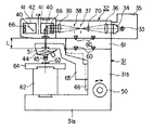
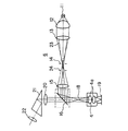
次に、図2は、図1に示す構成の一部を変更した対物レンズ側を焦準移動させる方式を採用したもので、ここでは、図1と同一部分には、同符号を付している。
【0029】
この場合、顕微鏡本体31の胴部31b上には、所定高さ寸法の嵩上げスペーサ61を介して落射投光管32がボルト60により取り付けられている。
【0030】
また、顕微鏡本体31のベース31a上には、ステージ受け部62が図示しないアリなどにより着脱可能に設けられ、このステージ受け部62に、サンプル63を載置したステージ64が設けられている。
【0031】
一方、顕微鏡本体31の胴部31bの上下方向に沿って形成されるガイド部46には、対物アーム65が設けられ、ガイド部46に沿って上下動可能にしている。また、対物アーム65の先端には、レボルバ44が設けられ、対物アーム65の上下動によりレボルバ44をステージ64に対して光軸方向に移動可能にしている。この場合、レボルバ44は、顕微鏡本体31の側面に配置された焦準ハンドル50を回転操作することで胴部31b内部に設けられた図示しない焦準機構を介して上下動され、サンプル63を対物レンズ45の焦点位置に合わせるようにしている。
【0032】
また、落射投光管32のキューブユニット42に収容される反射部材ブロックを構成する複数のキューブ41は、それぞれ反射部材のハーフミラー40の前面に、補助光学素子として凹レンズ66が配置されている。この凹レンズ66は、リレーレンズ39の焦点距離を延ばし、ハーフミラー40に入射される光束の光線角度をやや浅くして、ハーフミラー40で反射された光束を対物レンズ45の瞳位置で結像させるためのものである。つまり、この場合、対物アーム65の厚み寸法および上下動ストロークにより、落射投光管32と対物レンズ45の距離がLだけ伸びた分、凹レンズ66によりリレーレンズ39の焦点距離を延ばすようにしている。
【0033】
その他は、図1と同様なので、ここでの説明は省略する。
【0034】
このようなステージ側を焦準移動させる方式の顕微鏡では、光源33から出射された照明光は、コレクタレンズ34でほぼ平行光束となり、リレーレンズ36により集光され、開口絞り37で結像される。その後、開口絞り37よりリレーレンズ39を通った光束は、凹レンズ66を介してハーフミラー40に入射される。この場合、凹レンズ66によりリレーレンズ39の焦点距離が延ばされ、ハーフミラー40で反射された光束は、対物レンズ45の瞳位置(対物レンズの後側焦点位置)51で再度結像され、対物レンズ45を通ってサンプル48に照射される。一方、サンプル48からの反射光は、対物レンズ45を通り、ハーフミラー40を透過して平行光束として図示しない結像レンズ、接眼レンズを介して観察される。
【0035】
このような対物レンズ側を焦準移動させる方式の顕微鏡によれば、ケーラー照明の落射照明光学系を構成する落射投光管32は、ハーフミラー40の前面に、補助光学素子として凹レンズ66を配置し、この凹レンズ66により、リレーレンズ39の焦点距離を延ばし、ハーフミラー40に入射される光束の光線角度をやや浅くして、ハーフミラー40で反射した光束を対物レンズ45の瞳位置51で結像させるようにしたので、落射投光管32と対物レンズ45の距離がLだけ伸びた場合も、対物レンズ45の瞳位置と開口絞り37の光学的共役関係を保つことができ、ケーラー照明による全ての利点を確保することができる。特に、落射照明において重要な開口絞りの性能を確保できるので、開口絞りの径を小さくしても、照明光がケラれる(照野が狭くなる)ことがなく、照明光を視野全体に均一に減少させることができる。
【0036】
なお、ハーフミラー40の前面に凹レンズ66を挿入すると、光路が延び、光線角度が浅くなることから、軸外光が減少し、照野が狭くなって、軸上光線の結像位置が視野絞り38の位置から移動してしまうことがあるが、ケーラー照明の性能については確保される。また、落射照明の場合、視野絞りは、視野周辺でのフレア防止のために最適な径にする必要があるが、その他は、対物レンズの倍率に関わらず一定の径であるので、固定してあるか特に使用しないことが多い。
【0037】
従って、このような第1の実施の形態によれば、ステージ側を焦準移動させる方式および対物レンズ側を焦準移動させる方式のいずれの構成に対しても、ケーラー照明の落射照明光学系を構成する落射投光管32における開口絞り14と対物レンズ4の瞳位置との光学的共役関係を保つことができるので、ムラのない照明と開口絞りを機能させることができ、常に最適な照明光効果を期待することができる。また、これらの方式のいずれに対しても、顕微鏡の基幹ユニットである顕微鏡本体1、落射投光管32レボルバ44などを共通に利用できるので、各ユニットを最小限のコストで提供でき、これら各ユニットとともに複数の反射部材ブロックを用意するだけで、それぞれの方式の顕微鏡を構築できるので、経済的に極めて有利にできる。
【0038】
なお、上述した図1および図2において、光源33と開口絞り37との間の光路上で、開口絞り37の近傍に拡散板70を配置するようにしてもよい。このような拡散板70は、通常、光源のフィラメント形状の相違や輝度差によるむらの抑制のために配置されるが、ここでは、照明光学系の変更による軸外光の収差による照明ムラや光源の投影倍率の僅かな差を補正し、通常使用時との差を極力目立たなくするのに効果的である。
【0039】
(第2の実施の形態)
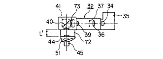
図3は、本発明の第2の実施の形態の要部の概略構成を示すもので、図1と同一部分には、同符号を付している。
【0040】
この場合、ステージ側を焦準移動させる方式の顕微鏡で、落射照明光学系と対物レンズ45の間の光路、つまり、落射投光管32とレボルバ44との間に中間部材として、中間ユニット72を挿入している。この場合、中間ユニット72は、例えば対物レンズ45に近いほど効果的な輪帯照明、補助照明装置、オートフォーカス、微細な焦準装置(ピエゾ素子を用いた焦点合わせユニットなどである。
【0041】
また、落射投光管32のキューブユニット42に収容される複数のキューブ41は、ハーフミラー40の前面に、補助光学素子として凹レンズ73が配置されている。この凹レンズ73は、リレーレンズ39の焦点距離を延ばし、ハーフミラー40に入射される光束の光線角度をやや浅くして、ハーフミラー40で反射された光束を対物レンズ45の瞳位置で結像させるためのもので、中間ユニット72の挿入により落射投光管32と対物レンズ45の距離がL’だけ伸びた分、凹レンズ73によりリレーレンズ39の焦点距離を延ばすようにしている。
【0042】
このようにしても、対物レンズ45の瞳位置51と開口絞り37の光学的共役関係を保つことができるので、ムラのない照明と開口絞りを機能させることができ、さらに、顕微鏡本体1、落射投光管32レボルバ44などを共通に利用でき、しかも、これらユニットとともに複数の反射部材ブロックを用意するだけで、それぞれの方式の顕微鏡を構築できるので、経済的に極めて有利にできる。さらに、対物レンズ45からの観察系平行光束部(無限遠光束)部に中間ユニット72が挿入できるので、光線の取り出し、別な光学系の付加などのシステム化に適した構成を得ることができる。
【0043】
(第3の実施の形態)
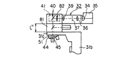
図4は、本発明の第3の実施の形態の要部の概略構成を示すもので、図1と同一部分には、同符号を付している。
【0044】
この場合、顕微鏡本体31の胴部31bの上部には、ベース31aに対して平行な方向に対物アーム31cが一体に形成され、この対物アーム31cの上方に中間鏡筒81を介して落射投光管32が設けられるとともに、対物アーム31cの下方にレボルバ44が設けられている。つまり、この場合も、落射照明光学系と対物レンズ45の間の光路に中間部材として、中間鏡筒81を設けるようにしている。
【0045】
また、落射投光管32のキューブユニット42に収容されるキューブ41は、ハーフミラー40の前面に、補助光学素子として凹レンズ82が配置されている。この凹レンズ82は、リレーレンズ39の焦点距離を延ばし、ハーフミラー40に入射される光束の光線角度をやや浅くして、ハーフミラー40で反射された光束を対物レンズ45の瞳位置で結像させるためのもので、中間鏡筒81の挿入により落射投光管32と対物レンズ45の距離がL’’だけ伸びた分、凹レンズ82によりリレーレンズ39の焦点距離を延ばすようにしている。
【0046】
このようにしても、第2の実施の形態と同様な効果を期待できる。
【0047】
【発明の効果】
以上述べたように本発明によれば、対物レンズの瞳位置と開口絞りの関係を常に光学的共役位置に保つことができ、最適な照明効果を期待できるとともに、コスト的にも安価にできる顕微鏡装置を提供できる。
【図面の簡単な説明】
【図1】本発明の第1の実施の形態のステージ側を焦準移動させる方式の顕微鏡の概略構成を示す図。
【図2】第1の実施の形態のレボルバ側を移動させる方式の顕微鏡の概略構成を示す図。
【図3】本発明の第2の実施の形態の要部の概略構成を示す図。
【図4】本発明の第3の実施の形態の要部の概略構成を示す図。
【図5】従来の顕微鏡の概略構成を示す図。
【図6】ケーラー照明を説明する落射照明光学系を示す図。
【符号の説明】
30…ボルト
31…顕微鏡本体
31a…ベース
31b…胴部
31c…対物アーム
32…落射投光管
33…光源
34…コレクタレンズ
35…ランプハウス
36…リレーレンズ
37…開口絞り
38…視野絞り
39…リレーレンズ
40…ハーフミラー
41…キューブ
42…キューブユニット
44…レボルバ
45…対物レンズ
46…ガイド部
47…ステージ受け部
48…サンプル
49…ステージ
50…焦準ハンドル
51…瞳位置
60…ボルト
61…スペーサ
63…サンプル
64…ステージ
65…対物アーム
66…凹レンズ
70…拡散板
72…中間ユニット
73…凹レンズ
81…中間鏡筒
82…凹レンズ[0001]
BACKGROUND OF THE INVENTION
The present invention relates to a microscope apparatus using epi-illumination.
[0002]
[Prior art]
Conventionally, as shown in FIG. 5A, a microscope is provided with a
[0003]
By the way, in such a microscope, Koehler illumination is often used as epi-illumination. FIG. 6 shows an epi-illumination optical system for explaining such Koehler illumination. In the drawing, principal rays of the illumination optical system are shown.
[0004]
In this case, the illumination light emitted from the light source 11 becomes a substantially parallel light beam by the
[0005]
According to such Koehler illumination, the
[0006]
[Problems to be solved by the invention]
In this case, in the method of moving the
[0007]
However, the method of moving the
[0008]
Therefore, conventionally, as disclosed in Japanese Utility Model Publication No. 3-55931, a moving mechanism that enables the aperture stop to move together with the relay lens is provided, and the aperture stop and the relay lens are moved a predetermined distance by such a moving mechanism. There is known a method of keeping the pupil position of the objective lens and the aperture stop in an optical conjugate relationship by expanding and contracting the parallel light beam.
[0009]
However, providing such a special moving mechanism inside the epi-illumination tube requires that the optical cylinder shape, etc. must be significantly changed if it includes the operation part of the aperture stop. The incident-light projection tube is large and expensive.
[0010]
Japanese Patent Laid-Open No. 10-73768 discloses that the position of the aperture stop is switched or provided separately in order to correct the change in the pupil position of the objective lens. A special moving mechanism as described above is required, as is the case where the diaphragm is moved separately.
[0011]
The present invention has been made in view of the above circumstances, and the relationship between the pupil position of the objective lens and the aperture stop can always be maintained at the optical conjugate position, so that an optimal illumination effect can be expected and the cost can be reduced. An object of the present invention is to provide a microscope apparatus that can be used.
[0012]
[Means for Solving the Problems]
According to a first aspect of the present invention, there is provided an epi-illumination optical system for Koehler illumination in which illumination light from a light source is incident on a reflecting member through an optical path having at least an aperture stop, and a light beam reflected by the reflecting member is incident on an objective lens. a microscope apparatus having a vertical illuminator constituting an auxiliary optical element disposed between the first reflecting member blocks containing said reflecting member and for accommodating the reflecting member and the reflecting member with said aperture stop A second reflecting member block, wherein the first reflecting member block and the second reflecting member block selectively correspond to the movement of the pupil position of the objective lens relative to the reflecting member. It is arranged in an epi-illumination projection tube, and maintains an optical conjugate relationship between the aperture stop and the pupil position of the objective lens .
[0013]
According to a second aspect of the present invention, in the first aspect of the present invention, the incident light projection tube is provided with a lens that is disposed between the aperture stop and the reflecting member and forms an image of a light beam from the aperture stop. The auxiliary optical element is a concave lens that extends the imaging position of the light beam from the lens .
[0014]
According to a third aspect of the invention, in the invention of claim 1 or 2, wherein the vertical illuminator, the optical path, the diffusion plate close to the aperture stop is disposed between the aperture stop and the light source It is characterized by being.
[0016]
As a result, according to the present invention, the optical conjugate relationship between the pupil position of the objective lens of the epi-illumination optical system of the Koehler illumination and the aperture stop can be maintained, so that the illumination and aperture stop without unevenness can function. .
[0017]
Further, according to the present invention, since the basic unit of the microscope can be used in common, each unit can be provided at a minimum cost, and by preparing a plurality of reflecting member blocks together with each unit, different types of microscopes can be provided. Since it can be constructed, it can be economically advantageous.
[0018]
Furthermore, according to the present invention, the diffuser plate is arranged in the vicinity of the aperture stop, thereby correcting illumination unevenness due to aberration of off-axis light due to the change of the illumination optical system and a slight difference in the projection magnification of the light source. The difference from time can be made as inconspicuous as possible.
[0019]
Furthermore, according to the present invention, an intermediate unit or an intermediate lens barrel can be provided as an intermediate member in the optical path between the epi-illumination optical system and the objective lens, that is, in the observation system parallel light beam portion from the objective lens. Since the intermediate member can be inserted, it is possible to obtain a configuration suitable for systemization such as extraction of a light beam and addition of another optical system.
[0020]
DETAILED DESCRIPTION OF THE INVENTION
Hereinafter, embodiments of the present invention will be described with reference to the drawings.
[0021]
(First embodiment)
FIG. 1 and FIG. 2 are schematic configuration diagrams of a microscope apparatus to which the present invention is applied. FIG. 1 shows a method for focusing on the stage side, and FIG. 2 shows a method for focusing on the objective lens side. Yes.
[0022]
First, FIG. 1 is an application of a method of moving the stage side in focus. In the figure,
[0023]
The epi-
[0024]
A
[0025]
On the other hand, a
[0026]
In such a type of microscope, the illumination light emitted from the
[0027]
According to the microscope of this type, since the epi-
[0028]
Next, FIG. 2 adopts a method of focusing and moving the objective lens side in which a part of the configuration shown in FIG. 1 is changed. Here, the same parts as those in FIG. Yes.
[0029]
In this case, the epi-
[0030]
On the base 31 a of the microscope
[0031]
On the other hand, an
[0032]
The plurality of
[0033]
Others are the same as those in FIG. 1, and the description thereof is omitted here.
[0034]
In such a microscope that moves on the stage side, the illumination light emitted from the
[0035]
According to such a microscope that moves the objective lens side in focus, the epi-
[0036]
If the
[0037]
Therefore, according to such a first embodiment, the epi-illumination optical system for Koehler illumination is used for both the system for focusing on the stage side and the system for focusing on the objective lens side. Since the optical conjugate relationship between the
[0038]
In FIGS. 1 and 2 described above, the
[0039]
(Second Embodiment)
FIG. 3 shows a schematic configuration of a main part of the second embodiment of the present invention. The same reference numerals are given to the same parts as those in FIG.
[0040]
In this case, an
[0041]
Further, in the plurality of
[0042]
Even in this case, since the optical conjugate relationship between the
[0043]
(Third embodiment)
FIG. 4 shows a schematic configuration of the main part of the third embodiment of the present invention. The same reference numerals are given to the same parts as those in FIG.
[0044]
In this case, an
[0045]
The
[0046]
Even if it does in this way, the effect similar to 2nd Embodiment can be anticipated.
[0047]
【The invention's effect】
As described above, according to the present invention, the relationship between the pupil position of the objective lens and the aperture stop can always be maintained at the optical conjugate position, and an optimal illumination effect can be expected and the microscope can be inexpensive. Equipment can be provided.
[Brief description of the drawings]
FIG. 1 is a diagram showing a schematic configuration of a microscope of a system for moving a stage side according to a first embodiment of the present invention.
FIG. 2 is a diagram showing a schematic configuration of a microscope that moves the revolver according to the first embodiment;
FIG. 3 is a diagram showing a schematic configuration of a main part of a second embodiment of the present invention.
FIG. 4 is a diagram showing a schematic configuration of a main part of a third embodiment of the present invention.
FIG. 5 is a diagram showing a schematic configuration of a conventional microscope.
FIG. 6 is a diagram showing an epi-illumination optical system for explaining Koehler illumination.
[Explanation of symbols]
30 ...
Claims (3)
前記反射部材を収容する第1反射部材ブロックと、
前記反射部材を収容するととともに、前記反射部材と前記開口絞りとの間に補助光学素子が配置されている第2反射部材ブロックと、
を備えていて、
前記第1反射部材ブロックと前記第2反射部材ブロックは、前記反射部材に対する前記対物レンズの瞳位置の移動に対応して選択的に前記落射投光管に配置され、前記開口絞りと前記対物レンズの瞳位置との光学的共役関係を保つ、
ことを特徴とする顕微鏡装置。There is an epi-illumination light pipe that constitutes an epi- illumination optical system for Koehler illumination that makes illumination light from a light source enter at least a reflecting member through an optical path having an aperture stop and makes a light beam reflected by the reflecting member enter an objective lens. a microscope apparatus,
A first reflecting member block that houses the reflecting member;
A second reflecting member block in which an auxiliary optical element is disposed between the reflecting member and the aperture stop;
With
The first reflecting member block and the second reflecting member block are selectively disposed in the incident light projection tube in response to movement of a pupil position of the objective lens with respect to the reflecting member, and the aperture stop and the objective lens Maintain optical conjugate relationship with the pupil position of
A microscope apparatus characterized by that.
前記補助光学素子は、前記レンズからの前記光束の結像位置を延ばす凹レンズである、
ことを特徴とする請求項1に記載の顕微鏡装置。 In the epi-illumination projection tube, a lens that is disposed between the aperture stop and the reflection member and forms an image of a light beam from the aperture stop is disposed.
The auxiliary optical element is a concave lens that extends the imaging position of the light beam from the lens.
The microscope apparatus according to claim 1.
Priority Applications (1)
| Application Number | Priority Date | Filing Date | Title |
|---|---|---|---|
| JP2001081120A JP4792163B2 (en) | 2001-03-21 | 2001-03-21 | Microscope equipment |
Applications Claiming Priority (1)
| Application Number | Priority Date | Filing Date | Title |
|---|---|---|---|
| JP2001081120A JP4792163B2 (en) | 2001-03-21 | 2001-03-21 | Microscope equipment |
Publications (3)
| Publication Number | Publication Date |
|---|---|
| JP2002277749A JP2002277749A (en) | 2002-09-25 |
| JP2002277749A5 JP2002277749A5 (en) | 2008-04-17 |
| JP4792163B2 true JP4792163B2 (en) | 2011-10-12 |
Family
ID=18937278
Family Applications (1)
| Application Number | Title | Priority Date | Filing Date |
|---|---|---|---|
| JP2001081120A Expired - Fee Related JP4792163B2 (en) | 2001-03-21 | 2001-03-21 | Microscope equipment |
Country Status (1)
| Country | Link |
|---|---|
| JP (1) | JP4792163B2 (en) |
Families Citing this family (5)
| Publication number | Priority date | Publication date | Assignee | Title |
|---|---|---|---|---|
| JP4683853B2 (en) * | 2003-04-04 | 2011-05-18 | オリンパス株式会社 | Total reflection fluorescence microscope |
| JP4532852B2 (en) * | 2003-06-09 | 2010-08-25 | オリンパス株式会社 | Polarization microscope and polarization observation intermediate tube |
| JP5464773B2 (en) * | 2005-07-27 | 2014-04-09 | オリンパス株式会社 | Stage unit |
| JP5055568B2 (en) * | 2006-02-17 | 2012-10-24 | 株式会社ニコン | Phase contrast microscope |
| DE102010039950B4 (en) * | 2010-08-30 | 2021-07-22 | Leica Microsystems Cms Gmbh | Microscope with micro and macro objectives |
Family Cites Families (4)
| Publication number | Priority date | Publication date | Assignee | Title |
|---|---|---|---|---|
| JPS6344813Y2 (en) * | 1982-03-19 | 1988-11-21 | ||
| JPS5968313U (en) * | 1982-10-28 | 1984-05-09 | オリンパス光学工業株式会社 | Epi-illumination optical system of an infinity-corrected epi-illumination microscope |
| JP3289941B2 (en) * | 1992-03-13 | 2002-06-10 | オリンパス光学工業株式会社 | System microscope |
| JP3841484B2 (en) * | 1996-07-25 | 2006-11-01 | オリンパス株式会社 | Microscope epi-illumination system |
-
2001
- 2001-03-21 JP JP2001081120A patent/JP4792163B2/en not_active Expired - Fee Related
Also Published As
| Publication number | Publication date |
|---|---|
| JP2002277749A (en) | 2002-09-25 |
Similar Documents
| Publication | Publication Date | Title |
|---|---|---|
| US5737121A (en) | Real time scanning optical macroscope | |
| US7042638B2 (en) | Device for coupling light into a microscope | |
| US20040240046A1 (en) | Microscope | |
| JP5286774B2 (en) | Microscope device and fluorescent cube used therefor | |
| JPH08190056A (en) | Optical observation device | |
| US5764408A (en) | Lens-barrel optical system and microscope apparatus | |
| JP2000019412A (en) | Dark field illumination device and dark field illumination method | |
| US6917468B2 (en) | Confocal microscope | |
| JP3544564B2 (en) | Microscope equipment | |
| US20070146872A1 (en) | Invertible light-optical microscope | |
| US7551351B2 (en) | Microscope with evanescent sample illumination | |
| US20090153956A1 (en) | Microscope illumination apparatus | |
| JPWO2009142312A1 (en) | Microscope equipment | |
| JP4792163B2 (en) | Microscope equipment | |
| TWI417568B (en) | Microscope | |
| JP4434612B2 (en) | Microscope and zoom objective | |
| JP5084183B2 (en) | Epi-illumination optical system for microscope | |
| JP2002023061A (en) | Microscope dark field illumination device and dark field illumination method | |
| JP4370404B2 (en) | DLP type evanescence microscope | |
| JPH075397A (en) | Schlieren microscope equipment | |
| JP4470247B2 (en) | Inverted microscope | |
| JPH11194277A (en) | Inverted microscope | |
| JPH0695001A (en) | Microscopic device | |
| US8817368B2 (en) | Lens for evanescent wave illumination and corresponding microscope | |
| JP2007264322A (en) | Infrared microscope |
Legal Events
| Date | Code | Title | Description |
|---|---|---|---|
| A521 | Written amendment |
Free format text: JAPANESE INTERMEDIATE CODE: A523 Effective date: 20080305 |
|
| A621 | Written request for application examination |
Free format text: JAPANESE INTERMEDIATE CODE: A621 Effective date: 20080305 |
|
| A977 | Report on retrieval |
Free format text: JAPANESE INTERMEDIATE CODE: A971007 Effective date: 20110413 |
|
| A131 | Notification of reasons for refusal |
Free format text: JAPANESE INTERMEDIATE CODE: A131 Effective date: 20110510 |
|
| A521 | Written amendment |
Free format text: JAPANESE INTERMEDIATE CODE: A523 Effective date: 20110627 |
|
| TRDD | Decision of grant or rejection written | ||
| A01 | Written decision to grant a patent or to grant a registration (utility model) |
Free format text: JAPANESE INTERMEDIATE CODE: A01 Effective date: 20110719 |
|
| A01 | Written decision to grant a patent or to grant a registration (utility model) |
Free format text: JAPANESE INTERMEDIATE CODE: A01 |
|
| A61 | First payment of annual fees (during grant procedure) |
Free format text: JAPANESE INTERMEDIATE CODE: A61 Effective date: 20110725 |
|
| FPAY | Renewal fee payment (event date is renewal date of database) |
Free format text: PAYMENT UNTIL: 20140729 Year of fee payment: 3 |
|
| LAPS | Cancellation because of no payment of annual fees |