JP4828215B2 - Elevator control device - Google Patents
Elevator control device Download PDFInfo
- Publication number
- JP4828215B2 JP4828215B2 JP2005346219A JP2005346219A JP4828215B2 JP 4828215 B2 JP4828215 B2 JP 4828215B2 JP 2005346219 A JP2005346219 A JP 2005346219A JP 2005346219 A JP2005346219 A JP 2005346219A JP 4828215 B2 JP4828215 B2 JP 4828215B2
- Authority
- JP
- Japan
- Prior art keywords
- car
- inspection operation
- rope
- governor
- control unit
- Prior art date
- Legal status (The legal status is an assumption and is not a legal conclusion. Google has not performed a legal analysis and makes no representation as to the accuracy of the status listed.)
- Active
Links
- 238000007689 inspection Methods 0.000 claims description 57
- 238000001514 detection method Methods 0.000 claims description 28
- 230000005856 abnormality Effects 0.000 claims description 18
- 239000000725 suspension Substances 0.000 claims description 14
- 238000000034 method Methods 0.000 claims description 9
- 238000012935 Averaging Methods 0.000 claims description 8
- 238000005303 weighing Methods 0.000 claims description 8
- 230000007423 decrease Effects 0.000 claims description 2
- 241000555745 Sciuridae Species 0.000 claims 1
- 238000010586 diagram Methods 0.000 description 14
- 238000004364 calculation method Methods 0.000 description 10
- 238000012545 processing Methods 0.000 description 10
- 238000012937 correction Methods 0.000 description 8
- 230000002159 abnormal effect Effects 0.000 description 4
- 238000012790 confirmation Methods 0.000 description 4
- 238000012423 maintenance Methods 0.000 description 4
- 238000011084 recovery Methods 0.000 description 4
- 238000004804 winding Methods 0.000 description 2
- 238000012544 monitoring process Methods 0.000 description 1
Images


Landscapes
- Maintenance And Inspection Apparatuses For Elevators (AREA)
Description
この発明は、例えば地震によりかごが停止された後などにかごを自動的に走行させて異常の有無を点検する点検運転制御部を有するエレベータ制御装置に関するものである。 The present invention relates to an elevator control device having an inspection operation control unit that automatically checks the presence or absence of an abnormality by causing the car to automatically travel after the car has been stopped due to an earthquake, for example.
従来のエレベータの地震時管制運転装置では、地震によるかごの停止後に、かご内に乗客が残っていないことが確認されると、かごの点検運転が開始される。点検運転では、かご上に設けられた異常検出装置により、異常音や異常振動の有無が確認される(例えば、特許文献1参照)。 In a conventional elevator operation control system for an earthquake, when it is confirmed that no passengers remain in the car after the car is stopped due to the earthquake, the car inspection operation is started. In the inspection operation, the presence or absence of abnormal noise or abnormal vibration is confirmed by an abnormality detection device provided on the car (see, for example, Patent Document 1).
上記のような従来の地震時管制運転装置では、例えば調速機ロープや主索の引っ掛かりが生じても、どの部分に引っ掛かりが生じたかが分からず、保守員が引っ掛かり部分を見つけるまでに時間がかかり、復旧までに要する時間が長くなってしまう。 With the conventional seismic control operation device as described above, for example, even if a governor rope or main rope is caught, it is not known which part is caught, and it takes time for maintenance personnel to find the caught part. , It takes a long time to recover.
この発明は、上記のような課題を解決するためになされたものであり、索状体の引っ掛かりが生じた場合の復旧に要する時間を短縮することができるエレベータ制御装置を得ることを目的とする。 The present invention has been made to solve the above-described problems, and an object of the present invention is to provide an elevator control device that can shorten the time required for recovery when a cord-like body is caught. .
この発明に係るエレベータ制御装置は、点検運転中に複数のエレベータ機器から入力された信号に基づいて、昇降路内の索状体の引っ掛かりの有無及び引っ掛かり部分を判定し、判定結果を表示するための信号を出力する点検運転制御部を用いたものである。 The elevator control device according to the present invention determines the presence or absence and a hooked portion of a cord-like body in a hoistway based on signals input from a plurality of elevator devices during an inspection operation, and displays the determination result The inspection operation control unit that outputs the above signal is used.
この発明のエレベータ制御装置は、点検運転中に複数のエレベータ機器から入力された信号に基づいて、索状体の引っ掛かり部分を判定し、判定結果を表示するための信号を出力するので、保守員が引っ掛かり部分を速やかに見つけることができ、復旧に要する時間を短縮することができる。 The elevator control device according to the present invention determines a hooked portion of the cord-like body based on signals input from a plurality of elevator devices during the inspection operation, and outputs a signal for displaying the determination result. Can quickly find the hooked portion, and the time required for recovery can be shortened.
以下、この発明を実施するための最良の形態について、図面を参照して説明する。
実施の形態1.
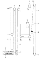
図1はこの発明の実施の形態1によるエレベータ装置を示す構成図である。図において、昇降路の下部には、巻上機1が設置されている。巻上機1は、駆動シーブ、駆動シーブを回転させるモータ、及び駆動シーブの回転を制動するブレーキを有している。また、巻上機1には、巻上機1の回転軸の回転に応じた信号を発生する回転検出器としての巻上機エンコーダ2が設けられている。
The best mode for carrying out the present invention will be described below with reference to the drawings.
1 is a block diagram showing an elevator apparatus according to
駆動シーブには、複数本(図では1本のみ示す)の主索3が巻き掛けられている。かご4及び釣合おもり5は、主索3により昇降路内に吊り下げられ、巻上機1の駆動力により昇降される。主索3は、第1及び第2の端部3a,3bを有している。第1及び第2の端部3a,3bは、昇降路の上部に設けられた綱止め部に接続されている。
A plurality of main ropes 3 (only one is shown in the figure) are wound around the drive sheave. The
かご4の下部には、かご吊り車6a,6bが搭載されている。釣合おもり5の上部には、釣合おもり吊り車7が搭載されている。昇降路の上部には、第1及び第2の返し車8,9が設けられている。主索3は、第1の端部3a側から順に、かご吊り車6a,6b、第1の返し車8、駆動シーブ、第2の返し車9、及び釣合おもり吊り車7に巻き掛けられている。即ち、かご4及び釣合おもり5は、2:1ローピング方式で昇降路内に吊り下げられている。
昇降路の上部には、調速機10が設置されている。調速機10には、調速機シーブ、過速度検出スイッチ及びロープキャッチ等が設けられている。調速機シーブには、調速機ロープ11が巻き掛けられている。調速機ロープ11の両端部は、かご4に搭載された非常止め装置(図示せず)の操作機構12に接続されている。調速機ロープ11の下端部は、昇降路の下部に配置された張り車13に巻き掛けられている。
A speed governor 10 is installed in the upper part of the hoistway. The governor 10 is provided with a governor sheave, an overspeed detection switch, a rope catch, and the like. A
かご4が昇降されると、調速機ロープ12が循環され、かご4の走行速度に応じた回転速度で調速機シーブが回転される。調速機10では、かご4の走行速度が過速度に達したことが機械的に検出される。また、調速機10には、調速機シーブの回転に応じた信号を発生する回転検出器としてのガバナエンコーダ14が設けられている。
When the
主索3の第1の端部3aが接続された綱止め部には、かご4内の負荷に応じた信号(秤信号)を発生する秤装置15が設けられている。かご4上には、昇降路内の異常音を検出するための集音マイク16が搭載されている。
A
巻上機1の運転は、エレベータ制御装置17により制御される。巻上機エンコーダ2、ガバナエンコーダ14、秤装置15及び集音マイク16からの信号は、エレベータ制御装置17に入力される。エレベータ制御装置17は、かご4を自動的に走行させて異常の有無を点検する点検運転制御部18を有している。
The operation of the
エレベータ制御装置17は、演算処理部(CPU)、記憶部(ROM、RAM及びハードディスク等)及び信号入出力部を持ったコンピュータを有している。点検運転制御部18の機能は、コンピュータにより実現される。即ち、コンピュータの記憶部には、点検運転制御部18の機能(引っ掛かり部分を推定する処理アルゴリズムを含む)を実現するための制御プログラムが格納されている。演算処理部は、制御プログラムに基づいて、点検運転制御部18の機能に関する演算処理を実行する。
The
ここで、図1の例では、地震の揺れ等により引っ掛かりが生じる可能性のある索状体として、主索3及び調速機ロープ11を挙げることができる。また、これらの索状体は、第1〜第9の部分21〜29に分けることができる。
Here, in the example of FIG. 1, the
即ち、第1の部分21は、主索3の第2の端部3bから釣合おもり吊り車7までの部分である。第2の部分22は、主索3の釣合おもり吊り車7から第2の返し車9までの部分である。第3の部分23は、主索3の第2の返し車9から駆動シーブまでの部分である。第4の部分24は、主索3の駆動シーブから第1の返し車8までの部分である。第5の部分25は、主索3の第1の返し車8からかご吊り車6bまでの部分である。第6の部分は、主索3のかご吊り車6aから第1の端部3aまでの部分である。
That is, the
第7の部分27は、調速機ロープ11のかご4に連結されている側で、連結部である操作機構12よりも上の部分である。第8の部分28は、調速機ロープ11のかご4に連結されている側で、操作機構12よりも下の部分である。第9の部分は、調速機ロープ11のかご4に連結されていない側の部分である。なお、図1は第8の部分28が昇降路機器等の引っ掛かり部19に引っ掛かった状態を示している。
The
点検運転制御部18は、点検運転中に複数のエレベータ機器から入力された信号に基づいて、昇降路内の索状体の引っ掛かりの有無及び引っ掛かり部分を判定し、判定結果を表示するための信号を出力する。具体的には、点検運転制御部18は、かご4の走行方向と、巻上機1のトルク信号と、秤装置15からの秤信号とに基づいて、索状体の引っ掛かり部分を判定する。
The inspection
次に、点検運転について説明する。地震等によりかご4が最寄り階に停止されると、点検運転制御部18は、地震の揺れが検出されなくなるとともに、かご4内に乗客が残っていないことを確認した上で点検運転を開始する。点検運転では、索状体の引っ掛かり等により機器が損傷するのを避けるため、通常点検時の低速運転(例えば15m/分)よりもさらに遅い超低速(例えば4m/分以下)でかご4が走行される。
Next, the inspection operation will be described. When the
図2は図1のかご4を点検運転で下方へ走行させた状態を示す構成図である。第8の部分28が引っ掛かり部分であるとすると、かご4は図2の状態から下方へは走行できなくなり、かご4が擬似的に軽くなり、秤装置15で検出される負荷が低下する。また、かご4が擬似的に軽くなると、かご4と釣合おもり5との重量差が大きくなることになり、釣合おもり5を支えるために必要な巻上機1のトルクが大きくなる。
FIG. 2 is a block diagram showing a state in which the
図3は図1のかご4を図2の位置まで点検運転で走行させた場合の巻上機電流及び秤信号の変化を示すグラフである。図3において、巻上機電流が異常検出レベルを超え、かつ秤信号が異常検出レベル以下となることにより、点検運転制御部18は、第8の部分28で引っ掛かりが発生していると判断する。
FIG. 3 is a graph showing changes in the hoisting machine current and the scale signal when the
図4は図1の第1の部分21に引っ掛かりが発生した場合の巻上機電流及び秤信号の変化を示すグラフである。第1の部分21に引っ掛かりが発生すると、釣合おもり5が引っ掛かり部から上へは行けなくなるにも拘わらず、巻上機1が回転しようとするので、巻上機1のトルク電流は増加する。しかし、第4〜第6の部分24〜26の張力は変わらないため、秤信号は変化しない。このような状況は、第2の部分22に引っ掛かりが発生した場合も同様である。
FIG. 4 is a graph showing changes in the hoisting machine current and the weighing signal when the
図5は図1の点検運転制御部18により引っ掛かり部分を判定するための判定基準を示す説明図である。エレベータ制御装置17の記憶部には、このような判定基準や異常検出レベルが予め設定され登録されている。
FIG. 5 is an explanatory diagram showing a criterion for determining a hooked portion by the inspection
図6は図1の点検運転制御部18による点検運転の動作を示すフローチャートである。点検運転による検査が開始されると、まずかご位置及び運転方向を確認する(ステップS1)。この後、トルク電流が異常検出レベルを超えたかどうかと(ステップS2)、秤電流が異常検出レベルを超えたかどうか(ステップS3)を確認する。いずれも異常検出レベルを超えていなければ、トルク電流及び秤電流の監視を継続しながら点検運転を継続する(ステップS4)。
FIG. 6 is a flowchart showing the operation of the inspection operation by the inspection
トルク電流及び秤電流の少なくともいずれか一方が異常検出レベルを超えると、引っ掛かりが発生していると判断し、かご4の走行を停止させる(ステップS5)。この後、上記のような方法で引っ掛かり部分を判定する(ステップS6)。そして、引っ掛かりが発生したことを保守センターに発報するとともに、引っ掛かり部分が特定されれば、特定された引っ掛かり部分の情報を保守センターに発報する(ステップS7)。又は、トルク電流及び秤電流のいずれか一方が異常検出レベルを超えても、他方が超えていない場合は、点検運転速度を落として点検を続け、異常検出レベルを超えた方の検出値のレベルがさらに上がるか、又は他方の検出値が上がり始めたら、引っ掛かりと判定するようにしてもよい。このようにすると、誤判定を低減することができる。
When at least one of the torque current and the weighing current exceeds the abnormality detection level, it is determined that the catch has occurred, and the traveling of the
このようなエレベータ制御装置17によれば、点検運転中に複数のエレベータ機器から入力された信号に基づいて、索状体の引っ掛かり部分を判定し、判定結果を表示するための信号を出力するので、保守員が引っ掛かり部分を速やかに見つけることができ、復旧に要する時間を短縮することができる。また、保守員が引っ掛かり部分に応じた保守部品をある程度特定して用意して現場に行くことができるので、これによっても復旧に要する時間を短縮することができる。
According to such an
なお、上記の例では引っ掛かり部分の情報を保守センターに発報するようにしたが、例えばエレベータ装置の制御盤や操作盤等に表示するようにしてもよい。
また、上記の例では、第1、第2及び第8の部分21,22,28の引っ掛かりを判定したが、図5に示したような判定基準を追加することにより、他の部分の引っ掛かりを判定することも可能である。
さらに、上記の例では、下方向へ点検運転を行う場合について示したが、上方向への点検運転で引っ掛かり部分を判定するようにしてもよい。
さらにまた、上記の例では、引っ掛かり部分の判定の対象となる索状体として主索3及び調速機ロープ11を示したが、これらに限定されるものではなく、例えば制御ケーブルや主索重量補償ロープ(釣合ロープ)等であってもよい。
In the above example, the information on the hooked portion is reported to the maintenance center, but may be displayed on, for example, the control panel or operation panel of the elevator apparatus.
In the above example, the first, second and
Furthermore, in the above example, the case where the inspection operation is performed in the downward direction has been described. However, the hooked portion may be determined by the inspection operation in the upward direction.
Furthermore, in the above example, the
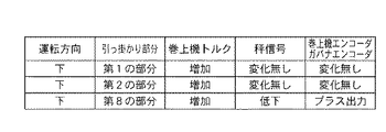
また、引っ掛かり部分の判定のために扱う信号をどのエレベータ機器から受けるかは、上記の例に限定されない。例えば、図7は図1の点検運転制御部18により引っ掛かり部分を判定するための判定基準の他の例を示す説明図である。図7の判定基準では、判定対象は図5の判定基準と同じであるが、扱う信号を増やすことで判定精度を向上させている。具体的には、巻上機トルク及び秤信号に加えて、巻上機エンコーダ2からの出力とガバナエンコーダ14からの出力との差を確認している。
In addition, the elevator device that receives the signal to be used for determining the hooked portion is not limited to the above example. For example, FIG. 7 is an explanatory diagram illustrating another example of a determination criterion for determining a hooked portion by the inspection
例えば、かご4を下方向へ点検運転する場合、第1又は第2の部分21,22に引っ掛かりが発生していると、釣合おもり5とともにかご4も動かなくなるので、巻上機エンコーダ2とガバナエンコーダ14との移動量の差はない。しかし、第8の部分28に引っ掛かりが発生していると、第4〜第6の部分24〜26の張力が緩むため、巻上機エンコーダ2の移動量に対し、ガバナエンコーダ14の移動量が小さくなり、出力の差がプラスとなる。このように、判定の項目を増やすことにより、判定の精度を向上させることができる。
For example, when the
実施の形態2.
次に、図8はこの発明の実施の形態2によるエレベータ装置を示す構成図、図9は図8のかご4を点検運転で上方へ走行させた状態を示す構成図である。点検運転制御部18は、巻上機トルクの信号及び秤信号に対して、かご位置に応じて定常的に変化する主索3や制御ケーブル(図示せず)などの正常時の重量を事前に記憶しておき、点検運転時にはそれによる影響を取り除くための補正演算を行う。また、点検運転制御部18は、補正演算後の出力値を所定の時間毎に平均化(又はローパスフィルタ処理)し、滑らかに変化する値とする。
Next, FIG. 8 is a block diagram showing an elevator apparatus according to
図10は図4に示した巻上機電流の出力に補正演算を行った結果を示すグラフ、図11は図10の演算結果に平均化処理を行った結果を示すグラフである。点検運転制御部18は、図11に示したような平均化処理後の巻上機電流について、予め設定されたかご移動距離(移動時間)毎に前確認点からの変化を求める。そして、予め設定された回数だけ、予め設定された変化量以上、同じ方向へ巻上機電流が変化したら、異常検出レベルを超えていなくても、引っ掛かりが発生していると判断し、かご4を停止させる。例えば、図11において、T1、T2、T3での検出レベルは、同じ方向に3回連続して増加しており、このような場合は、検出レベルの絶対値は小さいが、連続増加していることにより引っ掛かりと判断する。他の構成は、実施の形態1と同様である。
FIG. 10 is a graph showing a result of performing a correction calculation on the output of the hoisting machine current shown in FIG. 4, and FIG. 11 is a graph showing a result of performing an averaging process on the calculation result of FIG. The inspection
図12は図8の点検運転制御部18による引っ掛かり検出動作を示すフローチャートである。点検運転による検査が開始されると、まずかご位置及び運転方向を確認する(ステップS11)。そして、巻上機電流を検出し(ステップS12)、補正演算処理(ステップS13)及び平均化処理(ステップS14)を行う。そして、平均化後の巻上機電流が異常検出レベルを超えたかどうかを確認する(ステップS15)。
FIG. 12 is a flowchart showing a catch detection operation by the inspection
巻上機電流が異常検出レベルを超えていれば、引っ掛かりが発生していると判断し、かご4の走行を停止させる(ステップS16)。また、巻上機電流が異常検出レベルを超えていなければ、前確認点からのかご4の移動距離が設定量に達したかどうかを確認する(ステップS17)。設定量に達していなければ、巻上機電流検出、補正演算処理及び平均化処理を継続しながら、異常検出レベルとの比較を続ける。
If the hoisting machine current exceeds the abnormality detection level, it is determined that a catch has occurred, and the traveling of the
かご4が前確認点から設定量移動すると、前確認点からの巻上機電流の変化を求め、変化が異常であるかどうかを確認する(ステップS18)。そして、設定回数だけ、同じ方向へ設定量以上の変化が続いていれば、引っ掛かりが発生していると判断し、かご4の走行を停止させる。巻上機電流の変化が正常の範囲内であれば、上記の動作を繰り返す。また、引っ掛かり検出時の引っ掛かり部分の判定は、実施の形態1と同様に行うことができる。
When the
このようなエレベータ制御装置17によれば、調速機ロープ11のように強度が低く、引っ掛かりが発生したときの信号変動が小さい場合でも、引っ掛かりをより確実かつ早期に検出することができる。
また、補正演算処理を行うことにより、引っ掛かりによる信号変動をより確実に検出することができる。
さらに、平均化処理を行うことにより、一時的な信号変動による誤検出を防止し、引っ掛かりの検出精度を向上させることができる。
According to such an
Further, by performing the correction calculation process, it is possible to more reliably detect the signal fluctuation due to the catch.
Furthermore, by performing the averaging process, it is possible to prevent erroneous detection due to temporary signal fluctuations and improve the detection accuracy of the catch.
なお、補正演算処理や平均化処理は省略してもよく、信号処理を簡素化することができる。 Note that correction calculation processing and averaging processing may be omitted, and signal processing can be simplified.
実施の形態3.
次に、図13はこの発明の実施の形態3によるエレベータ装置を示す構成図、図14は図13のかご4を点検運転で上方へ走行させた状態を示す構成図である。図において、操作機構12は、第1及び第2のばね31,32を介して調速機ロープ11に接続されている。第1及び第2のばね31,32は、いたずら等によるかご4の揺れにより調速機10が過速度を誤検出するのを防止するために用いられている。操作機構12には、調速機ロープ11の張力変化により第1及び第2のばね31,32の変形量が設定量に達すると操作される第1及び第2の検出スイッチ33,34が設けられている。
Next, FIG. 13 is a block diagram showing an elevator apparatus according to
点検運転制御部18は、第1及び第2の検出スイッチ33,34からの信号に基づいて、引っ掛かりが発生していると判断するとともに、引っ掛かり部分が調速機ロープ11であると判定する。
Based on the signals from the first and second detection switches 33 and 34, the inspection
このように、調速機ロープ11とかご4との連結部に設けたスイッチ33,34からの信号により引っ掛かり部分の判定を行うこともできる。
In this way, the hooked portion can be determined by the signals from the
1 巻上機、2 巻上機エンコーダ(回転検出器)、3 主索(索状体)、4 かご、10 調速機、11 調速機ロープ(索状体)、14 ガバナエンコーダ(回転検出器)、15 秤装置、17 エレベータ制御装置、18 点検運転制御部。
1 hoisting machine, 2 hoisting machine encoder (rotation detector), 3 main rope (cord), 4 cage, 10 governor, 11 governor rope (cord), 14 governor encoder (rotation detection) Equipment), 15 scale device, 17 elevator control device, 18 inspection operation control unit.
Claims (7)
上記点検運転制御部は、点検運転中に、上記かごの走行方向と、巻上機のトルク信号と、上記かご内の負荷を検出する秤装置からの秤信号とに基づいて、上記かご及び上記車により分けられた上記主索及び上記調速機ロープの複数の部分のうちの所定の部分の引っ掛かりを検出し、検出結果を表示するための信号を出力することを特徴とするエレベータ制御装置。 Provided in an elevator apparatus comprising a car, a main rope for suspending the car, a governor rope connected to the car, and a plurality of vehicles around which the main rope or the governor rope is wound. In the elevator control device provided with an inspection operation control unit that automatically runs the above-mentioned car and checks whether there is an abnormality,
The inspection operation control unit, during the inspection operation, based on the traveling direction of the car, the torque signal of the hoisting machine, and the weighing signal from the weighing device that detects the load in the car, An elevator control device characterized by detecting a catch of a predetermined portion among a plurality of portions of the main rope and the governor rope divided by a vehicle and outputting a signal for displaying a detection result.
上記主索は、上記昇降路の上部に設けられた綱止め部に接続されている第1及び第2の端部を有しており、かつ、上記第1の端部側から順に、上記かご吊り車、上記第1の返し車、上記駆動シーブ、上記第2の返し車、及び上記釣合おもり吊り車に巻き掛けられており、The main rope has first and second end portions connected to a rope stopping portion provided at an upper portion of the hoistway, and the car is sequentially from the first end side. It is wound around a suspension car, the first return wheel, the drive sheave, the second return wheel, and the counterweight suspension car,
上記点検運転制御部は、上記かごを点検運転で下方へ走行させたとき、上記巻上機のトルク電流が増加し、かつ、上記秤信号が変化しない場合に、上記主索の上記第2の端部から上記釣合おもり吊り車までの部分、又は上記主索の上記釣合おもり吊り車から上記第2の返し車までの部分に引っ掛かりが発生したと判定することを特徴とする請求項1記載のエレベータ制御装置。The inspection operation control unit causes the second current of the main rope to be increased when the torque current of the hoisting machine increases and the scale signal does not change when the car travels downward in the inspection operation. 2. It is determined that a portion of the main rope from the counterweight suspension vehicle or a portion of the main rope from the counterweight suspension vehicle to the second return wheel has been caught. The elevator control device described.
上記調速機ロープは、上記調速機シーブ及び上記張り車に巻き掛けられており、The governor rope is wound around the governor sheave and the tension wheel,
上記点検運転制御部は、上記かごを点検運転で下方へ走行させたとき、上記秤装置で検出される負荷が低下し、かつ、上記巻上機のトルクが大きくなった場合に、上記調速機ロープの上記かごとの連結部と上記張り車との間の部分に引っ掛かりが発生したと判定することを特徴とする請求項1記載のエレベータ制御装置。The inspection operation control unit is configured to control the speed control when the load detected by the scale device decreases and the hoisting machine torque increases when the car travels downward in the inspection operation. 2. The elevator control device according to claim 1, wherein it is determined that a portion of the machine rope between the connecting portion of the cage and the tensioning wheel is caught.
Priority Applications (1)
| Application Number | Priority Date | Filing Date | Title |
|---|---|---|---|
| JP2005346219A JP4828215B2 (en) | 2005-11-30 | 2005-11-30 | Elevator control device |
Applications Claiming Priority (1)
| Application Number | Priority Date | Filing Date | Title |
|---|---|---|---|
| JP2005346219A JP4828215B2 (en) | 2005-11-30 | 2005-11-30 | Elevator control device |
Publications (3)
| Publication Number | Publication Date |
|---|---|
| JP2007145589A JP2007145589A (en) | 2007-06-14 |
| JP2007145589A5 JP2007145589A5 (en) | 2010-05-20 |
| JP4828215B2 true JP4828215B2 (en) | 2011-11-30 |
Family
ID=38207456
Family Applications (1)
| Application Number | Title | Priority Date | Filing Date |
|---|---|---|---|
| JP2005346219A Active JP4828215B2 (en) | 2005-11-30 | 2005-11-30 | Elevator control device |
Country Status (1)
| Country | Link |
|---|---|
| JP (1) | JP4828215B2 (en) |
Families Citing this family (6)
| Publication number | Priority date | Publication date | Assignee | Title |
|---|---|---|---|---|
| JP5120811B2 (en) * | 2008-03-18 | 2013-01-16 | 東芝エレベータ株式会社 | Elevator control device |
| JP5223528B2 (en) * | 2008-08-04 | 2013-06-26 | フジテック株式会社 | Rail release detector |
| JP5431064B2 (en) * | 2009-08-07 | 2014-03-05 | 株式会社日立製作所 | Elevator control device |
| JP2013252977A (en) * | 2013-09-25 | 2013-12-19 | Hitachi Ltd | Elevator system |
| WO2019215844A1 (en) * | 2018-05-09 | 2019-11-14 | 三菱電機株式会社 | Elevator device and emergency stop inspection device testing method |
| JP6991356B2 (en) * | 2018-10-03 | 2022-01-12 | 三菱電機株式会社 | Elevator controller |
Family Cites Families (6)
| Publication number | Priority date | Publication date | Assignee | Title |
|---|---|---|---|---|
| JPS6169678A (en) * | 1984-09-07 | 1986-04-10 | 株式会社日立製作所 | Elevator device |
| JPS63100473A (en) * | 1985-12-27 | 1988-05-02 | Ricoh Co Ltd | Control method for electrophotographic copying machine |
| JPH0684233B2 (en) * | 1986-03-05 | 1994-10-26 | 株式会社日立製作所 | Elevator device and operation control method thereof |
| JP3375454B2 (en) * | 1995-05-01 | 2003-02-10 | 三菱電機ビルテクノサービス株式会社 | Elevator seismic control operation device |
| JPH10120327A (en) * | 1996-10-23 | 1998-05-12 | Toshiba Elevator Technos Kk | Abnormality detection device for elevator governor rope |
| JPH1179589A (en) * | 1997-09-11 | 1999-03-23 | Mitsubishi Denki Bill Techno Service Kk | Abnormality detecting device of main rope of elevator |
-
2005
- 2005-11-30 JP JP2005346219A patent/JP4828215B2/en active Active
Also Published As
| Publication number | Publication date |
|---|---|
| JP2007145589A (en) | 2007-06-14 |
Similar Documents
| Publication | Publication Date | Title |
|---|---|---|
| JP4907097B2 (en) | Elevator equipment | |
| JP4849397B2 (en) | Elevator abnormality detection device | |
| JP5459387B2 (en) | Elevator equipment | |
| JP6049902B2 (en) | Elevator diagnostic equipment | |
| JP4828215B2 (en) | Elevator control device | |
| JP4994633B2 (en) | Elevator automatic inspection device | |
| JP6601559B2 (en) | Break detection device | |
| JP4675390B2 (en) | Elevator earthquake recovery equipment | |
| JP5224933B2 (en) | Elevator restoration operation method and apparatus | |
| JP4850477B2 (en) | Elevator apparatus automatic inspection method and elevator control apparatus | |
| WO2019030888A1 (en) | Break detection device | |
| JP6218706B2 (en) | Elevator control device and elevator control method | |
| JP5079351B2 (en) | Elevator equipment | |
| JP5026078B2 (en) | Elevator equipment | |
| JP6480840B2 (en) | Elevator and control method of elevator | |
| JP4849395B2 (en) | Elevator abnormality detection device | |
| JP4858108B2 (en) | Elevator apparatus and elevator control method | |
| WO2021144932A1 (en) | Elevator determination device | |
| EP3068720B1 (en) | Elevator system for detection of stuck elevator car or counterweight | |
| JP5431064B2 (en) | Elevator control device | |
| JP5979971B2 (en) | Elevator control device | |
| JP2007331902A (en) | Control device of elevator | |
| JP2013252977A (en) | Elevator system | |
| JPWO2020026384A1 (en) | Elevator equipment | |
| JP5431281B2 (en) | Elevator suspension means abnormal position detection device |
Legal Events
| Date | Code | Title | Description |
|---|---|---|---|
| A521 | Request for written amendment filed |
Free format text: JAPANESE INTERMEDIATE CODE: A523 Effective date: 20070727 |
|
| A621 | Written request for application examination |
Free format text: JAPANESE INTERMEDIATE CODE: A621 Effective date: 20080421 |
|
| A521 | Request for written amendment filed |
Free format text: JAPANESE INTERMEDIATE CODE: A523 Effective date: 20100405 |
|
| A977 | Report on retrieval |
Free format text: JAPANESE INTERMEDIATE CODE: A971007 Effective date: 20110202 |
|
| A131 | Notification of reasons for refusal |
Free format text: JAPANESE INTERMEDIATE CODE: A131 Effective date: 20110208 |
|
| TRDD | Decision of grant or rejection written | ||
| A01 | Written decision to grant a patent or to grant a registration (utility model) |
Free format text: JAPANESE INTERMEDIATE CODE: A01 Effective date: 20110913 |
|
| A01 | Written decision to grant a patent or to grant a registration (utility model) |
Free format text: JAPANESE INTERMEDIATE CODE: A01 |
|
| A61 | First payment of annual fees (during grant procedure) |
Free format text: JAPANESE INTERMEDIATE CODE: A61 Effective date: 20110914 |
|
| FPAY | Renewal fee payment (event date is renewal date of database) |
Free format text: PAYMENT UNTIL: 20140922 Year of fee payment: 3 |
|
| R150 | Certificate of patent or registration of utility model |
Ref document number: 4828215 Country of ref document: JP Free format text: JAPANESE INTERMEDIATE CODE: R150 Free format text: JAPANESE INTERMEDIATE CODE: R150 |
|
| R250 | Receipt of annual fees |
Free format text: JAPANESE INTERMEDIATE CODE: R250 |
|
| R250 | Receipt of annual fees |
Free format text: JAPANESE INTERMEDIATE CODE: R250 |
|
| R250 | Receipt of annual fees |
Free format text: JAPANESE INTERMEDIATE CODE: R250 |
|
| R250 | Receipt of annual fees |
Free format text: JAPANESE INTERMEDIATE CODE: R250 |
|
| R250 | Receipt of annual fees |
Free format text: JAPANESE INTERMEDIATE CODE: R250 |
|
| S533 | Written request for registration of change of name |
Free format text: JAPANESE INTERMEDIATE CODE: R313533 |
|
| R350 | Written notification of registration of transfer |
Free format text: JAPANESE INTERMEDIATE CODE: R350 |
|
| R250 | Receipt of annual fees |
Free format text: JAPANESE INTERMEDIATE CODE: R250 |