JP4823874B2 - Electric lock - Google Patents

Electric lock Download PDF

Info

Publication number
JP4823874B2
JP4823874B2 JP2006320464A JP2006320464A JP4823874B2 JP 4823874 B2 JP4823874 B2 JP 4823874B2 JP 2006320464 A JP2006320464 A JP 2006320464A JP 2006320464 A JP2006320464 A JP 2006320464A JP 4823874 B2 JP4823874 B2 JP 4823874B2
Authority
JP
Japan
Prior art keywords
latch
stopper
state
plate
latch bolt
Prior art date
Legal status (The legal status is an assumption and is not a legal conclusion. Google has not performed a legal analysis and makes no representation as to the accuracy of the status listed.)
Active
Application number
JP2006320464A
Other languages
Japanese (ja)
Other versions
JP2008133656A (en
Inventor
三徳 三宅
Current Assignee (The listed assignees may be inaccurate. Google has not performed a legal analysis and makes no representation or warranty as to the accuracy of the list.)
Goal Co Ltd
Original Assignee
Goal Co Ltd
Priority date (The priority date is an assumption and is not a legal conclusion. Google has not performed a legal analysis and makes no representation as to the accuracy of the date listed.)
Filing date
Publication date
Application filed by Goal Co Ltd filed Critical Goal Co Ltd
Priority to JP2006320464A priority Critical patent/JP4823874B2/en
Publication of JP2008133656A publication Critical patent/JP2008133656A/en
Application granted granted Critical
Publication of JP4823874B2 publication Critical patent/JP4823874B2/en
Active legal-status Critical Current
Anticipated expiration legal-status Critical

Links

Images

Description

本発明は、電気的に施錠または解錠することが可能な電気錠に関するものであり、特に施錠状態において電気的に解錠することなく取手の操作のみで解錠および開扉が可能とすることができる電気錠に関するものである。   The present invention relates to an electric lock that can be electrically locked or unlocked, and in particular, can be unlocked and opened only by a handle operation without being electrically unlocked in a locked state. It relates to an electric lock that can be used.

従来、ソレノイドを使用して施解錠する電気錠は、通常、閉扉した状態で自動的に施錠される。これにより、施錠し忘れることがなく、防犯性に優れている。
このような電気錠は、ビルの通用口やホテルの客室などで使用されている。
特開平8−120990号公報
Conventionally, an electric lock that is locked and unlocked using a solenoid is normally automatically locked in a closed state. Thereby, it does not forget locking and is excellent in crime prevention.
Such electric locks are used in building entrances and hotel rooms.
JP-A-8-120990

しかしながら、例えば、ホテルの客室などでは、防犯性の問題から閉扉すると自動的に施錠されるようにしてあり、施錠された状態において室外側からはキーなどにより解錠する必要があるが、室内側からは解錠操作なしに取手の操作のみで解錠および開扉ができるほうが好ましい。
このような事情から、アンチパニック式の電気錠が提案されている(特許文献1)。
ところが、特許文献1に記載の発明は、異なる構成の錠前には対応できなかった。
However, for example, hotel rooms are automatically locked when they are closed due to security problems, and need to be unlocked from the outside with a key or the like in the locked state. It is preferable that the door can be unlocked and opened only by the handle operation without the unlocking operation.
Under such circumstances, an anti-panic electric lock has been proposed (Patent Document 1).
However, the invention described in Patent Document 1 cannot cope with locks having different configurations.

本発明が解決しようとする課題は、特許文献1とは異なる構成の錠前であって、施錠状態において電気的に解錠することなく取手の操作のみで解錠可能とすることができる電気錠を提供することにある。   The problem to be solved by the present invention is a lock having a configuration different from that of Patent Document 1, and an electric lock that can be unlocked only by a handle operation without being electrically unlocked in a locked state. It is to provide.

本発明は、前記課題を解決するためになされたものであり、請求項1に記載の発明は、錠ケースに進退可能に設けられるラッチボルトと、このラッチボルトを突出させた状態で後退規制可能なストッパーと、取手の操作に基づき回動してラッチボルトを後退可能なラッチハブ板と、上方位置ではラッチボルトを規制したストッパーを規制解除不能とする一方、下方位置では前記ラッチハブ板により回動してストッパーを規制解除方向へ回動させる解錠部材とを備えることを特徴とする電気錠である。   SUMMARY OF THE INVENTION The present invention has been made to solve the above-mentioned problems, and the invention according to claim 1 is capable of regulating the backward movement in a state in which the latch bolt is provided in the lock case so as to be able to advance and retract, and the latch bolt projects. And a latch hub plate that can be rotated based on the operation of the handle to retract the latch bolt, and the stopper that restricts the latch bolt at the upper position cannot be unregulated, while it is rotated by the latch hub plate at the lower position. And an unlocking member for rotating the stopper in the restriction release direction.

請求項2に記載の発明は、錠ケースに進退可能に設けられるラッチボルトと、錠ケースに枢支されてラッチボルトを突出させた状態で後退不能に係止するよう付勢されるストッパーと、取手の操作に基づき回動してラッチボルトを後退可能なラッチハブ板と、支軸まわりに回動可能で、その支軸が錠ケースに対して上下動可能に保持された解錠部材と、前記支軸を上方位置または下方位置に位置決めする切替部材とを備え、前記切替部材により前記支軸が上方位置に配置された状態では、ラッチボルトを規制したストッパーを規制解除不能とする一方、前記切替部材により前記支軸が下方位置に配置された状態では、取手の操作により回動する前記ラッチハブ板によって前記解錠部材が回動して、前記ストッパーを付勢力に対抗して回動させることを特徴とする電気錠である。   The invention according to claim 2 is a latch bolt that is provided in the lock case so as to be able to advance and retract, and a stopper that is pivotally supported by the lock case and urged so as to be locked so as not to retract in a state in which the latch bolt protrudes. A latch hub plate that can be rotated based on an operation of the handle to retract the latch bolt; an unlocking member that is rotatable about a support shaft, and that the support shaft is held to be movable up and down with respect to the lock case; A switching member that positions the support shaft at an upper position or a lower position, and when the support shaft is disposed at the upper position by the switching member, the stopper that restricts the latch bolt is disabled from being released. In a state where the support shaft is disposed at a lower position by the member, the unlocking member is rotated by the latch hub plate that is rotated by a handle operation, and the stopper is rotated against the urging force. It is an electric lock according to claim.

請求項3に記載の発明は、前記切替部材は、錠ケースに枢支されており、切替部材の回動が規制されることで前記支軸の位置決めがなされることを特徴とする請求項2に記載の電気錠である。   The invention according to claim 3 is characterized in that the switching member is pivotally supported by a lock case, and the pivot is positioned by restricting the rotation of the switching member. It is an electric lock as described in.

請求項4に記載の発明は、前記切替部材は、錠ケースに取り付けられるカバーに形成された穴に差し込まれることで回動が規制されることを特徴とする請求項3に記載の電気錠である。   According to a fourth aspect of the present invention, in the electric lock according to the third aspect, the rotation of the switching member is restricted by being inserted into a hole formed in a cover attached to the lock case. is there.

さらに、請求項5に記載の発明は、ソレノイドにより枢軸まわりに回動し、その枢軸が錠ケースに対して上下動可能に保持されたテコ板と、このテコ板と前記ストッパーとを連結する第一リンク材と、前記枢軸を上方位置または下方位置に位置決めする切替機構とをさらに備え、前記切替機構により前記枢軸が上方位置に配置された状態では、ソレノイドの作動により前記テコ板が前記第一リンク材を介して前記ストッパーを付勢力に対抗して回動させてラッチボルトの後退を可能とする一方、前記切替機構により前記枢軸が下方位置に配置された状態では、前記テコ板が前記ストッパーを付勢力に対抗して回動させてラッチボルトの後退を可能とし、ソレノイドの作動により前記ストッパーが前記ラッチボルトの後退を規制することを特徴とする請求項1から請求項4までのいずれかに記載の電気錠である。   Furthermore, the invention described in claim 5 is a first mechanism for connecting a lever plate, which is pivoted around a pivot axis by a solenoid, the pivot axis being held so as to be vertically movable with respect to the lock case, and the lever plate and the stopper. And a switching mechanism for positioning the pivot at an upper position or a lower position. When the pivot is positioned at the upper position by the switching mechanism, the lever plate is moved to the first position by the operation of a solenoid. While the stopper is rotated against the urging force via the link member to allow the latch bolt to move backward, the lever plate is disposed at the lower position by the switching mechanism. The latch bolt can be retracted by rotating it against the urging force, and the stopper regulates the retract of the latch bolt by the operation of a solenoid. An electric lock according to any one of claims 1 to 4.

本発明の電気錠によれば、施錠状態において電気的にまたは手動で解錠することなく取手の操作のみで解錠可能とすることができる。   According to the electric lock of the present invention, it can be unlocked only by a handle operation without being unlocked electrically or manually in the locked state.

以下、本発明の電気錠について、図面に基づき更に詳細に説明する。
ここでは、本発明の電気錠が例えばビルの通用口に適用される場合について説明する。
なお、以下の説明においては、扉が閉鎖した状態において室内外方向を前後方向とし、扉の幅方向を左右方向とする。
Hereinafter, the electric lock of the present invention will be described in more detail based on the drawings.
Here, the case where the electric lock of the present invention is applied to, for example, a building entrance will be described.
In the following description, when the door is closed, the indoor / outdoor direction is the front / rear direction, and the width direction of the door is the left / right direction.

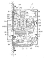
図1および図2は、本発明の電気錠の一実施例を示す図であり、図1は本実施例の電気錠の扉への取付状態を室外側から見た斜視図であり、図2は本実施例の電気錠の縦断面図であり、通電時解錠タイプにセットされ施錠された状態を示す図である。なお、図2では、第二切替機構が取り外されている。
また、図3は、図2の主要部を示す図であり、施錠機構などを示している。
さらに、図4は、本実施例の電気錠を戸先側から見た図であり、(a)はフロント板が取り外され、フロント裏板が露出した状態を示しており、(b)はさらにカバーが取り外された状態を示している。
1 and 2 are views showing an embodiment of the electric lock of the present invention, and FIG. 1 is a perspective view of the electric lock according to the present embodiment attached to a door as seen from the outdoor side. These are the longitudinal cross-sectional views of the electric lock of a present Example, and are the figures which show the state set to the unlocking type at the time of electricity supply and locked. In FIG. 2, the second switching mechanism is removed.
FIG. 3 is a diagram showing a main part of FIG. 2 and shows a locking mechanism and the like.
Further, FIG. 4 is a view of the electric lock of the present embodiment as viewed from the door end side, where (a) shows a state where the front plate is removed and the front back plate is exposed, and (b) further shows The cover is removed.

本実施例の電気錠は、後述するソレノイドに設けられたプランジャを進退させることで、施解錠を行うことができる。
そして、本実施例の電気錠は、通電時解錠タイプ(ソレノイドに通電している間は解錠状態)、または通電時施錠タイプ(ソレノイドに通電している間は施錠状態)のいずれかのタイプに切り替え可能な構成とされる。
The electric lock of the present embodiment can be locked and unlocked by advancing and retracting a plunger provided on a solenoid described later.
The electric lock of this embodiment is either an unlocked type when energized (unlocked while the solenoid is energized) or an unlocked type when energized (locked while the solenoid is energized). It can be switched to type.

また、本実施例の電気錠1は、通電時解錠タイプにセットされ施錠された状態、または通電時施錠タイプにセットされ施錠された状態において、ソレノイドに通電したり、ソレノイドを非通電とすることなく、取手の操作のみで解錠可能ないわゆるアンチパニック機能を有しており、このアンチパニック機能を働かせるか否かを切り替えることが可能とされる。   Further, the electric lock 1 of the present embodiment energizes the solenoid or deenergizes the solenoid in the unlocked type when energized and locked, or in the locked state when energized and locked. Therefore, it has a so-called anti-panic function that can be unlocked only by a handle operation, and it is possible to switch whether or not to activate this anti-panic function.

以下においては、まず、本実施例の電気錠1が、通電時解錠タイプまたは通電時施錠タイプに切り替え可能な構成について説明する。
最初に、本実施例の電気錠1が、図2に示すように、通電時解錠タイプにセットされ、施錠された状態について説明する。
In the following, first, a description will be given of a configuration in which the electric lock 1 of the present embodiment can be switched to the unlocking type when energized or the locking type when energized.
Initially, the electric lock 1 of a present Example is set to the unlocking type at the time of energization as shown in FIG. 2, and the locked state is demonstrated.

本実施例の電気錠1は、扉2の戸先側端部に内蔵される錠ケース5と、この錠ケース5に設けられ、錠ケース5の戸先側端面13から出没可能なラッチボルト6と、このラッチボルト6を取手4の操作に応じて錠ケース5の戸先側端面13において出没させるラッチ後退操作機構7と、ラッチボルト6を所定の突出位置に規制する施錠機構8と、この施錠機構8にリンク機構9を介して接続されるソレノイド10とを主要部に備える。
また、本実施例の電気錠1は、通電時解錠タイプまたは通電時施錠タイプのいずれかに切り替えるための第一切替機構11も備える。
The electric lock 1 of the present embodiment includes a lock case 5 built in the door end side end portion of the door 2 and a latch bolt 6 provided in the lock case 5 and capable of protruding and retracting from the door end side end surface 13 of the lock case 5. A latch retraction operation mechanism 7 that causes the latch bolt 6 to protrude and retract on the door end side end surface 13 of the lock case 5 according to the operation of the handle 4, a locking mechanism 8 that restricts the latch bolt 6 to a predetermined protruding position, The main part is provided with a solenoid 10 connected to the locking mechanism 8 via a link mechanism 9.
Moreover, the electric lock 1 of a present Example is also provided with the 1st switching mechanism 11 for switching to either an energization unlocking type or an energization locking type.

本実施例の電気錠1が取り付けられる扉2は、開き戸形式とされ、例えば室外側へ開く外開き扉とされる。
具体的には、扉2は、扉枠(不図示)の一側端部に、ヒンジを介して回動可能に取り付けられている。そして、扉2に設けられた取手4を操作することで、ラッチボルト6が進退して扉2の開閉を行うことができる。この取手4は、扉2の室外側と室内側の双方に設けられており、本実施例ではノブ型の取手とされる。
また、本実施例の電気錠1には、扉2の室外側にシリンダー装置12が接続され、扉2の室内側にサムターン装置(不図示)が接続されている。
The door 2 to which the electric lock 1 of the present embodiment is attached is a hinged door type, for example, an exterior door that opens outward.
Specifically, the door 2 is rotatably attached to one end of a door frame (not shown) via a hinge. And by operating the handle 4 provided in the door 2, the latch bolt 6 can be advanced and retracted, and the door 2 can be opened and closed. The handle 4 is provided on both the outdoor side and the indoor side of the door 2, and is a knob-type handle in this embodiment.
Moreover, the cylinder device 12 is connected to the outdoor side of the door 2 and the thumb turn device (not shown) is connected to the indoor side of the door 2 in the electric lock 1 of the present embodiment.

錠ケース5は、矩形箱状とされる。
本実施例の錠ケース5は、室外側(基端側)へ開口するケース本体5Aと、その開口を閉じるようケース本体5Aに重ね合わされてネジで固定される矩形板状の蓋5Bとを備える。
The lock case 5 has a rectangular box shape.
The lock case 5 of this embodiment includes a case main body 5A that opens to the outdoor side (base end side), and a rectangular plate-shaped lid 5B that is overlaid on the case main body 5A and is fixed with screws so as to close the opening. .

錠ケース5は、扉2の戸先側端部の上下方向略中央部に取り付けられる。
具体的には、図2に示すように、錠ケース5の左側壁面(戸先側端面)13には、矩形板状のフロント裏板14が重ね合わされる。そして、図2に示すように、錠ケース5が扉2に埋め込まれると共に、フロント裏板14を介して扉2の戸先側端部に取付ネジ15で錠ケース5が扉2に固定される。
そして、フロント板16が扉2の戸先側端面に重ね合わされてネジ17でフロント裏板14に固定される。
The lock case 5 is attached to a substantially central portion in the vertical direction of the door end side end portion of the door 2.
Specifically, as shown in FIG. 2, a rectangular plate-like front back plate 14 is superimposed on the left wall surface (door end side end surface) 13 of the lock case 5. Then, as shown in FIG. 2, the lock case 5 is embedded in the door 2, and the lock case 5 is fixed to the door 2 with a mounting screw 15 at the door end side end portion of the door 2 through the front back plate 14. .
Then, the front plate 16 is superimposed on the door end side end surface of the door 2 and fixed to the front back plate 14 with screws 17.

フロント裏板14およびフロント板16には、後述するラッチ頭部26が通される貫通穴14a,16aがそれぞれ形成されていると共に、トリガー頭部129が通される貫通穴14b,16bがそれぞれ形成されている。
また、図3および図4に示すように、錠ケース5の左側壁面13には、後述する第一切替部材95の操作部98および第二切替部材204の操作部219が差し込まれる3つの穴221,18,222が左右に離隔して形成されている。各穴221,18,222は、上下方向に細長い穴とされる。
さらに、フロント裏板14には、錠ケース5の穴221,18,222に対応した位置に矩形状の開口部19が形成されており、この開口部19には、矩形板状のカバー20がはめ込まれてネジ21で錠ケース5に固定されている。
The front back plate 14 and the front plate 16 are formed with through holes 14a and 16a through which a latch head 26 described later is passed, and through holes 14b and 16b through which the trigger head 129 is passed. Has been.
As shown in FIGS. 3 and 4, three holes 221 into which an operation portion 98 of the first switching member 95 and an operation portion 219 of the second switching member 204 described later are inserted into the left wall surface 13 of the lock case 5. , 18, 222 are spaced apart from each other on the left and right. Each of the holes 221, 18, and 222 is an elongated hole in the vertical direction.
Further, a rectangular opening 19 is formed in the front back plate 14 at a position corresponding to the holes 221, 18, and 222 of the lock case 5, and a rectangular plate-shaped cover 20 is formed in the opening 19. It is fitted and fixed to the lock case 5 with a screw 21.

図4に示すように、カバー20には、上側に矩形状の貫通穴223,22,225が3つ、左右方向に離隔して形成されており、各貫通穴223,22,225の下方に矩形状の貫通穴224,23,226がそれぞれ形成されている。
つまり、カバー20には、上下に離隔した一対の矩形状の貫通穴(223,224)(22,23)(225,226)が、左右に離隔して3つ形成されている。
カバー20の各貫通穴22,23,223,224,225,226は、第一切替部材95の操作部98および第二切替部材204の操作部219に対応した大きさとされる。また、このカバー20は、フロント裏板14にフロント板16が重ね合わされることで、外部から視認されることはない。
As shown in FIG. 4, the cover 20 is formed with three rectangular through holes 223, 22, 225 on the upper side, spaced apart in the left-right direction, and below the through holes 223, 22, 225. Rectangular through holes 224, 23, and 226 are formed, respectively.
That is, the cover 20 is formed with three pairs of rectangular through holes (223, 224) (22, 23) (225, 226) spaced apart in the vertical direction.
The through holes 22, 23, 223, 224, 225, and 226 of the cover 20 are sized corresponding to the operation part 98 of the first switching member 95 and the operation part 219 of the second switching member 204. In addition, the cover 20 is not visually recognized from the outside because the front plate 16 is superimposed on the front back plate 14.

ラッチボルト6は、左右方向に移動可能に錠ケース5内に設けられる。
本実施例のラッチボルト6は、錠ケース5の戸先側端面13から突出して扉枠(不図示)の戸先側縦枠24に設けられた受25の受穴25aに突入するラッチ頭部26と、このラッチ頭部26に設けられる丸棒状のラッチ軸部27と、このラッチ軸部27が挿通されるラッチガイド板28とを有する。
The latch bolt 6 is provided in the lock case 5 so as to be movable in the left-right direction.
The latch bolt 6 of the present embodiment protrudes from the door end side end face 13 of the lock case 5 and enters the receiving hole 25a of the receiver 25 provided in the door end side vertical frame 24 of the door frame (not shown). 26, a round bar-shaped latch shaft portion 27 provided on the latch head portion 26, and a latch guide plate 28 through which the latch shaft portion 27 is inserted.

ラッチ頭部26は、矩形状のブロック体とされ、その左端部は、室内側(先端側)へ行くに従って右側へ傾斜する傾斜面6aが形成され、中央部は室内側も直線部6bが形成されている。
また、ラッチ頭部26の右端部には、右側へ開口する筒状部29が一体に形成されており、この筒状部29にラッチ軸部27の左端部がはめ込まれてラッチ頭部26にラッチ軸部27が固定されている。
The latch head portion 26 is a rectangular block body, and the left end portion thereof is formed with an inclined surface 6a that is inclined to the right side toward the indoor side (front end side), and the central portion is also formed with a linear portion 6b on the indoor side. Has been.
A cylindrical portion 29 that opens to the right is integrally formed at the right end portion of the latch head portion 26, and the left end portion of the latch shaft portion 27 is fitted into the cylindrical portion 29, so that the latch head portion 26 is fitted. The latch shaft portion 27 is fixed.

ラッチ軸部27は、その軸方向が左右方向に沿うように配置されて、錠ケース5の室内側壁面30に固定された支持部材31に挿通されている。
支持部材31は、板材を屈曲して形成された右側へ開口するコ字形材とされ、その中央片32には左右方向に沿って貫通穴が形成されている。
そして、この支持部材31の貫通穴にラッチ軸部27が挿通されて、ラッチ軸部27が支持部材31に左右方向に移動可能に保持されている。
The latch shaft portion 27 is disposed so that its axial direction is along the left-right direction, and is inserted through a support member 31 fixed to the indoor side wall surface 30 of the lock case 5.
The support member 31 is a U-shaped material that is formed by bending a plate and opens to the right, and a through hole is formed in the center piece 32 along the left-right direction.
The latch shaft portion 27 is inserted into the through hole of the support member 31, and the latch shaft portion 27 is held by the support member 31 so as to be movable in the left-right direction.

ラッチガイド板28は、板材を屈曲して形成された上方へ開口する略コ字形材とされ、その左右端片33,34間を架け渡すようにラッチ軸部27が挿通されて、ラッチガイド板28はラッチ軸部27に固定されている。   The latch guide plate 28 is a substantially U-shaped material that is formed by bending a plate material and opens upward, and the latch shaft portion 27 is inserted so as to bridge between the left and right end pieces 33, 34. 28 is fixed to the latch shaft 27.

ラッチガイド板28の左端片33は、ラッチ頭部26の筒状部29に当接すると共に、その上端部が筒状部29の周側面に沿って左側へ屈曲され、さらにラッチ頭部26の右端面に沿って上方へ屈曲されて、略L字形の段部35が形成されている。
また、ラッチガイド板28の右端片34には、先端側および基端側へ突出して矩形状の突部36が一体に形成されている。
さらに、ラッチガイド板28の中央片の左右方向略中央部には、下方へ突出して矩形状の係止部37が形成されている。
そして、ラッチ軸部27にラッチガイド板28が取り付けられた状態において、ラッチ軸部27の右端部38は、ラッチガイド板28の右端片34から右側へ延出している。
このような構成のラッチ頭部26、ラッチ軸部27およびラッチガイド板28は左右方向に一体に移動する。
The left end piece 33 of the latch guide plate 28 is in contact with the cylindrical portion 29 of the latch head portion 26, and the upper end portion thereof is bent to the left along the peripheral side surface of the cylindrical portion 29. A substantially L-shaped step 35 is formed by bending upward along the surface.
Further, a rectangular protrusion 36 is integrally formed on the right end piece 34 of the latch guide plate 28 so as to protrude toward the distal end side and the proximal end side.
Further, a rectangular locking portion 37 is formed at a substantially central portion in the left-right direction of the central piece of the latch guide plate 28 so as to protrude downward.
In a state where the latch guide plate 28 is attached to the latch shaft portion 27, the right end portion 38 of the latch shaft portion 27 extends from the right end piece 34 of the latch guide plate 28 to the right side.
The latch head 26, the latch shaft 27, and the latch guide plate 28 having such a configuration move integrally in the left-right direction.

また、ラッチ軸部27にラッチガイド板28が取り付けられた状態において、支持部材31は、ラッチガイド板28の左右端片33,34間に配置されている。
さらに、ラッチ軸部27には、コイルバネ39が挿通されており、バネ39の一端部がラッチガイド板28の左端片33に当接する一方、他端部が支持部材31の中央片32に当接している。
これによりラッチボルト6は、戸先側へ付勢されており、ラッチ頭部26はフロント裏板14およびフロント板16の穴14a,16aを介して戸先側へ突出可能とされている。
そして、図2に示すように、閉扉され施錠された状態においては、ラッチ頭部26は扉枠に設けられた受25に突入している。
Further, in a state where the latch guide plate 28 is attached to the latch shaft portion 27, the support member 31 is disposed between the left and right end pieces 33 and 34 of the latch guide plate 28.
Further, a coil spring 39 is inserted into the latch shaft 27, and one end of the spring 39 abuts on the left end piece 33 of the latch guide plate 28, while the other end abuts on the center piece 32 of the support member 31. ing.
As a result, the latch bolt 6 is biased toward the door-end side, and the latch head 26 can protrude toward the door-end side through the holes 14 a and 16 a of the front back plate 14 and the front plate 16.
As shown in FIG. 2, in a state where the door is closed and locked, the latch head 26 enters a receiver 25 provided on the door frame.

ラッチボルト6は、取手4の操作により、ラッチ後退操作機構7を介して後退させられる。
なお、取手4の先端部には、断面矩形状の軸部(不図示)が一体に設けられている。
The latch bolt 6 is retracted through the latch retracting operation mechanism 7 by the operation of the handle 4.
A shaft portion (not shown) having a rectangular cross section is integrally provided at the distal end portion of the handle 4.

ラッチ後退操作機構7は、室外側の取手4の操作をラッチボルト6に伝達する室外側ラッチ後退操作機構7Aと、室内側の取手の操作をラッチボルト6に伝達する室内側ラッチ後退操作機構7Bとを有し、前後方向に隣接して一対に設けられている。
室外側ラッチ後退操作機構7Aと室内側ラッチ後退操作機構7Bは同様の構成であり、以下においては室外側ラッチ後退操作機構7Aについて説明する。
The latch retracting operation mechanism 7 includes an outdoor latch retracting operation mechanism 7A for transmitting the operation of the outdoor handle 4 to the latch bolt 6 and an indoor latch retracting operation mechanism 7B for transmitting the operation of the indoor handle to the latch bolt 6. And are provided in a pair adjacent to each other in the front-rear direction.
The outdoor latch retracting mechanism 7A and the indoor latch retracting mechanism 7B have the same configuration, and the outdoor latch retracting mechanism 7A will be described below.

ラッチ後退操作機構7は、取手4の軸部がはめ込まれ、取手4の回転操作に伴い回動するラッチハブ40と、このラッチハブ40に回動可能に設けられるラッチハブ板41と、このラッチハブ板41に連結されるハブテコ42と、このハブテコ42に連結され、左右方向に移動可能に設けられるスライド部材43とを有する。   The latch retraction operation mechanism 7 includes a latch hub 40 that is fitted with the shaft portion of the handle 4 and rotates in accordance with the rotation operation of the handle 4, a latch hub plate 41 that is rotatably provided on the latch hub 40, and a latch hub plate 41. A hub lever 42 to be connected and a slide member 43 connected to the hub lever 42 and provided to be movable in the left-right direction are provided.

ラッチハブ40は、軸方向が前後方向に沿った円柱形状とされ、この先端部から左側へ行くに従って上下方向に拡幅する扇形板状の係合片44とが一体に形成されている。
また、ラッチハブ40には、その中央部に前後方向に沿って略矩形状の貫通穴45が形成されている。
The latch hub 40 has a cylindrical shape whose axial direction extends in the front-rear direction, and is integrally formed with a fan-shaped plate-like engagement piece 44 that expands in the vertical direction as it goes to the left from the tip.
Further, the latch hub 40 is formed with a substantially rectangular through hole 45 at the center thereof along the front-rear direction.

ラッチハブ板41は、ラッチハブ40が回動可能にはめ込まれる円形の貫通穴46が形成された矩形板状の一片47と、この一片47から上方へ延出する矩形状の他片48とが一体に設けられた板状体とされる。
ラッチハブ板41の一片47には、略U字状に切り欠かれて外方へ開口する凹部49が形成されている。
また、ラッチハブ板41の一片47には、先端側へ突出して円柱状のピン50が一体に設けられている。
さらに、ラッチハブ板41の他片48の上端部は、略三角形状に形成されている。
The latch hub plate 41 has a rectangular plate-like piece 47 formed with a circular through hole 46 into which the latch hub 40 is rotatably fitted, and a rectangular other piece 48 extending upward from the one piece 47. It is set as the provided plate-shaped body.
In one piece 47 of the latch hub plate 41, a recess 49 is formed that is cut out in a substantially U shape and opens outward.
Further, a cylindrical pin 50 is integrally provided on one piece 47 of the latch hub plate 41 so as to protrude toward the tip side.
Further, the upper end portion of the other piece 48 of the latch hub plate 41 is formed in a substantially triangular shape.

ラッチハブ40とラッチハブ板41は、ラッチハブ板41の貫通穴46にラッチハブ40が回動可能にはめ込まれて、ラッチハブ40の基端部が錠ケース5の室外側壁面(蓋5B)の穴(不図示)にはめ込まれて、錠ケース5に回動可能に保持されている。
図2に示すように、施錠され、取手4が回転操作されていない状態では、ラッチハブ板41の他片48は、支持部材31とラッチガイド板28の右端片34との間に配置されている。
なお、この施錠状態では、図2に示すように、ラッチハブ板41の他片48とラッチガイド板28の右端片34との間には隙間Sが生じている。
また、ラッチハブ40の係合片44は、その上端部がラッチハブ板41のピン50に時計方向側から当接している。
The latch hub 40 and the latch hub plate 41 are fitted into the through hole 46 of the latch hub plate 41 so that the latch hub 40 can rotate, and the base end portion of the latch hub 40 is a hole (not shown) on the outdoor wall surface (lid 5B) of the lock case 5. ) And is rotatably held by the lock case 5.
As shown in FIG. 2, when the handle 4 is locked and the handle 4 is not rotated, the other piece 48 of the latch hub plate 41 is disposed between the support member 31 and the right end piece 34 of the latch guide plate 28. .
In this locked state, a gap S is generated between the other piece 48 of the latch hub plate 41 and the right end piece 34 of the latch guide plate 28 as shown in FIG.
Further, the upper end portion of the engagement piece 44 of the latch hub 40 is in contact with the pin 50 of the latch hub plate 41 from the clockwise side.

ハブテコ42は、板材を屈曲して形成されたコ字形材とされる。
ハブテコ42の開放両端片の各中央部には、前後方向に沿って貫通穴42aが形成されている。このハブテコ42の貫通穴42aに、錠ケース5に前後方向に沿って一体に設けられる枢軸51がはめ込まれて、ハブテコ42は枢軸51まわりに回動可能に錠ケース5に保持されている。
The hub lever 42 is a U-shaped material formed by bending a plate material.
A through hole 42a is formed in the center of each open both end piece of the hub lever 42 along the front-rear direction. A pivot 51 that is integrally provided in the lock case 5 along the front-rear direction is fitted into the through hole 42 a of the hub lever 42, and the hub lever 42 is held by the lock case 5 so as to be rotatable around the pivot 51.

この枢軸51には、ねじりバネ52が挿通されており、バネ52の一端部が錠ケース5に前後方向に沿って固定された柱53に当接する一方、他端部がハブテコ42の中央片に当接している。これにより、ハブテコ42は、枢軸51まわりに時計方向に付勢されている。   A torsion spring 52 is inserted into the pivot 51. One end of the spring 52 abuts on a pillar 53 fixed to the lock case 5 along the front-rear direction, and the other end is a central piece of the hub lever 42. It is in contact. Thereby, the hub lever 42 is urged clockwise around the pivot 51.

ハブテコ42には、その開放両端片の端部同士を架け渡すように前後方向に沿ってピン54が一体に設けられている。ハブテコ42が錠ケース5に取り付けられた状態において、ピン54は、ラッチハブ板41の凹部49に差し込まれている。
また、ハブテコ42の開放両端片には、下方へ突出して板状の接続片55がそれぞれ形成されている。
The hub lever 42 is integrally provided with a pin 54 along the front-rear direction so as to bridge the ends of the open both end pieces. In a state where the hub lever 42 is attached to the lock case 5, the pin 54 is inserted into the concave portion 49 of the latch hub plate 41.
In addition, plate-like connection pieces 55 are formed on both open end pieces of the hub lever 42 so as to protrude downward.

スライド部材43は、板材を屈曲して形成された上方へ開口するコ字形材とされる。
スライド部材43は、錠ケース5の底壁に左右方向に移動可能に載せ置かれている。
The slide member 43 is a U-shaped material that is formed by bending a plate material and opens upward.
The slide member 43 is placed on the bottom wall of the lock case 5 so as to be movable in the left-right direction.

スライド部材43の室内側端片56は、室外側端片57より右側へ延出している。
この室内側端片56の右端部には、上下方向に細長い貫通穴58が形成されている。
スライド部材43は、その室内側端片56の右端部が、ハブテコ42の接続片55,55間に差し込まれて、スライド部材43の長穴58を通るように、ハブテコ42の接続片55,55間にピン59が前後方向に沿って差し込まれ、スライド部材43がハブテコ42に連結されている。
The indoor end piece 56 of the slide member 43 extends to the right side from the outdoor end piece 57.
A through hole 58 elongated in the vertical direction is formed at the right end of the indoor side end piece 56.
The slide member 43 has the right end portion of the indoor end piece 56 inserted between the connection pieces 55 and 55 of the hub lever 42 and passes through the long hole 58 of the slide member 43 so that the connection pieces 55 and 55 of the hub lever 42 are connected. A pin 59 is inserted in the front-rear direction therebetween, and the slide member 43 is connected to the hub lever 42.

また、スライド部材43の室外側端片57には、先端側へ突出してピン60が一体に設けられている。そして、図2に示す状態では、ラッチハブ40の係合片44の下端部が、スライド部材43のピン60に、反時計方向側から当接している。   Further, a pin 60 is integrally provided on the outdoor end piece 57 of the slide member 43 so as to protrude toward the distal end side. In the state shown in FIG. 2, the lower end portion of the engagement piece 44 of the latch hub 40 is in contact with the pin 60 of the slide member 43 from the counterclockwise direction.

施錠機構8は、錠ケース5に前後方向に沿って設けられる枢軸61を共用して回動可能に保持される第一ストッパー62と第二ストッパー63とを有する。   The locking mechanism 8 includes a first stopper 62 and a second stopper 63 that are rotatably supported by sharing a pivot 61 provided in the lock case 5 along the front-rear direction.

第一ストッパー62は、施錠状態においてラッチボルト6の段部35に当接する矩形状の一片64と、この一片64の右端部から上方へ延出する他片65とを有する略L字形の板状体とされる。第一ストッパー62の一片64には先端側へ突出してピン66が一体に設けられている。第一ストッパー62は、枢軸61がはめ込まれ、枢軸61まわりに回動可能に錠ケース5に保持されている。   The first stopper 62 is a substantially L-shaped plate having a rectangular piece 64 that abuts against the step 35 of the latch bolt 6 in the locked state and another piece 65 extending upward from the right end of the piece 64. It is assumed to be a body. A pin 66 is integrally provided on one piece 64 of the first stopper 62 so as to protrude toward the tip side. The first stopper 62 is fitted in the pivot 61 and is held in the lock case 5 so as to be rotatable around the pivot 61.

第二ストッパー63は、略矩形状の板状体とされ、具体的には、施錠状態において、左端部が長方形状とされ、中央部が上方へ突出しており、右端部が右側へ行くに従って幅狭となるよう形成されている。
第二ストッパー63の中央部には、上方へ開口する略コ字形の凹部67が形成されている。また、凹部67の右側端縁67aは、上方へ行くに従って右側へ傾斜している。
The second stopper 63 is a substantially rectangular plate-like body. Specifically, in the locked state, the left end portion is rectangular, the center portion protrudes upward, and the right end portion has a width as it goes to the right side. It is formed to be narrow.
A substantially U-shaped recess 67 that opens upward is formed at the center of the second stopper 63. The right edge 67a of the recess 67 is inclined to the right as it goes upward.

第二ストッパー63の左端部には、基端側へ突出して第一ピン68が一体に設けられている。
また、第二ストッパー63の中央部には、先端側へ突出して第二ピン69および第三ピン70が一体に設けられている。
さらに、第二ストッパー63の右端部には、先端側へ突出して第四ピン71が一体に設けられている。
また、第二ストッパー63の中央部より若干右側には、前後方向に突出して第五ピン228が一体に設けられている(図18参照)。つまり、第二ストッパー63には、先端側および基端側へ同軸上に突出して第五ピン228が設けられている。
A first pin 68 is integrally provided at the left end portion of the second stopper 63 so as to protrude toward the base end side.
Further, a second pin 69 and a third pin 70 are integrally provided at the center of the second stopper 63 so as to protrude toward the tip side.
Further, a fourth pin 71 is integrally provided at the right end portion of the second stopper 63 so as to protrude toward the distal end side.
Further, a fifth pin 228 is integrally provided so as to protrude in the front-rear direction slightly to the right of the center portion of the second stopper 63 (see FIG. 18). That is, the second stopper 63 is provided with a fifth pin 228 that protrudes coaxially toward the distal end side and the proximal end side.

第二ストッパー63は、第一ストッパー62の基端側に配置されて、その左右方向中央部に枢軸61がはめ込まれて、枢軸61まわりに回動可能に錠ケース5に保持されている。   The second stopper 63 is disposed on the base end side of the first stopper 62, and the pivot 61 is fitted in the center in the left-right direction, and is held by the lock case 5 so as to be rotatable around the pivot 61.

枢軸61には、2つのねじりバネ72,73が通されており、一方のねじりバネ72は、その一端部が第一ストッパー62のピン66に当接し、他端部が第二ストッパー63の第二ピン69に当接している。
これにより第一ストッパー62は、枢軸61まわりに反時計方向へ付勢されている。
Two torsion springs 72, 73 are passed through the pivot 61, and one torsion spring 72 abuts one end of the pin 66 of the first stopper 62 and the other end of the second stopper 63. It is in contact with the two pins 69.
Thus, the first stopper 62 is urged counterclockwise around the pivot 61.

また、他方のねじりバネ73は、その一端部が第二ストッパー63の第一ピン68に当接し、他端部が錠ケース5に前後方向に沿って固定された柱74に当接している。
これにより、第二ストッパー63は、枢軸61まわりに反時計方向へ付勢されている。
The other torsion spring 73 abuts on one end of the first pin 68 of the second stopper 63 and the other end abuts on a pillar 74 fixed to the lock case 5 along the front-rear direction.
As a result, the second stopper 63 is urged counterclockwise around the pivot 61.

そして、図2に示す施錠状態において、第一ストッパー62は、ねじりバネ72の付勢力により一片64の左端部がラッチボルト6の段部35に当接してラッチボルト6の後退を阻止している。
この際、第一ストッパー62の他片65は第二ストッパー63の第二ピン69に反時計方向側から当接または近接している。
In the locked state shown in FIG. 2, in the first stopper 62, the left end portion of the piece 64 abuts against the step portion 35 of the latch bolt 6 by the urging force of the torsion spring 72 to prevent the latch bolt 6 from moving backward. .
At this time, the other piece 65 of the first stopper 62 is in contact with or close to the second pin 69 of the second stopper 63 from the counterclockwise direction.

また、第二ストッパー63は、図2に示す施錠状態において、ねじりバネ73の付勢力により枢軸61まわりに反時計方向側へ回転してその左端部がラッチボルト6の段部35に当接または近接している。
そして、図2に示す状態では、第二ストッパー63の左端部は、第一ストッパー62の一片64の左端部より若干右側に配置されて段部35に近接している。
Further, in the locked state shown in FIG. 2, the second stopper 63 rotates counterclockwise around the pivot 61 by the urging force of the torsion spring 73, and the left end of the second stopper 63 abuts on the step 35 of the latch bolt 6. It is close.
In the state shown in FIG. 2, the left end portion of the second stopper 63 is disposed slightly to the right of the left end portion of the one piece 64 of the first stopper 62 and is close to the step portion 35.

リンク機構9は、第二ストッパー63に連結される第一リンク材76と、この第一リンク材76に連結されると共に、ソレノイド10に設けられたプランジャ88に連結されるテコ板77とを有する。   The link mechanism 9 includes a first link member 76 connected to the second stopper 63, and a lever plate 77 connected to the first link member 76 and connected to a plunger 88 provided on the solenoid 10. .

第一リンク材76は、略長方形状の板状体とされる。
第一リンク材76は、その上端部に、長手方向に沿って長穴78が貫通して形成されていると共に、下端部に円形の貫通穴79が形成されている。
第一リンク材76は、その下端部の貫通穴79に第二ストッパー63の第一ピン68が回動可能にはめ込まれて、第二ストッパー63に連結されている。
The first link member 76 is a substantially rectangular plate-like body.
The first link member 76 has a long hole 78 formed through the upper end portion along the longitudinal direction and a circular through hole 79 formed at the lower end portion.
The first link member 76 is connected to the second stopper 63 by a first pin 68 of the second stopper 63 being rotatably fitted in a through hole 79 at the lower end thereof.

テコ板77は、略長方形の板状の一片80と、この一片80の長手方向中途から延出する他片81とを有する略T字形の板状体とされる。
テコ板77の一片80の上端部には、長手方向に沿って細長い貫通穴82が形成されている。
また、テコ板77の一片80の中央部には、前後方向に突出してピン83が一体に設けられている。
つまり、テコ板77の一片80の中央部には、先端側および基端側へ同軸上に突出してピン83が設けられている。
The lever plate 77 is a substantially T-shaped plate-like body having a substantially rectangular plate-like piece 80 and another piece 81 extending from the middle of the piece 80 in the longitudinal direction.
An elongated through hole 82 is formed in the upper end portion of the piece 80 of the lever plate 77 along the longitudinal direction.
Further, a pin 83 is integrally provided at the center portion of the piece 80 of the lever plate 77 so as to protrude in the front-rear direction.
That is, a pin 83 is provided at the central portion of the piece 80 of the lever plate 77 so as to protrude coaxially toward the distal end side and the proximal end side.

さらに、テコ板77の一片80の下端部には、基端側へ突出して円柱状の係止ピン84が一体に設けられている。また、テコ板77の他片81には、基端側へ突出してピン85が一体に設けられている。   Further, a cylindrical locking pin 84 is integrally provided at the lower end portion of the piece 80 of the lever plate 77 so as to protrude toward the proximal end side. Further, the other piece 81 of the lever plate 77 is integrally provided with a pin 85 projecting toward the base end side.

テコ板77は、その一片80の中央部のピン83の先端側(枢軸)が、図3に示すように、錠ケース5に設けられた取付部材86の長穴87に上下動可能に、かつ回転可能にはめ込まれている。
なお、取付部材86は、略矩形状の板状体とされ、錠ケース5の室内側壁面30と平行に離隔して配置されて錠ケース5に固定されており、上下方向に細長い貫通穴87が形成されている。
また、テコ板77は、その他片81のピン85が第一リンク材76の長穴78に回動可能に、かつ長穴78に沿って移動可能にはめ込まれて、第一リンク材76に連結されている。
As shown in FIG. 3, the lever plate 77 can be moved up and down in the elongated hole 87 of the mounting member 86 provided in the lock case 5, as shown in FIG. 3. It is fitted in a rotatable manner.
Note that the attachment member 86 is a substantially rectangular plate-like body, is disposed in parallel with the interior side wall surface 30 of the lock case 5 and is fixed to the lock case 5, and the through-hole 87 elongated in the vertical direction. Is formed.
The lever plate 77 is connected to the first link member 76 so that the pin 85 of the other piece 81 can be rotated in the elongated hole 78 of the first link member 76 and can move along the elongated hole 78. Has been.

さらに、テコ板77は、その一片80の上端部が、ソレノイド10に設けられたプランジャ88に連結されている。   Further, the lever plate 77 has an upper end portion of one piece 80 connected to a plunger 88 provided in the solenoid 10.

プランジャ88は、ソレノイド10に対して左右方向に進退可能に連結されている。
ソレノイド10は、リード線89を介して遠隔の管理室などから通電制御できるようにされており、通電によりプランジャ88を吸引駆動する。つまり、ソレノイド10に通電された場合、プランジャ88はソレノイド10に引き込まれ、図2において、右側へ移動する。
The plunger 88 is connected to the solenoid 10 so as to be able to advance and retract in the left-right direction.
The solenoid 10 can be energized and controlled from a remote management room or the like via a lead wire 89, and the plunger 88 is driven to be sucked by energization. That is, when the solenoid 10 is energized, the plunger 88 is drawn into the solenoid 10 and moves to the right in FIG.

プランジャ88は、円柱形状とされ、その左端部には、左側へ開口するコ字状の溝が上下方向に沿って形成されている。
テコ板77は、その一片80の上端部がプランジャ88の溝に差し込まれている。
そして、プランジャ88およびテコ板77を挟み込むように、ガイド部材90が設けられる。
The plunger 88 has a cylindrical shape, and a U-shaped groove that opens to the left is formed in the left end portion along the vertical direction.
The lever plate 77 is inserted into the groove of the plunger 88 at the upper end of the piece 80.
And guide member 90 is provided so that plunger 88 and lever board 77 may be inserted.

ガイド部材90は、板材を屈曲して形成された右側へ開口するコ字形材とされ、その上端部が錠ケース5に前後方向に沿って設けられた枢軸91に回動可能に保持されている。
また、ガイド部材90の開放両端片は、中央片より下方へ延出しており、この開放両端片間にプランジャ88の左端部およびテコ板77の一片80の上端部が配置されている。
そして、ガイド部材90の開放両端片間に前後方向に沿ってピン92が差し込まれる。
このピン92は、プランジャ88の左端部に前後方向に沿って差し込まれると共に、テコ板77の長穴82にも挿通されている。
The guide member 90 is a U-shaped material that is formed by bending a plate material and opens to the right side, and an upper end portion of the guide member 90 is rotatably held by a pivot 91 provided in the lock case 5 along the front-rear direction. .
The open end pieces of the guide member 90 extend downward from the center piece, and the left end portion of the plunger 88 and the upper end portion of the lever plate 77 are disposed between the open end pieces.
And the pin 92 is inserted between the open both ends of the guide member 90 along the front-back direction.
The pin 92 is inserted into the left end portion of the plunger 88 along the front-rear direction, and is also inserted into the elongated hole 82 of the lever plate 77.

枢軸91には、ねじりバネ93が挿通されており、バネ93の一端部が錠ケース5の上壁に固定され、他端部がガイド部材90の中央片に当接している。
これにより、ガイド部材90は、枢軸91まわりに時計方向に付勢されている。
A torsion spring 93 is inserted through the pivot 91, one end of the spring 93 is fixed to the upper wall of the lock case 5, and the other end is in contact with the central piece of the guide member 90.
Thereby, the guide member 90 is urged clockwise around the pivot 91.

ガイド部材90が時計方向に付勢されていることで、図2に示すように、ソレノイド10が非通電の状態では、ガイド部材90はプランジャ88を左側へ引き出している。つまり、プランジャ88は、ソレノイド10から進出している。
なお、ガイド部材90に取り付けられたバネ93は、第二ストッパー63に取り付けられたバネ73より付勢力が強い。
Since the guide member 90 is urged clockwise, as shown in FIG. 2, the guide member 90 pulls the plunger 88 leftward when the solenoid 10 is not energized. That is, the plunger 88 has advanced from the solenoid 10.
The spring 93 attached to the guide member 90 has a stronger biasing force than the spring 73 attached to the second stopper 63.

第一切替機構11は、テコ板77に連結される第二リンク材94と、この第二リンク材94に連結される第一切替部材95とを備える。   The first switching mechanism 11 includes a second link member 94 connected to the lever plate 77 and a first switching member 95 connected to the second link member 94.

第二リンク材94は、略L字形の板状体とされ、その上端部には、基端側へ突出してピン96が一体に設けられている。また、第二リンク材94の下端部には、前後方向に沿って貫通穴97が形成されている。
第二リンク材94は、その貫通穴97がテコ板77の一片80のピン83の基端側に回動可能にはめ込まれてテコ板77に連結されている。
The second link member 94 is a substantially L-shaped plate-like body, and a pin 96 is integrally provided at the upper end portion thereof so as to protrude toward the base end side. A through hole 97 is formed in the lower end portion of the second link member 94 along the front-rear direction.
The second link member 94 is connected to the lever plate 77 so that the through hole 97 is rotatably fitted to the base end side of the pin 83 of the piece 80 of the lever plate 77.

第一切替部材95は、略矩形状の板状体とされ、その左端部は、左側へ行くに従って幅狭に形成されており、頂部には矩形状の操作部98が形成されている。
第一切替部材95の右端部には、前後方向に沿って貫通穴99が形成されている。
また、第一切替部材95の中央部には、前後方向に沿って貫通穴100が形成されている。
The first switching member 95 is a substantially rectangular plate-like body, the left end portion thereof is formed narrower as it goes to the left side, and the rectangular operation portion 98 is formed at the top portion.
A through hole 99 is formed in the right end portion of the first switching member 95 along the front-rear direction.
A through hole 100 is formed in the central portion of the first switching member 95 along the front-rear direction.

第一切替部材95は、その中央部の貫通穴100に、錠ケース5に前後方向に沿って設けられた枢軸101が回動可能にはめ込まれて錠ケース5に保持されている。
また、第一切替部材95の右端部の貫通穴99に、第二リンク材94のピン96が回動可能にはめ込まれて、第二リンク材94に連結されている。
The first switching member 95 is held in the lock case 5 by pivotally fitting a pivot 101 provided in the lock case 5 along the front-rear direction into the through hole 100 in the center thereof.
Further, the pin 96 of the second link member 94 is rotatably fitted in the through hole 99 at the right end portion of the first switching member 95 and connected to the second link member 94.

第一切替部材95の操作部98は、錠ケース5の左側壁面13に形成された上下方向に細長い穴18に差し込まれている。
そして、フロント裏板14の開口部19にカバー20がはめ込まれて、錠ケース5の左側壁面13にネジ21で固定される。
この際、図2に示すように、第一切替部材95の操作部98がカバー20の下側の穴23に差し込まれて回動不能に位置決めされることで、本実施例の電気錠1は通電時解錠タイプにセットされる。
The operation portion 98 of the first switching member 95 is inserted into the vertically elongated hole 18 formed in the left wall surface 13 of the lock case 5.
Then, a cover 20 is fitted into the opening 19 of the front back plate 14 and is fixed to the left wall surface 13 of the lock case 5 with screws 21.
At this time, as shown in FIG. 2, the operation portion 98 of the first switching member 95 is inserted into the lower hole 23 of the cover 20 and positioned so as not to rotate, whereby the electric lock 1 of the present embodiment is Set to unlocked when energized.

このように、第一切替部材95の操作部98がカバー20の下側の穴23に差し込まれ、通電時解錠タイプにセットされた場合、図2に示すように、第一切替部材95の右端部に接続された第二リンク材94は、上方位置に配置される。
これに伴い、第二リンク材94に連結されたテコ板77も、上方位置に配置される。
As described above, when the operation portion 98 of the first switching member 95 is inserted into the lower hole 23 of the cover 20 and set to the unlocking type when energized, as shown in FIG. The second link member 94 connected to the right end is disposed at the upper position.
Accordingly, the lever plate 77 connected to the second link member 94 is also arranged at the upper position.

そして、ソレノイド10が通電されていない状態では、上述したように、プランジャ88は、ガイド部材90の付勢力により、ソレノイド10から左側へ進出した状態とされ、テコ板77の一片80の上端部は、ピン83まわりに左側(反時計方向側)へ配置されている。   In a state where the solenoid 10 is not energized, the plunger 88 is advanced from the solenoid 10 to the left side by the urging force of the guide member 90 as described above, and the upper end portion of the piece 80 of the lever plate 77 is The pin 83 is disposed on the left side (counterclockwise side).

また、この状態では、テコ板77のピン85は第一リンク材76の長穴78の上方位置に配置されている。
さらに、テコ板77の係止ピン84は、第二ストッパー63の凹部67の上方に配置されている。
そして、第一ストッパー62は、バネ72の付勢力により、その一片64の左端部がラッチボルト6の段部35に当接し、ラッチボルト6の後退を阻止して施錠状態としている。また、第二ストッパー63もバネ73の付勢力により揺動されて、その左端部は段部35に近接している。
In this state, the pin 85 of the lever plate 77 is disposed above the elongated hole 78 of the first link member 76.
Further, the locking pin 84 of the lever plate 77 is disposed above the recess 67 of the second stopper 63.
The first stopper 62 is in a locked state by the urging force of the spring 72 so that the left end portion of the piece 64 abuts against the step portion 35 of the latch bolt 6 to prevent the latch bolt 6 from moving backward. Further, the second stopper 63 is also swung by the urging force of the spring 73, and the left end portion thereof is close to the step portion 35.

ところで、本実施例の電気錠は、手動で解錠するための手動解錠手段102、開扉時における錠ケース5の戸先側端面13からのラッチ頭部26の突出量を制限するラッチ突出量制限部材103、および扉2の開閉に伴い錠ケース5の戸先側端面13から出没し、ラッチ突出量制限部材103のセット状態を切り替えるトリガー104をさらに有している。   By the way, the electric lock of the present embodiment includes a manual unlocking means 102 for manually unlocking, and a latch protrusion for limiting the protrusion amount of the latch head 26 from the door end side end surface 13 of the lock case 5 when the door is opened. The amount limiting member 103 and a trigger 104 that protrudes and retracts from the door end side end face 13 of the lock case 5 as the door 2 opens and closes and switches the set state of the latch protrusion amount limiting member 103 are further provided.

手動解錠手段102は、シリンダー装置12のキーまたはサムターン装置のツマミの回転操作により回動するハブ105と、このハブ105の回動に連動して回動する従動部材106と、従動部材106を一時的に位置決めする保持レバー107とを備える。   The manual unlocking means 102 includes a hub 105 that is rotated by rotating a key of the cylinder device 12 or a knob of the thumb turn device, a driven member 106 that rotates in conjunction with the rotation of the hub 105, and a driven member 106. A holding lever 107 for temporary positioning.

ハブ105は、円筒形状とされ、その軸方向中央部には、径方向に突出してツバ部108が形成されている。
このツバ部108の一部には、歯109が形成されており、本実施例では、約半周部分に歯109が形成されている。
なお、ハブ105の内穴105aの径方向両端部は、径方向内側へ三角形状に突出している。
The hub 105 has a cylindrical shape, and a flange portion 108 is formed at a central portion in the axial direction so as to protrude in the radial direction.
Teeth 109 are formed in a part of the brim portion 108, and in this embodiment, the teeth 109 are formed in about a half circumference portion.
Note that both end portions in the radial direction of the inner hole 105a of the hub 105 project in a triangular shape radially inward.

ハブ105は、錠ケース5に固定された取付座110に回動可能に保持されている。
取付座110は、板材を屈曲して形成された下方へ開口する略コ字形材とされ、その室内側端片にハブ105の外径に対応した円形の貫通穴が形成されており、ハブ105の先端部が回動可能に差し込まれている。
また、取付座110の室外側端片には、略半円形の切欠きが形成されており、ハブ105の基端部外周面に当接している。
このように、取付座110に回動可能に保持されたハブ105の内穴105aに室外側からシリンダー装置12の軸部(不図示)がはめ込まれ、室内側からサムターン装置の軸部(不図示)がはめ込まれ、キーまたはツマミの回転操作に伴ってハブ105が回動する。
The hub 105 is rotatably held by a mounting seat 110 fixed to the lock case 5.
The mounting seat 110 is a substantially U-shaped member that is formed by bending a plate material and opens downward. A circular through hole corresponding to the outer diameter of the hub 105 is formed in an end piece on the indoor side. The tip of the is inserted so as to be rotatable.
Further, a substantially semi-circular cutout is formed in the outdoor end piece of the mounting seat 110 and is in contact with the outer peripheral surface of the base end portion of the hub 105.
In this way, the shaft portion (not shown) of the cylinder device 12 is fitted into the inner hole 105a of the hub 105 rotatably held on the mounting seat 110 from the outdoor side, and the shaft portion (not shown) of the thumb turn device is inserted from the indoor side. ) Is inserted, and the hub 105 rotates in accordance with the rotation operation of the key or the knob.

従動部材106は、一部にハブ105の歯109と噛み合う歯111が形成された板状体とされる。
従動部材106は、ハブ105の下方に配置されて、錠ケース5に前後方向に沿って設けられた枢軸112に回動可能に保持されている。従動部材106が枢軸112に取り付けられた状態では、その歯111がハブ105の歯109と噛み合わされている。
The driven member 106 is a plate-like body in which teeth 111 that mesh with the teeth 109 of the hub 105 are formed in part.
The driven member 106 is disposed below the hub 105 and is rotatably held by a pivot 112 provided in the lock case 5 along the front-rear direction. In a state where the driven member 106 is attached to the pivot 112, the teeth 111 are engaged with the teeth 109 of the hub 105.

枢軸112には、ねじりバネ113が挿通されており、その一端部が錠ケース5の室内側壁面30に前後方向に沿って立設された柱114に当接する一方、他端部が従動部材106に一体に設けられた先端側へ突出するピン115に当接している。
これにより、従動部材106は、枢軸112まわりに時計方向に付勢されていると共に、前記柱114に当接することで、一定以上の回動が阻止されている。
A torsion spring 113 is inserted into the pivot 112, and one end of the pivot 112 abuts on a pillar 114 erected along the front-rear direction on the indoor side wall surface 30 of the lock case 5, while the other end is a driven member 106. Is in contact with a pin 115 projecting toward the distal end provided integrally therewith.
As a result, the driven member 106 is urged clockwise around the pivot 112, and is prevented from rotating more than a certain amount by contacting the pillar 114.

従動部材106が柱114に当接して位置決めされた状態において、従動部材106の下端部は、左右方向に沿う端縁116の左側が円弧状に形成されており、端縁116の右側には下方へ突出して矩形状の突部117が形成されており、この突部117に連続して円弧状部118が形成されている。   In a state where the driven member 106 is positioned in contact with the pillar 114, the lower end portion of the driven member 106 is formed in a circular arc shape on the left side of the edge 116 along the left-right direction, and on the right side of the edge 116, the lower side A rectangular projection 117 is formed so as to protrude to the side, and an arc-shaped portion 118 is formed continuously with the projection 117.

保持レバー107は、板材を屈曲して形成された略L字形材とされ、略矩形板状の一片119と、この一片119の左端部から基端側へ直角に屈曲された他片120とから構成される。
保持レバー107の他片120には、従動部材106の突部117が差し込み可能な貫通穴121が形成されている(図9)。
保持レバー107は、その一片119の上端部が、錠ケース5に前後方向に沿って設けられる枢軸122に回動可能に保持されている。
The holding lever 107 is a substantially L-shaped member formed by bending a plate material, and includes a substantially rectangular plate-shaped piece 119 and another piece 120 bent at a right angle from the left end portion to the base end side of the piece 119. Composed.
The other piece 120 of the holding lever 107 is formed with a through-hole 121 into which the protrusion 117 of the driven member 106 can be inserted (FIG. 9).
The holding lever 107 is rotatably held at its upper end of one piece 119 by a pivot 122 provided in the lock case 5 along the front-rear direction.

この枢軸122には、ねじりバネ123が通されており、その一端部が錠ケース5の右側壁面に当接する一方、他端部が保持レバー107の他片120に当接している。
これにより、保持レバー107は、枢軸122まわりに時計方向に付勢されている。
A torsion spring 123 is passed through the pivot 122, and one end thereof is in contact with the right wall surface of the lock case 5, while the other end is in contact with the other piece 120 of the holding lever 107.
As a result, the holding lever 107 is urged clockwise around the pivot 122.

図2に示すように、施錠され、シリンダー装置12のキー操作またはサムターン装置のツマミによる操作がなされていない状態では、保持レバー107の他片120は、従動部材106の円弧状部118に当接している。
また、保持レバー107の他片120は、従動部材106の円弧状部118に当接する位置から右下方へ屈曲された後、さらに左下方へ屈曲されて延出しており、他片120の下端部は、ラッチ軸部27の右側へ配置されている。
As shown in FIG. 2, the other piece 120 of the holding lever 107 abuts against the arcuate portion 118 of the driven member 106 in a state where the cylinder device 12 is not operated by the key operation or the thumb turn device knob. ing.
Further, the other piece 120 of the holding lever 107 is bent to the lower right from the position where it contacts the arcuate portion 118 of the driven member 106, and further bent to the lower left to extend. Is arranged on the right side of the latch shaft portion 27.

ラッチ突出量制限部材103は、板材を屈曲して形成された下方へ開口するコ字形材とされる。
ラッチ突出量制限部材103の室内側端片124は、室外側端片より左側へ長方形状に延出しており、その左端部は、基端側へ直角に屈曲されている。
具体的には、この屈曲部125は、下方へ行くに従って右側へ傾斜するよう形成されている。
The latch protrusion amount limiting member 103 is a U-shaped material that is formed by bending a plate material and opens downward.
The indoor side end piece 124 of the latch protrusion amount limiting member 103 extends in a rectangular shape to the left side from the outdoor side end piece, and the left end portion thereof is bent at a right angle toward the base end side.
Specifically, the bent portion 125 is formed to incline to the right as it goes downward.

ラッチ突出量制限部材103は、その開放両端片が錠ケース5に前後方向に沿って設けられた枢軸126に回動可能に保持されている。
枢軸126には、ねじりバネ127が挿通されており、その一端部が、錠ケース5に前後方向に沿って立設された柱128に当接する一方、他端部がラッチ突出量制限部材103の中央片に当接している。
これにより、ラッチ突出量制限部材103は、枢軸126まわりに時計方向に付勢されている。
The latch protrusion amount limiting member 103 is rotatably held on a pivot 126 provided at both ends of the latch protrusion amount limiting member 103 along the front-rear direction of the lock case 5.
A torsion spring 127 is inserted into the pivot 126, and one end of the pivot 126 abuts against a pillar 128 erected along the front-rear direction of the lock case 5, while the other end is the latch protrusion amount limiting member 103. It is in contact with the center piece.
As a result, the latch protrusion amount limiting member 103 is urged clockwise around the pivot 126.

図2に示す施錠状態においては、ラッチ突出量制限部材103は、柱128に当接して一定以上の回動が規制されて位置決めされており、その上方にラッチガイド板28の係止部37が配置されている。   In the locked state shown in FIG. 2, the latch protrusion amount limiting member 103 is positioned so as to abut against the pillar 128 and is restricted from rotating more than a certain amount, and above that, the locking portion 37 of the latch guide plate 28 is positioned. Has been placed.

トリガー104は、錠ケース5の戸先側端面13から突出可能なトリガー頭部129と、このトリガー頭部129に取り付けられる丸棒状のトリガー軸部130と、トリガー頭部129およびトリガー軸部130と共に移動し、ラッチ突出量制限部材103を揺動させる案内部材131とを備える。   The trigger 104 includes a trigger head 129 that can protrude from the door end side end face 13 of the lock case 5, a round bar-shaped trigger shaft 130 that is attached to the trigger head 129, and the trigger head 129 and the trigger shaft 130. And a guide member 131 that moves and swings the latch protrusion amount limiting member 103.

トリガー頭部129は、矩形状のブロック体とされ、その左側端部は、室内側へ行くに従って右側へ傾斜する傾斜面に形成されている。
トリガー頭部129の右端部には、右側へ開口する筒状部が一体に形成されており、この筒状部にトリガー軸部130の左端部がはめ込まれてトリガー頭部129に固定されている。
The trigger head portion 129 is a rectangular block body, and the left end portion thereof is formed as an inclined surface that inclines to the right side as it goes to the indoor side.
A cylindrical portion that opens to the right is integrally formed at the right end portion of the trigger head portion 129, and the left end portion of the trigger shaft portion 130 is fitted into the tubular portion and is fixed to the trigger head portion 129. .

トリガー軸部130は、その軸方向が左右方向に沿うように配置されて、錠ケース5の室内側壁面30に固定された第二支持部材132に挿通されている。
第二支持部材132は、板材を屈曲して形成された右側へ開口するコ字形材とされ、その中央片には左右方向に沿って貫通穴が形成されている。
そして、この第二支持部材132の貫通穴にトリガー軸部130が挿通されて、トリガー軸部130が第二支持部材132に左右方向に移動可能に保持されている。
The trigger shaft portion 130 is disposed so that its axial direction is along the left-right direction, and is inserted through a second support member 132 fixed to the indoor side wall surface 30 of the lock case 5.
The second support member 132 is a U-shaped material that is formed by bending a plate and opens to the right, and a through hole is formed in the center piece along the left-right direction.
The trigger shaft portion 130 is inserted into the through hole of the second support member 132, and the trigger shaft portion 130 is held by the second support member 132 so as to be movable in the left-right direction.

案内部材131は、板材を屈曲して形成された先端側へ開口する略コ字形材とされる。
案内部材131の中央片133は、上方へ矩形状に延出しており、その右端部が先端側へ直角に屈曲されて突出片134が一体に形成されている。
The guide member 131 is a substantially U-shaped material that is formed by bending a plate material and opens to the front end side.
The central piece 133 of the guide member 131 extends upward in a rectangular shape, and a right end portion thereof is bent at a right angle toward the distal end side, and a protruding piece 134 is integrally formed.

そして、トリガー軸部130が、案内部材131の開放両端片間を架け渡すように挿通される。
この際、案内部材131の左端片135がトリガー頭部129の右端部に当接されて、トリガー頭部129とトリガー軸部130に案内部材131が固定されており、トリガー頭部129、トリガー軸部130および案内部材131は、左右方向に一体に移動する。
なお、案内部材131の中央片133には、矩形状の開口部136が形成されており、この開口部136に第二支持部材132が配置されている。
Then, the trigger shaft portion 130 is inserted so as to bridge between the open both end pieces of the guide member 131.
At this time, the left end piece 135 of the guide member 131 is brought into contact with the right end portion of the trigger head portion 129, and the guide member 131 is fixed to the trigger head portion 129 and the trigger shaft portion 130. The part 130 and the guide member 131 move integrally in the left-right direction.
Note that a rectangular opening 136 is formed in the central piece 133 of the guide member 131, and the second support member 132 is disposed in the opening 136.

また、トリガー軸部130には、コイルバネ137が挿通されており、バネ137の一端部が案内部材131の左端片135に当接し、他端部が第二支持部材132に当接している。
これによりトリガー104は左側へ付勢されている。
A coil spring 137 is inserted into the trigger shaft portion 130, and one end portion of the spring 137 is in contact with the left end piece 135 of the guide member 131, and the other end portion is in contact with the second support member 132.
As a result, the trigger 104 is biased to the left side.

図2に示すように、閉扉された状態では、トリガー頭部129は、戸先側縦枠24に取り付けた受25に当接して後退した状態とされ、案内部材131の中央片133も右側位置に配置されている。
そして、この状態では、ラッチ突出量制限部材103は、バネ127の付勢力により時計方向に回動して柱128に当接し、略水平状態で位置決めされている。
As shown in FIG. 2, when the door is closed, the trigger head 129 is in a retracted state in contact with the receiver 25 attached to the door-end side vertical frame 24, and the central piece 133 of the guide member 131 is also positioned on the right side. Is arranged.
In this state, the latch protrusion amount limiting member 103 is rotated in the clockwise direction by the biasing force of the spring 127 and abuts on the column 128 and is positioned in a substantially horizontal state.

次に、通電時解錠タイプにセットされ施錠された図2の状態から、解錠して開扉する動作について説明する。
本実施例の電気錠は、施錠状態から解錠する場合、ソレノイド10に通電して解錠する方法と、シリンダー装置12のキーまたはサムターン装置のツマミを回転操作して手動で解錠する方法とがあり、以下においては、まず、ソレノイド10に通電して解錠する場合について説明する。
Next, the operation of unlocking and opening the door from the state shown in FIG.
In the electric lock of this embodiment, when unlocking from the locked state, a method of unlocking by energizing the solenoid 10 and a method of manually unlocking the key of the cylinder device 12 or the knob of the thumb turn device In the following, first, the case where the solenoid 10 is energized and unlocked will be described.

図5は、図2の状態からソレノイドに通電され、解錠された状態を示す図である。   FIG. 5 is a diagram illustrating a state where the solenoid is energized and unlocked from the state of FIG. 2.

図2の状態において、ソレノイド10に通電して作動させると、プランジャ88が吸引され、ガイド部材90による付勢力に対抗してプランジャ88は右側へ移動する。
これにより、テコ板77は、ピン83まわりに時計方向に回動して、一片80の上端部が右側へ移動する。
テコ板77が時計方向に回動することで、テコ板77の他片81が上方へ移動し、他片81に連結された第一リンク材76が上方へ引き上げられる。
第一リンク材76が上方へ引き上げられることで、第一リンク材76の下端部に連結された第二ストッパー63がバネ73の付勢力に対抗して枢軸61まわりに時計方向に回動する。
In the state of FIG. 2, when the solenoid 10 is energized and operated, the plunger 88 is attracted and the plunger 88 moves to the right against the urging force of the guide member 90.
Thereby, the lever plate 77 rotates around the pin 83 in the clockwise direction, and the upper end portion of the one piece 80 moves to the right side.
As the lever plate 77 rotates in the clockwise direction, the other piece 81 of the lever plate 77 moves upward, and the first link member 76 connected to the other piece 81 is pulled upward.
When the first link member 76 is pulled upward, the second stopper 63 connected to the lower end of the first link member 76 rotates clockwise around the pivot 61 against the urging force of the spring 73.

そして、第二ストッパー63が時計方向に回動することで、第二ストッパー63の第二ピン69が第一ストッパー62の他片65を押圧し、第一ストッパー62は枢軸61まわりにバネ72の付勢力に対抗して時計方向に回動する。これにより、第一ストッパー62の一片64の左端部が上方へ移動し、第一ストッパー62の一片64によるラッチボルト6の段部35への係止が解除され、図5に示すように、解錠状態となる。   Then, when the second stopper 63 is rotated in the clockwise direction, the second pin 69 of the second stopper 63 presses the other piece 65 of the first stopper 62, and the first stopper 62 has a spring 72 around the pivot 61. It rotates clockwise against the biasing force. As a result, the left end portion of the one piece 64 of the first stopper 62 moves upward, and the latching of the latch bolt 6 on the step portion 35 by the one piece 64 of the first stopper 62 is released. As shown in FIG. Locked.

図6は、図5の状態から取手を回転操作した状態を示す図である。   FIG. 6 is a view showing a state in which the handle is rotated from the state shown in FIG.

図5に示す解錠状態から開扉する場合、図6に示すように、取手4を回転操作してラッチボルト6を後退させる。
取手4を時計方向に回転操作した場合、取手4の軸部がはめ込まれたラッチハブ40が時計方向に回動し、ラッチハブ40の係合片44の上端部がラッチハブ板41のピン50を時計方向に押し込む。
これにより、ラッチハブ板41も時計方向に回動し、ラッチハブ板41の他片48がラッチガイド板28の突部36に当接し、ラッチガイド板28を右側へ押し込む。
When the door is opened from the unlocked state shown in FIG. 5, as shown in FIG. 6, the handle 4 is rotated to retract the latch bolt 6.
When the handle 4 is rotated clockwise, the latch hub 40 in which the shaft portion of the handle 4 is fitted rotates clockwise, and the upper end portion of the engagement piece 44 of the latch hub 40 rotates the pin 50 of the latch hub plate 41 clockwise. Push into.
As a result, the latch hub plate 41 is also rotated in the clockwise direction, and the other piece 48 of the latch hub plate 41 comes into contact with the protrusion 36 of the latch guide plate 28 and pushes the latch guide plate 28 to the right side.

ラッチガイド板28が右側へ押し込まれることで、ラッチ軸部27およびラッチ頭部26もラッチガイド板28と一体に、バネ39の付勢力に対抗して右側へ移動する。
これにより、図6に示すように、ラッチ頭部26が後退して受25の受穴25aから抜け出し、錠ケース5内に収没される。この際、ラッチ頭部26は、案内部材131の中央片133に当接している。
When the latch guide plate 28 is pushed to the right side, the latch shaft portion 27 and the latch head portion 26 are also moved together with the latch guide plate 28 to the right side against the urging force of the spring 39.
As a result, as shown in FIG. 6, the latch head portion 26 moves backward and comes out of the receiving hole 25 a of the receiving portion 25 and is retracted into the lock case 5. At this time, the latch head portion 26 is in contact with the central piece 133 of the guide member 131.

そして、ラッチ頭部26を収没した図6の状態で取手4を介して扉2を開く方向に引くことで、開扉することができる。
なお、取手4を回転操作することで、ハブテコ42は、ピン54を介して反時計方向に回動し、これに伴いスライド部材43が右側へ移動している。また、ラッチ軸部27の右端部38は、保持レバー107の他片120に当接して、保持レバー107を枢軸122まわりに反時計方向に回動させている。
And it can be opened by pulling in the direction which opens the door 2 via the handle 4 in the state of FIG.
By rotating the handle 4, the hub lever 42 is rotated counterclockwise via the pin 54, and the slide member 43 is moved to the right accordingly. Further, the right end portion 38 of the latch shaft portion 27 is in contact with the other piece 120 of the holding lever 107 to rotate the holding lever 107 about the pivot 122 in the counterclockwise direction.

ところで、取手4を時計方向に回転操作する場合について説明したが、図5の状態から取手4を反時計方向に回転操作した場合もラッチボルト6を後退させることができる。取手4を反時計方向に回転操作した場合、ラッチハブ40が反時計方向に回動し、これにより、ラッチハブ40の係合片44の下端部がスライド部材43のピン60を押圧して、スライド部材43を右方向へ移動させる。
スライド部材43が右方向へ移動することで、スライド部材43とピン59で連結されたハブテコ42が枢軸51まわりに反時計方向に回動する。
そして、ハブテコ42のピン54によりラッチハブ板41が時計方向に押し込まれ、ラッチハブ板41の他片48がラッチガイド板28の突部36を押圧し、取手4を時計方向に回転操作した場合と同様にラッチボルト6を後退させる。
このように、本実施例では、取手4を時計方向または反時計方向のいずれに回転操作してもラッチボルト6を後退させることができる。
By the way, although the case where the handle 4 is rotated clockwise is described, the latch bolt 6 can be moved backward also when the handle 4 is rotated counterclockwise from the state of FIG. When the handle 4 is rotated counterclockwise, the latch hub 40 rotates counterclockwise, whereby the lower end portion of the engagement piece 44 of the latch hub 40 presses the pin 60 of the slide member 43, and the slide member 43 is moved rightward.
As the slide member 43 moves to the right, the hub lever 42 connected to the slide member 43 and the pin 59 rotates around the pivot 51 in the counterclockwise direction.
Then, the latch hub plate 41 is pushed clockwise by the pin 54 of the hub lever 42, the other piece 48 of the latch hub plate 41 presses the projection 36 of the latch guide plate 28, and the handle 4 is rotated clockwise. The latch bolt 6 is moved backward.
Thus, in this embodiment, the latch bolt 6 can be retracted even if the handle 4 is rotated clockwise or counterclockwise.

図7は、図6の状態から開扉した状態を示す図である。
図6の状態から開扉して取手4から手を放すと、ハブテコ42はバネ52の付勢力により時計方向に回動し、ハブテコ42とピン54で連結されたラッチハブ板41が反時計方向に回動する。また、ラッチハブ板41のピン50が係合片44に当接してラッチハブ40も反時計方向に回動する。そして、ハブテコ42の回動に伴ってスライド部材43も左側へ移動し、図7に示すように各部材40,41,42,43は元の状態へ戻る。
FIG. 7 is a diagram illustrating a state where the door is opened from the state of FIG. 6.
When the door is opened from the state of FIG. 6 and the handle 4 is released, the hub lever 42 is rotated clockwise by the biasing force of the spring 52, and the latch hub plate 41 connected to the hub lever 42 by the pin 54 is counterclockwise. Rotate. Further, the pin 50 of the latch hub plate 41 abuts on the engagement piece 44 and the latch hub 40 is also rotated counterclockwise. As the hub lever 42 rotates, the slide member 43 also moves to the left, and the members 40, 41, 42, and 43 return to their original states as shown in FIG.

そして、ラッチボルト6は、ラッチハブ板41による押し込みが解除されることで、バネ39の付勢力により左側へ移動する。
この際、トリガー104もバネ137の付勢力により左側へ移動する。つまり、トリガー頭部129、トリガー軸部130および案内部材131が左側へ一体に移動する。
トリガー104が左側へ移動することで、トリガー頭部129が錠ケース5の戸先側端面13から突出すると共に、案内部材131の突出片134が、ラッチ突出量制限部材103の屈曲部125に当接する。
The latch bolt 6 is moved to the left side by the urging force of the spring 39 by releasing the pushing by the latch hub plate 41.
At this time, the trigger 104 also moves to the left by the biasing force of the spring 137. That is, the trigger head portion 129, the trigger shaft portion 130, and the guide member 131 move integrally to the left side.
As the trigger 104 moves to the left, the trigger head 129 protrudes from the door end side end face 13 of the lock case 5, and the protruding piece 134 of the guide member 131 contacts the bent portion 125 of the latch protruding amount limiting member 103. Touch.

そして、案内部材131が、左側へ移動するのに伴って、その突出片134が屈曲部125を押圧し、屈曲部125が傾斜面とされていることでラッチ突出量制限部材103はバネ127の付勢力に対抗して枢軸126まわりに反時計方向に回動する。
これにより、ラッチ突出量制限部材103の右端部は上方へ移動し、ラッチガイド板28の中央片に当接する。この際、ラッチガイド板28の係止部37は、ラッチ突出量制限部材103の上方へ到達してない。
そして、さらにラッチボルト6が左側へ移動すると、ラッチガイド板28の係止部37がラッチ突出量制限部材103に当接し、ラッチボルト6は、図7に示す進出位置で止められる。
つまり、ラッチ頭部26は、錠ケース5の戸先側端面13から完全に突出せずに斜面部6aのみが突出した状態とされる。
As the guide member 131 moves to the left side, the protruding piece 134 presses the bent portion 125, and the bent portion 125 is formed as an inclined surface, so that the latch protruding amount limiting member 103 has the spring 127. It rotates counterclockwise around the pivot 126 against the urging force.
As a result, the right end portion of the latch protrusion amount limiting member 103 moves upward and contacts the central piece of the latch guide plate 28. At this time, the latching portion 37 of the latch guide plate 28 does not reach above the latch protrusion amount limiting member 103.
When the latch bolt 6 further moves to the left side, the locking portion 37 of the latch guide plate 28 comes into contact with the latch protrusion amount limiting member 103, and the latch bolt 6 is stopped at the advanced position shown in FIG.
That is, the latch head portion 26 is in a state in which only the inclined surface portion 6 a protrudes without completely protruding from the door end side end surface 13 of the lock case 5.

次に、開扉された図7の状態から扉2を閉じると、図8に示すように、ラッチ頭部26およびトリガー頭部129の各傾斜面が戸先側縦枠24の受25に当接して、ラッチボルト6およびトリガー104は錠ケース5側へ押し込まれ、ラッチ頭部26およびトリガー頭部129は錠ケース5内に収容される。
そして、扉2が完全に閉じられると、再び図5の状態となる。つまり、ラッチ頭部26に対応した位置に受25の受穴25aが配置されていることで、ラッチボルト6はバネ39の付勢力により左側へ進出し、ラッチ頭部26が受穴25aに突入する。
また、扉2が完全に閉じられた状態では、トリガー頭部129が突出する位置には、受穴25aが形成されていないので、トリガー頭部129は受25に当接して、錠ケース5内に収容された状態とされる。
Next, when the door 2 is closed from the opened state of FIG. 7, the inclined surfaces of the latch head portion 26 and the trigger head portion 129 contact the receiving 25 of the door-end side vertical frame 24 as shown in FIG. 8. In contact therewith, the latch bolt 6 and the trigger 104 are pushed toward the lock case 5, and the latch head 26 and the trigger head 129 are accommodated in the lock case 5.
And when the door 2 is completely closed, it will be in the state of FIG. 5 again. In other words, the receiving hole 25a of the receiving 25 is disposed at a position corresponding to the latch head 26, so that the latch bolt 6 advances to the left side by the urging force of the spring 39, and the latch head 26 enters the receiving hole 25a. To do.
Further, in the state where the door 2 is completely closed, the receiving hole 25a is not formed at the position where the trigger head 129 protrudes. It is assumed that it is housed in the house.

そして、閉扉された図5の状態からソレノイド10への通電を停止することで図2に示す施錠状態することができる。
つまり、ソレノイド10が非通電となると、プランジャ88がガイド部材90により左側へ押し出される。
これにより、テコ板77がピン83まわりに反時計方向に回動し、テコ板77の他片81が下方に移動する。これにより、テコ板77による第一リンク材76の引き上げが解除され、ひいては、第一ストッパー62および第二ストッパー63が、それぞれバネ72,73の付勢力により枢軸61まわりに反時計方向に回動し、第一ストッパー62の一片64の左端部がラッチボルト6の段部35に当接して、図2に示す施錠状態となる。
なお、第二ストッパー63の回動に伴い、第一リンク材76も下方へ移動する。
Then, the locked state shown in FIG. 2 can be obtained by stopping energization of the solenoid 10 from the closed state of FIG.
That is, when the solenoid 10 is deenergized, the plunger 88 is pushed out to the left by the guide member 90.
Thereby, the lever plate 77 rotates counterclockwise around the pin 83, and the other piece 81 of the lever plate 77 moves downward. As a result, the lifting of the first link member 76 by the lever plate 77 is released. As a result, the first stopper 62 and the second stopper 63 are rotated counterclockwise around the pivot 61 by the urging forces of the springs 72 and 73, respectively. Then, the left end portion of the piece 64 of the first stopper 62 comes into contact with the stepped portion 35 of the latch bolt 6, and the locked state shown in FIG.
As the second stopper 63 rotates, the first link member 76 also moves downward.

次に、図2に示す施錠状態から手動で解錠する場合について説明する。   Next, the case where it unlocks manually from the locked state shown in FIG. 2 is demonstrated.

図9は、図2の状態からシリンダー装置のキーを回転操作した状態を示す図である。   FIG. 9 is a diagram showing a state in which the key of the cylinder device is rotated from the state of FIG.

施錠された図2の状態から、シリンダー装置12にキーを差し込み回動させると、シリンダー装置12の軸部がはめ込まれたハブ105が時計方向に回動する。
これにより、ハブ105と噛み合った従動部材106がバネ113の付勢力に対抗して枢軸112まわりに反時計方向に回動し、その端縁116が第二ストッパー63の第四ピン71を押し込む一方、円弧状部118が保持レバー107の他片120を押圧する。
When the key is inserted into the cylinder device 12 and rotated from the locked state of FIG. 2, the hub 105 into which the shaft portion of the cylinder device 12 is fitted rotates in the clockwise direction.
As a result, the driven member 106 engaged with the hub 105 rotates counterclockwise around the pivot 112 against the urging force of the spring 113, and its end edge 116 pushes in the fourth pin 71 of the second stopper 63. The arc-shaped portion 118 presses the other piece 120 of the holding lever 107.

従動部材106の端縁116が第二ストッパー63の第四ピン71を押し込むことで、第二ストッパー63が枢軸61まわりに時計方向に回動すると共に、第二ストッパー63の第二ピン69により第一ストッパー62も時計方向に回動する。
そして、第一ストッパー62が時計方向に回動することで、ラッチボルト6の段部35への当接が解除されて、図9に示すように解錠状態となる。
なお、第一リンク材76もその長穴78がピン85に沿って移動し、上方へ移動している。
When the end edge 116 of the driven member 106 pushes in the fourth pin 71 of the second stopper 63, the second stopper 63 rotates clockwise around the pivot 61, and the second pin 69 of the second stopper 63 causes the second pin 69 to rotate clockwise. One stopper 62 also rotates clockwise.
Then, when the first stopper 62 rotates clockwise, the contact of the latch bolt 6 with the stepped portion 35 is released, and the unlocked state is achieved as shown in FIG.
The first link member 76 also has an elongated hole 78 that moves along the pin 85 and moves upward.

また、従動部材106の円弧状部118が保持レバー107の他片120を押し込むことで、保持レバー107は枢軸122まわりに反時計方向に回動する。
そして、従動部材106が反時計方向に回動していくと、図9に示すように、従動部材106の突部117が保持レバー107の他片120の貫通穴121に差し込まれる。
従動部材106の突部117が保持レバー107の貫通穴121に差し込まれ、保持レバー107が時計方向に付勢されていることで、キーの回転操作終了後においても、従動部材106はバネ113の付勢力により時計方向に回動することがなく、位置決めされている。
このように、従動部材106が位置決めされていることで、第一ストッパー62および第二ストッパー63も時計方向に回動した状態で位置決めされ、解錠状態が維持される。
Further, when the arcuate portion 118 of the driven member 106 pushes the other piece 120 of the holding lever 107, the holding lever 107 rotates about the pivot 122 in the counterclockwise direction.
As the driven member 106 rotates counterclockwise, the protrusion 117 of the driven member 106 is inserted into the through hole 121 of the other piece 120 of the holding lever 107 as shown in FIG.
Since the protrusion 117 of the driven member 106 is inserted into the through hole 121 of the holding lever 107 and the holding lever 107 is biased in the clockwise direction, the driven member 106 can be moved by the spring 113 even after the key rotation operation is completed. It is positioned without rotating clockwise by the urging force.
As described above, since the driven member 106 is positioned, the first stopper 62 and the second stopper 63 are also positioned while being rotated clockwise, and the unlocked state is maintained.

次に、図9に示す解錠状態において、取手4を回転操作することで、前記と同様にラッチが後退させることができる。
図10は、図9の状態から取手を回転操作させた状態を示す図である。
図9の状態から取手4を回転操作することで、ラッチ軸部27が右側へ移動するが、この移動に伴い、ラッチ軸部27の右端部38は保持レバー107の他片120を右側へ押し込み、保持レバー107は反時計方向に回動する。
保持レバー107の回動に伴い従動部材106の突部117が保持レバー107の貫通穴121から抜け出て、従動部材106はバネ113の付勢力により時計方向に回動し、元の位置へ戻る。
Next, in the unlocked state shown in FIG. 9, by rotating the handle 4, the latch can be retracted in the same manner as described above.
FIG. 10 is a diagram illustrating a state in which the handle is rotated from the state illustrated in FIG. 9.
When the handle 4 is rotated from the state shown in FIG. 9, the latch shaft portion 27 moves to the right side. With this movement, the right end portion 38 of the latch shaft portion 27 pushes the other piece 120 of the holding lever 107 to the right side. The holding lever 107 rotates counterclockwise.
As the holding lever 107 rotates, the protrusion 117 of the driven member 106 comes out of the through hole 121 of the holding lever 107, and the driven member 106 rotates clockwise by the urging force of the spring 113 and returns to its original position.

従動部材106が元の位置へ戻ることで、第二ストッパー63への第四ピン71を介しての押し込みが解除される。
これにより、第一ストッパー62および第二ストッパー63がバネ72,73の付勢力により、反時計方向に回動するが、ラッチボルト6が錠ケース5内に収没していることで、図10に示すように、第一ストッパー62および第二ストッパー63の左端部はラッチ頭部26の上面に当接する。
When the driven member 106 returns to the original position, the pushing into the second stopper 63 via the fourth pin 71 is released.
As a result, the first stopper 62 and the second stopper 63 are rotated counterclockwise by the urging force of the springs 72 and 73, but the latch bolt 6 is retracted in the lock case 5. As shown, the left end portions of the first stopper 62 and the second stopper 63 abut against the upper surface of the latch head 26.

そして、取手4を回転操作した図10の状態から、開扉して取手4から手を放すと、上記と同様に、ラッチ突出量制限部材103がラッチガイド板28の係止部37に当接して、ラッチボルト6は一定以上突出しない。この状態では、第一ストッパー62および第二ストッパー63の左端部はラッチ頭部26の上面に当接したままである。
そして、この状態から閉扉しようとすると、前記と同様に、ラッチボルト6およびトリガー104が戸先側縦枠24に取り付けた受25に当接して、錠ケース5内に収容され、完全に閉扉された状態においてラッチ頭部26が受25の受穴25aに突入する。これにより、第一ストッパー62および第二ストッパー63がバネ72,73の付勢力により反時計方向に回動して、第一ストッパー62の左端部がラッチボルト6の段部35に当接し、再び、図2に示す施錠状態となる。
なお、サムターン装置のツマミを操作しても、シリンダー装置のキー操作と同様に解錠することが可能である。
Then, when the handle 4 is rotated and the door 4 is opened and the hand is released from the handle 4, the latch protrusion amount limiting member 103 comes into contact with the locking portion 37 of the latch guide plate 28 as described above. Thus, the latch bolt 6 does not protrude beyond a certain level. In this state, the left end portions of the first stopper 62 and the second stopper 63 remain in contact with the upper surface of the latch head 26.
When attempting to close the door from this state, the latch bolt 6 and the trigger 104 come into contact with the receiver 25 attached to the door-end side vertical frame 24 and are accommodated in the lock case 5 and completely closed as described above. In this state, the latch head 26 enters the receiving hole 25a of the receiving 25. As a result, the first stopper 62 and the second stopper 63 are rotated counterclockwise by the urging force of the springs 72 and 73, and the left end portion of the first stopper 62 comes into contact with the step portion 35 of the latch bolt 6. The locked state shown in FIG.
In addition, even if the thumb-turn device knob is operated, it can be unlocked similarly to the key operation of the cylinder device.

次に、本実施例の電気錠において、通電時解錠タイプにセットされた図2の状態から通電時施錠タイプへセットする場合について説明する。   Next, the case where the electric lock of this embodiment is set to the energization locking type from the state of FIG. 2 set to the energization unlocking type will be described.

図11は、本実施例の電気錠が、通電時施錠即ち、非通電時解錠タイプにセットされた状態を示す図であり、閉扉され、ソレノイド10へは通電されておらず解錠した状態を示している。   FIG. 11 is a diagram showing a state in which the electric lock of the present embodiment is set to the unlocked type when energized, that is, the unlocked type when not energized, and is closed and the solenoid 10 is not energized and unlocked. Is shown.

通電時解錠タイプにセットされた図2の状態から通電時施錠タイプに切り替える場合、フロント板16を取り外すと共にカバー20を取り外す。
そして、第一切替部材95を枢軸101まわりに回動させて、操作部98を上方位置に配置することにより通電時施錠タイプに切り替えられる。
次に、操作部98をカバー20の上側の穴22に差し込んだ状態でカバー20を再び取り付け、フロント板16も取り付ける。
このように、第一切替部材95の操作部98がカバー20の上側の穴22に差し込まれて、第一切替部材95が回動不能に位置決めされることで通電時施錠タイプに切り替えられた状態に保持される。
When switching from the state of FIG. 2 set to the unlocking type at energization to the locking type at energization, the front plate 16 is removed and the cover 20 is removed.
Then, by turning the first switching member 95 around the pivot 101 and disposing the operation unit 98 at the upper position, the first switching member 95 can be switched to the energized locking type.
Next, the cover 20 is attached again in a state where the operation unit 98 is inserted into the upper hole 22 of the cover 20, and the front plate 16 is also attached.
Thus, the operation part 98 of the 1st switching member 95 is inserted in the upper hole 22 of the cover 20, and the 1st switching member 95 is positioned so that rotation is impossible, and it has switched to the locking type at the time of electricity supply. Retained.

具体的には、第一切替部材95の操作部98がカバー20の上側の穴22に差し込まれ、通電時施錠タイプにセットされた場合、図11に示すように、第一切替部材95の右端部に接続された第二リンク材94は、下方位置に配置される。
これに伴い、第二リンク材94にピン83で連結されたテコ板77も下方位置に配置される。つまり、図2の状態からテコ板77は、そのピン83の先端側が長穴87に沿って下方へ移動して下方位置に配置される。
Specifically, when the operating portion 98 of the first switching member 95 is inserted into the hole 22 on the upper side of the cover 20 and set to the locking type when energized, as shown in FIG. The second link member 94 connected to the part is disposed at a lower position.
Along with this, the lever plate 77 connected to the second link member 94 by the pin 83 is also arranged at the lower position. That is, from the state of FIG. 2, the lever plate 77 is disposed at the lower position with the tip end side of the pin 83 moving downward along the elongated hole 87.

このように、テコ板77が下方位置に配置された状態では、テコ板77の係止ピン84は第二ストッパー63の凹部67内に進入している。そして、ソレノイド10が非通電状態でプランジャ88が左側へ進出し、テコ板77がピン83まわりに左側(反時計方向側)に回動した状態では、テコ板77の係止ピン84は、第二ストッパー63の凹部67の右側端縁67aに当接して第二ストッパー63を押圧している。
このテコ板77の押し込みにより、第二ストッパー63は、バネ73の付勢力に対抗して枢軸61まわりに時計方向に回動させられて位置決めされている。
As described above, in the state where the lever plate 77 is disposed at the lower position, the locking pin 84 of the lever plate 77 enters the recess 67 of the second stopper 63. When the solenoid 88 is not energized, the plunger 88 advances to the left side, and the lever plate 77 rotates to the left side (counterclockwise side) around the pin 83. The second stopper 63 is pressed against the right edge 67a of the recess 67 of the second stopper 63.
By the pushing of the lever plate 77, the second stopper 63 is positioned around the pivot 61 in a clockwise direction against the urging force of the spring 73.

また、第二ストッパー63の回動に伴い、第二ストッパー63の第二ピン69により第一ストッパー62もバネ72の付勢力に対抗して時計方向に回動し、その一片64の左端部がラッチボルト6の段部35から離脱して、図11に示すように解錠状態とされている。
このように、通電時施錠タイプにセットされた本実施例の電気錠は、ソレノイド10が非通電状態では、テコ板77の係止ピン84が第二ストッパー63の凹部67の右側端縁67aに当接し、押圧することで、解錠状態が維持される。
なお、第一リンク材76は、第二ストッパー63の回動に伴い上方位置に配置されている。
Further, as the second stopper 63 is rotated, the first stopper 62 is also rotated clockwise against the biasing force of the spring 72 by the second pin 69 of the second stopper 63, and the left end portion of the one piece 64 is The latch bolt 6 is detached from the stepped portion 35 and is unlocked as shown in FIG.
Thus, in the electric lock of this embodiment set to the energization locking type, when the solenoid 10 is not energized, the locking pin 84 of the lever plate 77 is connected to the right end edge 67a of the recess 67 of the second stopper 63. The unlocked state is maintained by abutting and pressing.
The first link member 76 is disposed at an upper position with the rotation of the second stopper 63.

図12は、図11の状態から施錠された状態を示す図である。   FIG. 12 is a diagram showing a state locked from the state of FIG. 11.

通電時施錠タイプにセットされ解錠された図11の状態から、ソレノイド10に通電して作動させると施錠される。
具体的には、図11の状態において、ソレノイド10に通電されると、プランジャ88が吸引され右側へ後退し、これに伴い、テコ板77がピン83まわりに時計方向に回動する。
テコ板77が時計方向に回動することで、テコ板77の係止ピン84による第二ストッパー63への押し込みが解除され、図12に示すように、第二ストッパー63がバネ73の付勢力により枢軸61まわりに反時計方向に回動する。
これにより、第一ストッパー62もバネ72の付勢力により枢軸61まわりに反時計方向に回動し、その一片64の左端部がラッチボルト6の段部35に当接して、図12に示すように施錠される。
When the solenoid 10 is energized and actuated from the state shown in FIG.
Specifically, in the state of FIG. 11, when the solenoid 10 is energized, the plunger 88 is attracted and retracted to the right, and accordingly, the lever plate 77 rotates around the pin 83 in the clockwise direction.
By rotating the lever plate 77 in the clockwise direction, the pushing of the lever plate 77 into the second stopper 63 by the locking pin 84 is released, and the second stopper 63 is biased by the spring 73 as shown in FIG. To rotate about the pivot 61 counterclockwise.
As a result, the first stopper 62 also rotates counterclockwise around the pivot 61 due to the biasing force of the spring 72, and the left end portion of the one piece 64 comes into contact with the step portion 35 of the latch bolt 6, as shown in FIG. Locked to.

このように、図11の状態からソレノイド10に通電されることで、図12に示すように施錠される。
逆に、図12に示す施錠状態から解錠する場合、ソレノイド10への通電を停止すればよい。
具体的には、図12に示す状態からソレノイド10への通電を停止することでプランジャ88がガイド部材90により左側へ進出し、テコ板77がピン83まわりに反時計方向に回動する。
これにより、テコ板77の係止ピン84が、第二ストッパー63の凹部67の右側端縁67aに当接して、第二ストッパー63を押圧し、第二ストッパー63を枢軸61まわりに時計方向に回動させる。これに伴い、第二ストッパー63の第二ピン69により第一ストッパー62も枢軸61まわりに時計方向に回動して、その一片64の左端部とラッチボルト6の段部35との係合が解除され、図11に示す解錠状態となる。
Thus, when the solenoid 10 is energized from the state of FIG. 11, it is locked as shown in FIG.
Conversely, when unlocking from the locked state shown in FIG. 12, the energization of the solenoid 10 may be stopped.
Specifically, when the energization to the solenoid 10 is stopped from the state shown in FIG. 12, the plunger 88 advances to the left by the guide member 90, and the lever plate 77 rotates around the pin 83 in the counterclockwise direction.
As a result, the locking pin 84 of the lever plate 77 abuts against the right edge 67a of the recess 67 of the second stopper 63, presses the second stopper 63, and rotates the second stopper 63 around the pivot 61 in the clockwise direction. Rotate. Accordingly, the first stopper 62 is also rotated clockwise around the pivot 61 by the second pin 69 of the second stopper 63, and the left end portion of the one piece 64 and the step portion 35 of the latch bolt 6 are engaged. The unlocked state shown in FIG. 11 is established.

図13は、図11の状態から取手を操作した状態を示す図である。   FIG. 13 is a diagram showing a state in which the handle is operated from the state of FIG.

図11に示す解錠状態から開扉する場合、取手4を回転操作することで、図13に示すように、ラッチハブ板41がラッチガイド板28の突部36に当接してラッチボルト6を後退させる。そして、ラッチボルト6を後退させた図13の状態から、取手4を介して扉2を開く方向に引くことで開扉される。
さらに、図13の状態から開扉して取手4から手を放すと、通電時解錠タイプにセットした場合と同様に、トリガー104およびラッチ突出量制限部材103により、図14に示すように、ラッチボルト6が完全に突出しない状態とされる。
When the door is opened from the unlocked state shown in FIG. 11, by rotating the handle 4, as shown in FIG. 13, the latch hub plate 41 comes into contact with the protrusion 36 of the latch guide plate 28 and the latch bolt 6 is retracted. Let Then, the door is opened by pulling the door 2 in the opening direction through the handle 4 from the state shown in FIG.
Further, when the door is opened from the state of FIG. 13 and the handle 4 is released, the trigger 104 and the latch protrusion amount limiting member 103 are used as shown in FIG. The latch bolt 6 is not projected completely.

この図14に示す状態から、閉扉しようとすると、図15に示すように、ラッチボルト6およびトリガー104が扉枠に取り付けた受25に当接することで錠ケース5内に収没され、完全に扉2を閉鎖した状態では、図11に示すようにラッチ頭部26が受25の受穴25aに突入する。
そして、ソレノイド10に通電することで、図12に示すように施錠される。
When attempting to close the door from the state shown in FIG. 14, as shown in FIG. 15, the latch bolt 6 and the trigger 104 are retracted into the lock case 5 by abutting against the receiving 25 attached to the door frame, and completely When the door 2 is closed, the latch head 26 enters the receiving hole 25a of the receiving 25 as shown in FIG.
Then, by energizing the solenoid 10, it is locked as shown in FIG.

本実施例の電気錠は、通電時施錠タイプにセットされた場合においても、通電時解錠タイプにセットした場合と同様に、手動で解錠することが可能である。
図16は、図12の状態からシリンダー装置のキーを回転操作した状態を示す図である。
Even when the electric lock of the present embodiment is set to the locking type upon energization, it can be unlocked manually in the same manner as when it is set to the unlocking type upon energization.
FIG. 16 is a diagram showing a state in which the key of the cylinder device is rotated from the state of FIG.

図12の状態から、シリンダー装置12にキーを差し込み回転させると、シリンダー装置12の軸部がはめ込まれたハブ105が時計方向に回動し、ハブ105と噛み合った従動部材106が反時計方向に回動して、従動部材106の下端部が第二ストッパー63の第四ピン71を押し込む。
これにより、第二ストッパー63が時計方向に回動し、第一ストッパー62も第二ストッパー63の第二ピン69により時計方向に回動する。
このように、第一ストッパー62が時計方向に回動することで、ラッチボルト6の段部35への当接が解除され解錠状態となる。
When the key is inserted into the cylinder device 12 and rotated from the state shown in FIG. 12, the hub 105 fitted with the shaft portion of the cylinder device 12 rotates clockwise, and the driven member 106 engaged with the hub 105 rotates counterclockwise. The lower end of the driven member 106 pushes the fourth pin 71 of the second stopper 63 by rotating.
Accordingly, the second stopper 63 is rotated clockwise, and the first stopper 62 is also rotated clockwise by the second pin 69 of the second stopper 63.
Thus, when the 1st stopper 62 rotates clockwise, contact | abutting to the step part 35 of the latch bolt 6 will be cancelled | released, and it will be in an unlocked state.

また、図16に示すように、従動部材106の突部117が保持レバー107の他片120の貫通穴121に差し込まれて、従動部材106が位置決めされることで、第一ストッパー62および第二ストッパー63も時計方向に回動した状態で位置決めされ、キーの回転操作終了後においても解錠状態が維持される。   Further, as shown in FIG. 16, the protrusion 117 of the driven member 106 is inserted into the through hole 121 of the other piece 120 of the holding lever 107 and the driven member 106 is positioned, so that the first stopper 62 and the second stopper 106 are positioned. The stopper 63 is also positioned while being rotated clockwise, and the unlocked state is maintained even after the key rotation operation is completed.

そして、図16の状態から取手4を回転操作することで、通電時解錠タイプと同様に、図17に示すようにラッチボルト6が後退し、開扉することができ、再び閉扉することで図12に示す施錠状態となる。   Then, by rotating the handle 4 from the state shown in FIG. 16, the latch bolt 6 can be retracted and opened as shown in FIG. 17, as in the case of the unlocking type when energized. The locked state shown in FIG. 12 is obtained.

このように、本実施例の電気錠は、第一切替部材95を操作するだけで、通電時解錠タイプまたは通電時施錠タイプに切り替えることができる。
しかもこの切り替えは、第一切替部材95の操作部98を指で上下動させるだけでよく、操作が簡単である。
また、本実施例の電気錠では、第一切替部材95の操作部98をカバー20で位置決めして保持させるため、扉の開閉による振動などで切替状態が変化するおそれがない。つまり、カバー20を取り外して操作部98を操作しない限り、通電時解錠タイプまたは通電時施錠タイプにセットされた状態が維持される。
As described above, the electric lock of this embodiment can be switched to the unlocking type when energized or the locking type when energized simply by operating the first switching member 95.
In addition, this switching can be performed simply by moving the operating portion 98 of the first switching member 95 up and down with a finger.
Further, in the electric lock of the present embodiment, the operation portion 98 of the first switching member 95 is positioned and held by the cover 20, so there is no possibility that the switching state changes due to vibration caused by opening and closing of the door. That is, unless the cover 20 is removed and the operation unit 98 is operated, the state of being set to the unlocked type when energized or the locked type when energized is maintained.

さらに、本実施例では、通電時解錠タイプまたは通電時施錠タイプにセットされた場合でも、共通のリンク機構を介して施解錠が行われる。
つまり、部品数が少なくて済み、ひいては錠ケース内に広い空間を必要とせずコンパクト化が可能となる。
Furthermore, in this embodiment, even when the energization unlocking type or the energization locking type is set, the unlocking is performed via the common link mechanism.
That is, the number of parts is small, and as a result, a compact space can be achieved without requiring a large space in the lock case.

なお、本実施例では、上述したように、施錠機構の第一ストッパー62と第二ストッパー63とは、常時は、ねじりバネ72,73の作用で一体的に反時計方向へ付勢される。
このような構成の本実施例の施錠機構では、たとえば、受25内に異物などがあり、閉扉時におけるラッチ頭部26の突出が十分でなく、ラッチボルト6の段部35が第一ストッパー62の左端部より左側へ進出せず、第一ストッパー62が段部35へ当接することがない事態が生じても、第一ストッパー62よりも右側へ配置された第二ストッパー63が第一ストッパー62に対して独立して反時計方向に回動して、その左端部がラッチボルト6の段部35に当接し、施錠される。
In the present embodiment, as described above, the first stopper 62 and the second stopper 63 of the locking mechanism are normally urged integrally counterclockwise by the action of the torsion springs 72 and 73.
In the locking mechanism of the present embodiment having such a configuration, for example, there is a foreign object in the receptacle 25, the protrusion of the latch head 26 is not sufficient when the door is closed, and the step 35 of the latch bolt 6 is the first stopper 62. The second stopper 63 disposed on the right side of the first stopper 62 does not move to the left side from the left end of the first stopper 62 and the first stopper 62 does not contact the stepped portion 35. The left end portion of the latch bolt 6 abuts against the step portion 35 of the latch bolt 6 and is locked.

また、本実施例の電気錠1には、完全な閉扉状態においてのみ、ソレノイド10への通電が可能なように制御すると共に、遠隔の管理室などにおいて、扉2の開閉状態をも確認できるように、リードスイッチ140が設けられている(図5参照)。
リードスイッチ140は、錠ケース5の戸先側端面13に近接した位置に設けられている。また、戸先側縦枠24には、閉扉した状態で、リードスイッチ140と対向する位置にマグネット141が設けられている。本実施例では、戸先側縦枠24に設けられた受25の受カバー25b内にマグネット141が設けられている。
これにより、本実施例の電気錠1は、リードスイッチ140がマグネット141の作用によって動作し、リードスイッチ140とマグネット141が対向する状態、つまり完全に閉扉された状態でのみ、ソレノイド10への通電が可能なように制御されると共に、その信号を遠隔の管理室などにリード線を介して送信することで、離れた場所で扉2の開閉状態を確認することが可能とされている。
The electric lock 1 of this embodiment is controlled so that the solenoid 10 can be energized only when the door is completely closed, and the open / closed state of the door 2 can be confirmed in a remote management room or the like. In addition, a reed switch 140 is provided (see FIG. 5).
The reed switch 140 is provided at a position close to the door end side end face 13 of the lock case 5. Further, the door end side vertical frame 24 is provided with a magnet 141 at a position facing the reed switch 140 when the door is closed. In the present embodiment, a magnet 141 is provided in a receiving cover 25 b of a receiving 25 provided on the door-end side vertical frame 24.
Thereby, in the electric lock 1 of this embodiment, the reed switch 140 is operated by the action of the magnet 141, and the energization to the solenoid 10 is performed only when the reed switch 140 and the magnet 141 face each other, that is, when the door is completely closed. It is possible to check the open / closed state of the door 2 at a remote location by transmitting the signal to a remote management room or the like via a lead wire.

さらに、本実施例の電気錠1には、遠隔の管理室などにおいて、扉の施解錠状態を確認できるように、マイクロスイッチ143が設けられている(図5参照)。
本実施例では、第二ストッパー63の近傍にマイクロスイッチ143が設けられており、第二ストッパー63が枢軸61まわりに回動することで、マイクロスイッチのオン・オフ状態が切り替えられる。
Furthermore, the electric lock 1 of the present embodiment is provided with a micro switch 143 so that the door locking / unlocking state can be confirmed in a remote management room or the like (see FIG. 5).
In the present embodiment, a micro switch 143 is provided in the vicinity of the second stopper 63, and the micro switch is turned on and off as the second stopper 63 rotates around the pivot 61.

具体的には、図2や図12に示すように施錠された状態では、上述したように第二ストッパー63が枢軸61まわりに反時計方向に回動した位置に配置されており、第二ストッパー63の第三ピン70がマイクロスイッチ143のアクチュエータ144を押し込んでいる。
また、図5や図11に示すように解錠された状態では、第二ストッパー63が枢軸61まわりに時計方向に回動した位置に配置されており、第三ピン70はマイクロスイッチ143のアクチュエータ144を押し込んでいない。
このように、施錠状態または解錠状態によって、マイクロスイッチ143のオン・オフ状態が切り替り、このオン・オフ信号はリード線を介して遠隔の管理室などに送信される。
Specifically, in the locked state as shown in FIGS. 2 and 12, as described above, the second stopper 63 is disposed at a position rotated around the pivot 61 in the counterclockwise direction. The third pin 70 of 63 pushes the actuator 144 of the micro switch 143.
Further, in the unlocked state as shown in FIGS. 5 and 11, the second stopper 63 is arranged at a position rotated clockwise around the pivot 61, and the third pin 70 is an actuator of the micro switch 143. 144 is not pushed in.
As described above, the on / off state of the micro switch 143 is switched depending on the locked state or the unlocked state, and this on / off signal is transmitted to a remote management room or the like via the lead wire.

なお、上記実施例においては、室外側の取手4を回転操作して開扉する場合について説明したが、室内側の取手を回転操作しても同様に開扉することが可能である。
つまり、解錠した状態において、室内側の取手4を回転操作することで、室内側ラッチ後退操作機構7Bによりラッチボルト6が進退する。
また、図2や図12に示すように施錠された状態において、サムターン装置のツマミを回転操作することでも、手動で解錠することが可能である。
In the above-described embodiment, the case has been described in which the door 4 on the outdoor side is rotated to open the door, but the door can be similarly opened by rotating the handle on the indoor side.
That is, in the unlocked state, by rotating the handle 4 on the indoor side, the latch bolt 6 is advanced and retracted by the indoor latch retract operation mechanism 7B.
Moreover, in the locked state as shown in FIG. 2 or FIG. 12, it is also possible to manually unlock the thumb turn device by rotating the knob.

上述したように、本実施例の電気錠1は、アンチパニック機能を働かせることが可能であり、このアンチパニック機能を働かせるか否かは、第二切替機構200で切り替えられる。
以下においては、本実施例の電気錠1が、通電時解錠タイプにセットされ施錠された図2の状態において、第二切替機構200が配置された状態について説明する。
As described above, the electric lock 1 according to the present embodiment can activate the anti-panic function, and whether or not to activate the anti-panic function is switched by the second switching mechanism 200.
Hereinafter, a state in which the second switching mechanism 200 is arranged in the state of FIG. 2 in which the electric lock 1 of the present embodiment is set to the unlocking type when energized and locked will be described.

図18は、図2の状態において第二切替機構が設けられ、アンチパニック機能が働く状態を示す図である。
また、図19は、図18の電気錠を戸先側から見た概略縦断面図であり、図20は、概略横断面図である。
さらに、図21は、図18の主要部の斜視図である。
FIG. 18 is a diagram illustrating a state in which the second switching mechanism is provided in the state of FIG. 2 and the anti-panic function is activated.
FIG. 19 is a schematic longitudinal sectional view of the electric lock of FIG. 18 viewed from the door end side, and FIG. 20 is a schematic transverse sectional view.
Further, FIG. 21 is a perspective view of the main part of FIG.

本実施例では、室外側および室内側にそれぞれ第二切替機構200が設けられている。
具体的には、前記リンク機構9および第一切替機構11は、錠ケース5内の上部で前後方向略中央部に配置されており、第二切替機構200は、リンク機構9および第一切替機構11の室外側および室内側にそれぞれ配置される。
なお、室外側の第二切替機構200Aと、室内側の第二切替機構200Bは同様の構成であるので、以下においては室外側の第二切替機構200Aについて説明する。
In the present embodiment, the second switching mechanism 200 is provided on each of the outdoor side and the indoor side.
Specifically, the link mechanism 9 and the first switching mechanism 11 are arranged at the upper part in the lock case 5 at the substantially central portion in the front-rear direction, and the second switching mechanism 200 is composed of the link mechanism 9 and the first switching mechanism. 11 are arranged on the outdoor side and the indoor side, respectively.
Since the outdoor second switching mechanism 200A and the indoor second switching mechanism 200B have the same configuration, the outdoor second switching mechanism 200A will be described below.

図22は、第二切替機構200を示す図であり、(a)は正面図、(b)は左側面図である。   FIG. 22 is a diagram illustrating the second switching mechanism 200, where (a) is a front view and (b) is a left side view.

第二切替機構200は、ラッチハブ板41と当接してストッパー62,63を回動させる解錠部材202と、この解錠部材202が回動可能に連結される中間部材203と、この中間部材203に連結され、アンチパニック機能を働かせるか否かを切り替える第二切替部材204とを備える。   The second switching mechanism 200 includes an unlocking member 202 that contacts the latch hub plate 41 to rotate the stoppers 62 and 63, an intermediate member 203 to which the unlocking member 202 is rotatably connected, and the intermediate member 203. And a second switching member 204 that switches whether or not to activate the anti-panic function.

解錠部材202は、板状体とされ、左端部205が略矩形状とされる一方、この左端部205に連続して右端部206は、その下端辺が右側へ行くに従って下方へ延出する傾斜面207に形成され、さらにこの傾斜面207に連続して右側へ行くに従って上方へ延出する円弧状部208が形成されている。なお、解錠部材202の右端部206は、左端部205より厚肉に形成されている。   The unlocking member 202 is a plate-like body, and the left end portion 205 has a substantially rectangular shape, and the right end portion 206 extends downward as the lower end side goes to the right side. An arcuate portion 208 is formed which is formed on the inclined surface 207 and extends upward as it goes to the right continuously from the inclined surface 207. Note that the right end portion 206 of the unlocking member 202 is formed thicker than the left end portion 205.

中間部材203は、略逆「く」の字形の板状体とされ、上下方向に沿う板状の一片と、この一片の上端部から上方へ行くに従って左側へ傾斜する他片とを有する。
中間部材203の長手方向略中央部には、先端側へ突出してピン209が一体に設けられている。
また、中間部材203の上端部には、基端側へ突出してピン210が一体に設けられている。さらに、中間部材203の下端部は、略半円形状に下方へ突出している。
そして、この中間部材203の下端部に解錠部材202が回動可能に連結される。
The intermediate member 203 is a plate-like body having a substantially inverted “<” shape, and has a plate-like piece extending in the vertical direction and another piece that inclines to the left as it goes upward from the upper end of this piece.
A pin 209 is integrally provided so as to protrude toward the distal end side at a substantially central portion in the longitudinal direction of the intermediate member 203.
Further, a pin 210 is integrally provided at the upper end portion of the intermediate member 203 so as to protrude toward the proximal end side. Further, the lower end portion of the intermediate member 203 protrudes downward in a substantially semicircular shape.
And the unlocking member 202 is connected with the lower end part of this intermediate member 203 so that rotation is possible.

本実施例では、中間部材203の室外側に、板状体の第一補助部材211が重ね合わされ、さらにこの第一補助部材211に板状体の第二補助部材212が重ね合わされて、中間部材203、第一補助部材211、および第二補助部材212が一体に固定されている。
この際、第一補助部材211の下端部は、中間部材203および第二補助部材212の各下端部より上方へ配置されており、中間部材203、第一補助部材211および第二補助部材212により下方へ開口するコ字状溝213が形成されている。
In this embodiment, a plate-like first auxiliary member 211 is superimposed on the outdoor side of the intermediate member 203, and a plate-like second auxiliary member 212 is further superimposed on the first auxiliary member 211, so that the intermediate member 203, the 1st auxiliary member 211, and the 2nd auxiliary member 212 are being fixed integrally.
At this time, the lower end portion of the first auxiliary member 211 is disposed above the lower end portions of the intermediate member 203 and the second auxiliary member 212, and the intermediate member 203, the first auxiliary member 211, and the second auxiliary member 212 A U-shaped groove 213 that opens downward is formed.

解錠部材202は、中間部材203と第二補助部材212との間、つまり前記溝213内に配置され、前後方向に沿って差し込まれるピン(支軸)214により中間部材203に回動可能に連結されている。
本実施例では、解錠部材202は、その左右方向略中央部にピン214が差し込まれて中間部材203に回動可能に保持されている。
このように中間部材203に取り付けられた解錠部材202は、その左端部205が第一補助部材211に当接することで、ピン214まわりに時計方向へ一定以上回動することがない。
これにより初期状態では、図18に示すように、解錠部材202は、その右端部206が若干下方へ傾斜した状態で中間部材203に保持されている。
The unlocking member 202 is disposed between the intermediate member 203 and the second auxiliary member 212, that is, in the groove 213, and can be rotated by the intermediate member 203 by a pin (support shaft) 214 inserted along the front-rear direction. It is connected.
In the present embodiment, the unlocking member 202 is rotatably held by the intermediate member 203 with a pin 214 inserted in a substantially central portion in the left-right direction.
The unlocking member 202 attached to the intermediate member 203 in this way does not rotate more than a certain amount clockwise around the pin 214 when the left end portion 205 abuts on the first auxiliary member 211.
Accordingly, in the initial state, as shown in FIG. 18, the unlocking member 202 is held by the intermediate member 203 with the right end portion 206 slightly inclined downward.

中間部材203は、その中央部のピン209が隔壁板215の長穴216に回動可能に、かつ、上下動可能にはめ込まれている。
隔壁板215は板状体とされ、リンク機構9および第一切替機構11より室外側に、錠ケース5の室内側壁面30と平行に配置されて錠ケース5に固定されている。
そして、この隔壁板215に、中間部材203のピン209がはめ込まれる上下方向に細長い貫通穴216が形成されている。
The intermediate member 203 is fitted so that the pin 209 at the center thereof can rotate in the elongated hole 216 of the partition plate 215 and can move up and down.
The partition plate 215 is a plate-like body, and is arranged on the outdoor side of the link mechanism 9 and the first switching mechanism 11 in parallel with the indoor side wall surface 30 of the lock case 5 and fixed to the lock case 5.
The partition plate 215 is formed with an elongated through hole 216 extending in the vertical direction in which the pin 209 of the intermediate member 203 is fitted.

第二切替部材204は、第一切替部材95と同形状の板状体とされ、その中央部の貫通穴217に枢軸101が差し込まれて錠ケース5に回動可能に保持されている。
なお、室内側の第二切替機構200の第二切替部材204も枢軸101に回動可能に保持されており、第一切替部材95および各第二切替部材204,204は、枢軸101を共用している。
The second switching member 204 is a plate-like body having the same shape as the first switching member 95, and the pivot 101 is inserted into the through hole 217 at the center thereof, and is rotatably held in the lock case 5.
The second switching member 204 of the second switching mechanism 200 on the indoor side is also rotatably held on the pivot 101, and the first switching member 95 and the second switching members 204, 204 share the pivot 101. ing.

そして、第二切替部材204は、その右端部の貫通穴218に中間部材203のピン210がはめ込まれて、中間部材203に回動可能に連結されている。   The second switching member 204 is rotatably connected to the intermediate member 203 by inserting the pin 210 of the intermediate member 203 into the through hole 218 at the right end portion thereof.

第二切替部材204の操作部219は、錠ケース5の戸先側端面13の穴222に差し込まれている。
そして、第二切替部材204の操作部219が、カバー20の上下のいずれかの穴225,226に差し込まれることで、第一切替部材95と同様に、回動不能に位置決めされる。
The operation part 219 of the second switching member 204 is inserted into the hole 222 in the door end side end face 13 of the lock case 5.
Then, the operation portion 219 of the second switching member 204 is inserted into any one of the upper and lower holes 225 and 226 of the cover 20, so that the operation portion 219 is positioned so as not to rotate, like the first switching member 95.

本実施例では、第二切替部材204の操作部219がカバー20の上側の穴225に差し込まれて位置決めされることでアンチパニック機能が働く状態となり、カバー20の下側の穴226に差し込まれて位置決めされるとアンチパニック機能が働かない状態となる。   In the present embodiment, the operation portion 219 of the second switching member 204 is inserted into the upper hole 225 of the cover 20 and is positioned so that the anti-panic function is activated, and is inserted into the lower hole 226 of the cover 20. The anti-panic function does not work.

具体的には、第二切替部材204の操作部219がカバー20の上側の穴225に差し込まれて位置決めされた場合、第二切替部材204に連結された中間部材203および解錠部材202は、下方位置に配置される。   Specifically, when the operation portion 219 of the second switching member 204 is inserted into the upper hole 225 of the cover 20 and positioned, the intermediate member 203 and the unlocking member 202 connected to the second switching member 204 are Arranged in the lower position.

このように下方位置に配置された解錠部材202は、図18に示すように、その右端部206がラッチハブ板41の上端部の右側に近接している。
また、解錠部材202の左端部205の直下に第二ストッパー63の第五ピン228の基端側が配置されている。
As shown in FIG. 18, the unlocking member 202 arranged at the lower position in this way has a right end portion 206 close to the right side of the upper end portion of the latch hub plate 41.
Further, the base end side of the fifth pin 228 of the second stopper 63 is disposed directly below the left end portion 205 of the unlocking member 202.

次に、図18に示す施錠状態から、取手4を操作して開扉する動作について説明する。
図23は、図18の状態から取手を操作した状態を示す図である。
Next, the operation of opening the door by operating the handle 4 from the locked state shown in FIG. 18 will be described.
FIG. 23 is a diagram showing a state where the handle is operated from the state of FIG.

図18に示す状態から取手4を回転操作した場合、上述したようにラッチハブ40が回動し、これに伴ってラッチハブ板41が回動する。
取手4の操作に伴って回動するラッチハブ板41は、その他片48が、ラッチガイド板28の突部36に当接する前に、他片48の上端部が解錠部材202の右端部206に当接して、解錠部材202を押圧する。
つまり、ラッチハブ板41は、隙間Sを通過中に、その上端部が解錠部材202の右端部206に当接して、解錠部材202を押圧する。
When the handle 4 is rotated from the state shown in FIG. 18, the latch hub 40 rotates as described above, and the latch hub plate 41 rotates accordingly.
The latch hub plate 41 that rotates in accordance with the operation of the handle 4 has the upper end of the other piece 48 at the right end 206 of the unlocking member 202 before the other piece 48 contacts the protrusion 36 of the latch guide plate 28. Abutting and pressing the unlocking member 202.
That is, while passing through the gap S, the latch hub plate 41 abuts on the right end portion 206 of the unlocking member 202 and presses the unlocking member 202.

この際、ラッチハブ板41の上端部の傾斜面が、解錠部材202の傾斜面207に当接することで、解錠部材202は、ラッチハブ板41の押し込みにより、ピン214まわりに反時計方向に回動する。
これにより、解錠部材202の左端部205が第二ストッパー63の第五ピン228の基端側に当接し、第二ストッパー63を押圧し、この解錠部材202の押し込みにより、第二ストッパー63はバネ73の付勢力に対抗して枢軸61まわりに時計方向に回動する。
At this time, the inclined surface of the upper end portion of the latch hub plate 41 abuts on the inclined surface 207 of the unlocking member 202, so that the unlocking member 202 rotates counterclockwise around the pin 214 by pushing the latch hub plate 41. Move.
As a result, the left end portion 205 of the unlocking member 202 abuts on the proximal end side of the fifth pin 228 of the second stopper 63, presses the second stopper 63, and pushes the unlocking member 202, thereby pressing the second stopper 63. Rotates counterclockwise around the pivot 61 against the urging force of the spring 73.

第二ストッパー63が時計方向に回動することで、上述したように、第二ストッパー63の第二ピン69により第一ストッパー62も枢軸61まわりに時計方向へ回動し、第一ストッパー62の一片64の左端部が上方へ移動して、第一ストッパー62によるラッチボルト6の段部35への係止が解除され、図23に示すように解錠状態となる。
なお、第二ストッパー63の回動に伴って第一リンク材76も上方へ移動している。
When the second stopper 63 is rotated clockwise, the first stopper 62 is also rotated clockwise around the pivot 61 by the second pin 69 of the second stopper 63, as described above. The left end portion of the piece 64 moves upward, the latching of the latch bolt 6 to the step portion 35 by the first stopper 62 is released, and the unlocked state is obtained as shown in FIG.
Note that the first link member 76 is also moved upward as the second stopper 63 is rotated.

図24は、図23の状態からさらに取手を操作した状態を示す図である。   FIG. 24 is a diagram showing a state in which the handle is further operated from the state of FIG.

図23の状態から取手4の操作に伴ってさらにラッチハブ板41が回動すると、ラッチハブ板41は、解錠部材202を押し込んでストッパー62,63を回動させた状態で、その他片48がラッチガイド板28の突部36に当接してラッチガイド板28を右側へ押し込む。
この際、解錠部材202がストッパー62,63を回動させて解錠状態となっていることで、ラッチボルト6は右側への移動が可能であり、ラッチハブ板41の押し込みにより右側へ移動し、ラッチ頭部26が受25から抜け出て、図24に示すようにラッチボルト6が錠ケース5内に収没される。
When the latch hub plate 41 is further rotated in accordance with the operation of the handle 4 from the state shown in FIG. 23, the latch hub plate 41 is in a state in which the unlocking member 202 is pushed and the stoppers 62 and 63 are rotated, and the other piece 48 is latched. The latch guide plate 28 is pushed to the right by coming into contact with the protrusion 36 of the guide plate 28.
At this time, the unlocking member 202 rotates the stoppers 62 and 63 to be in the unlocked state, so that the latch bolt 6 can be moved to the right side and moved to the right side by pushing the latch hub plate 41. Then, the latch head 26 comes out of the receptacle 25, and the latch bolt 6 is retracted into the lock case 5 as shown in FIG.

図24に示すように、ラッチハブ板41により錠ケース5内にラッチボルト6が収没された状態では、解錠部材202は、ラッチハブ板41による押し込みが解除されて自重によりピン214まわりに時計方向に回動して初期位置に戻っている。これにより、第五ピン228への押し込みも解除され、第一ストッパー62および第二ストッパー63は枢軸61まわりに反時計方向に回動する。この際、ラッチボルト6が錠ケース5内に収没されていることで、第一ストッパー62の一片64の左端部および第二ストッパー63の左端部は、ラッチ頭部26の上面に当接する。   As shown in FIG. 24, in a state where the latch bolt 6 is retracted in the lock case 5 by the latch hub plate 41, the unlocking member 202 is released around the pin 214 by its own weight when the latch hub plate 41 is released. Rotate back to the initial position. As a result, the pushing into the fifth pin 228 is also released, and the first stopper 62 and the second stopper 63 rotate counterclockwise around the pivot 61. At this time, since the latch bolt 6 is retracted in the lock case 5, the left end portion of the one piece 64 of the first stopper 62 and the left end portion of the second stopper 63 come into contact with the upper surface of the latch head portion 26.

そして、ラッチボルト6を収没した図24の状態において、取手4を介して扉2を開く方向に引くことで開扉することができる。
この開扉した状態において取手4から手を放すと、ラッチボルト6はバネ39の付勢力により左側へ移動するが、図25に示すように、ラッチ突出量制限部材103とトリガー104によりラッチ頭部26は前記と同様に一定以上突出しない状態とされる。
Then, in the state of FIG. 24 in which the latch bolt 6 is retracted, the door 2 can be opened by pulling the door 2 in the opening direction via the handle 4.
When the handle 4 is released in the opened state, the latch bolt 6 moves to the left side by the urging force of the spring 39, but as shown in FIG. 25, the latch head is latched by the latch protrusion amount limiting member 103 and the trigger 104. Similarly to the above, No. 26 does not protrude beyond a certain level.

また、取手4から手を放すと、ラッチハブ板41は反時計方向に回動して再び解錠部材202に当接するが、この際、ラッチハブ板41の傾斜面と解錠部材202の円弧状部208が当接することで、解錠部材202がピン214まわりに反時計方向に回動して一旦はね上がることで、図25に示すようにラッチハブ板41は元の位置へ戻る。   When the hand is released from the handle 4, the latch hub plate 41 rotates counterclockwise and again comes into contact with the unlocking member 202. At this time, the inclined surface of the latch hub plate 41 and the arc-shaped portion of the unlocking member 202 are brought into contact with the unlocking member 202. As a result of the contact 208, the unlocking member 202 rotates counterclockwise around the pin 214 and then springs up, so that the latch hub plate 41 returns to its original position as shown in FIG.

そして、図25の状態から扉2を閉じると、上記と同様に、ラッチボルト6およびトリガー104が戸先側縦枠24に取り付けつけた受25に当接することで、錠ケース5内に収没され、完全に閉扉した状態では、ラッチ頭部26が受25の受穴25aに突入する。
これにより、第一ストッパー62および第二ストッパー63がバネ72,73の付勢力により反時計方向に回動して、第一ストッパー62の一片64の左端部がラッチボルト6の段部35に当接し、再び図18の施錠状態となる。
Then, when the door 2 is closed from the state of FIG. 25, the latch bolt 6 and the trigger 104 are brought into contact with the receiver 25 attached to the door-end side vertical frame 24 in the same manner as described above, so that the lock case 5 is retracted. When the door is completely closed, the latch head 26 enters the receiving hole 25a of the receiving 25.
As a result, the first stopper 62 and the second stopper 63 are rotated counterclockwise by the urging force of the springs 72 and 73, and the left end portion of the one piece 64 of the first stopper 62 contacts the step portion 35 of the latch bolt 6. Then, the locked state shown in FIG. 18 is obtained again.

このように、本実施例の電気錠1は、第二切替機構200によりアンチパニック機能を働かせることで、施錠状態においても、ソレノイド10に通電したり、手動で解錠したりすることなく、取手4を操作するだけで、ストッパー62,63によるラッチボルト6の係止が解除され、かつ、ラッチボルト6を後退させて解錠と開扉をワンタッチ操作で行うことが可能となる。   As described above, the electric lock 1 of the present embodiment allows the anti-panic function to be activated by the second switching mechanism 200, so that the solenoid 10 is not energized or unlocked manually even in the locked state. 4, the latch bolt 6 can be unlocked by the stoppers 62 and 63, and the latch bolt 6 can be moved backward to unlock and open the door.

次に、第二切替部材204の操作部219が、カバー20の下側の穴226に差し込まれて位置決めされた場合について説明する。   Next, a case where the operation unit 219 of the second switching member 204 is positioned by being inserted into the lower hole 226 of the cover 20 will be described.

図26は、図18の状態から第二切替機構によりアンチパニック機能が働かない状態とされた図である。   FIG. 26 is a diagram in which the anti-panic function is not activated by the second switching mechanism from the state of FIG.

図18の状態から、第二切替部材204の操作部219が、第一切替部材95の場合と同様にして、カバー20の下側の穴226に差し込まれて位置決めされた場合、第二切替部材204に連結された中間部材203および解錠部材202は、上方位置に配置される。
このように、解錠部材202が上方位置に配置された状態では、解錠部材202は、ラッチハブ板41の上方に配置されており、ラッチハブ板41の軌道の外側へ配置されている。
In the state shown in FIG. 18, when the operation portion 219 of the second switching member 204 is inserted and positioned in the lower hole 226 of the cover 20 in the same manner as the first switching member 95, the second switching member The intermediate member 203 and the unlocking member 202 connected to 204 are disposed at the upper position.
In this way, in the state where the unlocking member 202 is disposed at the upper position, the unlocking member 202 is disposed above the latch hub plate 41 and is disposed outside the track of the latch hub plate 41.

このような状態で、取手4の操作によりラッチハブ板41が回動した場合、ラッチハブ板41は、解錠部材202に当接することなくラッチガイド板28の突部36に当接する。
この場合、ストッパー62,63によるラッチボルト6の係止が解除されていないため、ラッチボルト6を後退させることができず、解錠も開扉も行えない。
In this state, when the latch hub plate 41 is rotated by the operation of the handle 4, the latch hub plate 41 contacts the protrusion 36 of the latch guide plate 28 without contacting the unlocking member 202.
In this case, since the latch bolt 6 is not unlocked by the stoppers 62 and 63, the latch bolt 6 cannot be retracted, and neither unlocking nor opening can be performed.

このように、第二切替部材204の操作部219をカバー20の下側の穴226に差し込んで位置決めした状態では、アンチパニック機能が働かず施錠状態が維持される。   Thus, in a state where the operation portion 219 of the second switching member 204 is inserted into the hole 226 on the lower side of the cover 20 and positioned, the anti-panic function does not work and the locked state is maintained.

なお、室内側も室外側と同様に、第二切替機構200によりアンチパニック機能を働かせるか否かが切り替えられる。   Note that whether the anti-panic function is activated or not is switched by the second switching mechanism 200 on the indoor side as well as on the outdoor side.

室内側の第二切替機構200Bの第二切替部材204は、その操作部219が錠ケース5の戸先側端面13の穴221に差し込まれている。
また、室内側の第二切替機構200Bの中間部材203は、その中央部のピン209が取付部材86に形成された長穴(不図示)に回動可能に、かつ、上下動可能にはめ込まれている。
The operation part 219 of the second switching member 204 of the indoor second switching mechanism 200 </ b> B is inserted into the hole 221 of the door end side end face 13 of the lock case 5.
In addition, the intermediate member 203 of the second switching mechanism 200B on the indoor side is fitted so that the pin 209 at the center thereof can rotate in a long hole (not shown) formed in the mounting member 86 and can move up and down. ing.

そして、第二切替部材204の操作部219が、カバー20の上側の穴223に差し込まれて位置決めされることでアンチパニック機能が働く状態となり、下側の穴224に差し込まれて位置決めされるとアンチパニック機能が働かない状態となる。   When the operation portion 219 of the second switching member 204 is inserted into the upper hole 223 of the cover 20 and positioned, the anti-panic function is activated, and is inserted into the lower hole 224 and positioned. The anti-panic function does not work.

つまり、室内側の第二切替機構200Bも室外側の第二切替機構200Aと同様に、第二切替部材204の操作部219がカバー20の上側の穴223に差し込まれて位置決めされた場合、その解錠部材202が下方位置に配置される。このように解錠部材202が下方位置に配置され施錠された状態で、室内側の取手4を操作すると、室内側ラッチ後退操作機構7Bのラッチハブ板41が解錠部材202に当接し、押圧する。これにより、解錠部材202が第二ストッパー63の第五ピン228の先端側に当接して押圧して、第二ストッパー63および第一ストッパー62を回動させて解錠させる。そして、室外側と同様に、ラッチハブ板41はラッチボルト6を後退させて開扉することが可能となる。   That is, when the operation part 219 of the second switching member 204 is inserted into the hole 223 on the upper side of the cover 20 and positioned similarly to the indoor second switching mechanism 200B, The unlocking member 202 is disposed at the lower position. When the unlocking member 202 is disposed at the lower position and locked in this manner, when the handle 4 on the indoor side is operated, the latch hub plate 41 of the indoor latch retracting mechanism 7B comes into contact with and presses the unlocking member 202. . Thereby, the unlocking member 202 contacts and presses against the tip end side of the fifth pin 228 of the second stopper 63, and the second stopper 63 and the first stopper 62 are rotated to be unlocked. As with the outdoor side, the latch hub plate 41 can be opened by retracting the latch bolt 6.

本実施例では、室外側および室内側にそれぞれ第二切替機構200を設けていることで、室内側だけをアンチパニック機能が働く状態としたり、室内側および室外側の両方でアンチパニック機能が働く状態としたりすることなどができ、適宜選択することが可能である。   In this embodiment, the second switching mechanism 200 is provided on each of the outdoor side and the indoor side, so that the anti-panic function works only on the indoor side, or the anti-panic function works on both the indoor side and the outdoor side. Or the like, and can be selected as appropriate.

なお、電気錠1が、通電時解錠タイプにセットされた場合における第二切替機構200の動作について説明したが、電気錠1が、通電時施錠タイプにセットされた場合においても、同様である。
つまり、第二切替部材204の操作部219が、カバー20の上側の穴223,225に差し込まれて位置決めされた場合、施錠状態から取手4を操作することで、ラッチハブ板41が解錠部材202を回動させて、第二ストッパー63の第五ピン228を押し込むことでストッパー62,63が回動し解錠すると共に、ラッチガイド板28を押し込み、ラッチボルト6を後退させて開扉が可能となる。
In addition, although the operation | movement of the 2nd switching mechanism 200 when the electric lock 1 was set to the unlocking type at the time of energization was demonstrated, it is the same also when the electric lock 1 is set to the locking type at the time of energization. .
That is, when the operation part 219 of the second switching member 204 is inserted and positioned in the holes 223 and 225 on the upper side of the cover 20, the latch hub plate 41 is operated by operating the handle 4 from the locked state. The stoppers 62 and 63 are rotated and unlocked by pushing the fifth pin 228 of the second stopper 63 and the latch guide plate 28 is pushed and the latch bolt 6 is moved backward to open the door. It becomes.

また、第二切替部材204の操作部219が、カバー20の下側の穴224,226に差し込まれて位置決めされた場合、取手4の操作に伴って回動するラッチハブ板41は、解錠部材202に当接することなくラッチガイド板28の突部36に当接して、ラッチボルト6を後退させることができない。   In addition, when the operation portion 219 of the second switching member 204 is inserted and positioned in the lower holes 224 and 226 of the cover 20, the latch hub plate 41 that rotates in accordance with the operation of the handle 4 is an unlocking member. The latch bolt 6 cannot be moved backward by contacting the projection 36 of the latch guide plate 28 without contacting 202.

本発明の電気錠は、上記実施例の構成に限らず、適宜変更可能である。
たとえば、上記実施例では、施錠機構が第一ストッパーと第二ストッパーから構成されたが、一体となっていても構わない。
また、上記実施例では、単方向型のソレノイドを使用して通電時解錠タイプまたは通電時施錠タイプに切り替え可能な構成であったが、どちらか一方のタイプの電気錠に第二切替機構を設ける構成でもよいし、その他、双方向型のソレノイドを使用した通電時施錠解錠タイプに第二切替機構を設ける構成でもよく電気錠のタイプは限定されることはない。
さらに、本発明の電気錠は、外開き扉だけでなく内開き扉でも使用可能である。
また、取手はノブに限定されることなくレバーハンドルなどでもよい。
The electric lock of the present invention is not limited to the configuration of the above embodiment, and can be changed as appropriate.
For example, in the above embodiment, the locking mechanism is composed of the first stopper and the second stopper, but may be integrated.
In the above embodiment, the unidirectional solenoid is used to switch between the energization unlocking type and the energization locking type, but the second switching mechanism is provided in either type of electric lock. The structure which provides may be sufficient, and the structure which provides a 2nd switching mechanism in the locking / unlocking type at the time of energization which uses a bidirectional | two-way solenoid may be sufficient, and the type of an electric lock is not limited.
Furthermore, the electric lock of the present invention can be used not only with an outer opening door but also with an inner opening door.
Further, the handle is not limited to the knob and may be a lever handle.

本発明の電気錠の一実施例を示す図であり、扉への取付状態を室外側から見た斜視図である。It is a figure which shows one Example of the electric lock of this invention, and is the perspective view which looked at the attachment state to a door from the outdoor side. 図1の電気錠の縦断面図であり、通電時解錠タイプにセットされ施錠された状態を示す図である。It is a longitudinal cross-sectional view of the electric lock of FIG. 1, and is a figure which shows the state set to the unlocking type at the time of electricity supply, and locked. 図2の主要部を示す図である。It is a figure which shows the principal part of FIG. 図1の電気錠を戸先側から見た図であり、(a)はフロント板が取り外され、フロント裏板が露出した状態を示しており、(b)はさらにカバーが取り外された状態を示している。It is the figure which looked at the electric lock of Drawing 1 from the door end side, (a) shows the state where the front board was removed and the front back board was exposed, and (b) shows the state where the cover was further removed. Show. 図2の状態からソレノイドに通電され、解錠された状態を示す図である。FIG. 3 is a diagram showing a state where the solenoid is energized and unlocked from the state of FIG. 2. 図5の状態から取手が回転操作された状態を示す図である。It is a figure which shows the state by which the handle was rotated from the state of FIG. 図6の状態から開扉した状態を示す図である。It is a figure which shows the state opened from the state of FIG. 図7の状態から閉扉しようとしている状態を示す図である。It is a figure which shows the state which is going to close the door from the state of FIG. 図2の状態から手動で解錠した状態を示す図である。It is a figure which shows the state which unlocked manually from the state of FIG. 図9の状態から取手を回転操作した状態を示す図である。It is a figure which shows the state which rotated the handle from the state of FIG. 図1の電気錠の縦断面図であり、通電時施錠タイプにセットされ解錠された状態を示す図である。It is a longitudinal cross-sectional view of the electric lock of FIG. 1, and is a figure which shows the state set to the locking type at the time of electricity supply and unlocked. 図11の状態から施錠された状態を示す図である。It is a figure which shows the state locked from the state of FIG. 図11の状態から取手を回転操作した状態を示す図である。It is a figure which shows the state which rotated the handle from the state of FIG. 図13の状態から開扉した状態を示す図である。It is a figure which shows the state opened from the state of FIG. 図14の状態から閉扉しようとしている状態を示す図である。It is a figure which shows the state which is going to close the door from the state of FIG. 図12の状態から手動で解錠した状態を示す図である。It is a figure which shows the state which unlocked manually from the state of FIG. 図16の状態から取手を回転操作した状態を示す図である。It is a figure which shows the state which rotated the handle from the state of FIG. 図2の状態において第二切替機構が設けられ、アンチパニック機能が働く状態を示す図である。FIG. 3 is a diagram showing a state where a second switching mechanism is provided in the state of FIG. 2 and an anti-panic function works. 図18の電気錠を戸先側から見た概略縦断面図である。It is the schematic longitudinal cross-sectional view which looked at the electric lock of FIG. 18 from the door end side. 図18の電気錠の概略横断面図である。It is a schematic cross-sectional view of the electric lock of FIG. 図18の主要部の斜視図である。It is a perspective view of the principal part of FIG. 第二切替機構を示す図であり、(a)は正面図、(b)は左側面図である。It is a figure which shows a 2nd switching mechanism, (a) is a front view, (b) is a left view. 図18の状態から取手を操作した状態を示す図である。It is a figure which shows the state which operated the handle from the state of FIG. 図23の状態からさらに取手を操作した状態を示す図である。It is a figure which shows the state which operated the handle further from the state of FIG. 図24から開扉した状態を示す図である。It is a figure which shows the state opened from FIG. 図2の状態において第二切替機構が設けられ、アンチパニック機能が働かない状態を示す図である。FIG. 3 is a diagram showing a state where a second switching mechanism is provided in the state of FIG. 2 and an anti-panic function does not work.

符号の説明Explanation of symbols

1 電気錠
2 扉
4 取手
5 錠ケース
6 ラッチボルト
7 ラッチ後退操作機構
8 施錠機構
9 リンク機構
10 ソレノイド
11 第一切替機構
12 シリンダー装置
20 カバー
22,23 貫通穴
61 枢軸
62 第一ストッパー
63 第二ストッパー
76 第一リンク材
77 テコ板
83 ピン(枢軸)
88 プランジャ
94 第二リンク材
95 第一切替部材
98 操作部
105 ハブ
106 従動部材
107 保持レバー
200 第二切替機構
202 解錠部材
204 第二切替部材
214 ピン(支軸)
DESCRIPTION OF SYMBOLS 1 Electric lock 2 Door 4 Handle 5 Lock case 6 Latch bolt 7 Latch reverse operation mechanism 8 Locking mechanism 9 Link mechanism 10 Solenoid 11 First switching mechanism 12 Cylinder device 20 Cover 22, 23 Through hole 61 Axis 62 First stopper 63 Second Stopper 76 First link material 77 Lever plate 83 Pin (Pivot)
88 Plunger 94 Second link member 95 First switching member 98 Operation unit 105 Hub 106 Follower member 107 Holding lever 200 Second switching mechanism 202 Unlocking member 204 Second switching member 214 Pin (support shaft)

Claims (5)

錠ケースに進退可能に設けられるラッチボルトと、
このラッチボルトを突出させた状態で後退規制可能なストッパーと、
取手の操作に基づき回動してラッチボルトを後退可能なラッチハブ板と、
上方位置ではラッチボルトを規制したストッパーを規制解除不能とする一方、下方位置では前記ラッチハブ板により回動してストッパーを規制解除方向へ回動させる解錠部材と
を備えることを特徴とする電気錠。
A latch bolt provided in the lock case so as to be able to advance and retreat;
A stopper capable of regulating the backward movement with the latch bolt protruding,
A latch hub plate that can be rotated based on the operation of the handle to retract the latch bolt;
An unlocking member comprising: an unlocking member that makes the stopper that restricts the latch bolt in the upper position impossible to release the restriction, and that rotates by the latch hub plate in the lower position to turn the stopper in the restriction releasing direction. .
錠ケースに進退可能に設けられるラッチボルトと、
錠ケースに枢支されてラッチボルトを突出させた状態で後退不能に係止するよう付勢されるストッパーと、
取手の操作に基づき回動してラッチボルトを後退可能なラッチハブ板と、
支軸まわりに回動可能で、その支軸が錠ケースに対して上下動可能に保持された解錠部材と、
前記支軸を上方位置または下方位置に位置決めする切替部材とを備え、
前記切替部材により前記支軸が上方位置に配置された状態では、ラッチボルトを規制したストッパーを規制解除不能とする一方、
前記切替部材により前記支軸が下方位置に配置された状態では、取手の操作により回動する前記ラッチハブ板によって前記解錠部材が回動して、前記ストッパーを付勢力に対抗して回動させる
ことを特徴とする電気錠。
A latch bolt provided in the lock case so as to be able to advance and retreat;
A stopper that is pivotally supported by the lock case and is urged so as to be locked in a non-retractable state with the latch bolt protruding.
A latch hub plate that can be rotated based on the operation of the handle to retract the latch bolt;
An unlocking member that is rotatable about a support shaft, and that the support shaft is held so as to be movable up and down with respect to the lock case;
A switching member that positions the support shaft at an upper position or a lower position;
In the state where the support shaft is arranged at the upper position by the switching member, while the stopper that restricts the latch bolt is made unrestrictable,
In a state where the support shaft is disposed at the lower position by the switching member, the unlocking member is rotated by the latch hub plate that is rotated by a handle operation, and the stopper is rotated against the urging force. An electric lock characterized by that.
前記切替部材は、錠ケースに枢支されており、切替部材の回動が規制されることで前記支軸の位置決めがなされる
ことを特徴とする請求項2に記載の電気錠。
The electric lock according to claim 2, wherein the switching member is pivotally supported by a lock case, and the pivot is positioned by restricting the rotation of the switching member.
前記切替部材は、錠ケースに取り付けられるカバーに形成された穴に差し込まれることで回動が規制される
ことを特徴とする請求項3に記載の電気錠。
4. The electric lock according to claim 3, wherein the switching member is prevented from rotating by being inserted into a hole formed in a cover attached to the lock case. 5.
ソレノイドにより枢軸まわりに回動し、その枢軸が錠ケースに対して上下動可能に保持されたテコ板と、
このテコ板と前記ストッパーとを連結する第一リンク材と、
前記枢軸を上方位置または下方位置に位置決めする切替機構とをさらに備え、
前記切替機構により前記枢軸が上方位置に配置された状態では、ソレノイドの作動により前記テコ板が前記第一リンク材を介して前記ストッパーを付勢力に対抗して回動させてラッチボルトの後退を可能とする一方、
前記切替機構により前記枢軸が下方位置に配置された状態では、前記テコ板が前記ストッパーを付勢力に対抗して回動させてラッチボルトの後退を可能とし、ソレノイドの作動により前記ストッパーが前記ラッチボルトの後退を規制する
ことを特徴とする請求項1から請求項4までのいずれかに記載の電気錠。
A lever plate that is pivoted about a pivot axis by a solenoid, the pivot axis being held so as to be movable up and down with respect to the lock case;
A first link material connecting the lever plate and the stopper;
A switching mechanism for positioning the pivot at an upper position or a lower position;
In a state where the pivot shaft is disposed at the upper position by the switching mechanism, the lever plate rotates the stopper against the urging force via the first link member by the operation of the solenoid, so that the latch bolt is retracted. While allowing
In the state where the pivot is disposed at the lower position by the switching mechanism, the lever plate rotates the stopper against the urging force to allow the latch bolt to move backward, and the stopper is latched by the operation of a solenoid. The electric lock according to any one of claims 1 to 4, wherein the backward movement of the bolt is restricted.
JP2006320464A 2006-11-28 2006-11-28 Electric lock Active JP4823874B2 (en)

Priority Applications (1)

Application Number Priority Date Filing Date Title
JP2006320464A JP4823874B2 (en) 2006-11-28 2006-11-28 Electric lock

Applications Claiming Priority (1)

Application Number Priority Date Filing Date Title
JP2006320464A JP4823874B2 (en) 2006-11-28 2006-11-28 Electric lock

Publications (2)

Publication Number Publication Date
JP2008133656A JP2008133656A (en) 2008-06-12
JP4823874B2 true JP4823874B2 (en) 2011-11-24

Family

ID=39558690

Family Applications (1)

Application Number Title Priority Date Filing Date
JP2006320464A Active JP4823874B2 (en) 2006-11-28 2006-11-28 Electric lock

Country Status (1)

Country Link
JP (1) JP4823874B2 (en)

Families Citing this family (5)

* Cited by examiner, † Cited by third party
Publication number Priority date Publication date Assignee Title
KR101018454B1 (en) 2009-02-05 2011-03-02 주식회사 아이레보 Assembly For Preventing Rotation Of Anti Panic Rever
JP5926013B2 (en) * 2011-08-17 2016-05-25 美和ロック株式会社 Locking / unlocking mode switching device for lock
JP5926014B2 (en) * 2011-08-22 2016-05-25 美和ロック株式会社 Device for detecting state of handle cam lock member in lock
JP6100125B2 (en) * 2013-08-12 2017-03-22 株式会社シブタニ Anti-panic automatic lock
CN109505466A (en) * 2018-12-30 2019-03-22 温州德诚锁业有限公司 A kind of automatic locking electrically-controlled anti-theft lock of no electricity-supplying and door-closing

Family Cites Families (3)

* Cited by examiner, † Cited by third party
Publication number Priority date Publication date Assignee Title
JP2813989B2 (en) * 1989-08-15 1998-10-22 美和ロック株式会社 Operation mode switchable electric lock
JP3637571B2 (en) * 1994-12-29 2005-04-13 美和ロック株式会社 Operation switching device in electric lock
JP4126181B2 (en) * 2002-02-13 2008-07-30 美和ロック株式会社 Structure of electric lock switching lever and support frame

Also Published As

Publication number Publication date
JP2008133656A (en) 2008-06-12

Similar Documents

Publication Publication Date Title
JP4291317B2 (en) Mortis lock with double lock function
KR101601189B1 (en) A push pull door lock assembly
JP4823874B2 (en) Electric lock
JP4205081B2 (en) Locking mechanism for hinged door
KR101598958B1 (en) Latch Bolt Direction Setting Automatic Convertible Mortise Lock
KR101663162B1 (en) Door Lock having Rotatable Latch Bolt
KR101598961B1 (en) Mortise Lock Easy to Install for General Purpose Digital Doorlock
KR100748712B1 (en) A door opening and shutting contrivance for building
JP3133714U (en) Locking mechanism for hinged door
JP4823871B2 (en) Electric lock
JP4424924B2 (en) Push-Pull Tablet
KR101088939B1 (en) The electric strike
JP5122928B2 (en) Locking device for latch lock
JP4173016B2 (en) Push-pull tablet
JP4126181B2 (en) Structure of electric lock switching lever and support frame
JP2007169880A (en) Push-pull lock
JP6100125B2 (en) Anti-panic automatic lock
JP7207729B2 (en) Swing door locking/unlocking mechanism
JP2003307058A (en) Card lock device
JPH0341016Y2 (en)
JP6581070B2 (en) Electric lock
JP2877394B2 (en) Tablets
JP4282367B2 (en) Electric lock for door
TW201727029A (en) Unlock mechanism of vehicle door lock
JP4126180B2 (en) Electric lock switching device

Legal Events

Date Code Title Description
A621 Written request for application examination

Free format text: JAPANESE INTERMEDIATE CODE: A621

Effective date: 20090928

A977 Report on retrieval

Free format text: JAPANESE INTERMEDIATE CODE: A971007

Effective date: 20110830

TRDD Decision of grant or rejection written
A01 Written decision to grant a patent or to grant a registration (utility model)

Free format text: JAPANESE INTERMEDIATE CODE: A01

Effective date: 20110906

A01 Written decision to grant a patent or to grant a registration (utility model)

Free format text: JAPANESE INTERMEDIATE CODE: A01

A61 First payment of annual fees (during grant procedure)

Free format text: JAPANESE INTERMEDIATE CODE: A61

Effective date: 20110907

R150 Certificate of patent or registration of utility model

Ref document number: 4823874

Country of ref document: JP

Free format text: JAPANESE INTERMEDIATE CODE: R150

Free format text: JAPANESE INTERMEDIATE CODE: R150

FPAY Renewal fee payment (event date is renewal date of database)

Free format text: PAYMENT UNTIL: 20140916

Year of fee payment: 3

R250 Receipt of annual fees

Free format text: JAPANESE INTERMEDIATE CODE: R250

R250 Receipt of annual fees

Free format text: JAPANESE INTERMEDIATE CODE: R250

R250 Receipt of annual fees

Free format text: JAPANESE INTERMEDIATE CODE: R250

R250 Receipt of annual fees

Free format text: JAPANESE INTERMEDIATE CODE: R250

R250 Receipt of annual fees

Free format text: JAPANESE INTERMEDIATE CODE: R250

R250 Receipt of annual fees

Free format text: JAPANESE INTERMEDIATE CODE: R250

R250 Receipt of annual fees

Free format text: JAPANESE INTERMEDIATE CODE: R250

R250 Receipt of annual fees

Free format text: JAPANESE INTERMEDIATE CODE: R250

R250 Receipt of annual fees

Free format text: JAPANESE INTERMEDIATE CODE: R250

R250 Receipt of annual fees

Free format text: JAPANESE INTERMEDIATE CODE: R250