JP4424924B2 - Push-Pull Tablet - Google Patents

Push-Pull Tablet Download PDF

Info

Publication number
JP4424924B2
JP4424924B2 JP2003155013A JP2003155013A JP4424924B2 JP 4424924 B2 JP4424924 B2 JP 4424924B2 JP 2003155013 A JP2003155013 A JP 2003155013A JP 2003155013 A JP2003155013 A JP 2003155013A JP 4424924 B2 JP4424924 B2 JP 4424924B2
Authority
JP
Japan
Prior art keywords
sliding body
push
pull
latch
spring
Prior art date
Legal status (The legal status is an assumption and is not a legal conclusion. Google has not performed a legal analysis and makes no representation as to the accuracy of the status listed.)
Expired - Fee Related
Application number
JP2003155013A
Other languages
Japanese (ja)
Other versions
JP2004211529A (en
Inventor
木下琢生
Original Assignee
美和ロック株式会社
Priority date (The priority date is an assumption and is not a legal conclusion. Google has not performed a legal analysis and makes no representation as to the accuracy of the date listed.)
Filing date
Publication date
Application filed by 美和ロック株式会社 filed Critical 美和ロック株式会社
Priority to JP2003155013A priority Critical patent/JP4424924B2/en
Priority to TW93115496A priority patent/TWI343961B/en
Publication of JP2004211529A publication Critical patent/JP2004211529A/en
Application granted granted Critical
Publication of JP4424924B2 publication Critical patent/JP4424924B2/en
Anticipated expiration legal-status Critical
Expired - Fee Related legal-status Critical Current

Links

Images

Landscapes

  • Lock And Its Accessories (AREA)

Description

【0001】
【発明の属する技術分野】
本発明は、プシュ・プル錠に関し、特に扉の閉戸時に内外の操作ハンドルをプル又はプッシュすると、ラッチの係止解除機構により、ラッチ用の施錠片がロック解除の方向へ回転するプシュ・プル錠に関する。
【0002】
【従来の技術】
従来、ラッチ、閉戸時におけるラッチ用施錠片、該施錠片用の係止解除機構を備えたプシュ・プル錠は、日本国特許庁に幾つも提案されている(例えば特開平11-50707号公報)。
【0003】
ところで、現在、ユーザー(お客様)から、建物の扉の取付け場所を考慮し、プッシュ・プル仕様と、片面的仕様(プル仕様、又はプッシュ仕様)とを、自由に選択することができるプッシュ・プル錠の出現が要望されているが、この要望を満たすようなプッシュ・プル錠がまだ提案されていない。
【0004】
【発明が解決しようとする課題】
そこで、本発明の第1の目的は、ユーザーが扉の取付け場所を考慮し、プッシュ・プル仕様と、片面的仕様(プル仕様、又はプッシュ仕様)とを、自由に選択することができるプッシュ・プル錠を提供することである。第2の目的は、錠箱の前板から見える回動ボタン(40.40A)を所定量回動するだけの操作で、例えばプッシュ・プル仕様から片面的仕様に、又は片面的仕様から本来的なプッシュ・プル仕様に切替えることができることである。第3の目的は、錠箱内に第1摺動体と第2摺動体を合理的に組み込むことである。第4の目的は、押圧片により摺動体が水平動した時にラッチ用の施錠片や作動レバーがスムースに作動することである。第5の目的は、部品点数(例えばバネ、受け片など)を減らすことである。第6の目的は、回動ボタン40を操作した時にクリック感が得られることである。その他の目的として、錠箱内にサムターン錠の締め出し防止装置Yを組み込むことができることである。
【0005】
【課題を解決するための手段】
本発明のプッシュ・プル錠は、操作ハンドルをプル又はプッシュすると、錠箱内に軸支されかつラッチを係止しているラッチ施錠片が係合解除の方向へ回動するラッチの係止解除機構を備えたプッシュ・プル錠に於いて、前記操作ハンドルの操作によって移動する押圧片48、49を錠箱6窓孔20を介して錠箱の内部空間に配設し、また、前記押圧片48、49の押圧力によって水平方向へ移動可能な外枠の第1摺動体46と該外枠の第1摺動体内に組み込まれた内枠の第2摺動体47を錠箱内に設け、さらに、前記内枠の第2摺動体の先端部と対向するように前記錠箱の前板7の支持部14にストッパー部(42、42A)を有する回動ボタン(40、40A)を設け、前記回動ボタンを所定量回動して前記ストッパー部を位置変位させると、前記内枠の第2摺動体の前記前板7方向への前進が前記ストッパー部に阻止されることによって、本来的なプッシュ・プル仕様からプル仕様、又はプッシュ仕様というような片面的仕様態様に切り替わることを特徴とする。
0006
上記構成に於いて、回動ボタン40のストッパー部42は、周胴部41の周壁に羽状に突出形成された突起部であることを特徴とする。また、回動ボタン40Aのストッパー部42Aは、その周胴部41Aの裏面に突出形成された突起部であることを特徴とする。
0007
また、上記構成に於いて、外枠の第1摺動体46が錠箱の後壁方向へ移動した時、ラッチ施錠片60は、外枠の第1摺動体46に押され、かつ施錠片用バネ63のバネ力に抗してダイレクトに係合解除の方向へ回転することを特徴とする。また、内枠の第2摺動体47が錠箱の前板方向へ移動した時、ラッチ施錠片60は、錠箱内に軸支され、かつ、バネ58のバネ力に抗して回動する揺動レバー55を介して係合解除の方向へ回転することを特徴とする。
0008
さらに、上記の構成に於いて、枠の第1摺動体46に内枠の第2摺動体47が相対的に移動可能に組み込まれ、該第1及び第2摺動体46,47の水平壁部には、揺動レバー55のアーム部56が係合する切欠部51,54がそれぞれ形成されていることを特徴とする。加えて、錠箱の前板には、回動ボタン40Aに当接するクリックバネ81を、複数個のバネ支持手段84を介して設けたことを特徴とする。
【0009】
【発明の実施の形態】
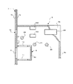
図1乃至図7を参照にして本発明の第1実施例を説明する。まず、環境部材について簡単に説明する。1は寝室、トイレ等の出入口の戸枠、2はストライクを有する受け金具、3は戸枠の縁(直接的にはストライクも含まれる)、4は水平方向に回動して出入口を開閉する扉(例えば室内扉)、5は室内の扉4の戸先に設けられた錠前、本実施例ではプッシュ・プル錠5である。
【0010】
プッシュ・プル錠5の錠箱6には、前板7に対して回動可能に設けられた回動ボタンを回動操作すると、プッシュ・プル錠におけるラッチ施錠片の解除態様が、プッシュ・プル仕様又はプル仕様のいずれかに切り替わるラッチの係止解除機構Xと、開扉の時に不注意によりラッチを施錠した状態で扉を閉めた時にラッチの施錠状態が自動的に解錠状態となるサムターン錠の締め出し防止装置Yとが設けられている。
【0011】
なお、ここで「サムターン錠」を住宅内部におけるハンドル錠の施錠装置の意味合いで用いている。また「回動」の用語は、原則として軸を中心に正逆方向に揺動する円運動の意味合いで用いているが、例外的に回動ボタンは、揺動する場合もあれば、一以上回転する場合もある。
【0012】
次に図2を参照にして錠箱6の構成を説明する。錠箱6は、ケース身6aと、このケース身6aの一側開口を閉鎖する矩形状のケース蓋6bとから成り、前記ケース身6aは前板7を有する。ここで、「前板7」とは、長板状の取付け前板7a又は/及びフロント7bを意味する。取付け前板7aとフロント7bとが別体の場合には、両者は図示しない固着具を介して合体する。
【0013】
8は前板7の中央部に形成した開口窓9を基準としてケース身6aに形成された隔壁状のラッチ枠部で、このラッチ枠部8は、図3で示すように、例えば端面コ字型状に形成されている。ここで図3を参照にしてラッチ枠部8を簡単に説明する。8aは上壁、8bは下壁、8cは上下壁に交差する後壁である。しかして、前記上壁8aにはラッチの係止解除機構Xを構成する第1施錠片用の第1受入れ孔10が形成され、一方、この第1受入れ孔10に対向するように前記下壁8bには、サムターン錠の締め出し防止装置Yを構成する第2施錠片用の第2受入れ孔11が形成されている。
【0014】
第1・第2受入れ孔10,11は、本実施例では開口窓9側から前記後壁8cに向かって形成された水平長孔である。またラッチ枠部8の後壁8cの一側壁(本実施例ではケース身6aの幅広側壁側の側壁)には、上下方向の一部(例えば中央部)に作動杆用の切欠部12が形成されている。
【0015】
14は前板7の上部側に形成された回動ボタン用の支持部の一例としての嵌合孔で、この嵌合孔14の後方には、前板7に所要間隔離間して垂直状態の受け片15が突設されている。
【0016】
ところで、錠箱6には、錠箱内に組み込まれる複数個の摺動部材を水平方向に案内するために、適宜箇所に任意形状の水平案内部(例えば水平長孔、水平溝など)が形成されている。そこで、水平案内部について説明すると、16は前記受け片15を基準にして上下に設けられた第1摺動体用の上方水平案内部、一方、17は錠箱6の下方隅角部に形成されたサムターンダルマ用軸孔18を基準にして上下かつオフセット状態に設けられたリリーススライダー79用の下方水平案内部である。
【0017】
また、本発明の錠前は、プッシュ・プル錠に適用しているので、錠箱6の上部側(例えばサムターンダルマ用軸孔18の真上)には、操作ハンドルに連動する押圧片用の矩形状窓孔20が形成されている。さらに、錠箱6には組み込まれる各部材を揺動させるための固定軸が複数個配設されている。ここで、説明の便宜上、固定軸を上方から順番に説明すると、21はラッチ枠部8の後壁8cの上部付近に設けられた第1固定軸、22はケース身6aの後壁の中央部付近に設けられた第2固定軸、23はラッチ枠部8の後壁8cの下部付近に設けられた第3固定軸、24はラッチ枠部8の下壁の後部側付近に設けられた第4固定軸、そして、25は錠箱の底壁の中央部に設けられた第5固定軸である。
【0018】
錠箱5には、上述したように、回動ボタン用嵌合孔14、該嵌合孔に臨む受け片15、各摺動体を案内する水平案内部16,17、サムターンダルマ用軸孔18、内外の操作ハンドル側の押圧片用窓20,各揺動部材用の複数個の固定軸などが設けられている。なお、本発明の構成に関係のない部分(例えば固着具用螺子部など)は省略してある。
【0019】
次に錠箱に組み込まれる各部材について説明する。30は前板7のフロント板7bを基準に進退動するラッチである。ラッチ30は、公知のように受け金具2のストライクと係合する。ここでのラッチ30は、錠箱6の内部へそのままストレートに後退するもの(普通一般に、「ラッチ」と称されている。)、多少所要角度まで水平回転しながら後退するもの(「反転ラッチ」と称されている。)如何を問わず、戸枠1側に突出して受け金具2に係合するものは、全て含まれる。
ラッチ30の一例は、図3に概略的に示してある。本実施例では反転ラッチが採用されている(反転ラッチに関しては、その一例が特公平2−55591に開示されている)。
【0020】
ここで図1及び図3を参照にしてラッチ30の構成について説明する。30aは戸枠の縁乃至ストライクの開口縁と摺接する垂直状態の衝止面である。30b,30bは、ラッチ30の上下面からそれぞれ凸片状に突出する突起部で、これらの凸片状突起30b,30bはラッチの回転軸としての機能、後述する上下の施錠片とそれぞれ係合する機能を有する。30c,30cはラッチの後端部で、この後端部30c,30cにはラッチバネの一端部を支持するバネ端収納部31が形成されている。
【0021】
32はラッチの作動杆33の端面L型状先端部34に一端部32aが圧接し、一方、その他端部32bがラッチ枠部8の後壁8c内面に圧接するラッチバネである。本実施例では、このラッチバネ32の前記一端部32aが作動杆33の先端部34と共にラッチ30のバネ端収納部31に組み込まれ、ラッチ30を常時突出方向に付勢する。
【0022】
次に図3を参照にして作動杆33について説明する。34は前述したように作動杆32のL型状先端部で、この先端部34は、ラッチ30のバネ端収納部31の内壁面に直接又は間接的に組み込まれ、かつ、ラッチバネ32のバネ力により該内壁面に圧接する。作動杆33の形態に関しては任意に設計変更可能であるが、本実施例では、ラッチバネ32の一端部32aを受けるバネ端支持壁34aを有する先端部34と、前記支持壁34aと交差する先端部一側壁34bに段差状に連設し、かつ、前述したラッチ枠部8の切欠部12に案内される摺動壁35と、この摺動壁35に連設する後端部とから成る。
【0023】
しかして、前記バネ端支持壁34aの内壁面と後端部の前壁面との間には、ラッチ30とラッチ枠部8の位置を考慮してラッチバネ32を組み込むことができるバネ収納空間36が設けられている。また前記後端部には、その後壁面の上端部寄りの部位から底壁面に向かって垂直ないし傾斜状の係合面37aを有する係合切欠部37が形成されている。
【0024】
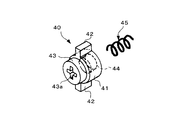
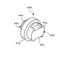
次にラッチの係止解除機構Xを構成する部材について説明する。40は前板7に対して回動可能に設けられた回動ボタンで、この回動ボタン40を略90度回すと、本実施例ではプッシュ・プル錠におけるラッチ施錠片の解除態様が、プッシュ・プル仕様又はプル仕様のいずれかに切り替わる。図1及び図4を参照にして回動ボタン40を説明する。
【0025】
41は周胴部で、この周胴部41は錠箱6の取付け前板7aの内壁面と受け片15の空間部に位置する。42は周胴部41の外周壁面に半径方向に突設された羽状の1又は2以上のストッパー部で、このストッパー部42は、回動ボタン40の回転位置如何によって後述する第2摺動体の前進を規制する機能を果す。43は周胴部41の前面に突設された嵌合突起で、この嵌合突起43は前板7の嵌合孔14に嵌合する。嵌合突起43の前面は、フロント7bの前面と面一であり、図示しない小ドライバー用の溝43aを有する。44は周胴部41の後面に形成されたバネ支持部で、このバネ支持部44は小突起でも良いが、本実施例では凹所状に形成されている。
【0026】
45はバネ支持部44と受け片15との間に設けられた押圧バネで、この押圧バネ45は周胴部41の前面を前板7の内壁面に押し付ける。
【0027】
次に46.47は、錠箱の上方の収納空間に水平状態に配設されたプッシュ・プル用摺動体である。ここでは外枠の摺動体を第1摺動体46、一方、外枠の摺動体内に組み込まれた枠状の摺動体を第2摺動体47とする。また、外側の操作ハンドルに連動する部材を上方の押圧片48とし、一方、内側の操作ハンドルに連動する部材を下方の押圧片49とする。
【0028】
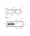
そこで、図5を参照に外枠の第1摺動体46と内側の第2摺動体47とを説明する。まず外枠の第1摺動体46は、図示しない複数個の係合突起を介して錠箱6の上方水平案内部16に水平動自在に設けられている。
【0029】
しかして、46aは上壁部、46bは下壁部、46cは上下壁部と直交する後壁部、46dは後壁部に対して所要の空間を有して対向する前壁部である。前記後壁部46cの内壁面は前述した上下の押圧片48,49を受ける受け板の機能を有する。また前記下壁部46bの一部には揺動レバー用の切欠部51が形成されている。さらに、前記前壁部46dは摺動体用付勢バネ52の一端部を受ける機能や受け片15と当接する機能を有する。しかも、本実施例では、前壁部46dは上下壁部46a,46bの先端部寄りの部位に設けられていると共に、ケース身6aの幅広側壁側には、第2摺動体47の移動を許容する図示しない切欠部を有している。
【0030】
次に、内側の第2摺動体47は、横長のコ型形状に形成され、回動ボタン40及び上下の押圧片48,49にそれぞれ関連付けられて外枠第1摺動体46内に水平動自在に設けられている。
【0031】
しかして、47aは内側の上壁部、47bは内側の下壁部、47cは上下壁部47a,47bと直交する内側の後壁部、47dは後壁部と対抗するバネ受け用隔壁、47eは回動ボタン40のストッパー42と関係する先端部である。
前記内側の上下壁47a,47bの先端部寄りの部位には、前述した前壁部46dに対する逃し用切欠部53が形成され、また前記内側の下壁47bの一部には、揺動レバー用の切欠部51と同様の内側切欠部54が形成されている。さらに、前記バネ受け用隔壁47dは前述した摺動体用付勢バネ52の他端(後端)部を受ける。したがって、摺動体用付勢バネ52は、第1及び第2摺動体46,47内に組み込まれている。
【0032】
次に図1を参照にして揺動レバー55について説明する。アングル状(逆への字状)揺動レバー55は第2固定軸22に軸支されている。本実施例では、第2固定軸22を基準にして第1摺動体46に斜め方向に延びるアーム部56は、第1及び第2摺動体46,47の各切欠部51,54に係合している。一方、第2固定軸22を基準にして下方に延びる連設部分にはバネ受け部57が形成されている。
【0033】
58は第2固定軸22に中央部が巻装された揺動レバー55用バネで、この揺動レバー55用バネ58は揺動レバー55のアーム部56が常時第1及び第2摺動体46,47の各切欠部51,54に係合する方向へと付勢する。ところで、揺動レバー55のアーム部56の先端部には係合突起56aが設けられ、この係合突起56aは、次に説明するラッチ用第1の施錠片60の上辺部分と常に係合している。
【0034】
前記第1の施錠片60は長板状に形成され、第1固定軸21に水平状態に軸支されている。本実施例では、第1固定軸21を基準にして先端部側には、ラッチ枠部8の第1受入れ孔10から入り込んでラッチ30の突起部30bと係脱する幅広の第1係合部61が設けられている。
【0035】
一方、第1固定軸21を基準にして後端部側には、第1摺動体46の後端下部と当接する傾斜状の第2係合部62が設けられている。63は第1固定軸21に中央部が巻装された第1施錠片用バネで、この第1施錠片用バネは、前記第1係合部61がラッチ30の突起部30bに係合する方向へ常時付勢する。
【0036】
そこで、ラッチの係止解除機構Xの作用について説明する。前述したように、本実施例では、前板7の手前から図示しないドライバーの先を溝43aに差し込み、回動ボタン40を回動操作すると、プッシュ・プル錠におけるラッチ施錠片60の解除態様が、プッシュ・プル仕様又はプル仕様(又はプッシュ仕様)のいずれかに切り替わる。
【0037】
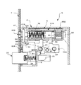
まず、図6は回動ボタン40の羽状ストッパー部42,42が水平状態の場合、当該操作ハンドル(内外の操作ハンドル如何を問わない)を「プル(引く操作)」又は「プッシュ(押す操作)」した場合である。この場合プッシュ・プル錠は、本来的意味でのプッシュ・プル仕様である。
【0038】
すなわち、外側の操作ハンドルであろうと、又は内側の操作ハンドルであろうと、手にした当該操作ハンドルを「プル」又は「プッシュ」すると、第1摺動体46は後退方向へ、又は第2摺動体47は前進方向へそれぞれ移動する。その結果、ラッチ施錠片60はダイレクトに、又は揺動レバー55を介して係合解錠方向へ回動(揺動)する。
【0039】
ここでは前述したように、説明の便宜上、第1摺動体46がプル用として機能した場合(プル用摺動体)、一方、第2摺動体47がプッシュ用として機能した場合(プッシュ用摺動体)を説明する。
【0040】
図1及び図6に於いて、回動ボタン40の羽状ストッパー部42,42が水平状態である。そこで、説明の便宜上、第1摺動体46がプル用として機能した場合(プル用摺動体)、一方、第2摺動体47がプッシュ用として機能した場合(プッシュ用摺動体)をその作用の一例として説明する。
【0041】
すなわち、ここでは外枠の第1摺動体46(一方)を、内外の操作ハンドルを「プル(引く操作)」した時に水平移動するプル用摺動体とし、内側の第2摺動体47(他方)を、内外の操作ハンドルを「プッシュ(押す操作)」した時に水平移動するプッシュ用摺動体とする。
【0042】
また、錠箱6の窓孔20からは、内外の操作ハンドルの作動アームを介して上下の押圧片48,49が水平状態に入り込んでいるが、図1を基準にして上の押圧片48が後退(錠箱の後壁に向かって移動)する場合は「プル時」とし、一方、図1を基準にして下の押圧片49が前進(錠箱の前板に向かって移動)する場合は「プッシュ時」とする。
【0043】
このような前提にて、例えば外側操作ハンドルのプル時(或いは内側操作ハンドルのプル時)には、外枠の第1摺動体46は上方の押圧片48に押されて図6矢印Aの方向に移動する。
【0044】
したがって、ラッチ施錠片60は第1摺動体46の後壁46c下部に押されることになるから、第1固定軸21を支点にバネ63のバネ力に抗して係合解除の方向へダイレクトに回動する。
【0045】
一方、内側操作ハンドルのプシュ時には、今度は内側の第2摺動体47が下方の押圧片49に押されて図6矢印Bの方向に移動する。
【0046】
したがって、ラッチ施錠片60は、揺動レバー55がそのバネ58のバネ力に抗して反時計方向に回動(揺動)することになるから、第1固定軸21を支点に係合解除の方向へ回転する。
【0047】
なお、図6の場合に於いて、例えば内側操作ハンドルのプル時には、外枠の第1摺動体46は下方の押圧片48に押されて図6矢印Aの方向に移動する。また内外操作ハンドルのプシュ時には、内側の第2摺動体47の上下壁47a,47bの先端部は、回動ボタン40の羽状ストッパー部42,42の上下にそれぞれ入り込む。すなわち、内枠の第2摺動体47の先端部47e、47eは、羽状ストッパー部42,42の後端面よりも前板7側へと進入する。
【0048】
これに対して、図7は回動ボタン40の羽状ストッパー部42,42が垂直状態である。この場合には、プッシュ・プル錠におけるラッチ施錠片60の解除態様が、プッシュ・プル仕様から、いずれか一方の仕様(プル仕様、又はプッシュ仕様)に切り替わる。
【0049】
本実施例では、内外の操作ハンドルのプル時に上下の押圧片48,49が図6の矢印A方向へ移動することを前提にしているので、かような前提条件の場合には、プッシュ操作時、内側の第2摺動体47の前進は、可動ポタン40の羽状ストッパー部42,42の後端面に阻まれるので、プッシュ操作でのラッチ施錠片60の係合解除は不可ということになる。
【0050】
一方、プル操作時、外側の第1摺動体46は上下いずれかの押圧片48,49によって矢印A方向へ移動可能なので、ラッチ施錠片60は前述したように係合解除の方向へ回転する。したがって、図7の仕様は、本来的なプッシュ・プル仕様でないから、片面的仕様(プル仕様、又はプッシュ仕様)ということになる。
【0051】
次にサムターン錠の締め出し防止装置Y(以下、「締め出し防止装置」という)について説明する。なお、この締め出し防止装置Yは、ラッチの係止解除機構X(独立項の発明)に対する従属発明なので、ここでは簡単に説明する。この締め出し防止装置Yは、錠箱6のラッチ枠部8を基準として、ラッチの係止解除機構Xを設けた反対側の内部空間、本実施例では下方の収納空間70に組み込まれている。締め出し防止装置Yは、閉戸時に第2のラッチ用施錠片71の係合を解除させるリリース構成部材を有する。
【0052】
図1を参照にして締め出し防止装置Yについて簡単に説明する。71は施錠時に該ラッチ30の移動(回動と後退)を阻止する第2のラッチ用施錠片で、この第2のラッチ用施錠片71は第4固定軸24に軸支され、かつ、施錠片用のバネ72のバネ力により、ラッチの係合方向に常時付勢されている。
【0053】
一方、73は駆動腕74を有するサムターンダルマで、このサムターンダルマ73は軸孔18に回動自在に嵌合している。75は第5固定軸25に巻装されたダルマ用のバネで、このバネ75はサムターンダルマ73の山形状バネ受け部を付勢している。
【0054】
そして、77が前述した作動杆33、第2のラッチ用施錠片71及びサムターンダルマ73にそれぞれ関連付けられたリリース構成部材である。このリリース構成部材77は、作動杆33の係合切欠部37の係合面37aに先端部の係合爪部が係合するように第3固定軸23に軸支されたリリースレバー78と、このリリースレバー78の下端部に先端部側が係合するように設けられ、かつ、水平方向に摺動するスライダー79とから構成され、前記スライダー79の後端部に形成した垂直案内長孔には、サムターンダルマ73の駆動腕74に突設した係合突起が係合している。
【0055】
しかして、扉4の閉戸時、前記ラッチ30が戸枠1の縁3に当って後退すると、リリース構成部材77のリリースレバー78が第3固定軸23を支点に回動することにより、これに連動するスライダー79が前板7方向へ摺動する。
【0056】
そうすると、リリースレバー78の後端部に設けられた不番の係合突起(図1を参照にすると、スライダー79の先端部に形成した垂直案内長孔に位置している円形状の見える部分)の外周面が第2のラッチ用施錠片71の下方の弧状後端部を押し上げるようにスライド係合し、これにより第2のラッチ用施錠片71は、第4固定軸24を支点にバネ72のバネ力に抗して係合解除の方向へと自動的に回転する。
【0057】
したがって、開扉の時に不注意によりラッチを施錠した状態で扉4を閉めた時に、ラッチの施錠状態が常に自動的に解錠状態となるので、いわゆる締め出し防止の効果も得ることができる。
【0058】
【実施例】
本実施例の回動ボタン40は、錠箱6の前板7に形成された嵌合孔14に回動可能に設けられているが、嵌合孔14は回動ボタン用の支持部の一例である。
【0059】
したがって、回動ボタン40の形態を設計変更した場合(例えば嵌合突起43を形成しない場合)には、錠箱6の前板7の内壁面に嵌合孔14を取り囲むように環状(的)突壁を形成し、該環状(的)突壁内に回動ボタン40の周胴部41の先端部側を嵌合しても良い。要は錠箱6に第2摺動体に対する前進を拒むストッパー部を有する部材を回動可能に設ければ良い。
【0060】
次に、この欄では、図8乃至図15に示す第2実施例を説明する。なお、この第2実施例の説明に当たって、前記第1実施例と同一又は同様(機能が同一)の部分には、同一又は同様の符号を付し、重複する説明を省略する。この第2実施例が前記第1実施例と異なる点は、次の通りである。
【0061】
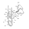
(1)第1実施例の回動ボタン40の形態を一部設計変更したこと。すなわち、図4で示すように、第1実施例の回動ボタン40の周胴部41は円柱状に形成されているのに対し、第2実施例の回動ボタン40Aの周胴部41Aは円板状に形成されている点、回動ボタン40の羽状のストッパー部42は円柱状周胴部41からが上下に突出しているのに対し、回動ボタン40Aのストッパー部42Aは前記周胴部41Aの裏面に突出形成された小判型状の突起部である点、しかも、図10または図11を基準にすると、前記小判型状の突起部の上下の側壁には、図12で示す第2摺動体47Aの上下の先端部47e.47eがスムースに入り込むことができるように一対の逃がし用切欠部42a.42aを形成した点、また、前記周胴部41Aの前面にクリックバネ81の左右の棒状当接部82.82がそれぞれ圧接する角型或いは矩形板状のバネ受け部44Aを突設した点、さらに、この角型バネ受け部44Aの前面に錠箱の前板7の支持部(嵌合孔)14に嵌合し、かつ、マイナス溝43bを有する嵌合突起43Aを設けた点が異なる。
【0062】
(2)第2実施例では、回動ボタン40A用のクリックバネ81を付加したこと。すなわち、第1実施例の回動ボタン40では、回動操作してもクリック感を得ることができない。そこで、第2実施例の回動ボタン40Aでは、図8及び図9で示すように、錠箱6の前板14の内壁面にクリックバネ81を沿うように設け、該クリックバネ81の左右の立ち上がり状当接部82.82を前述した角型バネ受け部44Aの左右側壁に対して複数個のバネ支持手段83.84.84を介し当接状態に配設している。なお、クリックバネ81の中央部は前記前板14に固定したバネ支持手段83に支持され、また、クリックバネ81の左右の立ち上がり状当接部82.82は、前板14に固定した左右一対の突起状バネ支持手段84.84に支持されている。
【0063】
(3)第1摺動体46A及び第2摺動体47Aの形態を一部変更している。すなわち、第1実施例では逃し用切欠部53を第2摺動体47に形成しているが、第2実施例では第1摺動体46Aの前壁部46dに第2摺動体47Aの先端部47e。47e用の逃し用切欠部53A.53Aを形成している点、第2実施例の第2摺動体47Aのバネ受け用の隔壁47dは、上下壁部47a.47bの一部を内側に折り曲げて形成されている点である。
【0064】
(4)第1実施例では押圧バネ45、受け片15などを有しているが、第2実施例ではこれらの部材が存在しないこと。すなわち、第2実施例では回動ボタン40Aの後方のストッパー部42Aが第1摺動体46Aの前壁部46dの前面に当接可能であることから、押圧バネ45や受け片15を設けていない。なお、細部的事項ではあるが、図9で示すように、第2実施例の錠箱6では、突起状バネ支持手段84付近に施錠片用のバネの一端部を受けるバネ受け85を設けている。また、上下の水平案内部16A.16Aの大きさなども異なる。
【0065】
(5)ラッチ用の施錠片60Aと作動レバー55Aの組み合わせが異なる。施錠片60A及び作動レバー55Aの具体的な構成態様の説明に関しては割愛するが、第2実施例では作動レバー55A用の付勢バネを減らすために、ラッチ用の施錠片60Aの後端部に可動突起軸86を設け、一方、作動レバー55Aの先端部に前記可動突起軸86と係合する係合長孔87を形成した点が主に異なる。換言すれば、ラッチ用の施錠片60Aは作動レバー55Aに連動するように可動突起軸86及び係合長孔87を介して連結されている。
【0066】
(6)図8及び図13で示すように、ラッチ用の施錠片60Aの垂直状第2係合部62は第1摺動体46Aの後壁ではなく、矢印で示すように下壁部46bの切欠部51の切欠端面に係合する。
【0067】
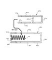
(7)回動ボタン40Aのストッパー部42Aは、プッシュ・プル仕様時の時は、図14で示すように水平状態となり、一方、片面的仕様(例えばプル仕様)時は、図15で示すように垂直状態となる。回動ボタン40Aを回動操作した場合に於いて、ラッチ施錠片60Aの解除態様が、プッシュ・プル仕様から、いずれか一方の仕様(プル仕様、又はプッシュ仕様)に切り替わる作用については、第1実施例と同様なので説明を割愛する。
【0068】
上記のように構成を設計変更しても、第1実施例と同一の目的・作用を得ることができる。発明の効果に関しては、上下の押圧片48.49により摺動体46A.47Aが水平動した時にラッチ用の施錠片60Aや作動レバー55Aがスムースに作動する、部品点数(例えばバネ、受け片など)が少なく成る、回動ボタン40Aを操作した時にクリック感が得られるなど付加的効果を得ることができる。
【0069】
【発明の効果】
以上の説明から明らかなように、本発明にあっては、次に列挙するような効果がある。
(1)ユーザーが建物の扉の取付け場所を考慮し、プッシュ・プル仕様と、片面的仕様(プル仕様、又はプッシュ仕様)とを、自由に選択することができる。
(2)上記(1)に於いて、錠箱の前板から見える回動ボタン40を所定量回動するだけの操作で、例えばプッシュ・プル仕様から片面的仕様に、又は片面的仕様から本来的なプッシュ・プル仕様に切替えることができることができる。
(3)錠箱内に第1摺動体と第2摺動体を合理的に組み込むことができる。
)請求項に記載の発明は、さらに、回動ボタン40Aを操作した時にクリック感を得ることができる。
)その他、錠箱内にサムターン錠の締め出し防止装置Yを組み込むことができる。
【図面の簡単な説明】
図1乃至図7は、本発明の第1実施例を示す各説明図。図8乃至図15は、本発明の第2実施例を示す各説明図。
【図1】扉の閉戸時における本来的なプッシュ・プル仕様態様を示す説明図。
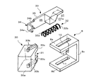
【図2】ケース身を主とした錠箱の説明図。
【図3】ラッチ、ラッチ枠部、作動杆等の説明図。
【図4】回動ボタン等の説明図。
【図5】第1・第2摺動体等の説明図。
【図6】プッシュ・プル仕様時の作動状態の説明図。
【図7】片面的仕様(例えばプル仕様)時の作動状態の説明図。
【図8】第2実施例の概略説明図。
【図9】錠箱の主要部を示す説明図。
【図10】回動ボタンの斜視図。
【図11】回動ボタンと関係する部材の説明図。
【図12】第2実施例の各摺動体の説明図(なお、第2摺動体は中央部を縦断面で示している)。
【図13】回動ボタン以外の主な構成部材の斜視図。
【図14】プッシュ・プル仕様時の回動ボタンの位置を示す説明図。
【図15】片面的仕様(例えばプル仕様)時の回動ボタンの位置を示す説明図。
【符号の説明】
X…ラッチの係止解除機構、Y…サムターン錠の締め出し防止機構、
1…戸枠、2…受け金具、3…縁、4…扉、5…錠前、6…錠箱、7…前板、8…ラッチ枠部、9…開口窓、14…嵌合孔、15…受け片、20…窓孔、21〜25…固定軸、30…ラッチ、32…ラッチバネ、33…作動杆、37…係合切欠部、37a…係合面、40.40A…回動ボタン、41.41A…周胴部、42.42A…ストッパー部、43.43A…嵌合突起、44…バネ支持部、44A…バネ受け部、45…押圧バネ、46.46A…第1摺動体、47.47A…第2摺動体、51,54…揺動レバー用の切欠部、55.55A…揺動レバー、56…アーム部、58…揺動レバー用バネ、60.60A…ラッチ用施錠片、61…第1係合部、62…第2係合部、63…施錠片用バネ、70…下方の収納空間、71…第2のラッチ用施錠片、73…サムターンダルマ、77…リリース構成部材、78…リリースレバー、79…スライダー、81…クリックバネ82…当接部、83.84…バネ支持部、85…可動突起軸、87…係合長孔。
[0001]
BACKGROUND OF THE INVENTION
The present invention relates to a push-pull lock, and in particular, when a door is closed, when an internal or external operation handle is pulled or pushed, the latch-locking release mechanism causes the latching locking piece to rotate in the unlocking direction. Regarding locks.
[0002]
[Prior art]
  Conventionally, a number of push-pull locks having a latch, a locking piece for latching when the door is closed, and an unlocking mechanism for the locking piece have been proposed by the Japan Patent Office (for example, JP-A-11-50707). Publication).
[0003]
  By the way, it is now possible for the user (customer) to freely select either push-pull specifications or single-sided specifications (pull specifications or push specifications) in consideration of the installation location of the building door. Although the appearance of a lock is desired, a push-pull lock that satisfies this demand has not yet been proposed.
[0004]
[Problems to be solved by the invention]
  Accordingly, a first object of the present invention is to provide a push / pull specification in which the user can freely select a push / pull specification and a one-sided specification (pull specification or push specification) in consideration of the installation location of the door. To provide a pull tablet. The second purpose is to simply rotate the rotation button (40.40A) visible from the front plate of the lock box by a predetermined amount, for example, from the push-pull specification to the one-sided specification or from the one-sided specification. It is possible to switch to a simple push-pull specification. The third purpose is to rationally incorporate the first sliding body and the second sliding body in the lock box. The fourth object is that the latching locking piece and the operating lever operate smoothly when the sliding body moves horizontally by the pressing piece. The fifth purpose is to reduce the number of parts (for example, springs, receiving pieces, etc.). The sixth purpose is to obtain a click feeling when the rotation button 40 is operated. Another object is that the thumb-turn lockout prevention device Y can be incorporated in the lock box.
[0005]
[Means for Solving the Problems]
  In the push-pull lock of the present invention, when the operation handle is pulled or pushed, the latch locking piece pivotally supported in the lock box and locking the latch rotates in the direction of disengagement of the latch. In the push-pull lock provided with the mechanism, the pressing pieces 48 and 49 that are moved by the operation of the operation handle are connected to the lock box 6.ofArranged in the internal space of the lock box through the window hole 20,A first sliding body 46 of the outer frame that is movable in the horizontal direction by the pressing force of the pressing pieces 48 and 49 and a second sliding body 47 of the inner frame incorporated in the first sliding body of the outer frame are placed in the lock box. Provided inAnd furtherSaid to face the tip of the second sliding body of the inner frameLockboxOf front plate 7A rotation button (40, 40A) having a stopper portion (42, 42A) is provided on the support portion 14, and the rotation button is rotated by a predetermined amount.When the stopper part is displacedThe aboveInner frameOf the second sliding bodyToward the front plate 7When the advancement is blocked by the stopper portion, the original push / pull specification is switched to a one-sided specification mode such as a pull specification or a push specification.
[0006]
  In the above-described configuration, the stopper portion 42 of the rotation button 40 is a protruding portion formed in a wing shape on the peripheral wall of the peripheral body portion 41. Further, the stopper portion 42A of the rotation button 40A is a protruding portion formed to protrude from the back surface of the peripheral body portion 41A.
[0007]
  In the above configuration,Outer frameWhen the first sliding body 46 moves toward the rear wall of the lock box, the latch locking piece 60 isOuter frameIt is pushed by the first sliding body 46 and rotates directly in the direction of disengagement against the spring force of the locking piece spring 63. Also,Inner frameWhen the second sliding body 47 moves in the direction of the front plate of the lock box, the latch locking piece 60 is pivotally supported in the lock box and the swing lever 55 that rotates against the spring force of the spring 58 is provided. It is characterized by rotating in the direction of disengagement.
[0008]
  Further, in the above configuration, the second sliding body 47 of the inner frame is incorporated in the first sliding body 46 of the frame so as to be relatively movable, and the horizontal wall portions of the first and second sliding bodies 46 and 47 are arranged. Is formed with notches 51 and 54 with which the arm portion 56 of the swing lever 55 is engaged. In addition, the lock boxFront plateThe click spring 81 that contacts the rotation button 40A isMultipleIt is provided through a spring support means 84.
[0009]
DETAILED DESCRIPTION OF THE INVENTION
  A first embodiment of the present invention will be described with reference to FIGS. First, the environmental member will be briefly described. 1 is a door frame of an entrance / exit of a bedroom, toilet, etc., 2 is a bracket having a strike, 3 is an edge of the door frame (directly includes a strike), 4 is horizontally rotated to open and close the entrance / exit A door (for example, an indoor door) 5 is a lock provided at the door end of the indoor door 4, which is a push-pull lock 5 in this embodiment.
[0010]
  In the lock box 6 of the push-pull lock 5, when the rotation button provided so as to be rotatable with respect to the front plate 7 is rotated, the release state of the latch locking piece in the push-pull lock is changed to the push-pull. Latch release mechanism X that switches to either specification or pull specification, and thumb turn that automatically unlocks when the door is closed with the latch locked inadvertently when the door is opened A lockout prevention device Y is provided.
[0011]
  Here, “thumbturn lock” is used to mean a locking device for a handle lock inside a house. The term “rotation” is used in the meaning of a circular motion that swings in the forward and reverse directions around the axis as a rule. Sometimes it rotates.
[0012]
  Next, the configuration of the lock box 6 will be described with reference to FIG. The lock box 6 includes a case body 6 a and a rectangular case lid 6 b that closes one side opening of the case body 6 a, and the case body 6 a has a front plate 7. Here, the “front plate 7” means the long plate-shaped front plate 7a and / or the front 7b. In the case where the pre-mounting plate 7a and the front 7b are separate bodies, they are combined via a fixing tool (not shown).
[0013]
  Reference numeral 8 denotes a partition-like latch frame formed on the case body 6a with reference to an opening window 9 formed at the center of the front plate 7. The latch frame 8 is formed, for example, as a U-shaped end face as shown in FIG. It is formed in a mold shape. Here, the latch frame portion 8 will be briefly described with reference to FIG. 8a is an upper wall, 8b is a lower wall, and 8c is a rear wall that intersects the upper and lower walls. Thus, the upper wall 8a is formed with a first receiving hole 10 for the first locking piece constituting the latch release mechanism X, while the lower wall is opposed to the first receiving hole 10. A second receiving hole 11 for a second locking piece constituting the thumb turn lockout prevention device Y is formed in 8b.
[0014]
  In the present embodiment, the first and second receiving holes 10 and 11 are horizontal long holes formed from the opening window 9 side toward the rear wall 8c. Further, on one side wall of the rear wall 8c of the latch frame portion 8 (in this embodiment, the side wall on the wide side wall side of the case body 6a), a cutout portion 12 for the operating rod is formed in a part in the vertical direction (for example, the central portion). Has been.
[0015]
  Reference numeral 14 denotes a fitting hole as an example of a support portion for a rotation button formed on the upper side of the front plate 7. The fitting hole 14 has a vertical space apart from the front plate 7 at a predetermined interval behind the fitting hole 14. A receiving piece 15 is projected.
[0016]
  By the way, in the lock box 6, in order to guide the plurality of sliding members incorporated in the lock box in the horizontal direction, a horizontal guide portion having an arbitrary shape (for example, a horizontal long hole, a horizontal groove, etc.) is formed at an appropriate position. Has been. Accordingly, the horizontal guide portion will be described. 16 is formed at the upper horizontal guide portion for the first sliding body provided above and below the receiving piece 15, and 17 is formed at the lower corner portion of the lock box 6. This is a lower horizontal guide portion for the release slider 79 which is provided vertically and offset with respect to the thumb turn dharma shaft hole 18.
[0017]
  In addition, since the lock of the present invention is applied to a push-pull lock, the upper side of the lock box 6 (for example, directly above the shaft hole 18 for thumb turn dharma) is a rectangular for a pressing piece interlocking with an operation handle. A shaped window hole 20 is formed. Further, the lock box 6 is provided with a plurality of fixed shafts for swinging each member to be incorporated. Here, for convenience of explanation, the fixed shaft will be described in order from the top. 21 is a first fixed shaft provided near the upper portion of the rear wall 8c of the latch frame portion 8, and 22 is a central portion of the rear wall of the case body 6a. A second fixed shaft provided in the vicinity, 23 a third fixed shaft provided near the lower portion of the rear wall 8c of the latch frame portion 8, and 24 a second fixed shaft provided near the rear side of the lower wall of the latch frame portion 8. Reference numeral 4 denotes a fixed shaft, and reference numeral 25 denotes a fifth fixed shaft provided at the center of the bottom wall of the lock box.
[0018]
  As described above, the lock box 5 has a rotation button fitting hole 14, a receiving piece 15 facing the fitting hole, horizontal guide portions 16 and 17 for guiding each sliding body, a thumb turn dharma shaft hole 18, Window for pressing pieces on the inner and outer operating handlesHole20. A plurality of fixed shafts for each swing member are provided. Note that portions not related to the configuration of the present invention (for example, a screw portion for fixing tool) are omitted.
[0019]
  Next, each member incorporated in the lock box will be described. Reference numeral 30 denotes a latch that moves forward and backward with reference to the front plate 7b of the front plate 7. The latch 30 engages with the strike of the catch 2 as is well known. Here, the latch 30 is retracted straight into the lock box 6 as it is (usually generally referred to as “latch”), and is retracted while horizontally rotating to a required angle (“inverted latch”). Regardless of the case, all of them that protrude toward the door frame 1 and engage with the metal fitting 2 are included.
An example of the latch 30 is shown schematically in FIG. In this embodiment, an inverting latch is adopted (an example of the inverting latch is disclosed in Japanese Patent Publication No. 2-55591).
[0020]
  Here, the configuration of the latch 30 will be described with reference to FIGS. Reference numeral 30a denotes a vertical stop surface in sliding contact with the edge of the door frame or the opening edge of the strike. 30b and 30b are latches30The protrusions 30b and 30b are protrusions protruding from the upper and lower surfaces of the upper and lower surfaces, respectively, and the protrusions 30b and 30b have a function as a rotation shaft of the latch and a function of engaging with upper and lower locking pieces described later. Reference numerals 30c and 30c denote rear end portions of the latch, and the rear end portions 30c and 30c are formed with spring end accommodating portions 31 for supporting one end portion of the latch spring.
[0021]
  Reference numeral 32 denotes a latch spring in which one end 32 a is pressed against the end face L-shaped tip 34 of the latch operating rod 33 and the other end 32 b is pressed against the inner surface of the rear wall 8 c of the latch frame 8. In this embodiment, the one end portion 32a of the latch spring 32 is incorporated into the spring end accommodating portion 31 of the latch 30 together with the tip end portion 34 of the operating rod 33, and the latch 30 is always urged in the protruding direction.
[0022]
  Next, the operating rod 33 will be described with reference to FIG. 34 is the L-shaped tip of the operating rod 32 as described above, and this tip 34 is directly or indirectly incorporated into the inner wall surface of the spring end housing 31 of the latch 30 and the spring force of the latch spring 32. To press against the inner wall surface. Although the design of the operating rod 33 can be arbitrarily changed, in this embodiment, the tip 34 having a spring end support wall 34a for receiving one end 32a of the latch spring 32, and the tip that intersects the support wall 34a. The sliding wall 35 is provided in a stepped manner on the one side wall 34 b and guided by the notch 12 of the latch frame portion 8 described above, and a rear end portion connected to the sliding wall 35.
[0023]
  Thus, between the inner wall surface of the spring end support wall 34a and the front wall surface of the rear end portion, the latch 30 andLatch frameA spring accommodating space 36 in which the latch spring 32 can be incorporated in consideration of the position of 8 is provided. Also saidRear edgeThen, an engagement notch 37 having a vertical or inclined engagement surface 37a from the portion near the upper end of the wall surface toward the bottom wall surface is formed.
[0024]
  Next, members constituting the latch release mechanism X will be described. Reference numeral 40 denotes a rotation button provided so as to be rotatable with respect to the front plate 7. When this rotation button 40 is rotated by approximately 90 degrees, the release mode of the latch locking piece in the push-pull lock is pushed in this embodiment.・ Switch to either pull specification or pull specification. The rotation button 40 will be described with reference to FIGS. 1 and 4.
[0025]
  Reference numeral 41 denotes a peripheral drum portion, and the peripheral drum portion 41 is located on the inner wall surface of the mounting front plate 7 a of the lock box 6 and the space portion of the receiving piece 15. Reference numeral 42 denotes one or more wing-like stoppers protruding in the radial direction on the outer peripheral wall surface of the peripheral body part 41. The stopper part 42 advances the second sliding body, which will be described later, depending on the rotational position of the rotary button 40. Acts to regulate 43 is a fitting projection provided on the front surface of the peripheral body 41, and this fitting projection 43 is fitted in the fitting hole 14 of the front plate 7. The front surface of the fitting protrusion 43 is flush with the front surface of the front 7b, and has a groove 43a for a small driver (not shown). Reference numeral 44 denotes a spring support portion formed on the rear surface of the peripheral body portion 41. The spring support portion 44 may be a small protrusion, but is formed in a recess shape in this embodiment.
[0026]
  Reference numeral 45 denotes a pressing spring provided between the spring support portion 44 and the receiving piece 15, and the pressing spring 45 presses the front surface of the peripheral body portion 41 against the inner wall surface of the front plate 7.
[0027]
  Next, 46.47 is a lock box6Is a push-pull sliding body disposed in a horizontal state in the storage space above. Here, the sliding body of the outer frame is referred to as the first sliding body 46, while the frame-shaped sliding body incorporated in the sliding body of the outer frame is referred to as the second sliding body 47. Further, a member interlocking with the outer operation handle is referred to as an upper pressing piece 48, while a member interlocking with the inner operation handle is referred to as a lower pressing piece 49.
[0028]
  Therefore, the first sliding body 46 of the outer frame and the second sliding body 47 on the inner side will be described with reference to FIG. First, the first sliding body 46 of the outer frame is provided on the upper horizontal guide portion 16 of the lock box 6 so as to be horizontally movable via a plurality of engaging projections (not shown).
[0029]
  46a is an upper wall portion, 46b is a lower wall portion, 46c is a rear wall portion orthogonal to the upper and lower wall portions, and 46d is a front wall portion facing the rear wall portion with a predetermined space. The inner wall surface of the rear wall portion 46c functions as a receiving plate that receives the upper and lower pressing pieces 48 and 49 described above. Further, a notch 51 for a swing lever is formed in a part of the lower wall portion 46b. Further, the front wall portion 46 d has a function of receiving one end portion of the sliding body biasing spring 52 and a function of contacting the receiving piece 15. In addition, in this embodiment, the front wall portion 46d is provided near the tip of the upper and lower wall portions 46a and 46b, and the second sliding body 47 is allowed to move on the wide side wall side of the case body 6a. It has a notch (not shown).
[0030]
  Next, the second sliding body 47 on the inner sideCharacterIt is formed in a mold shape and is provided in the outer frame first sliding body 46 so as to be horizontally movable in association with the rotation button 40 and the upper and lower pressing pieces 48 and 49, respectively.
[0031]
  47a is an inner upper wall portion, 47b is an inner lower wall portion, 47c is an inner rear wall portion orthogonal to the upper and lower wall portions 47a and 47b, 47d is a spring receiving partition wall facing the rear wall portion, 47e. Is the stopper of the rotation button 40Part42 is a tip portion related to 42.
The above-described relief cutout 53 for the front wall 46d is formed in a portion of the inner upper and lower walls 47a and 47b near the tip, and a part of the inner lower wall 47b is provided for the swing lever. An inner notch 54 similar to the notch 51 is formed. Further, the spring receiving partition wall 47d receives the other end (rear end) portion of the sliding body biasing spring 52 described above. Therefore, the urging spring 52 for the sliding body is incorporated in the first and second sliding bodies 46 and 47.
[0032]
  Next, the swing lever 55 will be described with reference to FIG. The angle-shaped (inverted character shape) swing lever 55 is pivotally supported by the second fixed shaft 22. In the present embodiment, the arm portion 56 extending obliquely to the first sliding body 46 with respect to the second fixed shaft 22 is engaged with the notches 51 and 54 of the first and second sliding bodies 46 and 47. ing. On the other hand, a spring receiving portion 57 is formed in a continuous portion extending downward with respect to the second fixed shaft 22.
[0033]
  Reference numeral 58 denotes a spring for the swing lever 55 having a central portion wound around the second fixed shaft 22. The spring 58 for the swing lever 55 is such that the arm portion 56 of the swing lever 55 always has the first and second sliding bodies 46. , 47 is urged in a direction to engage with the notches 51, 54. Incidentally, an engaging projection 56a is provided at the tip of the arm portion 56 of the swing lever 55, and this engaging projection 56a is always engaged with the upper side portion of the first locking piece 60 for latch described below. ing.
[0034]
  The first locking piece 60 is formed in a long plate shape and is pivotally supported by the first fixed shaft 21 in a horizontal state. In the present embodiment, a wide first engaging portion that enters from the first receiving hole 10 of the latch frame portion 8 and engages and disengages with the protruding portion 30 b of the latch 30 on the tip end side with respect to the first fixed shaft 21. 61 is provided.
[0035]
  On the other hand, on the rear end side with respect to the first fixed shaft 21, an inclined second engaging portion 62 that comes into contact with the lower end of the rear end of the first sliding body 46 is provided. Reference numeral 63 denotes a first locking piece spring having a central portion wound around the first fixed shaft 21. The first locking piece spring has the first engaging portion 61 engaged with the protrusion 30 b of the latch 30. Always energize in the direction.
[0036]
  Therefore, the operation of the latch release mechanism X will be described. As described above, in this embodiment, when the tip of a driver (not shown) is inserted into the groove 43a from the front of the front plate 7 and the rotation button 40 is rotated, the release mode of the latch locking piece 60 in the push-pull lock is as follows. , Switch to either push-pull specification or pull specification (or push specification).
[0037]
  First, in FIG. 6, when the wing-like stopper portions 42, 42 of the rotation button 40 are in a horizontal state, the operation handle (regardless of whether the operation handle is inside or outside) is “pull (pulling operation)” or “push (pushing operation). ) ”. In this case, the push-pull lock is a push-pull specification in the original sense.
[0038]
  That is, whether the operation handle is an outer operation handle or an inner operation handle, when the operation handle held in hand is “pulled” or “pushed”, the first sliding body 46 moves backward or the second sliding body. 47 respectively move in the forward direction. As a result, the latch locking piece 60 rotates (swings) directly or via the swing lever 55 in the engaging / unlocking direction.
[0039]
  Here, as described above, for convenience of explanation, when the first sliding body 46 functions for pulling (pull sliding body), on the other hand, when the second sliding body 47 functions for pushing (pushing sliding body). Will be explained.
[0040]
  In FIG.1 and FIG.6, the wing-like stopper parts 42 and 42 of the rotation button 40 are a horizontal state. Therefore, for convenience of explanation, an example of the action is when the first sliding body 46 functions for pulling (pull sliding body), while the second sliding body 47 functions for pushing (pushing sliding body). Will be described.
[0041]
  That is, here, the first sliding body 46 (one side) of the outer frame is a pulling sliding body that moves horizontally when the inner and outer operation handles are “pulled (pulled)”, and the inner second sliding body 47 (the other). Is a sliding body for push that moves horizontally when the inner and outer operation handles are “pushed (pressed)”.
[0042]
  In addition, the upper and lower pressing pieces 48 and 49 enter the horizontal state from the window hole 20 of the lock box 6 through the operation arms of the inner and outer operation handles. When retreating (moving toward the rear wall of the lock box), “when pulling”, while when the lower pressing piece 49 moves forward (moves toward the front plate of the lock box) with reference to FIG. “When pushing”.
[0043]
  Under such a premise, for example, when the outer operation handle is pulled (or when the inner operation handle is pulled), the first sliding body 46 of the outer frame is pushed by the upper pressing piece 48 and the direction of arrow A in FIG. Move to.
[0044]
  Therefore, since the latch locking piece 60 is pushed by the lower part of the rear wall 46c of the first sliding body 46, the first locking shaft 21 is used as a fulcrum to resist the spring force of the spring 63 and directly in the direction of disengagement. Rotate.
[0045]
  On the other hand, at the time of pushing the inner operation handle, the inner second sliding body 47 is pushed by the lower pressing piece 49 and moves in the direction of arrow B in FIG.
[0046]
  Therefore, the latch locking piece 60 is disengaged with the first fixed shaft 21 as a fulcrum because the swing lever 55 rotates (swings) counterclockwise against the spring force of the spring 58. Rotate in the direction of.
[0047]
  In the case of FIG. 6, for example, when the inner operation handle is pulled, the first sliding body 46 of the outer frame is pushed by the lower pressing piece 48 and moves in the direction of arrow A in FIG. When the inner / outer operation handle is pushed, the tip portions of the upper and lower walls 47a, 47b of the inner second sliding body 47 enter above and below the wing-like stopper portions 42, 42 of the rotation button 40, respectively.That is, the front end portions 47e and 47e of the second sliding body 47 of the inner frame enter the front plate 7 side from the rear end surfaces of the wing-like stopper portions 42 and 42.
[0048]
  On the other hand, in FIG. 7, the wing-like stopper portions 42, 42 of the rotation button 40 are in a vertical state. In this case, the release mode of the latch locking piece 60 in the push / pull lock is switched from the push / pull specification to one of the specifications (pull specification or push specification).
[0049]
  In the present embodiment, it is assumed that the upper and lower pressing pieces 48 and 49 move in the direction of arrow A in FIG. 6 when the inner and outer operation handles are pulled. The forward movement of the inner second sliding body 47 is performed by the wing-like stopper portions 42, 42 of the movable button 40.Rear end faceTherefore, it is impossible to disengage the latch locking piece 60 by a push operation.
[0050]
  On the other hand, during the pulling operation, the outer first sliding body 46 can be moved in the direction of arrow A by any one of the upper and lower pressing pieces 48, 49, so that the latch locking piece 60 rotates in the direction of disengagement as described above. Therefore, since the specification of FIG. 7 is not an original push-pull specification, it is a one-sided specification (pull specification or push specification).
[0051]
Next, the thumb-turn lockout prevention device Y (hereinafter referred to as “lockout prevention device”) will be described. The anti-lock-out device Y is a dependent invention with respect to the latch release mechanism X (independent invention), and will be briefly described here.thisThe lockout prevention device Y is incorporated in the internal space on the opposite side where the latch release mechanism X is provided, in the present embodiment, the lower storage space 70 with reference to the latch frame portion 8 of the lock box 6. The lockout prevention device Y has a release component that releases the engagement of the second latching locking piece 71 when the door is closed.
[0052]
  With reference to FIG. 1, the lockout prevention device Y will be briefly described. Reference numeral 71 denotes a second latching locking piece for preventing the movement (turning and retreating) of the latch 30 during locking. The second latching locking piece 71 is pivotally supported by the fourth fixed shaft 24 and is locked. The spring force of the single spring 72 is always urged in the latch engagement direction.
[0053]
  On the other hand, reference numeral 73 denotes a thumb turn dharma having a drive arm 74, and the thumb turn dharma 73 is rotatably fitted in the shaft hole 18. Reference numeral 75 denotes a dharma spring wound around the fifth fixed shaft 25, and this spring 75 biases the mountain-shaped spring receiving portion of the thumb turn dharma 73.
[0054]
  Reference numeral 77 denotes release components associated with the operating rod 33, the second latch locking piece 71 and the thumb turn dharma 73, respectively. The release component 77 includes a release lever 78 that is pivotally supported by the third fixed shaft 23 so that the engagement claw portion at the distal end engages with the engagement surface 37a of the engagement notch 37 of the operating rod 33; A vertical guide slot formed in the rear end portion of the slider 79 includes a slider 79 that is provided so that the tip end side engages with the lower end portion of the release lever 78 and slides in the horizontal direction. The engaging protrusions protruding from the drive arm 74 of the thumb turn dharma 73 are engaged.
[0055]
  When the door 4 is closed, when the latch 30 comes into contact with the edge 3 of the door frame 1 and retreats, the release lever 78 of the release component 77 rotates about the third fixed shaft 23, thereby The slider 79 interlocking with the slider slides in the direction of the front plate 7.
[0056]
  Then, it was provided at the rear end of the release lever 78.Unnumbered engagement protrusionAs shown in FIG. 1, the outer peripheral surface of the circular visible portion located in the vertical guide slot formed at the tip of the slider 79 is an arcuate rear end below the second latch locking piece 71. The second latch locking piece 71 is automatically rotated in the direction of disengagement against the spring force of the spring 72 with the fourth fixed shaft 24 as a fulcrum. .
[0057]
  Therefore, when the door 4 is closed in a state where the latch is inadvertently locked when the door is opened, the latched state is always automatically unlocked, so that a so-called lock-out preventing effect can be obtained.
[0058]
【Example】
  Although the rotation button 40 of the present embodiment is rotatably provided in the fitting hole 14 formed in the front plate 7 of the lock box 6, the fitting hole 14 is an example of a support portion for the rotation button. It is.
[0059]
  Therefore, when the design of the rotation button 40 is changed (for example, when the fitting protrusion 43 is not formed), the annular hole is formed so as to surround the fitting hole 14 on the inner wall surface of the front plate 7 of the lock box 6. A protruding wall may be formed, and the distal end side of the peripheral body 41 of the rotation button 40 may be fitted into the annular (target) protruding wall. In short, a member having a stopper portion that refuses to advance relative to the second sliding body may be provided in the lock box 6 so as to be rotatable.
[0060]
  Next, in this section, a second embodiment shown in FIGS. 8 to 15 will be described. In the description of the second embodiment, the same or similar parts (functions are the same) as those in the first embodiment are denoted by the same or similar reference numerals, and redundant description is omitted. The second embodiment is different from the first embodiment as follows.
[0061]
  (1) The design of the form of the rotation button 40 of the first embodiment is partially changed. That is, as shown in FIG. 4, the circumferential body 41 of the rotation button 40 of the first embodiment is formed in a columnar shape, whereas the circumferential body 41A of the rotation button 40A of the second embodiment is formed in a disk shape. On the other hand, the wing-like stopper portion 42 of the rotation button 40 protrudes vertically from the cylindrical peripheral body portion 41, whereas the stopper portion 42A of the rotation button 40A protrudes from the back surface of the peripheral body portion 41A. 10 and FIG. 11, the upper and lower side walls of the oval-shaped protrusions are provided on the upper and lower sides of the second sliding body 47A shown in FIG. Tip portion 47e. A pair of relief cutouts 42a. 47e so that 47e can enter smoothly. 42a is formed, and a square or rectangular plate-shaped spring receiving portion 44A is provided on the front surface of the peripheral body portion 41A so that the left and right rod-like contact portions 82.82 of the click spring 81 are in pressure contact with each other. The difference is that a fitting protrusion 43A having a minus groove 43b is provided on the front surface of the square spring receiving portion 44A to be fitted into the support portion (fitting hole) 14 of the front plate 7 of the lock box.
[0062]
  (2) In the second embodiment, a click spring 81 for the rotation button 40A is added. That is, with the rotation button 40 of the first embodiment, a click feeling cannot be obtained even if the rotation operation is performed. Therefore, in the rotation button 40A of the second embodiment, as shown in FIGS. 8 and 9, the click spring 81 is provided along the inner wall surface of the front plate 14 of the lock box 6, and the left and right sides of the click spring 81 are The rising contact portion 82.82 is disposed in contact with the left and right side walls of the square spring receiving portion 44A described above via a plurality of spring support means 83.84.84. The central portion of the click spring 81 is supported by a spring support means 83 fixed to the front plate 14, and the left and right rising contact portions 82.82 of the click spring 81 are a pair of left and right fixed to the front plate 14. Is supported by the protruding spring support means 84.84.
[0063]
  (3) The form of the first sliding body 46A and the second sliding body 47A is partially changed. That is, in the first embodiment, the relief notch 53 is formed in the second sliding body 47, but in the second embodiment, the front end portion 47e of the second sliding body 47A is formed on the front wall portion 46d of the first sliding body 46A. . 47e relief notch 53A. 53A, the partition wall 47d for receiving the spring of the second sliding body 47A of the second embodiment is provided with upper and lower wall portions 47a. It is a point formed by bending a part of 47b inward.
[0064]
  (4) The first embodiment has the pressing spring 45, the receiving piece 15 and the like, but these members are not present in the second embodiment. That is, in the second embodiment, since the stopper portion 42A behind the rotation button 40A can contact the front surface of the front wall portion 46d of the first sliding body 46A, the pressing spring 45 and the receiving piece 15 are not provided. . Although it is a detailed matter, as shown in FIG. 9, in the lock box 6 of the second embodiment, a spring receiver 85 for receiving one end of the spring for the locking piece is provided in the vicinity of the protruding spring support means 84. Yes. The upper and lower horizontal guide portions 16A. The size of 16A is also different.
[0065]
  (5) The combination of the locking piece 60A for latch and the operating lever 55A is different. The description of the specific configuration of the locking piece 60A and the operating lever 55A is omitted, but in the second embodiment, in order to reduce the biasing spring for the operating lever 55A, the latching locking piece 60A has a rear end portion. The main difference is that a movable protrusion shaft 86 is provided, while an engagement elongated hole 87 that engages with the movable protrusion shaft 86 is formed at the tip of the operating lever 55A. In other words, the latching locking piece 60A is connected via the movable protrusion shaft 86 and the engagement elongated hole 87 so as to be interlocked with the operation lever 55A.
[0066]
  (6) As shown in FIGS. 8 and 13, the vertical second engaging portion 62 of the locking piece 60A for latch is not the rear wall of the first sliding body 46A, but the lower wall portion 46b as shown by an arrow. Engage with the notch end face of the notch 51.
[0067]
  (7) The stopper portion 42A of the rotation button 40A is in a horizontal state as shown in FIG. 14 when in the push-pull specification, while as shown in FIG. 15 in the one-sided specification (for example, the pull specification). It becomes a vertical state. When the rotation button 40A is rotated, the release mode of the latch locking piece 60A is switched from the push / pull specification to one of the specifications (pull specification or push specification). Since it is the same as that of an Example, description is omitted.
[0068]
  Even if the configuration is changed as described above, the same objects and effects as in the first embodiment can be obtained. Regarding the effect of the invention, the upper and lower pressing pieces 48.49 cause the sliding body 46A. The locking piece 60A for latching and the operating lever 55A operate smoothly when the 47A moves horizontally, the number of parts (for example, springs, receiving pieces, etc.) decreases, and a click feeling is obtained when the rotary button 40A is operated. Additional effects can be obtained.
[0069]
【The invention's effect】
  As is clear from the above description, the present invention has the following effects.
(1) The user can freely select the push-pull specification and the one-sided specification (pull specification or push specification) in consideration of the installation location of the building door.
(2) In the above (1), the rotation button 40 visible from the front plate of the lock box is simply rotated by a predetermined amount, for example, from the push / pull specification to the one-sided specification or from the one-sided specification. Can be switched to a typical push-pull specification.
(3) The first sliding body and the second sliding body can be rationally incorporated in the lock box.
(4Claim6Furthermore, the invention described in (1) can provide a click feeling when the rotation button 40A is operated.
(5In addition, the thumb-turn lockout prevention device Y can be incorporated in the lock box.
[Brief description of the drawings]
1 to 7 are explanatory views showing a first embodiment of the present invention. 8 to 15 are explanatory views showing a second embodiment of the present invention.
FIG. 1 is an explanatory diagram showing an original push / pull specification mode when a door is closed.
FIG. 2 is an explanatory diagram of a lock box mainly made of a case.
FIG. 3 is an explanatory diagram of a latch, a latch frame, an operating rod, and the like.
FIG. 4 is an explanatory diagram of a rotation button and the like.
FIG. 5 is an explanatory diagram of first and second sliding bodies and the like.
FIG. 6 is an explanatory diagram of an operating state at the time of push-pull specification.
FIG. 7 is an explanatory diagram of an operating state in one-sided specification (for example, pull specification).
FIG. 8 is a schematic explanatory diagram of a second embodiment.
FIG. 9 is an explanatory view showing the main part of the lock box.
FIG. 10 is a perspective view of a rotation button.
FIG. 11 is an explanatory diagram of members related to a rotation button.
FIG. 12 is an explanatory diagram of each sliding body of the second embodiment (note that the second sliding body shows a central portion in a longitudinal section).
FIG. 13 is a perspective view of main constituent members other than a rotation button.
FIG. 14 is an explanatory diagram showing the position of a rotation button in push / pull specification.
FIG. 15 is an explanatory view showing the position of a rotation button in one-sided specification (for example, pull specification).
[Explanation of symbols]
X ... Latch release mechanism, Y ... Thumb turn lockout prevention mechanism,
DESCRIPTION OF SYMBOLS 1 ... Door frame, 2 ... Receiving metal fitting, 3 ... Edge, 4 ... Door, 5 ... Lock, 6 ... Lock box, 7 ... Front plate, 8 ... Latch frame part, 9 ... Opening window, 14 ... Fitting hole, 15 ... receiving piece, 20 ... window hole, 21-25 ... fixed shaft, 30 ... latch, 32 ... latch spring, 33 ... operating rod, 37 ... engagement notch, 37a ... engagement surface, 40.40A ... rotation button, 41.41A ... Circumferential body part, 42.42A ... Stopper part, 43.43A ... Fitting protrusion, 44 ... Spring support part, 44A ... Spring receiving part, 45 ... Pressing spring, 46.46A ... First sliding body, 47.47A ... second sliding body, 51, 54 ... notch portion for swing lever, 55.55A ... swing lever, 56 ... arm portion, 58 ... spring for swing lever, 60.60A ... locking piece for latch, 61 ... 1st engaging part, 62 ... 2nd engaging part, 63 ... Spring for locking piece, 70 ... Lower storage space, 71 ... 2nd roller Locking piece for h, 73 ... Thumb turn dharma, 77 ... Release component, 78 ... Release lever, 79 ... Slider, 81 ... Click spring 82 ... Abutment, 83.84 ... Spring support, 85 ... Movable protrusion shaft, 87 ... engagement long hole.

Claims (8)

操作ハンドルをプル又はプッシュすると、錠箱内に軸支されかつラッチを係止しているラッチ施錠片が係合解除の方向へ回動するラッチの係止解除機構を備えたプッシュ・プル錠に於いて、前記操作ハンドルの操作によって移動する押圧片48、49を錠箱6の窓孔20を介して錠箱の内部空間に配設し、また、前記押圧片48、49の押圧力によって水平方向へ移動可能な外枠の第1摺動体46と該外枠の第1摺動体内に組み込まれた内枠の第2摺動体47を錠箱内に設け、さらに、前記内枠の第2摺動体の先端部と対向するように前記錠箱の前板7の支持部14にストッパー部(42、42A)を有する回動ボタン(40、40A)を設け、前記回動ボタンを所定量回動して前記ストッパー部を位置変位させると、前記内枠の第2摺動体の前記前板7方向への前進が前記ストッパー部に阻止されることによって、本来的なプッシュ・プル仕様からプル仕様、又はプッシュ仕様というような片面的仕様態様に切り替わることを特徴とするプッシュ・プル錠。  When the operation handle is pulled or pushed, the push / pull lock is equipped with a latch release mechanism that is pivotally supported in the lock box and the latch locking piece that locks the latch rotates in the direction of disengagement. In this case, the pressing pieces 48 and 49 that are moved by the operation of the operation handle are disposed in the internal space of the lock box through the window hole 20 of the lock box 6, and the pressing pieces 48 and 49 are horizontally moved by the pressing force of the pressing pieces 48 and 49. A first sliding body 46 of the outer frame movable in the direction and a second sliding body 47 of the inner frame incorporated in the first sliding body of the outer frame are provided in the lock box, and the second sliding body of the inner frame is further provided. A rotation button (40, 40A) having a stopper portion (42, 42A) is provided on the support portion 14 of the front plate 7 of the lock box so as to face the front end portion of the sliding body, and the rotation button is rotated a predetermined amount. When the stopper is moved and displaced, the second sliding body of the inner frame The push-pull is switched from the original push-pull specification to the one-sided specification mode such as the pull specification or the push specification by preventing the forward movement in the direction of the front plate 7 by the stopper portion. Tablets. 請求項1に於いて、回動ボタン40のストッパー部42は、周胴部41の周壁に羽状に突出形成された突起部であることを特徴とするプッシュ・プル錠。  2. The push-pull lock according to claim 1, wherein the stopper portion of the rotary button is a protrusion formed in a wing shape on the peripheral wall of the peripheral body portion. 請求項1に於いて、外枠の第1摺動体46が錠箱の後壁方向へ移動した時、ラッチ施錠片60は、外枠の第1摺動体46に押され、かつ施錠片用バネ63のバネ力に抗してダイレクトに係合解除の方向へ回転することを特徴とするプッシュ・プル錠。  The latch locking piece 60 is pushed by the first sliding body 46 of the outer frame and the spring for the locking piece when the first sliding body 46 of the outer frame moves toward the rear wall of the lock box. A push-pull lock that rotates directly in the direction of disengagement against the spring force of 63. 請求項1に於いて、内枠の第2摺動体47が錠箱の前板方向へ移動した時、ラッチ施錠片60は、錠箱内に軸支され、かつ、バネ58のバネ力に抗して回動する揺動レバー55を介して係合解除の方向へ回転することを特徴とするプッシュ・プル錠。  In claim 1, when the second sliding body 47 of the inner frame moves toward the front plate of the lock box, the latch locking piece 60 is pivotally supported in the lock box and resists the spring force of the spring 58. A push-pull lock that rotates in the direction of disengagement through a pivoting lever 55 that rotates. 請求項4に於いて、外枠の第1摺動体46に内枠の第2摺動体47が相対的に移動可能に組み込まれ、該第1及び第2摺動体46,47の水平壁部には、揺動レバー55のアーム部56が係合する切欠部51,54がそれぞれ形成されていることを特徴とするプッシュ・プル錠。 In Claim 4 , the 2nd sliding body 47 of an inner frame is integrated in the 1st sliding body 46 of an outer frame so that a relative movement is possible, and it attaches to the horizontal wall part of these 1st and 2nd sliding bodies 46 and 47 The push-pull lock is characterized in that notches 51 and 54 with which the arm portion 56 of the swing lever 55 is engaged are respectively formed. 請求項1に於いて、錠箱の前板には、回動ボタン40Aに当接するクリックバネ81を、複数個のバネ支持手段84を介して設けたことを特徴とするプッシュ・プル錠。  2. The push-pull lock according to claim 1, wherein the front plate of the lock box is provided with a click spring 81 abutting against the rotation button 40A via a plurality of spring support means 84. 請求項1に於いて、回動ボタン40Aのストッパー部42Aは、その周胴部41Aの裏面に突出形成された突起部であることを特徴とするプッシュ・プル錠。    4. The push-pull lock according to claim 1, wherein the stopper part 42A of the rotation button 40A is a protrusion formed on the back surface of the peripheral body part 41A. 請求項7に於いて、突起部の側壁に、内枠の第2摺動体47Aの先端部47eが入り込むことができるように逃がし用切欠部42aを形成したことを特徴とするプッシュ・プル錠。  8. The push-pull lock according to claim 7, wherein a relief cutout 42a is formed in the side wall of the protrusion so that the tip 47e of the second sliding body 47A of the inner frame can enter.
JP2003155013A 2002-11-12 2003-05-30 Push-Pull Tablet Expired - Fee Related JP4424924B2 (en)

Priority Applications (2)

Application Number Priority Date Filing Date Title
JP2003155013A JP4424924B2 (en) 2002-11-12 2003-05-30 Push-Pull Tablet
TW93115496A TWI343961B (en) 2003-05-30 2004-05-31 Push-pull lock

Applications Claiming Priority (2)

Application Number Priority Date Filing Date Title
JP2002327646 2002-11-12
JP2003155013A JP4424924B2 (en) 2002-11-12 2003-05-30 Push-Pull Tablet

Publications (2)

Publication Number Publication Date
JP2004211529A JP2004211529A (en) 2004-07-29
JP4424924B2 true JP4424924B2 (en) 2010-03-03

Family

ID=32828404

Family Applications (1)

Application Number Title Priority Date Filing Date
JP2003155013A Expired - Fee Related JP4424924B2 (en) 2002-11-12 2003-05-30 Push-Pull Tablet

Country Status (1)

Country Link
JP (1) JP4424924B2 (en)

Families Citing this family (4)

* Cited by examiner, † Cited by third party
Publication number Priority date Publication date Assignee Title
JP2007046330A (en) * 2005-08-10 2007-02-22 Miwa Lock Co Ltd Push/pull lock
JP4741927B2 (en) * 2005-10-13 2011-08-10 美和ロック株式会社 Door lock
JP2007120057A (en) * 2005-10-26 2007-05-17 Miwa Lock Co Ltd Push-pull lock
JP2007186919A (en) * 2006-01-13 2007-07-26 Miwa Lock Co Ltd Lock switching mechanism

Also Published As

Publication number Publication date
JP2004211529A (en) 2004-07-29

Similar Documents

Publication Publication Date Title
JP4741927B2 (en) Door lock
JP4424924B2 (en) Push-Pull Tablet
KR101663162B1 (en) Door Lock having Rotatable Latch Bolt
JP4823874B2 (en) Electric lock
JP2003160288A5 (en)
JP4368565B2 (en) Stopper mechanism for reverse latch of lock
JP4546034B2 (en) Latch pullback device for door lock
JP5070521B2 (en) Reverse latch lock
JP2007169880A (en) Push-pull lock
JP2007046330A (en) Push/pull lock
JP4206255B2 (en) Door lock
JP2007032188A (en) Push-pull lock
JP2006328882A (en) Lock for door
JP5130256B2 (en) Lock-out prevention device for thumb turn lock on indoor door
JP2007162297A (en) Bush-pull lock
AU2009101386A4 (en) A Sliding Door Lock
JP6216132B2 (en) Push-pull tablet
KR20050115458A (en) Push-pull lock
JP2007032049A (en) Push-pull lock
JP2877394B2 (en) Tablets
JP3428293B2 (en) Locking device for door or drawer in cabinet
JP2000054703A (en) Door lock
JP2004225384A (en) Push/pull lock
JP2023147414A (en) Home delivery box
JPH0241255Y2 (en)

Legal Events

Date Code Title Description
A621 Written request for application examination

Free format text: JAPANESE INTERMEDIATE CODE: A621

Effective date: 20060508

A977 Report on retrieval

Free format text: JAPANESE INTERMEDIATE CODE: A971007

Effective date: 20090120

A131 Notification of reasons for refusal

Free format text: JAPANESE INTERMEDIATE CODE: A131

Effective date: 20090203

A521 Written amendment

Free format text: JAPANESE INTERMEDIATE CODE: A523

Effective date: 20090309

A131 Notification of reasons for refusal

Free format text: JAPANESE INTERMEDIATE CODE: A131

Effective date: 20090623

A521 Written amendment

Free format text: JAPANESE INTERMEDIATE CODE: A523

Effective date: 20090727

TRDD Decision of grant or rejection written
A01 Written decision to grant a patent or to grant a registration (utility model)

Free format text: JAPANESE INTERMEDIATE CODE: A01

Effective date: 20091201

A01 Written decision to grant a patent or to grant a registration (utility model)

Free format text: JAPANESE INTERMEDIATE CODE: A01

A61 First payment of annual fees (during grant procedure)

Free format text: JAPANESE INTERMEDIATE CODE: A61

Effective date: 20091208

R150 Certificate of patent or registration of utility model

Free format text: JAPANESE INTERMEDIATE CODE: R150

FPAY Renewal fee payment (event date is renewal date of database)

Free format text: PAYMENT UNTIL: 20121218

Year of fee payment: 3

FPAY Renewal fee payment (event date is renewal date of database)

Free format text: PAYMENT UNTIL: 20121218

Year of fee payment: 3

FPAY Renewal fee payment (event date is renewal date of database)

Free format text: PAYMENT UNTIL: 20131218

Year of fee payment: 4

R250 Receipt of annual fees

Free format text: JAPANESE INTERMEDIATE CODE: R250

R250 Receipt of annual fees

Free format text: JAPANESE INTERMEDIATE CODE: R250

LAPS Cancellation because of no payment of annual fees