JP4801581B2 - Containers equipped in the vehicle - Google Patents
Containers equipped in the vehicle Download PDFInfo
- Publication number
- JP4801581B2 JP4801581B2 JP2006351738A JP2006351738A JP4801581B2 JP 4801581 B2 JP4801581 B2 JP 4801581B2 JP 2006351738 A JP2006351738 A JP 2006351738A JP 2006351738 A JP2006351738 A JP 2006351738A JP 4801581 B2 JP4801581 B2 JP 4801581B2
- Authority
- JP
- Japan
- Prior art keywords
- drawer
- pin
- guide groove
- open position
- fully
- Prior art date
- Legal status (The legal status is an assumption and is not a legal conclusion. Google has not performed a legal analysis and makes no representation as to the accuracy of the status listed.)
- Expired - Fee Related
Links
Images


Classifications
-
- B—PERFORMING OPERATIONS; TRANSPORTING
- B62—LAND VEHICLES FOR TRAVELLING OTHERWISE THAN ON RAILS
- B62K—CYCLES; CYCLE FRAMES; CYCLE STEERING DEVICES; RIDER-OPERATED TERMINAL CONTROLS SPECIALLY ADAPTED FOR CYCLES; CYCLE AXLE SUSPENSIONS; CYCLE SIDE-CARS, FORECARS, OR THE LIKE
- B62K19/00—Cycle frames
- B62K19/46—Luggage carriers forming part of frame
Landscapes
- Engineering & Computer Science (AREA)
- Mechanical Engineering (AREA)
- Passenger Equipment (AREA)
- Closures For Containers (AREA)
Description
本発明は、車両に装備される物入れの改良に関する。 The present invention relates to an improvement of a storage case installed in a vehicle.
小物を収納する引き出しとこの引き出しを水平スライド可能に収納する収納ケースと、引き出しが乗員側へ引き出される際に、中間位置で引き出しを一旦停止させる中開停止機構とを備え車両に装備される物入れが知られている(例えば、特許文献1参照。)。
特許文献1の図11において、車両の前部には、ヘッドパイプを後方から覆うとともに車体カバー34(符号は同公報のものを流用する。以下同じ。)の一部を構成するインナカバー157と、このインナカバー157の開口部に設けた格納壁197と、この格納壁197の内側に水平スライド可能に設けた引き出しとが備えられている。 In FIG. 11 of Patent Document 1, an inner cover 157 that covers a head pipe from the rear and forms a part of a vehicle body cover 34 (reference numerals are those of the same publication; the same applies hereinafter) is provided at the front of the vehicle. A storage wall 197 provided in the opening of the inner cover 157 and a drawer provided in the storage wall 197 so as to be horizontally slidable are provided.
特許文献1の図18において、インナカバーと引き出しの間には、引き出しを中間位置(中開位置)保持させる保持機構230(以下、「中開停止機構230」と云う。)が備えられている。
中開位置における保持状態を解除するには、運転者が揺動係合部材235を図の矢印に示す方向に回動操作して、係合凹部238の係止軸232への係合を解除する。係合が解除されると、引き出しは開放側に付勢されているので、開放側に開放される。
In FIG. 18 of Patent Document 1, between the inner cover and the drawer, a holding mechanism 230 that holds the drawer in an intermediate position (medium open position) (hereinafter referred to as “medium open stop mechanism 230”) is provided. .
In order to release the holding state in the middle open position, the driver rotates the swing engagement member 235 in the direction indicated by the arrow in the figure to release the engagement of the engagement recess 238 from the locking shaft 232. To do. When the engagement is released, the drawer is biased to the open side, so that it is released to the open side.
ところで、揺動係合部材235は、引き出しの下方に設けられている。運転者が引き出しを全開位置にする際には、運転者が引き出しの下方に手を入れて揺動係合部材235を操作する必要があり、操作は煩雑なものとなる。また、揺動係合部材235を操作するとき、運転者の体格によっては、かがむ動作が必要となり、操作は一層煩雑なものとなる。
全閉位置と全開位置の間の中開位置で保持する機構を有する引き出しにおいて、引き出しを中開位置から全開位置にする操作を、容易に行うことができる技術があれば好ましい。
By the way, the swing engaging member 235 is provided below the drawer. When the driver sets the drawer to the fully open position, the driver needs to put his hand under the drawer to operate the swing engagement member 235, and the operation becomes complicated. Further, when operating the swing engaging member 235, a crouching operation is required depending on the physique of the driver, and the operation becomes more complicated.
In a drawer having a mechanism for holding it in the middle open position between the fully closed position and the fully open position, it is preferable to have a technique that can easily perform the operation of changing the drawer from the middle open position to the fully open position.
本発明は、中開位置で保持する機構を有する引き出しにおいて、引き出しを中開位置から全開位置する操作を容易に行うことができる物入れを提供することを課題とする。 An object of the present invention is to provide a container in which a drawer having a mechanism for holding in a middle open position can be easily operated to fully open the drawer from the middle open position.
請求項1に係る発明は、小物を収納する引き出しと、この引き出しを水平スライド可能に収納する収納ケースと、引き出しが乗員側へ引き出される際に中間位置で引き出しを一旦停止させる中開停止機構からなる、車両に装備される物入れにおいて、収納ケースに、全閉位置にある引き出しを開放側に、全開位置に至るまで弾発付勢する弾発機構と、中開停止機構により、中開位置で停止した引き出しを、閉じる方向に操作せしめることで、中開停止機構を解除させる停止解除機構を備え、引き出しは、閉じる方向に操作され、中開停止機構を解除された後に全開位置で停止することを特徴とする。 The invention according to claim 1 includes a drawer for storing small articles, a storage case for storing the drawer in a horizontally slidable manner, and an intermediate opening stop mechanism for temporarily stopping the drawer at an intermediate position when the drawer is pulled out to the occupant side. In the case where the vehicle is equipped with a storage case, the storage case has a drawer mechanism in which the drawer in the fully-closed position is opened to the open side, and a bullet-opening mechanism and a middle-open stop mechanism in the middle-open position. It has a stop release mechanism that releases the middle-open stop mechanism by operating the stopped drawer in the closing direction, and the drawer is operated in the closing direction and stops at the fully-open position after the middle-open stop mechanism is released. It is characterized by.
請求項2に係る発明は、中開停止機構は、引き出し若しくは収納ケースに水平旋回可能に設けられ先端にピン状突起を備えているアーム部材と、ピン状突起を案内するために収納ケース若しくは引き出しに、引き出しのスライド方向に延設された溝群とからなり、この溝群は、引き出しの全開位置から全閉位置までピン状突起を案内する第1ガイド溝と、全閉位置を起点として第1ガイド溝とは別個にほぼ直線的に延ばされ、引き出しの全閉位置から中開位置までピン状突起を案内する第2ガイド溝と、この第2ガイド溝の端部に設けられピン状突起を中開位置で一旦停める袋小路部と、この袋小路部から全閉位置側へ傾斜して延ばされ第1ガイド溝の途中に交叉する連絡溝と、からなり、引き出しを開けると、ピン状突起が直線状の第2ガイド溝を進むため袋小路部で一旦停められ、次に引き出しを少し戻すことでピン状突起が連絡溝を進んで第1ガイド溝に移り、次に引き出しが引き出されることでピン状突起は第1ガイド溝を進み全開に到り、引き出しを閉じるときにはピン状突起が第1ガイド溝を進むことで全開位置から全閉位置に到るように構成したことを特徴とする。 According to a second aspect of the present invention, the intermediate opening stop mechanism includes an arm member provided on the drawer or storage case so as to be horizontally pivotable and provided with a pin-like protrusion at the tip, and a storage case or drawer for guiding the pin-like protrusion. And a groove group extending in the sliding direction of the drawer. The groove group includes a first guide groove for guiding the pin-shaped protrusion from the fully open position of the drawer to the fully closed position, and a first position starting from the fully closed position. A second guide groove that extends substantially linearly separately from the one guide groove and guides the pin-shaped protrusion from the fully closed position to the middle open position of the drawer, and a pin-like shape provided at the end of the second guide groove It consists of a bag path that temporarily stops the protrusion in the middle open position, and a communication groove that extends from the bag path toward the fully closed position and crosses in the middle of the first guide groove. Projection is a straight second In order to proceed through the groove, it is temporarily stopped at the bag path, and then the drawer is slightly returned to move the pin-like protrusion through the connecting groove to the first guide groove, and then the drawer is pulled out so that the pin-like protrusion is the first. When the guide groove is advanced to reach the full open position and the drawer is closed, the pin-shaped protrusion advances through the first guide groove to reach the fully closed position.
請求項3に係る発明は、第2ガイド溝を全閉位置から中開位置へ向かって進むピン状突起の通過は許容するが、ピン状突起が全閉位置へ戻ることは妨げる逆止機構を、前記袋小路部の入口に付設したことを特徴とする The invention according to claim 3 is provided with a check mechanism that allows the pin-like protrusion to pass through the second guide groove from the fully closed position toward the middle open position but prevents the pin-like protrusion from returning to the fully closed position. , Characterized by being attached to the entrance of the bag path
請求項4に係る発明は、袋小路部を平面視でV字状にするとともに第1ガイド溝と第2ガイド溝と連絡溝とで囲われる部分を三角形部にし、この三角形部の袋小路に面する頂点よりも、袋小路部のV字底が第1ガイド溝寄りに位置するように袋小路部を定めたことを特徴とする。 In the invention according to claim 4, the bag path portion is formed in a V shape in a plan view, and a portion surrounded by the first guide groove, the second guide groove, and the communication groove is formed in a triangular portion, and faces the bag path of the triangular portion. The bag path portion is defined such that the V-shaped bottom of the bag path portion is located closer to the first guide groove than the apex.
請求項5に係る発明では、溝群は、収納ケースに設け、アーム部材は、引き出しに設けることを特徴とする。 The invention according to claim 5 is characterized in that the groove group is provided in the storage case and the arm member is provided in the drawer.
請求項6に係る発明では、第2ガイド溝の端部又は第1ガイド溝の端部は、収納ケースの端部まで延出して開放される開放端を有し、この開放端を末広がりに形成することを特徴とする。
請求項7に係る発明では、収納ケースに弾発機構が設けられ、この弾発機構により引き出しが全閉状態から全開状態になるように力が加わるように構成され、ピン状突起が一旦袋小路部にて止められた後に、引き出しを少し戻すと、ピン突起は連絡溝を通って第1ガイド溝に進入して引き出しが全開となることを特徴とする。
In the invention which concerns on Claim 6, the edge part of a 2nd guide groove or the edge part of a 1st guide groove has an open end extended to the edge part of a storage case, and this open end is formed in a divergent form It is characterized by doing.
In the invention according to claim 7, a resilient mechanism is provided in the storage case, and by this resilient mechanism, a force is applied so that the drawer is changed from the fully closed state to the fully opened state, and the pin-shaped protrusion is once the bag path portion. When the drawer is slightly returned after being stopped by the pin, the pin protrusion passes through the communication groove and enters the first guide groove, so that the drawer is fully opened.
請求項1に係る発明では、収納ケースには、全閉位置にある引き出しを開放側に、全開位置に至るまで弾発付勢する弾発機構と、中開停止機構により、中開位置で停止した引き出しを、閉じる方向に操作せしめることで、中開停止機構を解除させる停止解除機構とが備えられている。 In the invention according to claim 1, the storage case is stopped at the middle open position by the bullet opening mechanism that urges the drawer in the fully closed position to the open side until it reaches the full open position, and the middle opening stop mechanism. The drawer is operated in the closing direction, and a stop release mechanism for releasing the intermediate opening stop mechanism is provided.
引き出しは、弾発機構と中開停止機構により、中開位置まで開放され、次に、中開位置で停止した引き出しを、閉じる方向に操作せしめることで、停止解除機構により解除され、全開位置に開放させることができる。つまり、運転者は引き出しを押す操作をするだけで、中開位置から全開位置にすることができる。
従って、運転者は、中開位置にある引き出しを全開位置まで開く操作を極めて容易に行うことができる。
The drawer is released to the middle open position by the elastic mechanism and the middle opening stop mechanism, and then the drawer stopped at the middle opening position is operated in the closing direction to be released by the stop release mechanism and to the fully opened position. It can be opened. That is, the driver can move from the middle open position to the fully open position only by pressing the drawer.
Therefore, the driver can perform the operation of opening the drawer in the middle open position to the fully open position very easily.
請求項2に係る発明では、中開停止機構には、引き出し又は収納ケースの一方に、ピン状突起を有するアーム部材が配置され、引き出し又は収納ケースの他方に、ピン状突起を案内する溝群とが各々配置されている。また、溝群は、第1ガイド溝と、第2ガイド溝と、この第2ガイド溝の端部に設けられる袋小路部と、この袋小路部から全閉位置側へ傾斜して延ばされ第1ガイド溝に交叉する連絡溝と、からなる。 In the invention according to claim 2, in the middle opening stop mechanism, an arm member having a pin-shaped protrusion is disposed on one of the drawer or the storage case, and a groove group for guiding the pin-shaped protrusion on the other of the drawer or the storage case And are arranged respectively. The groove group includes a first guide groove, a second guide groove, a bag path portion provided at an end of the second guide groove, and a first inclined path extending from the bag path portion toward the fully closed position. And a communication groove intersecting with the guide groove.
引き出しを開けると、ピン状突起が袋小路部で一旦停められることで、引き出しを中開位置まで引き出すことができる。次に引き出しを少し戻すことで、ピン状突起は袋小路部から連絡溝を通り第1ガイド溝に移り、次に引き出しを引くことでピン状突起は第1ガイド溝を進み、引き出しを全開位置まで引き出ことができる。つまり、運転者は押し引きするだけで、引き出しを中開位置から全開位置にすることができる。
従って、運転者は、中開位置にある引き出しを全開位置まで開く操作を極めて容易に行える。運転者の体格によって引き出しの開き操作が煩雑となることもない。
When the drawer is opened, the pin-shaped protrusion is temporarily stopped at the bag path, so that the drawer can be pulled out to the middle open position. Next, by slightly returning the drawer, the pin-shaped protrusion moves from the bag path through the connecting groove to the first guide groove, and then by pulling the drawer, the pin-shaped protrusion advances through the first guide groove to bring the drawer to the fully open position. Can be withdrawn. That is, the driver can move the drawer from the middle open position to the fully open position only by pushing and pulling.
Therefore, the driver can very easily perform the operation of opening the drawer in the middle open position to the fully open position. Depending on the physique of the driver, the drawer opening operation is not complicated.
また、そのような引き出しの操作のための構造をピン状突起とガイド溝によりシンプルに構成したので、部品点数を極力少なくすることができる上に、コストも低く抑えることができる。 In addition, since the structure for such a drawer operation is simply configured by the pin-like protrusion and the guide groove, the number of parts can be reduced as much as possible, and the cost can be reduced.
請求項3に係る発明は、第2ガイド溝を全閉位置から中開位置へ向かって進むピン状突起の通過は許容するが、ピン状突起が全閉位置へ戻ることは妨げる逆止機構を、袋小路部の入口に付設したので、ピン状突起が袋小路部に到達すると、ピン状突起は袋小路部から第2ガイド溝に戻ることはない。
ピン状突起が第2ガイド溝に戻ることはないので、引き出しを中開位置から全開位置に確実に開放させることができる。
The invention according to claim 3 is provided with a check mechanism that allows the pin-like protrusion to pass through the second guide groove from the fully closed position toward the middle open position but prevents the pin-like protrusion from returning to the fully closed position. Since it is attached to the entrance of the bag alley portion, when the pin-like projection reaches the bag alley portion, the pin-like projection does not return from the bag alley portion to the second guide groove.
Since the pin-shaped protrusion does not return to the second guide groove, the drawer can be reliably opened from the middle open position to the fully open position.
請求項4に係る発明では、引き出しには、開放側に弾発付勢する弾発機構を設けたので、中開位置で、ピン状突起は袋小路部に当たり付勢されている。
袋小路部を平面視でV字状にするとともに第1ガイド溝と第2ガイド溝と連絡溝とで囲われる部分を三角形部にし、この三角形部の袋小路に面する頂点よりも、袋小路部のV字底が第1ガイド溝寄りに位置するように袋小路部を定めたので、袋小路部に入ったピン状突起は、引き出しを少し戻したときに、連絡溝に移行する。
In the invention according to claim 4, since the drawer is provided with a resilient mechanism for resiliently urging toward the open side, the pin-like protrusion is urged against the bag path portion at the middle open position.
The bag path portion is formed into a V shape in plan view, and the portion surrounded by the first guide groove, the second guide groove, and the communication groove is formed into a triangular portion. Since the bag path portion is determined so that the bottom of the letter is located closer to the first guide groove, the pin-like protrusions that have entered the bag path portion shift to the communication groove when the drawer is slightly returned.
また、引き出しには、開放側に弾発付勢する弾発機構を設けるとともに、袋小路部のV字底が第1ガイド溝寄りに位置するように袋小路部を定めた。このように、弾発機構を付設し袋小路部の配置を工夫することによって、引き出しを中開位置から全開位置にするときには、ピン状突起を連絡溝に移行させ、第1ガイド溝に移行させることができるので、引き出しを全開位置に開放させることができる。 In addition, the drawer is provided with a bullet mechanism that urges and urges the opening toward the open side, and the bag path portion is determined so that the V-shaped bottom of the bag path portion is located closer to the first guide groove. As described above, when the drawer is moved from the middle open position to the fully open position by attaching the elastic mechanism and devising the arrangement of the bag path portion, the pin-shaped protrusion is moved to the communication groove and is moved to the first guide groove. Therefore, the drawer can be opened to the fully open position.
袋小路部のV字底が第1ガイド溝寄りに位置するように袋小路部を定めたので、袋小路部の入口に逆止機構を付設することなく、ピン状突起を連絡溝に移行させ、第1ガイド溝に移行させることができるので、引き出しを全開位置に開放させることができる。
逆止機構が不要となるので、中開停止機構の構造を簡便にすることができる。
Since the bag path portion is determined so that the V-shaped bottom of the bag path portion is located closer to the first guide groove, the pin-shaped protrusion is moved to the communication groove without providing a check mechanism at the inlet of the bag path portion, and the first Since it can be shifted to the guide groove, the drawer can be opened to the fully open position.
Since the check mechanism is not required, the structure of the intermediate opening stop mechanism can be simplified.
請求項5に係る発明では、溝群は、収納ケースに設けられている。すなわち、溝群は引き出し側に設けていないため、溝群によって引き出しの収納容量が減ることはなく、十分な量の収納容量を確保することができる。
引き出しを外したときには、引き出し側に設けられているアーム部材のメンテナンスを容易に行うことができる。
In the invention according to claim 5, the groove group is provided in the storage case. That is, since the groove group is not provided on the drawer side, the storage capacity of the drawer is not reduced by the groove group, and a sufficient amount of storage capacity can be secured.
When the drawer is removed, maintenance of the arm member provided on the drawer side can be easily performed.
請求項6に係る発明では、第2ガイド溝の端部又は第1ガイド溝の端部は、収納ケースの端部まで延出して開放される開放端を有するので、ピン状突起を有するアーム部材を溝群に容易に嵌合させることができる。従って、引き出しを収納ケースに容易に組み付けることができる。
請求項7に係る発明では、引き出しを中間位置から全開位置に開けるときは、引き出しを少し戻すと、ピン状突起は連絡溝を通って第1ガイド溝に進入して引き出しが全開となるように構成したので、運転者は、中開位置にある引き出しを全開位置まで開く操作を極めて容易に行うことができる。押し引きする操作のみで引き出しを中開位置から全開位置に開くことができるので、運転者の体格によって引き出しの開く操作が煩雑となることもない。
In the invention according to claim 6, since the end portion of the second guide groove or the end portion of the first guide groove has an open end that extends to the end portion of the storage case and is opened, an arm member having a pin-like protrusion Can be easily fitted in the groove group. Therefore, the drawer can be easily assembled to the storage case.
In the invention according to claim 7, when the drawer is opened from the intermediate position to the fully open position, when the drawer is slightly returned, the pin-like protrusion enters the first guide groove through the communication groove so that the drawer is fully opened. Since it comprised, the driver | operator can perform the operation which opens the drawer | drawer in a middle open position to a full open position very easily. Since the drawer can be opened from the middle open position to the fully open position only by pushing and pulling, the operation of opening the drawer is not complicated depending on the physique of the driver.
本発明を実施するための最良の形態を添付図に基づいて以下に説明する。なお、図面は符号の向きに見るものとする。
図1は本発明に係る自動二輪車の左側面図であり、自動二輪車10は、ヘッドパイプ11の上部から斜め後下に延びているメインフレーム12L、12R(手前側の符号12Lのみ示す。)と、前記ヘッドパイプ11の下部から斜め後下に延び、次いで略下に延び、最後に後方に延びて前記メインフレーム12L、12Rに連結されているダウンフレーム13L、13R(手前側の符号13Lのみ示す。)と、前記メインフレーム12L、12Rの後部から斜め後上に延びているシートレール14L、14R(手前側の符号14Lのみ示す。)と、このシートレール14L、14Rの中間点16L、16R(手前側の符号16Lのみ示す。)と前記メインフレーム12L、12Rの後端部との間を連結しているミドルフレーム17L、17R(手前側の符号17Lのみ示す。)と、これらのミドルフレーム17L、17Rの上部と前記シートレール14L、14Rの後部との間を連結しているレールステー18L、18R(手前側の符号18Lのみ示す。)と、前記シートレール14L、14Rとミドルフレーム17L、17Rとの間に掛け渡してピボット軸19を支持しているピボットプレート21L、21R(手前側の符号21Lのみ示す。)と、これらのピボットプレート21L、21Rにピボット軸19を介して下方に延びているリンク部材22と、このリンク部材22及び支持軸23を介して後方に延びており上下にスイング可能なリヤスイングアームを兼ねるパワーユニット24と、このパワーユニット24の後端部とシートレール14Lとの間に掛け渡しているリヤクッションユニット25Lと、パワーユニット24の後部に設けた駆動軸としての後輪車軸26と、この後輪車軸26に取り付けた後輪27と、車体フレーム31の構成要素としてのシートレール14L、14Rに取り付けられている収納ボックス32と、この収納ボックス32の前部32aを覆い運転者が座るフロントシート33と、収納ボックス32の後部32bを覆い同乗者が座るリヤシート34と、このリヤシート34の周囲を囲うリヤスポイラー35と、前部のヘッドパイプ11に転舵自在に取り付けられているフロントフォーク36と、このフロントフォーク36に前輪車軸37を介して取り付けられている前輪38と、フロントフォーク36の上端部に取り付けられているステアリングハンドル41と、を備える。なお、パワーユニット24にはエンジン42を含む。
The best mode for carrying out the present invention will be described below with reference to the accompanying drawings. The drawings are viewed in the direction of the reference numerals.
FIG. 1 is a left side view of a motorcycle according to the present invention. The
左右のフレームの間に掛け渡されている部材について以下に説明する。
メインフレーム12L、12Rとダウンフレーム13L、13Rとで囲まれる領域には燃料タンク43が配置され、この燃料タンク43の上方で、左右のメインフレーム12L、12Rの間には第1クロスメンバ44が掛け渡され、燃料タンク43の下方で、左右のダウンフレーム13L、13Rの間には第2クロスメンバ45が掛け渡され、前記ピボットプレート21L、21Rの近傍で前記左右のシートレール14L、14Rの間には第3クロスメンバ46が掛け渡され、前記左右のシートレール14L、14R後端部の間にはリヤクロスメンバ47が掛け渡されている。
The members spanned between the left and right frames will be described below.
A
前輪38の後方でダウンフレーム13L、13Rの前方には、エンジン42を冷却するラジエータユニット51が配置され、このラジエータユニット51の近傍には冷却液リザーバタンク52が配置されている。
A
なお、燃料タンク43の内部には、燃料ポンプ53と、この燃料ポンプ53の下方に設けられ燃料タンク43に入っている燃料中の水やごみなどの異物を分離するストレーナ54と、燃料タンク43内における燃料の残量を検出するフローセンサ55とが備えられている。
Inside the
図中、56はフロントデイスクブレーキユニット、57はフロントデイスクプレート、58は車両の前方を覆うフロントカウル、59はヘッドパイプ11を含む車両の前部を覆うとともに前記フロントカウル58に連続して設けられているインナカバー、60は車両に装備される物入れ、61は車両の側方を覆うメインカウル、62はフロントフェンダ、63はリヤフェンダ、64はパワーユニット24から延出している排気管、65は排気管64の後端部に連結している消音器、66はサイドスタンド、67はメインスタンド、68はエンジンの側方に配置され排気管64と後述する吸気管77に連結されている2次エアリードバルブである。
In the figure, 56 is a front disk brake unit, 57 is a front disk plate, 58 is a front cowl that covers the front of the vehicle, 59 is a front cowl that covers the front part of the vehicle including the
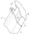
図2は本発明に係る物入れを備えるインナカバーの斜視図であり、インナカバー59は、フロントカウル(図1の符号58)の後方から前方に向け取り付けられるとともに、フロントカウル58に連続して設けられている部材である。インナカバー59は、運転者が座るフロントシート(図1の符号33)の前部に対向し、運転者が座った状態で手を伸ばしたときに、届く位置に配置されている。
インナカバー59には、物入れ60が備えられ、物入れ60の前面はリッド60aで覆われている。従って、運転者は手を伸ばして、物入れ60を容易に開閉操作することができる。物入れ60の構造については、次図以降で詳述する。
FIG. 2 is a perspective view of an inner cover having a container according to the present invention. The
The
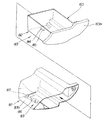
図3は本発明に係る物入れを全開位置にした状態を説明する斜視図であり、インナカバー59に取り付けられている物入れ60を取り出したものである。
物入れ60は、インナカバー(図2の符号59)に取り付けられている収納ケース81と、この収納ケース81に水平スライド可能に設けられている引き出し82とを備える。全開時には、図示せぬストッパにより、引き出し82が収納ケース81から落下しないようになっており、このストッパを解除することで、収納ケース81から引き出し82を容易に取り外すことができる。
すなわち、物入れ60には、小物を収納する引き出し82と、この引き出し82を図矢印s方向に水平スライド可能に収納する収納ケース81とが備えられている。
FIG. 3 is a perspective view for explaining a state in which the container according to the present invention is in the fully open position, in which the
The
In other words, the
図4は本発明に係る物入れの構成要素を説明する分解斜視図であり、前述のように、物入れ60には、引き出し82と収納ケース81とが備えられている。引き出し82と収納ケース81の一方及び他方には、引き出し82が乗員側へ引き出される際に中間位置で引き出し82を一旦停止させる中開停止機構83が設けられている。
FIG. 4 is an exploded perspective view for explaining the components of the container according to the present invention. As described above, the
中開停止機構83は、引き出し82に設けられピン状突起84を備えるアーム部材85と、ピン状突起84を案内するために、収納ケース81の底板81bに複数設けられた溝群86とからなる。
The intermediate
溝群86は、収納ケース81に設けられている。すなわち、溝群86を引き出し82側に設けていないため、引き出し82の収納容量が減ることはなく、引き出し82の収納容量を十分に確保することができる。
加えて、アーム部材85は、引き出し82側に設けられているので、引き出し82を外すことで、アーム部材85のメンテナンスを容易に行うことができる。
The
In addition, since the
なお、本実施例において、溝群86は、収納ケース81に設け、アーム部材85は、引き出し82に設けたものであるが、溝群86を引き出し82に設け、アーム部材85を収納ケース81に設けることは差し支えない。
In this embodiment, the
図5は本発明に係る引き出しを開方向に付勢する弾発機構を説明する断面図であり、収納ケース81の入口である開口部91の近傍を一部拡張させ形成した小ポケット92に弾発機構93が取り付けられている。
FIG. 5 is a cross-sectional view for explaining a resilient mechanism for urging the drawer in the opening direction according to the present invention. The resilient mechanism is formed in a
弾発機構93は、小ポケット92に配置されており、収納ケース81側に取り付ける軸部94と、この軸部94に回動自在に取り付けるドラム95と、このドラム95に巻掛けられる薄板状のスパイラルスプリング96と、このスパイラルスプリング96の先端部96aに取り付けられているフック部材97と、からなる。
弾発機構93は、ドラム95にスパイラルスプリング96が巻き掛けられており、このスパイラルスプリング96が延ばされているとき、フック部材97にはドラム95方向に巻き取る力Fが加わるように構成したものである。
The
フック部材97は、引き出し82の底板82bの最奥部に形成されているフック掛部98に引っ掛けられている。フック掛部98は、引き出し82が全開位置(K)にあるとき、弾発機構93に最も接近した位置となり、引き出し82が全閉位置(H)にあるとき、弾発機構93から最も離れた位置となるように配置されている。
弾発機構93のフック部材97を引き出し82のフック掛部98に引っ掛けることで、引き出し82を全開位置(K)となる方向に付勢することができる。
The
By hooking the
収納ケース81に、全閉位置(H)にある引き出し82を開放側に弾発付勢する弾発機構93を設けると、引き出し82は全開位置(K)に移動しようとするので、引き出し82を全閉位置(H)あるいは中開位置(TK)で保持する機構が必要となる。
引き出し82を全閉位置(H)又は中開位置(TK)に保持する機構として、物入れ60には、引き出し82を全閉位置(H)で保持するロック機構及び中開位置(TK)で保持する中開停止機構が設けられている。その詳細について、次図以降で説明する。
If the
As a mechanism for holding the
図6は本発明に係る先端にピン状突起を有するアーム部材を説明する断面図であり、引き出し82の底板82bの後端部99には凹部101が形成され、この凹部101に先端にピン状突起84を有するアーム部材85が設けられている。
FIG. 6 is a cross-sectional view illustrating an arm member having a pin-like protrusion at the tip according to the present invention. A
アーム部材85は、凹部101の水平面101sに直角に取り付けられる支持ピン102と、この支持ピン102に後端85bが挿通され、収納ケース81に支持ピン102を軸として図表裏方向に回動可能に取り付けられるアーム部材85とからなる。このアーム部材85は、その先端85aに下方に突設されているピン状突起84を備えている。このピン状突起84の先端部84aは、引き出し82の底板82bの底面82cよりも下方に延設され、溝群86との間で長さLのラップ代をもたせた。また、支持ピン102とアーム部材85は、底板82bの底面82cよりも上方で凹部101に納まるように配置されている。
すなわち、アーム部材85は、引き出し82に平面視で水平旋回可能に設けられ、アーム部材85の先端部85aにピン状突起84を備えている。
The
That is, the
図中、103はワッシャ、104は支持ピン102を固定する固定リングである。なお、ピン状突起84は、アーム部材85に溶接で固定されている。
In the figure, 103 is a washer, and 104 is a fixing ring for fixing the
図7は本発明に係る先端にピン状突起を有するアーム部材のロック機構を説明する図及びロック機構の作用図である。
引き出し(図5の符号82)は、弾発機構(図5の符号93)によって開放側に付勢されているので、引き出し82を全閉位置に保持するため、収納ケース(図5の符号81)には、ロック機構87が設けられている。
FIG. 7 is a view for explaining a locking mechanism of an arm member having a pin-like protrusion at the tip according to the present invention and an operation view of the locking mechanism.
Since the drawer (
ロック機構87は、収納ケース81側に取り付けられピン状突起84を受ける平面視略U字状の受け部105を有するホルダ部材106と、このホルダ部材106にばね107を介してスライド可能に設けられピン状突起84を保持又は開放するストッパ108と、このストッパ108に接続されストッパ108を矢印a方向に引くケーブル109と、を主要な構成要素とする。ケーブル109は、図示せぬアクチュエータに接続されている。
ばね107はストッパ108を図矢印b方向に付勢する部材である。
The
The
(a)において、ピン状突起84は、受け部105に収納されるとともに、ストッパ108はばね107により付勢されているので、通常、ストッパの先端部108aで受け部105の入口105aを塞ぐことができる。ピン状突起84は、受け部105に保持されているとき、引き出し82は全閉位置に保持される。
In (a), since the pin-shaped
(b)において、ケーブル109を引き、ばね107の付勢に抗してストッパ108を矢印a方向に移動させる。これにより、ストッパ108の先端部108aは受け部105の入口105aを塞ぐことなく、ピン状突起84は開放可能となっている。ピン状突起84は、矢印c方向に移動可能となるとともに、引き出し82を全閉位置から開放することができる。
In (b), the
(c)において、引き出し(図5の符号82)を閉じるときに、引き出し82が閉じる方向に移動し、引き出し82の底板に取り付けたピン状突起84がストッパ108の先端部108aに当たり、ばね107による付勢に抗してストッパ108を矢印d方向に移動させ、ピン状突起84が受け部105に収納され、その直後に、ストッパ108の先端部108aが受け部105の入口を塞ぐことで、ピン状突起84を保持する。ピン状突起84は、受け部105に保持され、引き出し82を全閉位置に保持することができる。
In (c), when the drawer (
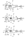
図8は本発明に係る溝群を含む中開停止機構の構成を説明する図及び中開停止機構の作用説明図(引き出しを全開位置から全閉位置にするとき)である。
引き出し(図5の符号82)が全閉位置にあるとき、ピン状突起84はロック機構87の受け部105に位置し、引き出し82が半開位置にあるとき、ピン状突起84は袋小路部111に位置し、引き出し82が全開位置にあるとき、ピン状突起84は第1ガイド溝112の開端部113に位置するものである。
中開停止機構83は、収納ケース81の底板81bに、引き出し82のスライド方向に延設された溝群86を備える。この溝群86は、引き出し82に設けるピン状突起84を案内するものである。
FIG. 8 is a view for explaining the configuration of the intermediate opening stop mechanism including the groove group according to the present invention and an operation explanatory view of the intermediate opening stop mechanism (when the drawer is moved from the fully open position to the fully closed position).
When the drawer (
The middle
収納ケース81に備える溝群86は、引き出し82が全開位置から全閉位置まで閉じる際に、ピン状突起84を案内する第1ガイド溝112と、引き出し82が全閉位置から中開位置にまで開く際に、アーム部材(図6の符号85)に備えるピン状突起84を案内するとともに、中開位置でピン状突起84が当接する袋小路部111を有する第2ガイド溝114と、この第2ガイド溝と第1ガイド溝112との間を連結し、ピン状突起84を案内する連絡溝115と、からなる。
The
連絡溝115は、袋小路部111に、引き出し82がスライドする方向に鋭角(0<α<90°)となるように接続され、引き出し82が全閉位置から中開位置まで移動する際には、ピン状突起84が袋小路部111への通過を可能とし、引き出し82が中開位置から全開位置に移動する際には、連絡溝115への通過を強いる逆止機構116を、袋小路部111の入口111aに備える。
The connecting
逆止機構116を詳細に説明すると、袋小路部111を平面視でV字状にするとともに第1ガイド溝112と第2ガイド溝114と連絡溝115とで囲われる部分を三角形部118にし、この三角形部118の袋小路部111に面する頂点119の近傍に軸部材121を立て、この軸部材121に、逆止腕122の後端122bを回動可能に挿通し、軸部材121を中心に、逆止腕122の先端122aをスイング可能に取り付け、通常時には、第2ガイド溝114を横切るように配置し、ピン状突起84が通過するときに、ピン状突起84に付勢されて第2ガイド溝114を開放するように逆止腕122と三角形部118に立設した止め部材117の間にスプリング123を介在させた。
The
溝群86は、引き出し(図5の符号82)の全開位置から全閉位置までピン状突起84を案内する第1ガイド溝112と、全閉位置を起点として第1ガイド溝112とは別個にほぼ直線的に延ばされ、引き出し82の全閉位置から中開位置までピン状突起84を案内する第2ガイド溝114と、この第2ガイド溝114の端部に設けられピン状突起84を中開位置で一旦停める袋小路部111と、この袋小路部111から全閉位置側へ傾斜して延ばされ第1ガイド溝112の途中に交叉する連絡溝115と、からなる。そして、第2ガイド溝114を全閉位置から中開位置へ向かって進むピン状突起84の通過は許容するが、ピン状突起84が全閉位置へ戻ることは妨げる逆止機構116を、袋小路部111の入口に付設した。
The
また、第1ガイド溝112の端部112aには、収納ケース81の端部81aまで延出して開放される開放端124を有し、この開放端124を末広がりに形成する。
第1ガイド溝112の端部112aは、収納ケース81の端部81aまで延出して開放される開放端124を有するので、ピン状突起84を有するアーム部材85を第1ガイド溝112に容易に嵌合させることができる。従って、引き出し82を収納ケース81に容易に組み付けることができる。
Further, the
Since the
図9は本発明に係る中開停止機構の構成及び作用説明図(引き出しを中開位置にしこの中開位置から全開位置にするとき)である。
引き出し(図5の符号82)を全閉位置から中開位置にするときには、ロック機構87のストッパ108を矢印m方向に移動させ、ピン状突起84を開放させると、引き出し82を全閉位置から中開位置へ引き出すことができる。前述のように、引き出し82が中開位置にあるとき、ピン状突起84は、袋小路部111に位置するものである。
FIG. 9 is a diagram for explaining the configuration and operation of the middle opening stop mechanism according to the present invention (when the drawer is in the middle opening position and the middle opening position is changed to the full opening position).
When the drawer (
このとき、袋小路部111の入口111aには、第2ガイド溝114を全閉位置から中開位置へ向かって進むピン状突起84の通過は許容するが、ピン状突起84が全閉位置へ戻ることは妨げる逆止機構116を付設したので、ピン状突起84が袋小路部111に到達すると、ピン状突起84が第2ガイド溝114に戻ることはない。
ピン状突起84が第2ガイド溝114に戻ることはないので、引き出し(図5の符号82)を中開位置に停めることができる。
At this time, passage of the pin-
Since the pin-shaped
引き出し(図5の符号82)を中開位置から全開位置に開けるときには、袋小路部111で停められているピン状突起84は、引き出し82を少し戻すことで連絡溝115を矢印n方向に進んで連絡溝115と第1ガイド溝112の接続点である移行点126に達し、その後、第1ガイド溝112に移り、最後に引き出し82を引いたとき、ピン状突起84は第1ガイド溝112を進み、引き出し82を全開位置まで引き出すことができる。つまり、運転者は引き出し82を押し引きするだけで、半開位置から全開位置にすることができる。
When the drawer (
従って、運転者は、中開位置にある引き出し82を全開位置まで開く操作を極めて容易に行うことができる。押し引きする操作のみで引き出し82を中開位置から全開位置に開くことができるので、運転者の体格によって引き出しの開く操作が煩雑となることもない。
Therefore, the driver can perform the operation of opening the
図8に戻って、引き出し(図5の符号82)を閉じるときには、第1ガイド溝112の開放部113から、ピン状突起84が矢印n方向に移動し、ロック機構87の受け部105に達すると、ストッパ108によりピン状突起84が受け部105に保持され、引き出し82は全閉位置に保持される。
つまり、ピン状突起84が第1ガイド溝112を進むことで全開位置から全閉位置に到る。
Returning to FIG. 8, when closing the drawer (
That is, the pin-shaped
図10は引き出しが中開位置又は全開位置にあることを説明する斜視図である。
(a)は引き出し82が中開位置に位置するものであり、ピン状突起(図9の符号84)が、第2ガイド溝114に設けた袋小路部111に当たっているときの状態を示す。
(b)は引き出し82が全開位置にあることを示し、ピン状突起84が、第1ガイド溝112の開端部113に位置しているときの状態を示す。
FIG. 10 is a perspective view for explaining that the drawer is in the middle open position or the fully open position.
(A) shows the state when the
(B) shows that the
引き出し82を中開位置(中開停止位置)から全開位置にするには、運転者は引き出し82を押し引きするだけで済む。従って、中開位置にある引き出し82を全開位置まで開く操作を極めて容易に行うことができる。
In order to move the
運転者はリッド60aをつかんで、押し引きするだけで全開位置とすることができる。従って、運転者は、中開位置にある引き出し82を全開位置まで開く操作を極めて容易に行うことが可能となる。また、中開停止機構83は、溝群86とピン状突起84を有するアーム部材85とからなる簡便な構成のため、収納ケース81への引き出し82の組付を容易に行うことができる。また、簡便な構成ゆえにアーム部材85のメンテナンスも容易である。
The driver can reach the fully open position by simply grasping and pushing and pulling the
図11は図8の別実施例図であり、主な相違点は、逆止機構116を省略した点にある。
袋小路部111を平面視でV字状にするとともに第1ガイド溝112と第2ガイド溝114と連絡溝115とで囲われる部分を三角形部118にし、この三角形部118の袋小路部111に面する頂点119よりも、袋小路部111のV字底127が第1ガイド溝112寄りに位置するように袋小路部111を定めた。
FIG. 11 is a diagram of another embodiment of FIG. 8, and the main difference is that the
The
図12は図9の別実施例図であり、収納ケース(図5の符号81)に、全閉位置にある引き出し(図5の符号82)を開放側に、全開位置に至るまで弾発付勢する弾発機構(図5の符号93)と、中開停止機構83により、中開位置で停止した引き出し82を、閉じる方向に操作せしめることで、中開停止機構83を解除させる連絡溝115を含む停止解除機構130と、が備えられ、引き出し82は、閉じる方向に操作され、中開停止機構83が解除された後に全開位置で停止するようにした。
FIG. 12 is a diagram showing another embodiment of FIG. 9, in which a drawer (
引き出し82には、開放側に弾発付勢する弾発機構(図5の符号93)を設けたので、中開位置で、ピン状突起84は袋小路部111に当たるとともに袋小路部111に付勢されている。
Since the
袋小路部111を平面視でV字状にするとともに第1ガイド溝112と第2ガイド溝114と連絡溝115とで囲われる部分を三角形部118にし、この三角形部118の袋小路部111に面する頂点119よりも、袋小路部111のV字底127が第1ガイド溝112寄りに位置するように袋小路部111を定めたので、袋小路部111に入ったピン状突起84は、引き出し82を少し戻したときに、連絡溝115に移行し、第1ガイド溝112と接続する移行点126に移る。
The
引き出し82には、開放側に弾発付勢する弾発機構93を設け、袋小路部111のV字底127が第1ガイド溝112寄りに位置するように袋小路部111を定めたので、引き出し82を中開位置から全開位置にするときには、ピン状突起84を連絡溝115に移行させ、最後に、第1ガイド溝112に移行させることができる。従って、引き出し82を全開位置に開放させることができる。
The
袋小路部111のV字底127が第1ガイド溝112寄りに位置するように袋小路部111を定めたので、袋小路部111の入口111aに設けていた逆止機構116は不要となる。逆止機構116が不要となるので、中開停止機構83の構造を簡便にすることができる。
Since the
尚、本発明は、実施の形態では自動二輪車に適用したが、四輪車にも適用可能であり、一般の車両に適用することは差し支えない。
請求項1では、袋小路部の入口に付設する逆止機構を省略することは差し支えない。
また、収納ケースに設け引き出しを開放側に弾発付勢する弾発機構を省略することは差し支えない。
Although the present invention is applied to a motorcycle in the embodiment, it can also be applied to a four-wheeled vehicle and can be applied to a general vehicle.
In claim 1, it is possible to omit the check mechanism attached to the entrance of the bag path.
In addition, it is possible to omit the bullet mechanism that is provided in the storage case and urges the drawer toward the open side.
さらに、第2ガイド溝の端部又は第1ガイド溝の端部に有する開放端を末広がりに形成することなく、溝幅のまま開放端とすることは差し支えない。 Further, the open end of the end of the second guide groove or the end of the first guide groove may be formed as an open end without changing the width of the groove without forming the end wide.
本発明は、自動二輪車の収納ボックスに好適である。 The present invention is suitable for a storage box for a motorcycle.
60…物入れ、81…収納ケース、81a…収納ケースの端部、82…引き出し、83…中開停止機構、84…ピン状突起、84a…ピン状突起の先端、85…アーム部材、86…溝群、111…袋小路部、111a…袋小路部の入口、112…第1ガイド溝、114…第2ガイド溝、114a…第2ガイド溝の端部、115…連絡溝、116…逆止機構、118…三角形部、119…頂点、124…開放端、127…V字底、130…停止解除機構。 60 ... Container, 81 ... Storage case, 81a ... End of storage case, 82 ... Drawer, 83 ... Middle open stop mechanism, 84 ... Pin-like projection, 84a ... Tip of pin-like projection, 85 ... Arm member, 86 ... Groove Group: 111 ... Sack alley section, 111a ... Entrance of the bag alley section, 112 ... First guide groove, 114 ... Second guide groove, 114a ... End of second guide groove, 115 ... Communication groove, 116 ... Check mechanism, 118 ... Triangle part, 119 ... Vertex, 124 ... Open end, 127 ... V-shaped bottom, 130 ... Stop release mechanism.
Claims (7)
前記収納ケースに、全閉位置にある前記引き出しを開放側に、全開位置に至るまで弾発付勢する弾発機構と、
前記中開停止機構により、中開位置で停止した前記引き出しを、閉じる方向に操作せしめることで、前記中開停止機構を解除させる停止解除機構を備え、
前記引き出しは、閉じる方向に操作され、前記中開停止機構を解除された後に全開位置で停止することを特徴とする車両に装備される物入れ。 The vehicle is equipped with a drawer for storing small articles, a storage case for storing the drawer in a horizontally slidable manner, and an intermediate opening stop mechanism for temporarily stopping the drawer at an intermediate position when the drawer is pulled out to the occupant side. In the container
In the storage case, a bullet mechanism that urges and urges the drawer in the fully closed position until it reaches the fully open position;
A stop release mechanism for releasing the intermediate open stop mechanism by operating the drawer stopped at the intermediate open position in the closing direction by the intermediate open stop mechanism,
The drawer is operated in a closing direction and stops at a fully open position after the intermediate opening stop mechanism is released, and the container is provided in the vehicle.
この溝群は、前記引き出しの全開位置から全閉位置まで前記ピン状突起を案内する第1ガイド溝と、全閉位置を起点として前記第1ガイド溝とは別個にほぼ直線的に延ばされ、引き出しの全閉位置から中開位置まで前記ピン状突起を案内する第2ガイド溝と、この第2ガイド溝の端部に設けられ前記ピン状突起を中開位置で一旦停める袋小路部と、この袋小路部から全閉位置側へ傾斜して延ばされ前記第1ガイド溝の途中に交叉する連絡溝と、からなり、
前記引き出しを開けると、前記ピン状突起が直線状の前記第2ガイド溝を進むため前記袋小路部で一旦停められ、次に前記引き出しを少し戻すことで前記ピン状突起が前記連絡溝を進んで前記第1ガイド溝に移り、次に前記引き出しが引き出されることで前記ピン状突起は前記第1ガイド溝を進み全開位置に到り、前記引き出しを閉じるときには前記ピン状突起が前記第1ガイド溝を進むことで全開位置から全閉位置に到るように構成したことを特徴とする請求項1記載の車両に装備される物入れ。 The middle opening stop mechanism is provided in the drawer case or the drawer case so as to be horizontally pivotable, and has an arm member provided with a pin-like projection at the tip, and the storage case or the drawer to guide the pin-like projection, It consists of a group of grooves extending in the sliding direction of the drawer,
This groove group is extended substantially linearly separately from the first guide groove for guiding the pin-shaped protrusion from the fully open position to the fully closed position of the drawer and the first guide groove starting from the fully closed position. A second guide groove that guides the pin-shaped protrusion from the fully closed position of the drawer to the middle-open position, and a bag path portion that is provided at an end of the second guide groove and temporarily stops the pin-shaped protrusion at the middle-open position; A communication groove extending from the bag path portion to the fully closed position side and extending in the middle of the first guide groove,
When the drawer is opened, the pin-like projection advances through the second guide groove in a straight line, so that the pin-like projection advances temporarily through the communication groove by returning the drawer slightly. The pin-shaped projection advances to the first guide groove by moving to the first guide groove and then the drawer is pulled out, reaches the fully open position, and when the drawer is closed, the pin-shaped projection is moved to the first guide groove. 2. The container mounted on the vehicle according to claim 1, wherein the container is configured to reach from a fully open position to a fully closed position by proceeding through.
前記ピン状突起が一旦袋小路部にて止められた後に、前記引き出しを少し戻すと、前記ピン状突起は前記連絡溝を通って前記第1ガイド溝に進入して前記引き出しが全開となることを特徴とする請求項2〜6のいずれか1項記載の物入れ。 After the pin-shaped protrusion is once stopped at the bag path, when the drawer is returned a little, the pin-shaped protrusion enters the first guide groove through the communication groove, and the drawer is fully opened. The container of any one of claims 2 to 6, characterized in that
Priority Applications (6)
| Application Number | Priority Date | Filing Date | Title |
|---|---|---|---|
| JP2006351738A JP4801581B2 (en) | 2006-12-27 | 2006-12-27 | Containers equipped in the vehicle |
| US11/978,727 US7854486B2 (en) | 2006-12-27 | 2007-10-30 | Container equipped on vehicle |
| DE602007003431T DE602007003431D1 (en) | 2006-12-27 | 2007-10-31 | Container mounted on a vehicle |
| EP07021326A EP1939081B1 (en) | 2006-12-27 | 2007-10-31 | Container equipped on vehicle |
| ES07021326T ES2335703T3 (en) | 2006-12-27 | 2007-10-31 | CONTAINER MOUNTED ON A VEHICLE. |
| CN2007101597147A CN101209727B (en) | 2006-12-27 | 2007-12-20 | Container equipped on vehicle |
Applications Claiming Priority (1)
| Application Number | Priority Date | Filing Date | Title |
|---|---|---|---|
| JP2006351738A JP4801581B2 (en) | 2006-12-27 | 2006-12-27 | Containers equipped in the vehicle |
Publications (3)
| Publication Number | Publication Date |
|---|---|
| JP2008162321A JP2008162321A (en) | 2008-07-17 |
| JP2008162321A5 JP2008162321A5 (en) | 2010-01-14 |
| JP4801581B2 true JP4801581B2 (en) | 2011-10-26 |
Family
ID=38979653
Family Applications (1)
| Application Number | Title | Priority Date | Filing Date |
|---|---|---|---|
| JP2006351738A Expired - Fee Related JP4801581B2 (en) | 2006-12-27 | 2006-12-27 | Containers equipped in the vehicle |
Country Status (6)
| Country | Link |
|---|---|
| US (1) | US7854486B2 (en) |
| EP (1) | EP1939081B1 (en) |
| JP (1) | JP4801581B2 (en) |
| CN (1) | CN101209727B (en) |
| DE (1) | DE602007003431D1 (en) |
| ES (1) | ES2335703T3 (en) |
Families Citing this family (5)
| Publication number | Priority date | Publication date | Assignee | Title |
|---|---|---|---|---|
| CN201182372Y (en) * | 2008-03-13 | 2009-01-21 | 佛山市顺德区泰明金属制品厂有限公司 | Drawer sliding rail switching-off devcie |
| JP2011201515A (en) * | 2010-03-26 | 2011-10-13 | Honda Motor Co Ltd | Saddle bag and motorcycle with the same |
| TWI507114B (en) * | 2013-09-30 | 2015-11-01 | Hon Hai Prec Ind Co Ltd | Removable loading device |
| US10023255B1 (en) * | 2015-10-26 | 2018-07-17 | Truman R Davis | Transportation storage system and method of use |
| CN114847683A (en) * | 2022-04-18 | 2022-08-05 | 拉扎斯网络科技(上海)有限公司 | Storage device |
Family Cites Families (15)
| Publication number | Priority date | Publication date | Assignee | Title |
|---|---|---|---|---|
| US2695831A (en) * | 1951-12-04 | 1954-11-30 | Sigal Solomon | Table with drawer and guide |
| US3539239A (en) * | 1968-10-23 | 1970-11-10 | Rubbermaid Inc | Cabinet with retractable door |
| DE3300926C2 (en) * | 1983-01-13 | 1986-11-13 | Audi AG, 8070 Ingolstadt | Storage containers, in particular for motor vehicles |
| US4494806A (en) * | 1983-05-13 | 1985-01-22 | Leslie Metal Arts Company | Spring loaded drawer assembly with mechanical damping |
| US4712845A (en) * | 1986-01-27 | 1987-12-15 | Ni Industries, Inc. | Self-opening receptacle assembly with adjustable rollers |
| JPH01159281A (en) | 1987-12-16 | 1989-06-22 | Tokyo Electric Co Ltd | Printing cap control apparatus |
| JP2611488B2 (en) * | 1990-04-25 | 1997-05-21 | 日産自動車株式会社 | Electric retract switch |
| JP2539974Y2 (en) * | 1990-06-18 | 1997-07-02 | 株式会社ニフコ | Article storage device |
| DE4038324A1 (en) * | 1990-11-30 | 1992-06-04 | Happich Gmbh Gebr | CONTAINER LIKE ASCHER, STORAGE COMPARTMENT OR THE LIKE ESPECIALLY FOR VEHICLES |
| US5393137A (en) * | 1993-06-11 | 1995-02-28 | Illinois Tool Works Inc. | Damper assembly |
| DE19636528A1 (en) * | 1996-09-09 | 1998-03-19 | Fischer Artur Werke Gmbh | Vehicle ashtray |
| JPH1159281A (en) | 1997-08-12 | 1999-03-02 | Kojima Press Co Ltd | Multistage opening and closing control mechanism and drawer for vehicle using it |
| JP3871931B2 (en) * | 2001-12-27 | 2007-01-24 | 本田技研工業株式会社 | Article storage structure for small vehicles |
| JP4020755B2 (en) * | 2002-10-31 | 2007-12-12 | 株式会社ニフコ | Cup holder device for car accessories |
| JP4372565B2 (en) * | 2004-01-20 | 2009-11-25 | 本田技研工業株式会社 | Vehicle storage structure |
-
2006
- 2006-12-27 JP JP2006351738A patent/JP4801581B2/en not_active Expired - Fee Related
-
2007
- 2007-10-30 US US11/978,727 patent/US7854486B2/en not_active Expired - Fee Related
- 2007-10-31 ES ES07021326T patent/ES2335703T3/en active Active
- 2007-10-31 DE DE602007003431T patent/DE602007003431D1/en active Active
- 2007-10-31 EP EP07021326A patent/EP1939081B1/en not_active Expired - Fee Related
- 2007-12-20 CN CN2007101597147A patent/CN101209727B/en active Active
Also Published As
| Publication number | Publication date |
|---|---|
| ES2335703T3 (en) | 2010-03-31 |
| EP1939081A1 (en) | 2008-07-02 |
| DE602007003431D1 (en) | 2010-01-07 |
| US20080157554A1 (en) | 2008-07-03 |
| EP1939081B1 (en) | 2009-11-25 |
| CN101209727A (en) | 2008-07-02 |
| CN101209727B (en) | 2010-12-01 |
| US7854486B2 (en) | 2010-12-21 |
| JP2008162321A (en) | 2008-07-17 |
Similar Documents
| Publication | Publication Date | Title |
|---|---|---|
| JP4801581B2 (en) | Containers equipped in the vehicle | |
| US7841639B2 (en) | Utility vehicle equipped with extendable cargo bed | |
| US6709042B2 (en) | Motorcycle with window screen structure | |
| JP4451140B2 (en) | Arrangement structure for unlocking operation member in vehicle | |
| JP2621193B2 (en) | Motorcycle | |
| JP2005319901A (en) | Divided lid mechanism, and center console box | |
| JP2008260504A (en) | Motorcycle | |
| FR2955294A1 (en) | Cabriolet, has control unit provided for driving device and position detection device for flap, and permitting adjustment of wind deflector element when position detection device detects pre-determined position of flap | |
| JPH01223091A (en) | Scooter type vehicle | |
| JP5095448B2 (en) | Motorcycle screen support structure | |
| JP4648132B2 (en) | Vaporizer arrangement structure in small vehicles | |
| JP2003154982A (en) | Pillion step structure for scooter type motorcycle | |
| JP4372565B2 (en) | Vehicle storage structure | |
| JP4581944B2 (en) | Motorcycle side bag support device | |
| JP4372564B2 (en) | Arrangement structure for unlocking operator in vehicle | |
| JP6816095B2 (en) | Saddle-type vehicle storage structure | |
| JP2007283988A (en) | Trunk structure of motorcycle | |
| JPS6234870A (en) | Glove compartment for scooter type car | |
| JPH07112686A (en) | Fuel lid for vehicle | |
| JP6291779B2 (en) | Seat hinge structure for saddle riding type vehicle and saddle riding type vehicle | |
| JP2012011923A (en) | Stand for bicycle | |
| JP4400962B2 (en) | Motorcycle rear cowl | |
| JP6709327B2 (en) | Saddle type vehicle | |
| JP5010942B2 (en) | Scooter type vehicle | |
| JP3626268B2 (en) | Body structure for reducing the air resistance of motorcycles |
Legal Events
| Date | Code | Title | Description |
|---|---|---|---|
| A521 | Written amendment |
Free format text: JAPANESE INTERMEDIATE CODE: A523 Effective date: 20091120 |
|
| A621 | Written request for application examination |
Free format text: JAPANESE INTERMEDIATE CODE: A621 Effective date: 20091120 |
|
| TRDD | Decision of grant or rejection written | ||
| A977 | Report on retrieval |
Free format text: JAPANESE INTERMEDIATE CODE: A971007 Effective date: 20110729 |
|
| A01 | Written decision to grant a patent or to grant a registration (utility model) |
Free format text: JAPANESE INTERMEDIATE CODE: A01 Effective date: 20110802 |
|
| A01 | Written decision to grant a patent or to grant a registration (utility model) |
Free format text: JAPANESE INTERMEDIATE CODE: A01 |
|
| A61 | First payment of annual fees (during grant procedure) |
Free format text: JAPANESE INTERMEDIATE CODE: A61 Effective date: 20110805 |
|
| FPAY | Renewal fee payment (event date is renewal date of database) |
Free format text: PAYMENT UNTIL: 20140812 Year of fee payment: 3 |
|
| R150 | Certificate of patent or registration of utility model |
Ref document number: 4801581 Country of ref document: JP Free format text: JAPANESE INTERMEDIATE CODE: R150 Free format text: JAPANESE INTERMEDIATE CODE: R150 |
|
| LAPS | Cancellation because of no payment of annual fees |